FUEL REFORMING TECHNOLOGIES (BRIEFING SLIDES)
|
|
|
- Dylan Malone
- 5 years ago
- Views:
Transcription
1 AFRL-RX-TY-TP FUEL REFORMING TECHNOLOGIES (BRIEFING SLIDES) Robert Diltz Air Force Research Laboratory SEPTEMBER 2009 DISTRIBUTION STATEMENT A: Approved for public release; distribution unlimited. AIRBASE TECHNOLOGIES DIVISION MATERIALS AND MANUFACTURING DIRECTORATE AIR FORCE RESEARCH LABORATORY AIR FORCE MATERIEL COMMAND 139 BARNES DRIVE, SUITE 2 TYNDALL AIR FORCE BASE, FL
2 REPORT DOCUMENTATION PAGE Form Approved OMB No The public reporting burden for this collection of information is estimated to average 1 hour per response, including the time for reviewing instructions, searching existing data sources, gathering and maintaining the data needed, and completing and reviewing the collection of information. Send comments regarding this burden estimate or any other aspect of this collection of information, including suggestions for reducing the burden, to Department of Defense, Washington Headquarters Services, Directorate for Information Operations and Reports ( ), 1215 Jefferson Davis Highway, Suite 1204, Arlington, VA Respondents should be aware that notwithstanding any other provision of law, no person shall be subject to any penalty for failing to comply with a collection of information if it does not display a currently valid OMB control number. PLEASE DO NOT RETURN YOUR FORM TO THE ABOVE ADDRESS. 1. REPORT DATE (DD-MM-YYYY) 2. REPORT TYPE 3. DATES COVERED (From - To) 03-SEP-2009 Conference Presentation 01-JAN AUG TITLE AND SUBTITLE 5a. CONTRACT NUMBER Fuel Reforming Technologies (BRIEFING SLIDES) 5b. GRANT NUMBER FA D AUTHOR(S) Diltz, Robert 5c. PROGRAM ELEMENT NUMBER 5d. PROJECT NUMBER 5e. TASK NUMBER 5f. WORK UNIT NUMBER 7. PERFORMING ORGANIZATION NAME(S) AND ADDRESS(ES) 8. PERFORMING ORGANIZATION REPORT NUMBER Air Force Research Laboratory Airbase Technologies Division 139 Barnes Drive, Suite 2 Tyndall Air Force Base, FL SPONSORING/MONITORING AGENCY NAME(S) AND ADDRESS(ES) 10. SPONSOR/MONITOR'S ACRONYM(S) Air Force Research Laboratory Materials and Manufacturing Directorate Airbase Technologies Division 139 Barnes Drive, Suite 2 Tyndall Air Force Base, FL DISTRIBUTION/AVAILABILITY STATEMENT Distribution Statement A: Approved for public release; distribution unlimited. 13. SUPPLEMENTARY NOTES 14. ABSTRACT 62012F 4915 C1 4915C19C AFRL/RXQD 11. SPONSOR/MONITOR'S REPORT NUMBER(S) AFRL-RX-TY-TP Ref AFRL/RXQ Public Affairs Case # Document contains color images. For presentation at congregation at German international collaboration meeting, 15 September, Karlsruhe, Germany The AFRL/RXQD Energy program demonstrates current technologies in solar power generation and the integration of these technologies onto deployed base structures. This presentation is to describe those efforts along with the capabilities and competencies that have come as a result of this program. 15. SUBJECT TERMS JP-8, fuel reforming, solid oxide fuel cell, catalysis 16. SECURITY CLASSIFICATION OF: a. REPORT b. ABSTRACT c. THIS PAGE 17. LIMITATION OF ABSTRACT U U U UU 18. NUMBER OF PAGES 15 19a. NAME OF RESPONSIBLE PERSON Robert Diltz 19b. TELEPHONE NUMBER (Include area code) Reset Standard Form 298 (Rev. 8/98) Prescribed by ANSI Std. Z39.18
3 Fuel Reforming Technologies 1


4 Deployed Energy & Utility Systems Overview Mission Conduct Exploratory, Advanced, and Applied Research To Develop Next Generation Deployed Energy and Utility Systems To Meet New and Evolving Warfighter Needs Benefit To The Warfighter Reduce Deployed Footprint While Enhancing Operational Efficiencies And Maintenance Requirements 50% Reduction In Power Deployment Airlift 82% Reduction In Fuel Consumption Reduce / Eliminate External Fuel Requirements, Saves Lives Of Soldiers, Marines, Sailors, and Airmen 2


5 Conversion Tech Development m Liquid wt.% JP 8 Q Feed td 1 60 Q LHSV h V Re Feed actor Combustion Catalyst JP8 Carbon Distribution ib ti nc 9 C 10 nc 11 nc nc 12 nc 14 nc 13 Cracking Catalyst nc 8 nc 15 nc 16 nc 17 Sulfur Distribution The Objectives: Develop The Underlying Concepts in Advanced Heat and Mass Transfer, Catalysis and Surface Chemistry, and Energy Conversion For an Efficient and Compact Energy System The Technical Approach: Applying Transport Phenomena Theories, Formulation, and Modeling; Computational and Experimental Fluid Dynamics; Catalyst Kinetics Modeling, Catalyst Chemistry and Surface Analysis, Reactions Thermodynamics Modeling, Novel Catalyst Materials Formulation, and Catalyst Coating On Substrate; Catalytic Reactor system Testing and Analysis; Synthesis of Panchromatic Sensitizers; And Experimentation and Analysis To Accomplish These Goals: In-House and Contracted Research to Universities and Industry, Leveraging and Collaborating with National Laboratories and DoD Services 3


6 Multi-fuel Reformer Objective Develop Reformer System Capable Of Converting Liquid Fuels Into Hydrogen For More Efficient Use In Fuel Cell Stacks Technology Challenges Novel catalyst materials formulation Catalytic reactor system testing and analysis Catalyst Coating On Metal Substrate Reactions Thermodynamics Modeling Process water recovery Benefits to the Warfighter To Reduce Deployed Energy Systems Footprint While Enhancing Operational Efficiencies And Maintenance Requirements To Achieve 60% Reduction In Power Deployment Airlift (from 4 Sorties down to less than 2 Sorties) To Save 3400 Gallons Of Fuel/Day/1100men Deployment To Reduce Noise/Thermal Signature And Environmental Emissions 4
7 Advanced Heat and Mass Transfer 5


 Increase In MTBF From 500 Hrs To")
8 Advanced Heat and Mass & Transfer Technologies Objective Identify And Develop New Technologies To Enhance Heat And Mass Transfer In Deployed Energy Systems Technology & Core Competency Microchannel and Matrix Technologies Transport Phenomena Theory, Formulation, And Modeling Computational And Experimental Fluid Dynamics Mechanical Design And Instrumentation Laboratory Experimentation And Analysis Collaboration With Academia And Industry Benefits to the War Fighter Reduce Deployed Footprint While Enhancing Operational Efficiencies And Maintenance Requirements 50% Reduction In Power Deployment Airlift (From 4 Sorties Down To Less Than 2 Sorties Of C-130 Per 1100 Men) Increase In MTBF From 500 Hrs To 2200 Hrs. Savings Of 1800 Gallons Of Fuel/Day/1100 Man 6
9 Catalysis Technologies 7


10 Catalysis Technologies JP8 Carbon Distribution nc 8 nc 9 nc 10 nc 11 nc 13 nc nc 15 nc 1 nc 16 C 17 n nc Sulfur Distributi on Objective Develop New Catalysis Technologies For Process Intensification To Enhance Performance of Deployed Energy Systems Technology & Core Competency Catalyst Kinetics Modeling and Testing Catalyst Chemistry and Screening Surface Analysis and Chemistry Reactions Thermodynamics Modeling Novel Catalyst Materials Formulation Catalyst Coating On Metal Substrate Catalytic Reactor system Testing and Analysis Benefits to the War Fighter Cracking Catalyst Combustion Catalyst 50% Reduction in Power Deployment Airlift (from 4 Sorties down to less than 2 Sorties of C-131 per 1100 men) Increase in MTBF from 500 hrs to 2200 hrs. Savings of 1800 gallons of fuel/day/1100man deployment (5,280 Gal. vs. 3,480 Gal.) Reduced Noise Signature (70 db vs. 120 db) 8


11 Process Intensification Impact Reduced Steam Reformer Size By 10 Folds 9
12 Preliminary Test Results Comparison Hydrocarbon Fuel Evaporator Fractionation Steam Reforming AFRL/RXQD Multi-Fuel Reformer Steam Condensation Gas / Liquid Separator Sulfur Removal Fuel Cell Fuel Heavy Fractions Steam Generator To Burners Water Tank Water Recovery The preliminary test results confirmed the benefits of using FT-Petroleum 50/50 mix over Petroleum JP-8: Due to the reduction in aromatics and sulfur contents, the mix test runs were conducted without the use of fractionation. This has the potential to eliminate the fractionation component and reduce the size of the sulfur removal component by 50%--less maintenance. The mixed blend behaved similarly to Petroleum JP-8, however, it burned cleaner and processed fuel at much lower temperatures without producing non-condensable aerosol. Achieved complete conversion with less CO 2 and no higher hydrocarbons than methane was detected. Methane and CO along with H 2 are fuels for the Solid Oxide Fuel Cell (SOFC). 10
13 Preliminary Test Results Comparison Test Steam Runs H 2 CO CH 4 CO 2 C 2 H 4 C 2 H 6 C 3 H 6 Reformer Exit Temp Petroleum JP-8 [mol%] [mol%] [mol%] [mol%] [mol%] [mol%] [mol%] [C] % 12% 0% 12.8% 0% 0% 0% % 11.9% 3.8% 11.8% 0% 0% 0% /50 Petroleum JP-8 and FT JP-8 Mix % 12.4% 6.3% 6.3% 0% 0% 0% 640 Reported Data are the Average of Multiple Test Runs Each The preliminary test results confirmed the benefits of using FT-Petroleum 50/50 mix over Petroleum JP-8: Due to the reduction in aromatics and sulfur contents, the mix test runs were conducted without the use of fractionation. This has the potential to eliminate the fractionation component and reduce the size of the sulfur removal component by 50%--less maintenance. The mixed blend behaved similarly to Petroleum JP-8, however, it burned cleaner and processed fuel at much lower temperatures without producing non-condensable aerosol. Achieved complete conversion with less CO 2 and no higher hydrocarbons than methane was detected. Methane and CO along with H 2 are fuels for the Solid Oxide Fuel Cell (SOFC). 11


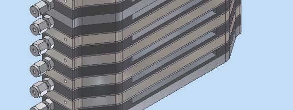
14 10kWe Lab Demo Unit 10kWe Steam Reformer Design 12
15 13