CCR Certification: Amended Inflow Design Flood Control System Plan for the. East Ash Pond. at the. F.B. Culley Generating Station.
|
|
|
- Sydney Greer
- 5 years ago
- Views:
Transcription
 One Vectren Square Evansville, IN 4772 Submitted by AECOM 94 Amberglen")

1 Submitted to Southern Indiana Gas & Electric Company dba Vectren Power Supply, Inc. (SIGECO) One Vectren Square Evansville, IN 4772 Submitted by AECOM 94 Amberglen Boulevard Austin, Texas February 1, 217 CCR Certification: Amended Inflow Design Flood Control System Plan for the East Ash Pond at the F.B. Culley Generating Station Revision 1
2 AECOM CCR Certification: Amended Inflow Design Flood Control System Plan for the East Ash Pond at the F.B. Culley Generating Station i Table of Contents Table of Contents Executive Summary Introduction Purpose of This Report Brief Description of Impoundment Inflow from Plant Operations and Stormwater Runoff Outlet Structures Hydrologic Analysis Design Storm Rainfall Data Runoff Computations Hydraulic Analyses Process Flows Storage Capacity Discharge Analysis Results Inflow Analysis Outflow Analysis Inflow Design Flood Discharge Conclusions Certification Limitations February 1, 217
3 AECOM CCR Certification: Amended Inflow Design Flood Control System Plan for the East Ash Pond at the F.B. Culley Generating Station ii Table of Contents Tables Table ES-1 Certification Summary Table 1-1 CCR Rule Cross Reference Table Table 4-1 Summary of Hydrologic and Hydraulic Analysis 1,-Year, 24-Hour Storm Table 4-2 Summary of Outlet Devices 1,-Year, 24-Hour Storm Appendices Appendix A Figures Figure 1 Location Map Figure 2 Site Map Figure 3 Drainage Area Map Appendix B Hydrologic and Hydraulic Calculations February 1, 217
4 AECOM CCR Certification: Amended Inflow Design Flood Control System Plan for the East Ash Pond at the F.B. Culley Generating Station ES-1 Executive Summary Executive Summary This Coal Combustion Residuals (CCR) Amended Inflow Design Flood Control System Plan (Inflow Flood Control Plan) for the East Ash Pond at the Southern Indiana Gas & Electric Company, dba Vectren Power Supply, Inc. F.B. Culley Generating Station has been prepared in accordance with the requirements specified in the USEPA CCR Rule under 4 Code of Federal Regulations CFR (e). These regulations require that the specified documentation, assessments and plans for an existing CCR surface impoundment be amended per (c)(2) when there is a change in conditions that would substantially affect the written plan in effect. CCR was recently removed from the East Ash Pond and the normal operating level was lowered to 396 which changed the storage capacity of the pond. In addition, a power generating unit at the plant returned to operation, increasing the process inflow into the pond; therefore the Initial Inflow Flood Control Plan has been amended. This Inflow Flood Control Plan meets the regulatory requirements as summarized in Table ES-1. Table ES-1 Certification Summary Report Section CCR Rule Reference Requirement Summary Requirement Met? Comments Initial Inflow Design Flood Control System Plan (a)(1) Adequately manage flow into the CCR unit during and following the peak discharge of the inflow design flood Yes CCR unit has the storage capacity to handle the inflow design flood (a)(2) Adequately manage flow from the CCR unit to collect and control the peak discharge resulting from the inflow design flood (a)(3) Required Inflow design flood for Significant Hazard Potential Impoundment Yes Yes The pond has adequate capacity to contain 1,- year 24-hour storm with or without operational outlet pumps. Inflow design flood utilized was the 1,-year event (b) Discharge handled in accordance with Yes CCR unit discharges in accordance with the existing NPDES permit The East Ash Pond is considered to be a significant hazard potential CCR surface impoundment, therefore per (a)(3), the inflow design flood is the 1,-year flood. In accordance with the requirements of February 1, 217
5 AECOM CCR Certification: Amended Inflow Design Flood Control System Plan for the East Ash Pond at the F.B. Culley Generating Station ES-2 Executive Summary (a)(3), an Inflow Flood Control Plan was developed for the East Ash Pond. This was accomplished by evaluating the effects of a 24-hour duration design storm for the 1,-year Inflow Design Flood (IDF) to evaluate the East Ash Pond s ability to collect and control the 1,-year IDF of 1.2-inches, under existing operational and maintenance procedures. In accordance with the requirements of (c)(2), changes in the conditions that would substantially affect the written plan in effect requires the amendment of the Inflow Flood Control Plan. Since the October 217 certification of the Initial Inflow Design Flood Control System Plan, CCR material has been removed, the interior of the East Ash Pond has been regraded pond, and process inflow rate to the pond has changed. The East Ash Pond consists of two interconnected ponds. The only outlet from the pond is a pump station. This outlet does not allow for free flow discharge if the pump station was to malfunction or lose power. To simulate the worst case scenario, the analysis was completed with no pumps running in the East Ash Pond as if there was a malfunction or power outage at the pump station. Therefore, the East Ash Pond would be required to collect and store the 1,-year IDF. The results of the modeling for the East Ash Pond indicate that the CCR unit has sufficient storage capacity and outlet structures to adequately manage inflows and collect and control outflows during peak discharge conditions created by the 1,-year IDF. February 1, 217
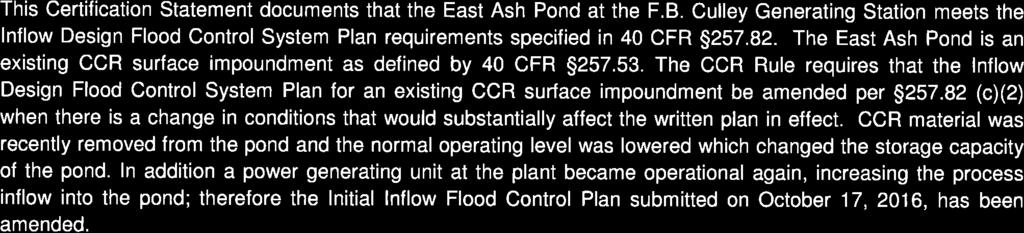
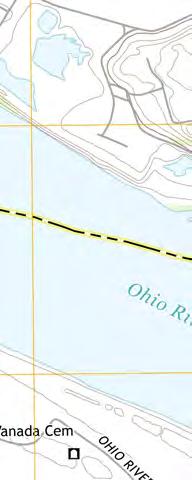
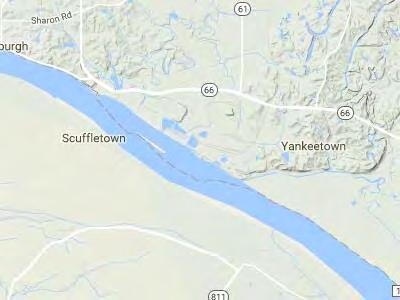
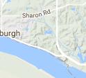
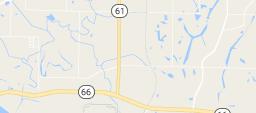
6 AECOM CCR Certification: Amended Inflow Design Flood Control System Plan for the East Ash Pond at the F.B. Culley Generating Station 1-1 Introduction 1 Introduction 1.1 Purpose of This Report The purpose of the Amended Inflow Design Flood Control System Plan (Inflow Flood Control Plan) is to document that the requirements specified in 4 code of Federal Regulations (CFR) have been met to support the certification required under each of the applicable regulatory provisions for the F.B. Culley Generating Station (Culley) East Ash Pond. The East Ash Pond is an existing Coal Combustion Residuals (CCR) surface impoundment as defined by 4 CFR The CCR Rule requires that the, Inflow Flood Control Plan for an existing CCR surface impoundment be amended per (c)(2) when there is a change in conditions that would substantially affect the written plan in effect. CCR was recently removed from the pond and the normal operating level of the pond was lowered which changed the storage capacity of the pond. In addition, a power generating unit at the plant returned to operation, increasing the process inflow into the pond. Therefore, the Inflow Flood Control Plan has been amended to reflect these changes. The East Ash Pond has been evaluated to determine whether the inflow design flood control system requirements are met. The following table summarizes the documentation required within the CCR Rule and the sections that specifically respond to those requirements of this plan. Table 1-1 CCR Rule Cross Reference Table Report Section Title CCR Rule Reference 4.1 Inflow Analysis (a)(1) 4.2 Outflow Analysis (a)(2) 4.3 Inflow Design Flood (a)(3) 4.4 Discharge handled in accordance with (b) Analyses completed for the hydrologic and hydraulic assessments of the East Ash Pond are described in this report. Data and analyses results in the following sections are based on spillway design information shown on design drawings, topographic surveys, information about operational and maintenance procedures provided by Southern Indiana Gas & Electric Company, dba Vectren Power Supply, Inc. (SIGECO), and limited field measurements collected by AECOM. The analysis approach and results of the hydrologic and hydraulic analyses presented in the following sections were used by AECOM to confirm that the East Ash Pond meets the hydrologic and hydraulic capacity requirements of the rules referenced above for CCR surface impoundments. 1.2 Brief Description of Impoundment The Culley station is located in Warrick County, Indiana, southeast of Newburgh, Indiana, and is owned and operated by SIGECO. The station is located along the north bank of the Ohio River and the west bank of the Little Pigeon Creek along the southeast portion of the site. The Culley station consists of two CCR surface February 1, 217
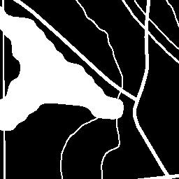
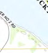
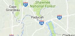
7 AECOM CCR Certification: Amended Inflow Design Flood Control System Plan for the East Ash Pond at the F.B. Culley Generating Station 1-2 Introduction impoundments, identified as the West Pond and East Ash Pond. The East Ash Pond is located directly east of the station and is approximately 1 acres in size. The East Ash Pond was commissioned in or around 1971 and operates as an unlined CCR impoundment. Earthen embankments were constructed along the south and east sides of the impoundment. Structural fill used for the original construction of the Culley station in the 195 s borders the impoundment to the west side, and west end of the north side. The east embankment intersects a natural hillside on the east end of the north side of the impoundment. The embankment is approximately 1,2 feet long, 3 feet high, and has 2.4 to 1 (horizontal to vertical) exterior side slopes covered with grassy vegetation. Interior side slopes varied from 2.5 to 1 (horizontal to vertical) to 2 to 1 (horizontal to vertical) for the upper and lower portion of the embankment, respectively. The embankment crest elevation varies from feet 1 to feet and has a crest width of approximately 15 feet. Within the west side structural fill, along the plant side of the East Ash Pond, there is a gravel layer forming the top of the embankment. This was uncovered during excavation of CCR material. The base elevation of the gravel is at approximately 392 feet. The surface area of the impoundment is approximately 9.8 acres. The recent construction activity has reshaped the interior of the pond to form two smaller ponds within the East Ash Pond, separated by a berm 26 feet wide and 33 feet long with a 24-inch culvert connecting them. The ponding water has a surface area of approximately 7.26 acres and has a normal operating water level of 386 feet. A site Location Map showing the area surrounding the station is in Figure 1 of Appendix A. Figure 2 in Appendix A presents the F.B. Culley Generating Station Site Map Inflow from Plant Operations and Stormwater Runoff Flue gas desulphurization (FGD) blowdown material is currently sluiced from the plant into the eastern side of the impoundment as well as clarified river raw water for a total inflow rate of approximately.2 cubic feet per second (cfs). Unit 2 and 3 discharges from air heater wash, the pyrite systems, boiler water, and flow from the west yard sump pump flow into the western part of the impoundment at a rate of 2.1 cfs. The water is discharged from the impoundment via pumping station through a permitted National Pollutant Discharge Elimination System (NPDES) outfall, identified as Internal Outfall 21, at a rate of.42 cfs. In addition to rainfall directly into the impoundment, there are upstream areas that contribute runoff to the impoundment. The grassy areas to the north drain directly to the East Ash Pond through ditches and culverts. The rest of the site drainage areas, including the plant area, coal pile, and grassy areas to the northwest of the site drain to the inactive West Pond where collected stormwater in the pond is pumped to the West Pond pump station and is discharged to the Ohio River through permitted Outfall 1. The total drainage area to the East Ash Pond impoundment is approximately 3.69 acres Outlet Structures Water discharges from the impoundment through a pump station located at the west side of the East Ash Pond. The pond pump station consists of two, CP 317 LT 3~63 model 5,4 gpm submersible pumps manufactured by Flygt. The 1-inch pump discharge connects to a manhole on an 84-inch pipe that discharges to an underground discharge tunnel, which collects stormwater and other clean process water from throughout the Culley station and then discharges to the Ohio River through NPDES permitted Outfall 1. 1 Unless otherwise noted, all elevations in this report are in the NAVD88 datum. February 1, 217
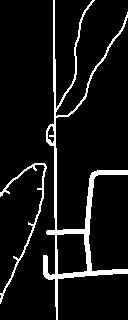
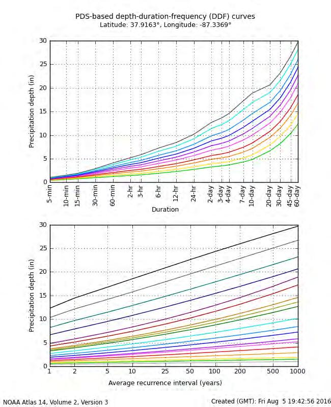
8 AECOM CCR Certification: Amended Inflow Design Flood Control System Plan for the East Ash Pond at the F.B. Culley Generating Station 2-1 Hydrologic Analysis 2 Hydrologic Analysis 2.1 Design Storm The East Ash Pond has been categorized as a Significant hazard potential CCR impoundment, which requires that the inflow design flood is the 1,-year return frequency design storm event. The full analysis for this classification determination is included in the CCR Certification: Initial Hazard Potential Classification for the East Ash Pond at the F.B. Culley Generating Station. 2.2 Rainfall Data The rainfall information used in the analysis was based on the National Oceanic and Atmospheric Administration (NOAA) Atlas 14, Volume 2, Version 3 which provides rainfall data for storm events with average recurrence intervals ranging from 1 to 1, years and durations ranging from 5 minutes to 6 days. The design storm rainfall depth, obtained from the NOAA website, is 1.2 inches for the 24-hour, 1,-year storm. The Indiana Huff, Third Quartile rainfall distribution was used by AECOM and is appropriate to use for storms up to the 1,- year, 24-hr flood at the project site. 2.3 Runoff Computations The drainage areas for the East Ash Pond were estimated using a computer-aided design (CAD) analysis of aerial survey conducted in 211 and topographic ground surveys completed in 215 by Three I Design and a drone topographic survey completed in 216 by the Lochmueller Group. The grassy areas to the north drain directly to the East Ash Pond. The total drainage area to the East Ash Pond is approximately 3.69 acres. See Appendix A for the Drainage Area Maps. Runoff was calculated using the SCS Curve Number Method, where curve numbers (CN) were assigned to each subcatchment based on the type of land cover and soil type present. Using the USDA Natural Resources Conservation Service (NRCS) Web Soil Survey, the soil type of the site was selected as hydrologic soil group B. CN values for the land cover were selected from the CN Table available in HydroCAD. This data was obtained from the SCS NRCS Technical Release-55 (TR-55) publication. Ash, Industrial Areas, Water Surface, 5-75% grass cover, and >75% grass covers that are located on site were estimated to have CN values of 88, 88, 98, 69 and 61 respectively. A composite CN was calculated for each subcatchment area by summing the products of each CN multiplied by its percentage of the total area. The time of concentration is commonly defined as the time required for runoff to travel from the most hydrologically distant point to the point of collection. Calculations for the time of concentration for each subwatershed were performed in HydroCAD and are included in Appendix B. Stormwater runoff from the 1,-year event into the impoundment has a peak inflow of 4.35 cfs and total inflow volume of acre-feet. Refer to Appendix B for HydroCAD results. February 1, 217
9 AECOM CCR Certification: Amended Inflow Design Flood Control System Plan for the East Ash Pond at the F.B. Culley Generating Station 3-1 Hydraulic Analysis 3 Hydraulic Analyses 3.1 Process Flows Process water containing ash maximum flow rate from the plant into the East Ash Pond is of 2.3 cubic feet per second (cfs) or 1.45 million gallons per day (MGD). 3.2 Storage Capacity The storage volume for the East Ash Pond was evaluated using a computer-aided design (CAD) analysis to estimate the volume of the pond under the present conditions. A survey was performed on November 3, 216 to verify the available volume within the East Ash Pond after ash removal operations. Initially, the lowest elevation within the embankment surrounding the pond was used as the overtopping elevation. The excavation of CCR material uncovered a gravel layer within the structural fill forming the west side of the East Ash Pond with the base of the gravel layer at approximate elevation 392 feet. This elevation was used as the overtopping elevation to minimize the chance of stormwater migrating into this rock layer. The volume of storage was calculated by estimating the incremental storage volume present for each 1 foot elevation within the updated topographic surface supplied by SIGECO representatives in 216. The incremental storage volume was then used to calculate a cumulative storage volume and was input into HydroCAD. The volume of storage provided by the two interconnected ponds within the East Ash Pond from normal pool elevation of 386 feet to the base of gravel seam located along the west side of the pond at an approximate elevation of 392 feet is approximately acre-feet. This volume was determined with the knowledge that the two ponds within the East Ash Pond basin are connected by a single 24-inch culvert, allowing storm volumes to be shared by the two ponds. Refer to Appendix B for further storage volumes details. 3.3 Discharge Analysis A hydraulic model was created in HydroCAD 1. to assess the capacity of the pond to store and convey the storm flows. HydroCAD has the capability to evaluate each pond within the network, to respond to variable tailwater, pumping rates, permit flow loops, and reversing flows. HydroCAD routing calculations reevaluate the pond systems discharge capability at each time increment, making the program an efficient and dynamic tool for this evaluation. The analyzed scenario assumes the starting water surface elevation of the interconnected ponds within the East Ash Pond is 386 feet, the normal operating level of the ponds. For the purposes of this analysis, the East Ash Pond was analyzed as if neither discharge pump within the pump station was operational. This represents a worst case scenario and the East Ash Pond must be capable of storing the design storm. As such, the facility would not cause a discharge of pollutants into waters of the United States that is in violation of the requirements of the NPDES under section 42 of the Clean Water Act. February 1, 217
10 AECOM CCR Certification: Amended Inflow Design Flood Control System Plan for the East Ash Pond at the F.B. Culley Generating Station 4-1 Results 4 Results The hydrologic and hydraulic conditions of the East Ash Pond were modeled with the peak discharge of the 1,-year storm event. Regulatory Citation: 4 CFR (a); The owner or operator of an existing or new CCR surface impoundment or any lateral expansion of a CCR of a CCR surface impoundment must design, construct, operate, and maintain an inflow design flood control system as specified in paragraphs (a)(1) and (2) of this section. 4.1 Inflow Analysis Regulatory Citation: 4 CFR (a); (1) The inflow design flood control system must adequately manage flow into the CCR unit during and following the peak discharge of the inflows design flood specified in paragraph (3). Background and Assessment The East Ash Pond collects runoff from only a small area of the Culley station site and this runoff drains to the pond through sheet flow, overland ditching, and culverts located on the northwest side of the pond. These runoff volumes, in addition to the rainfall falling within the pond itself, and the plant process flows, produce the total inflow to the East Ash Pond. Using the HydroCAD model, the total inflow was stored within the East Ash Pond to evaluate the resulting peak water surface elevation. Table 4-1 summarizes the maximum water surface elevation of the ponds within the East Ash Pond prior to and after the inflow design flood. Table Summary of Hydrologic and Hydraulic Analysis 1,-Year, 24-Hour Storm CCR Unit Beginning WSE 1 (feet) Peak WSE (feet) Base of Gravel within West Embankment (feet) Freeboard Above Peak WSE (feet) East Ash Pond Notes: 1 WSE = Water Surface Elevation Conclusion and Recommendation As there is adequate storage within the East Ash Pond to manage the inflow design flood, there is no anticipated overtopping of the East Ash Pond embankment, which meets the requirements in (a)(1). February 1, 217
11 AECOM CCR Certification: Amended Inflow Design Flood Control System Plan for the East Ash Pond at the F.B. Culley Generating Station 4-2 Results 4.2 Outflow Analysis Regulatory Citation: 4 CFR (a); (2) The inflow design flood control system must adequately manage flow from the CCR unit to collect and control the peak discharge resulting from the inflow design flood specified in paragraph (3) of this section. Background and Assessment The East Ash Pond currently collects stormwater from a small area of the site including the grass areas to the north routed through a series of ditches and culverts, as well as any rainfall that falls directly within the perimeter embankments. The rain falling within the pond, the stormwater runoff directly draining to the pond, and the plant process inflows, combine to produce the total inflow to the East Ash Pond. The HydroCAD model was used to estimate the peak water surface elevation within the East Ash Pond during the design storm when the Ohio River is experiencing a 1-year flood. Table 4-2 summarizes the peak flowrates and velocities through each of the outlet devices. Table Summary of Outlet Devices 1,-Year, 24-Hour Storm Invert Elevation Peak Flowrate Velocity at Peak Flowrate Outlet Device Type and Size (feet) (cfs) (fps) Pump Station - Outlet 2 pump 54 GPM; CP 317 LT 3~ N/A N/A Base of Gravel within West Embankment Weir Conclusion and Recommendation In the case where the East Ash Pond pump station is not operational, AECOM recommends the Culley station provide pumping capacity equal to the existing lift station pumps by means of providing supplemental pumps or bringing the existing lift station pumps online within 48-hours. As the East Ash Pond can store the design storm from the plant without utilizing its pump station and without the peak water surface elevation reaching the base of the gravel along the west embankment, the pond meets the requirements in (a)(2). February 1, 217
12 AECOM CCR Certification: Amended Inflow Design Flood Control System Plan for the East Ash Pond at the F.B. Culley Generating Station 4-3 Results 4.3 Inflow Design Flood Regulatory Citation: 4 CFR (a); (3) The inflow design flood is: o o o o (i) For a high hazard potential CCR surface impoundment, as determined under (a)(2), the probable maximum flood; (ii) For a significant hazard potential CCR surface impoundment, as determined under (a)(2), the 1,-year flood; (iii) For a low hazard potential CCR surface impoundment, as determined under (a)(2), the 1-year flood; or (iv) For an incised CCR surface impoundment, the 25-year flood. Background and Assessment The calculations for the inflow design flood are based on the hazard potential given to the impoundment. The different classifications of the impoundment hazard potential are high, significant, and low. Conclusion and Recommendation As the impoundment was given a significant hazard potential, the 1, year design storm was utilized in the analysis, which meets the requirements in (a)(3). 4.4 Discharge Regulatory Citation: 4 CFR (b); Discharge from the CCR unit must be handled in accordance with the surface water requirements under: Background and Assessment The East Ash Pond was modeled without a working pump station to simulate a worst case scenario. As such, there is no discharge from the pond in this model scenario. However, during normal operating conditions the discharge from the East Ash Pond pump station is conveyed through a 1-inch pipe that connects to a manhole on an 84-inch pipe and discharges to an underground discharge tunnel, which also collects discharge water from the cooling water system and various other clean discharge water sources located throughout the power plant. The underground discharge tunnel runs by the basement of Unit 2 within the power plant and discharges directly to the Ohio River through NPDES Permitted Outfall 1. The Ohio River was modeled at the FEMA 1 year flood elevation of The discharge must meet the requirements of the NDPES under section 42 of the Clean Water Act to meet the CCR rule. Conclusion and Recommendation No modifications are necessary or recommended to this unit for compliance with the CCR Rule. Runoff discharges from the site through a permitted NPDES outfall. As per the current NPDES permit, all discharged water is tested for pollutants to meet the minimum regulatory requirements of the permit, and thereby meets the requirements in (b). February 1, 217
13 AECOM CCR Certification: Amended Inflow Design Flood Control System Plan for the East Ash Pond at the F.B. Culley Generating Station 5-1 Conclusions 5 Conclusions The Inflow Flood Control Plan of the East Ash Pond adequately manages flow into the CCR unit during and following the peak discharge of the 1,-year frequency storm event inflow design flood. The inflow design flood control system of the East Ash Pond adequately manages flow from the CCR unit to collect and control the peak discharge resulting from the 1,-year frequency storm event inflow design flood. Therefore, the East Ash Pond meets the requirements for certification. In the case where the East Ash Pond pump station is not operational, AECOM recommends that the Culley Generating Station provide pumping capacity equal to the existing lift station pumps by means of providing supplemental pumps or bringing the existing lift station pumps online within 48-hours. The contents of this report, specifically Sections 1 through 4, represent the Amended Inflow Design Flood Control System Plan for this site. February 1, 217


14
15 AECOM CCR Certification: Amended Inflow Design Flood Control System Plan for the East Ash Pond at the F.B. Culley Generating Station 7-1 Limitations 7 Limitations Background information, design basis, and other data which AECOM has used in preparing this report have been furnished to AECOM by SIGECO. AECOM has relied on this information as furnished, and is not responsible for the accuracy of this information. Our recommendations are based on available information from previous and current investigations. These recommendations may be updated as future investigations are performed. The conclusions presented in this report are intended only for the purpose, site location, and project indicated. The recommendations presented in this report should not be used for other projects or purposes. Conclusions or recommendations made from these data by others are their responsibility. The conclusions and recommendations are based on AECOM s understanding of current plant operations, maintenance, stormwater handling, and ash handling procedures at the station, as provided by SIGECO. Changes in any of these operations or procedures may invalidate the findings in this report until AECOM has had the opportunity to review the findings, and revise the report if necessary. This hydrologic and hydraulic analysis was performed in accordance with the standard of care commonly used as state-of-practice in our profession. Specifically, our services have been performed in accordance with accepted principles and practices of the engineering profession. The conclusions presented in this report are professional opinions based on the indicated project criteria and data available at the time this report was prepared. Our services were provided in a manner consistent with the level of care and skill ordinarily exercised by other professional consultants under similar circumstances. No other representation is intended. While the CCR unit adequately manages the inflow design flood, SIGECO must perform routine maintenance on the CCR unit to continually manage flood events without failure. The pump station should be cleared of debris that could block or damage the device. The two ponds within the East Ash Pond should maintain an operating water surface elevation at or below 386 feet. Pipes, intake structures, and pumps should be monitored and repaired if deterioration or deformation occurs. All grass lined slopes should be examined for erosion and repaired if damaged. Rip rap lined channels should be inspected for stones that have shifted or bare spots that have formed. Replace rip rap as needed. Additionally, in the case where the East Ash Pond pump station is not working, SIGECO shall provide pumping capacity equal to the existing lift station pumps by means of providing supplemental pumps or bringing the existing lift station pumps online within 48-hours. February 1, 217
16 AECOM CCR Certification: Amended Inflow Design Flood Control System Plan for the East Ash Pond at the F.B. Culley Generating Station Appendix A Figures Figure 1 Location Map Figure 2 Site Map Figure 3 Drainage Area Map February 1, 217


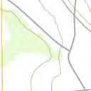


17 94 Amberglen Boulevard Austin, TX (phone) (fax) SOUTHERN INDIANA GAS AND ELECTRIC COMPANY dba VECTREN POWER SUPPLY, INC. One Vectren Square Evansville, IN (phone) F.B. CULLEY GENERATING STATION NEWBURGH, IN CCR ANNUAL INSPECTION EAST ASH POND ISSUED FOR CERTIFICATION ISSUED FOR BIDDING DATE BY ISSUED FOR CONSTRUCTION DATE BY REVISIONS NO. DESCRIPTION DATE F.B. CULLEY GENERATING STATION CULLEY EAST ASH POND AECOM PROJECT NO: DRAWN BY: DESIGNED BY: CHECKED BY: DATE CREATED: PLOT DATE: SCALE: ACAD VER: SHEET TITLE MJC MJC TLE 1/1/217 2/9/217 1" = 1' 214 LOCATION MAP SCALE IN FEET FIGURE 1
18 94 Amberglen Boulevard Austin, TX (phone) (fax) SOUTHERN INDIANA GAS AND ELECTRIC COMPANY dba VECTREN POWER SUPPLY, INC. One Vectren Square Evansville, IN (phone) F.B. CULLEY GENERATING STATION NEWBURGH, IN CCR ANNUAL INSPECTION EAST ASH POND CULLEY WEST ASH POND ISSUED FOR CERTIFICATION ISSUED FOR BIDDING DATE BY ISSUED FOR CONSTRUCTION DATE BY COAL PILE REVISIONS NO. DESCRIPTION DATE CULLEY GENERATING STATION OHIO RIVER CULLEY EAST ASH POND LITTLE PIGEON CREEK AECOM PROJECT NO: DRAWN BY: DESIGNED BY: CHECKED BY: DATE CREATED: PLOT DATE: SCALE: ACAD VER: SHEET TITLE MJC MJC TLE 1/1/217 2/9/217 1" = 2' SITE MAP SCALE IN FEET FIGURE 2
 SUBC")
19 94 Amberglen Boulevard Austin, TX (phone) (fax) SUBCATCHMENT 4 AREA = 11.1 ACRES SUBCATCHMENT 6 AREA = 3.8 ACRES SOUTHERN INDIANA GAS AND ELECTRIC COMPANY dba VECTREN POWER SUPPLY, INC. One Vectren Square Evansville, IN (phone) SUBCATCHMENT 3 AREA = 12.3 ACRES F.B. CULLEY GENERATING STATION NEWBURGH, IN CCR CERTIFICATION EAST ASH POND CULLEY WEST ASH POND SUBCATCHMENT 7 AREA = 24.7 ACRES SUBCATCHMENT 2 AREA = 1.2 ACRES SUBCATCHMENT 9 AREA = 4.9 ACRES ISSUED FOR CERTIFICATION ISSUED FOR BIDDING ISSUED FOR CONSTRUCTION DATE DATE BY BY COAL PILE SUBCATCHMENT 8 AREA = 1.9 ACRES REVISIONS NO. DESCRIPTION DATE CULLEY GENERATING STATION SUBCATCHMENT 1 AREA = 15.8 LITTLE PIGEON CREEK AECOM PROJECT NO: DRAWN BY: DESIGNED BY: CHECKED BY: DATE CREATED: PLOT DATE: SCALE: MJC MJC TLE 8/24/216 4/22/216 AS SHOWN ACAD VER: OHIO RIVER CULLEY EAST ASH POND SUBCATCMENT 5 AREA = 11. ACRES SHEET TITLE SITE MAP SCALE IN FEET FIGURE 3
20 AECOM CCR Certification: Initial Inflow Design Flood Control System Plan for the East Ash Pond at the F.B. Culley Generating Station Appendix B Hydrologic and Hydraulic Calculations NOAA Precipitation Data Soils Data Water Balance HydroCAD Output Attorney Client Privileged February 217
21 AECOM Initial Inflow Design Flood Control System Plan For the Culley East Ash Pond at the F.B. Culley Generating Station NOAA Precipitation Data Attorney Client Privileged February 217

22


23


24
25
26 AECOM Initial Inflow Design Flood Control System Plan For the Culley East Ash Pond at the F.B. Culley Generating Station Soils Data Attorney Client Privileged February 217

27 87 2' 6'' W Hydrologic Soil Group Warrick County, Indiana 87 18' 56'' W 37 55' 3'' N ' 3'' N 37 54' 27'' N 37 54' 27'' N ' 6'' W N Map Scale: 1:7,78 if printed on A landscape (11" x 8.5") sheet. Meters Feet Map projection: Web Mercator Corner coordinates: WGS84 Edge tics: UTM Zone 16N WGS ' 56'' W Natural Resources Conservation Service Web Soil Survey National Cooperative Soil Survey 11/3/215 Page 1 of 4
28 Hydrologic Soil Group Warrick County, Indiana MAP LEGEND MAP INFORMATION Area of Interest (AOI) Area of Interest (AOI) Soils Soil Rating Polygons A A/D B B/D C C/D D Not rated or not available Soil Rating Lines A A/D B B/D C C/D D Not rated or not available Soil Rating Points A A/D B B/D C C/D D Not rated or not available Water Features Streams and Canals Transportation Rails Interstate Highways US Routes Major Roads Local Roads Background Aerial Photography The soil surveys that comprise your AOI were mapped at 1:15,8. Warning: Soil Map may not be valid at this scale. Enlargement of maps beyond the scale of mapping can cause misunderstanding of the detail of mapping and accuracy of soil line placement. The maps do not show the small areas of contrasting soils that could have been shown at a more detailed scale. Please rely on the bar scale on each map sheet for map measurements. Source of Map: Natural Resources Conservation Service Web Soil Survey URL: Coordinate System: Web Mercator (EPSG:3857) Maps from the Web Soil Survey are based on the Web Mercator projection, which preserves direction and shape but distorts distance and area. A projection that preserves area, such as the Albers equal-area conic projection, should be used if more accurate calculations of distance or area are required. This product is generated from the USDA-NRCS certified data as of the version date(s) listed below. Soil Survey Area: Warrick County, Indiana Survey Area Data: Version 18, Sep 11, 215 Soil map units are labeled (as space allows) for map scales 1:5, or larger. Date(s) aerial images were photographed: Oct 3, 211 Oct 4, 211 The orthophoto or other base map on which the soil lines were compiled and digitized probably differs from the background imagery displayed on these maps. As a result, some minor shifting of map unit boundaries may be evident. Natural Resources Conservation Service Web Soil Survey National Cooperative Soil Survey 11/3/215 Page 2 of 4
29 Hydrologic Soil Group Warrick County, Indiana Hydrologic Soil Group Hydrologic Soil Group Summary by Map Unit Warrick County, Indiana (IN173) Map unit symbol Map unit name Rating Acres in AOI Percent of AOI AfB2 Alford silt loam, 2 to 6 percent slopes, eroded AfC Alford silt loam, 6 to 12 percent slopes AfC3 Alford silt loam, 6 to 12 percent slopes, severely eroded AfD3 Alford silt loam, 12 to 18 percent slopes, severely eroded B % B % B % B % Du Dumps, mine % HeA Henshaw silt loam, to 2 percent slopes, rarely flooded C/D % Hu Huntington silt loam, frequently flooded MuB2 Muren silt loam, 2 to 6 percent slopes, eroded Ne Newark silty clay loam, frequently flooded B % B/D % B/D 1.4.8% W Water % Wa WbA WeD WeD3 WeE2 Wakeland silt loam, frequently flooded Weinbach silt loam, to 2 percent slopes Wellston silt loam, 12 to 18 percent slopes Wellston silt loam, 12 to 18 percent slopes, severely eroded Wellston silt loam, 18 to 25 percent slopes, eroded WhA Wheeling silt loam, to 2 percent slopes WhB2 Wheeling silt loam, 2 to 6 percent slopes, eroded Wo Woodmere silty clay loam, occasionally flooded B/D % C/D..% B % B % B % B.5.3% B.1.1% C.2.1% Totals for Area of Interest % Natural Resources Conservation Service Web Soil Survey National Cooperative Soil Survey 11/3/215 Page 3 of 4
30 Hydrologic Soil Group Warrick County, Indiana Description Hydrologic soil groups are based on estimates of runoff potential. Soils are assigned to one of four groups according to the rate of water infiltration when the soils are not protected by vegetation, are thoroughly wet, and receive precipitation from long-duration storms. The soils in the United States are assigned to four groups (A, B, C, and D) and three dual classes (A/D, B/D, and C/D). The groups are defined as follows: Group A. Soils having a high infiltration rate (low runoff potential) when thoroughly wet. These consist mainly of deep, well drained to excessively drained sands or gravelly sands. These soils have a high rate of water transmission. Group B. Soils having a moderate infiltration rate when thoroughly wet. These consist chiefly of moderately deep or deep, moderately well drained or well drained soils that have moderately fine texture to moderately coarse texture. These soils have a moderate rate of water transmission. Group C. Soils having a slow infiltration rate when thoroughly wet. These consist chiefly of soils having a layer that impedes the downward movement of water or soils of moderately fine texture or fine texture. These soils have a slow rate of water transmission. Group D. Soils having a very slow infiltration rate (high runoff potential) when thoroughly wet. These consist chiefly of clays that have a high shrink-swell potential, soils that have a high water table, soils that have a claypan or clay layer at or near the surface, and soils that are shallow over nearly impervious material. These soils have a very slow rate of water transmission. If a soil is assigned to a dual hydrologic group (A/D, B/D, or C/D), the first letter is for drained areas and the second is for undrained areas. Only the soils that in their natural condition are in group D are assigned to dual classes. Rating Options Aggregation Method: Dominant Condition Component Percent Cutoff: None Specified Tie-break Rule: Higher Natural Resources Conservation Service Web Soil Survey National Cooperative Soil Survey 11/3/215 Page 4 of 4
31 AECOM Initial Inflow Design Flood Control System Plan For the Culley East Ash Pond at the F.B. Culley Generating Station Water Balance Attorney Client Privileged February 217
32 FB Culley Final Conditions Process Pond Area Source Flow Unit 3 Area Unit 3 Air Heater.1578 mgd Unit 3 Pyrite System mgd FDG WW Mercury System.951 mgd Clarified River Raw Water.3541 mgd West Yard Sump Pump.7916 mgd Unit 3 Oil trap Tank mgd Unit 3 Boiler Sump Pumps.1726 mgd Unit 2 Area Unit 2 Air Heater Wash.1578 mgd Unit 2 Pyrite System.663 mgd Unit 2 Boiler Seal Trough and Sump Pumps.1425 mgd To main Pond: To Gypsum Pond: TOTAL PROCESS FLOW mgd TOTAL PROCESS FLOW.1351 mgd gallons/day 1351 gallons/day cft/day cft/day cfs cfs Round up: 2.1 cfs Round up:.2 cfs
33 AECOM Initial Inflow Design Flood Control System Plan For the Culley East Ash Pond at the F.B. Culley Generating Station Other Supporting Documentation Attorney Client Privileged February 217
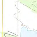
34 CP 317 LT 3~ 63 (Discontinued) Performance curv e Pump [ft] Head Motor Discharge Flange Diameter 9 13/16 inch Motor # C AA-W 25hp Power factor Inlet diameter 25 mm Stator variant 37 1/1 Load.81 Impeller diameter /16" Frequency 6 Hz 3/4 Load.75 Number of blades 2 Rated voltage 46 V 1/2 Load.64 Throughlet diameter 4 inch Number of poles 6 Phases 3~ Efficiency Rated power 25 hp 1/1 Load 85. % Rated current 34 A 3/4 Load 84.5 % Starting current 219 A 1/2 Load 81.5 % Rated speed 117 rpm ft % Eff mm [%] 6 4 Efficiency Total efficiency 71.3 % 6.8 % mm [hp] [ft] Shaft power P2 Power input P1 NPSH-values 2177 US g.p.m hp 63 3mm (P1) 24.2 hp 63 3mm (P2) 63 3mm 13.3 ft [US g.p.m.] Water, pure Curve ISO Project Project ID Created by Created on Last update
![CP 317 LT 3~ 63 (Discontinued) Duty Analysis [ft] 51 5 49 48 47 46 45 44 43 42 41 4 39 38 37 36 35 34 33 32 31 3 29 28 27 26 25 24 23 22 21 2 19 18 17 16 15 14 13 12 11 1 9 8 7 6 5 4 3 2 1 Head 2177](/docs-images/92/108346204/images/35-0.jpg "US g.p.m. 1 Eff. 76.4% 63 3mm 31.3 ft 5 1 15 2 25 3 35 4 45 5 55 [US g.p.m.] Water, pure Curve issue 6 Curve ISO Indiv idual pump Total Pumps running Specific /System Flow Head Shaft power Flow Head Shaft power Pump eff.")
35 CP 317 LT 3~ 63 (Discontinued) Duty Analysis [ft] Head 2177 US g.p.m. 1 Eff. 76.4% 63 3mm 31.3 ft [US g.p.m.] Water, pure Curve issue 6 Curve ISO Indiv idual pump Total Pumps running Specific /System Flow Head Shaft power Flow Head Shaft power Pump eff. energy NPSHre US g.p.m ft 24.2 hp 218 US g.p.m ft 24.2 hp 71.3 % 162 kwh/us MG 13.3 ft Project Project ID Created by Created on Last update
36
37
38
39
40
41 AECOM Initial Inflow Design Flood Control System Plan For the Culley East Ash Pond at the F.B. Culley Generating Station HydroCAD Output Report Attorney Client Privileged February 217

42 AECOM Initial Inflow Design Flood Control System Plan For the Culley East Ash Pond at the F.B. Culley Generating Station The East Ash Pond was constructed using structural fill on the west side and west end of the north side of the impoundment. The east embankment intersects a natural hillside on the east end of the north side of the impoundment. The embankment is approximately 1,2 feet long, 3 feet high, and has 2.4 to 1 (horizontal to vertical) exterior side slopes covered with grassy vegetation. Interior side slopes varied from 2.5 to 1 (horizontal to vertical) to 2 to 1 (horizontal to vertical) for the upper and lower portion of the embankment, respectively. The embankment crest elevation varies from feet 1 to feet and has a crest width of approximately 15 feet. The surface area of the impoundment is approximately 9.8 acres. Within the pond, there are two separate ponds that are being utilized for treatment and separation of CCR material within the pond. The diagram below depicts the two pond scenario conditions within the Culley East Pond as the HydroCAD model was setup and analyzed for the certification. The two interconnected ponds include ponds 2P and 8P. These 2 ponds are connected with a single 24 inch culvert under the berm separating the two ponds. The culvert is used to equalize the water surface elevations within the ponds during rainfall events and to prevent overtopping. The pump station wet well is located on the west side of the main treatment pond and discharges through a NPDES permitted outfall to the Ohio River. The subcatchments for each pond were measured using a computer-aided design (CAD) analysis to calculate the area of drainage to each pond based on the most recent topographic survey. The runoff computations were completed the SCS Curve Number Method, where curve numbers (CN) were assigned to each subcatchment based on the type of land cover and soil type present. Using the USDA Natural Resources Conservation Service (NRCS) Web Soil Survey, the soil type of the site was selected 1 unless otherwise noted, all elevations in this report are in the NAVD88 datum Attorney Client Privileged February 217
43 AECOM Initial Inflow Design Flood Control System Plan For the Culley East Ash Pond at the F.B. Culley Generating Station as hydrologic soil group B. CN values for the land cover were selected from the CN Table available in HydroCAD. As all of the subcatchments except 9S are within the East Ash Pond, a CN value of 98 was specified as water surface. This provides the most conservative runoff values. The storage capacity for each pond was evaluated using CAD to estimate the volume of the ponds under the conditions presented in the latest topographic survey dated November 3th, 216. The volume of storage was calculated by estimating the incremental storage volume present for each 1 foot elevation within the updated topographic surface. The incremental storage volume was then used to calculate a cumulative storage volume and was input into HydroCAD. This volume was determined with the assumption that the two ponds will be maintained with an operating water surface elevation at or below 386 feet. A hydraulic model was created in HydroCAD 1. to assess the capacity of the ponds to store and convey the storm flows. HydroCAD has the capability to evaluate each pond within the network, to respond to variable tailwater, pumping rates, permit flow loops, and reversing flows. HydroCAD routing calculations reevaluate the ponds systems discharge capability at each time increment, making the program an efficient and dynamic tool for this evaluation. The East Ash Pond pump station is the only discharge point for the East Ash Pond. For the purposes of this analysis, the East Ash Pond was analyzed as if neither pump within the pump station was operational. This represents a worst case scenario. As such, the ponds within the East Ash Pond must store the design storm. The detailed output from the HydroCAD model is presented in the following pages. Attorney Client Privileged February 217

44 7S Subcatchment 7 6S Subcatchment 6 4S Subcatchment 4 2R Ditch 2 3S 1P Subcatchment 3 Culley West Pond 8S 1R Ditch 1 2S Subcatchment 2 Subcatchment 8 9S Subcatchment 9 1S Subcatchment 1 17S 2P Main Treatment Pond Drainage Area 3P Ohio River Main Treatment Pond 13S 8P Gypsum Pond Drainage Area Gypsum Pond Subcat Reach Pond Link Routing Diagram for Culley East 217 Certifying FINAL Conditions_rev_starting WSE 386,
45 Culley East 217 Certifying FINAL Conditions_rev_starting WSE 386 Page 2 Area (acres) CN Description (subcatchment-numbers) Area Listing (all nodes) >75% Grass cover, Good, HSG B (2S) % Grass cover, Fair, HSG B (3S, 4S, 6S, 9S) Urban industrial, 72% imp, HSG B (1S, 2S, 8S) Water Surface, HSG B (7S, 13S, 17S) TOTAL AREA
46 Culley East 217 Certifying FINAL Conditions_rev_starting WSE 386 Page 3 Area (acres) Soil Group Subcatchment Numbers Soil Listing (all nodes). HSG A HSG B 1S, 2S, 3S, 4S, 6S, 7S, 8S, 9S, 13S, 17S. HSG C. HSG D. Other TOTAL AREA
47 Culley East 217 Certifying FINAL Conditions_rev_starting WSE 386 Page 4 HSG-A (acres) HSG-B (acres) HSG-C (acres) Ground Covers (all nodes) HSG-D (acres) Other (acres) Total (acres) Ground Cover Subcatchment Numbers % Grass cover, Fair 3S, 4S, 6S, 9S >75% Grass cover, Good 2S Urban industrial, 72% imp 1S, 2S, 8S Water Surface 7S, 13S, 17S TOTAL AREA
48 Culley East 217 Certifying FINAL Conditions_rev_starting WSE 386 Page 5 Line# Node Number In-Invert (feet) Out-Invert (feet) Pipe Listing (all nodes) Length (feet) Slope (ft/ft) n Diam/Width (inches) Height (inches) Inside-Fill (inches) 1 2P P
49 Culley East 217 Certifying FINAL Conditions_rev_starting WSE 386 Page 6 Line# Node Number Notes Notes Listing (all nodes) 1 1S Acre number found using LIDAR data from 212 and measuring areas in AutoCAD. CN used for class B soils and urban industrial was Time of concentration data was determined using LIDAR data from 212 and measuring lengths in AutoCAD. 3 To complete time of concentration, a method of sheet flow, shallow flow, or channel flow is needed. These are estimated using LIDAR data. Other things that are needed include a surface description, length of flow, manning's number, land slope, and P2 are needed. The program then computes a Tc. 4 2S Acre number found using LIDAR data from 212 and measuring areas in AutoCAD. CN used for grass cover over 75% for class B soils is 61 and a CN of 88 was used for urban industrial. Each CN was used for half of the site. 5 Time of concentration data was determined using LIDAR data from 212 and measuring lengths in AutoCAD. 6 To complete time of concentration, a method of sheet flow, shallow flow, or channel flow is needed. These are estimated using LIDAR data. Other things that are needed include a surface description, length of flow, manning's number, land slope, and P2 are needed. The program then computes a Tc. 7 3S Acre number found using LIDAR data from 212 and measuring areas in AutoCAD. CN used for grass cover between 5-75% for class B soils of 69 was used. 8 Time of concentration data was determined using LIDAR data from 212 and measuring lengths in AutoCAD. 9 To complete time of concentration, a method of sheet flow, shallow flow, or channel flow is needed. These are estimated using LIDAR data. Other things that are needed include a surface description, length of flow, manning's number, land slope, and P2 are needed. The program then computes a Tc. 1 4S Acre number found using LIDAR data from 212 and measuring areas in AutoCAD. CN for class B soils and water surface was Time of concentration data was determined using LIDAR data from 212 and measuring lengths in AutoCAD. 12 To complete time of concentration, a method of sheet flow, shallow flow, or channel flow is needed. These are estimated using LIDAR data. Other things that are needed include a surface description, length of flow, manning's number, land slope, and P2 are needed. The program then computes a Tc. 13 9S Acre number found using LIDAR data from 212 and measuring areas in AutoCAD. CN used for class B soils and grass 5-75% was used. 14 Time of concentration data was determined using LIDAR data from 212 and measuring lengths in AutoCAD. 15 To complete time of concentration, a method of sheet flow, shallow flow, or channel flow is needed. These are estimated using LIDAR data. Other things that are needed include a surface description, length of flow, manning's number, land slope, and P2 are needed. The program then computes a Tc. 16 1P Culley West Pond is mostly dewatered. Any stormwater runoff draining to the Culley West Pond is pumped via trash pumps into the pump station where it is discharged to the underground tunnel and out to the Ohio River through the NPDES permitted outfall.