Thermal degradation of traction machines. Project DYMEDEC PhD fellow: Zhe Huang Project manager: Azra Selimovic Supervisors: Mats Alaküla, Avo Reinap
|
|
|
- Cleopatra Garrett
- 5 years ago
- Views:
Transcription
1 Thermal degradation of traction machines Project DYMEDEC PhD fellow: Zhe Huang Project manager: Azra Selimovic Supervisors: Mats Alaküla, Avo Reinap
2 Project info. Dynamic modeling of cooling for electrical drives (DYMEDEC) Industrial PhD project to SEK Partners: Volvo Group and Lund University Network: BEVI, SP, Chalmers, Dahrentråd
3 Project goal and approach Dynamic thermal and lifetime model Vehicle and drive cycle Powertrain model T*, * Electrical machine losses Electrical machine cooling Q heat Q cool Thermal model Life model
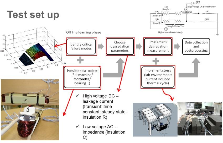
4 Degradation model and test verification Off line learning phase Identify critical failure modes Choose degradation parameters Impelement Implement degradation measurement Data collection and postprocessing Possible test object (full machine/ motorrete/ bearing...) Impelement Implement stress (lab environment: current induced thermal cycle) Build degradation model Usage of degradation model Load cycles Design EM with the required life span EM Degradation model On line data monitoring RUL Off line condition monitoring in workshop Detailed diagnostics + schedule spare part


5 Results
6 Conclusions Thermal and degradation model - Inputs: driving cycle, vhecile specifications, defined powertain - Outputs: temperature distribution while driving, expected lifetime - Design traction machine with required lifetime Accelerated lifetime test - Improved test method Stator segment VS single material Electrically heated winding and liquid cooling VS oven heating Thermal-mechanical model - Impregnation used to enhance the heat transfer induces mechanical stress to winding coating (primary insulation) under thermal stress improve the degradation model (thermal-mechanical stress VS insulation lifetime) Condition monitoring model - Global physical properties changes due to local insulation material aging improve the degradation model (usage time VS insulation quality) Prognostic measurement State of Health (SOH) - Povide quick health check of the traction motor before vehicle start daily - Simple hardware and software requirement (high frequency logging device needed)
7 Publications Zhe Huang, Francisco J. Marquez-Fernandez, Yury Loayza, Avo Reinap, and Mats Alaküla. "Dynamic thermal modeling and application of electrical machine in hybrid drives." International Conference on Electrical Machines (ICEM), pp IEEE, Zhe Huang, Avo Reinap, and M. Alaküla. "Predictive monitoring of turn-to-turn insulation in single tooth coils." 10th International Symposium on Diagnostics for Electrical Machines, Power Electronics and Drives (SDEMPED), IEEE, Zhe Huang, Avo Reinap, and M. Alaküla. Degradation and Fatigue of Epoxy Impregnated Traction Motors Due to Thermal and Thermal Induced Mechanical Stress Part I: Thermal Mechanical Simulation of Single Wire due to Evenly Distributed Temperature, 8 th International Conference on Power Electronics, Machines and Drives (PEMD), IET, Zhe Huang, Avo Reinap, and M. Alaküla. Degradation and Fatigue of Epoxy Impregnated Traction Motors Due to Thermal and Thermal Induced Mechanical Stress Part II: Thermal Mechanical Simulation of Multiple Wires due to Evenly and Unevenly Distributed Temperature, 8 th International Conference on Power Electronics, Machines and Drives (PEMD), IET, Zhe Huang, Avo Reinap, and M. Alaküla. Dielectric Properties Modeling and Measurement of Single Tooth Coil Insulation System under Accelerated Degradation Test, International Conference on Electrical Machines (ICEM), IEEE, 2016, full paper submitted
8 Thanks for your attention!
 Detailed Thermal Model (2) 9")
9 Thermal model Detailed Loss Model Mechanical Dynamics Model Detailed Thermal Model (1) Detailed Thermal Model (2)
![Life Time [hours] Lifetime model Degradation caused by thermal stress Life time versus constant thermal stress - L = Ae B/T - Hot spot temperature in](/docs-images/92/109682996/images/10-0.jpg "winding is the critical parameter for lifetime 10 5 10 4 10 3 Polyurethane TI155 Polyester TI180 Polyesterimide TI200 Polyester&Polyamide-imide TI220")
![10 2 150 200 250 300 Temp [ o C] Life time definition - Standard defines L50 - From L50 to Ln.](/docs-images/92/109682996/images/10-1.jpg ".. Cumulative distribution function shape factor β F t = 1 e t η β Temperature cycle counting algorithms - Mean edge (MIL Handbook) - RainFlow")
10 Life Time [hours] Lifetime model Degradation caused by thermal stress Life time versus constant thermal stress - L = Ae B/T - Hot spot temperature in winding is the critical parameter for lifetime Polyurethane TI155 Polyester TI180 Polyesterimide TI200 Polyester&Polyamide-imide TI Temp [ o C] Life time definition - Standard defines L50 - From L50 to Ln... Cumulative distribution function shape factor β F t = 1 e t η β Temperature cycle counting algorithms - Mean edge (MIL Handbook) - RainFlow (Fatigue estimation; consider the deepest cycle)
![Lifetime model results Diving Cycle US06 Thermal Index [ C] Life time by Mean edge [hours] Life time by](/docs-images/92/109682996/images/11-1.jpg "RainFlow [hours] 155 4 773 2 495 180 24 389 20 550 200 124 741 105 104 220 935 644 1 005 422 11")
11 Lifetime model results Diving Cycle US06 Thermal Index [ C] Life time by Mean edge [hours] Life time by RainFlow [hours]


 Impelement Implement stress (lab environment: current induced")
 Low voltage AC impedance")
12 Test set up 160 Off line learning phase Identify critical failure modes Choose degradation parameters Impelement Implement degradation measurement Data collection and postprocessing Possible test object (full machine/ motorette/ bearing...) Impelement Implement stress (lab environment: current induced thermal cycle) High voltage DC leakage current (transient: time constant; steady state: insulation R) Low voltage AC impedance (insulation C)


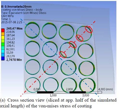

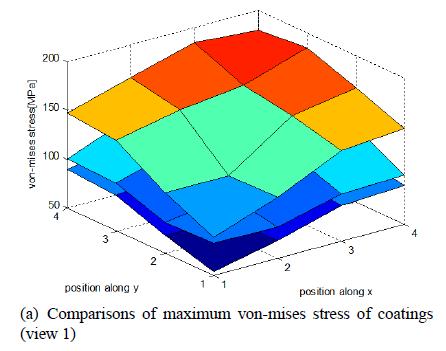
13 Improve model step 1 Thermalmechanical stress VS aging


 change")

14 Improve model step 2 Predictable properties change VS aging Single tooth winding under test Differnt winding configurations and fill factors Analytical modeling for condition monitoring Results Insulation resistance at different aging time of EM and coating thickness Results Insulation resistance developement during degradation: analytical modeling VS measurement Capacitance (phase to ground) change during degradation: measurement at different temperature cycle stresses FEA modeling for condition monitoring
 - Fault case: phase and ground failure Results - Method validation by lab equipment - Small influence by rotor position lock rotor - Up to 10 Mhz logging and")
15 Degradation model application Traction machine prognostics Theory - Traction machine on-line condition monitoring (State of Health) by parasitic capacitance changes with machine aging Meaurement set-up - On a PMSM (hybrid car traction) - Fault case: phase and ground failure Results - Method validation by lab equipment - Small influence by rotor position lock rotor - Up to 10 Mhz logging and current sensing requirement -> higher than control need but can be shared with battery diagnostic Current response with and without phase to ground fault, in time domain (left) and in frequency domain (right) PMSM under measurement