WAT-E Physical and Chemical Treatment of Water and Waste Filtration. Adjunct Prof. Riina Liikanen
|
|
|
- Wesley Hancock
- 5 years ago
- Views:
Transcription
1 WAT-E Physical and Chemical Treatment of Water and Waste Filtration Adjunct Prof. Riina Liikanen
2 Content / Learning outcomes Overview of granular media filtration Removal and transport mechanisms in granular media filtration Design and operating variables in granular media filtration Cleaning of filters After the lesson students should Know the principles of granular media filtration Understand the variables affecting granular media filtration Be able to calculate head loss in granular media filtration 2
3 Filtration Filtration processes primarily remove particulate, colloidal and susbended matter by passing water through a layer or bed of a porous material. Typical applications for removal of clay, silt, microbes, colloidal organic particulates and precipitates: after sedimentation/flocculation or direct filtration after flocculation to remove remaining flocs and fine particles (rapid filtration), as a polishing step for DW before final disinfection (slow sand filtration) as a tertiary WW treatment step before discharge 3
4 Classification of filters According to type of granular media used single medium (e.g. sand or anthracite ) dual media (e.g. anthracite and sand ) multi media (e.g. anthracite, sand, garnet) According to flow through medium Gravity filters are open to the atmosphere and flow through the medium is achieved by gravity In pressure filters filter media is contained in pressure vessel and water is delivered to the vessel under pressure 4
5 Gravity-driven granular media filter Rapid granular media filtration is the most common application in water treatment. Two modes of operation Filtration Backwash 5


6 Pressure filter 18/03/2017 6

7 Slow sand filtration 7

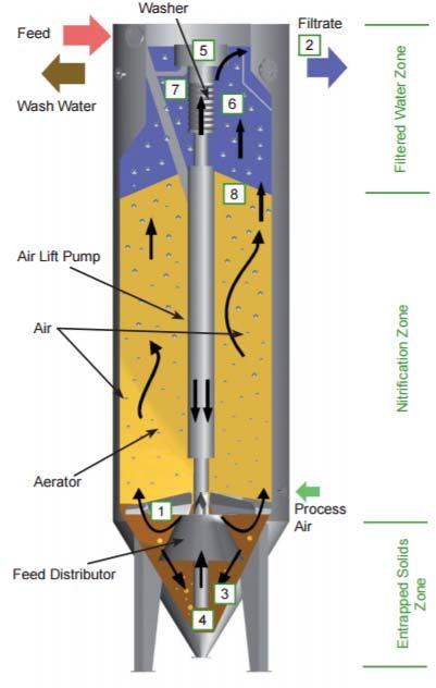
8 Disc filter and continuous sand filter 8
9 Filter Media Properties Size (effective size) Affects removal efficiency and headloss Size distribution (uniformity) Affects utilisation of bed capacity and media stratification Density Affects backwash flow velocity Shape (sphericity) Affects removal efficiency, headloss, backwash flow velocity, fixed bed porosity Porosity (fixed bed and loose bed) Depth Surface chemistry 9
10 Filter media properties Effective size of the filter media d 10 The effective size of the media is the diameter that 10% of the filter media is less than it size. Uniformity coefficient of the filter media d 60 /d 10 d 60 = sieve size that passes 60% by weight d 10 = sieve size that passes 10% by weight Another important sieve size is d 90 that is used to calculate the backwash velocity. d 10 d 60 and d 90 are found by sieve analysis of the media to be used in the filter. 10
11 Removal Mechanisms in Filtration The transport brings small particles from the bulk solution to the surface of the media by gravitational settling, diffusion, interception and hydrodynamics. At the surface of the filter media, an attachment mechanism is required to retain the particles electrostatic interactions chemical bridging adsorption destabilisation of influent particles affects the attachment 11
12 Mechanism of Filtration Transport is affected by physical characteristics such as size of the filter medium, filtration rate, fluid temperature, size and density of suspended solids. Water Quality Engineering: Physical / Chemical Treatment Processes, Chapter 14 12
13 Main Removal Mechanisms in Filtration Straining at the surface Sedimentation Interception Cake formation Adhesion and adsorption to the grains Microbial activity Rapid sand filtration x x x Slow sand filtration x x x 13

14 Gravity-driven granular media filter Operational monitoring Water level Effluent flow Time between backflushing Filtrate turbidity Water Quality Engineering: Physical / Chemical Treatment Processes, Chapter 14 14
15 Head loss = the difference between the pressure heads under static and flow conditions at this depth = energy expended per unit volume of water to pass the water through the filter In a filter with no flow (static conditions), the pressure head increases linearly with depth. If the clean media bed has uniform characteristics, the change in pressure head through the clean bed is linear, but the slope is less than above the bed, because energy is expended to overcome the friction between the water and the grains. Captured particles increase the head loss because they provide additional surface and therefore increase the frictional resistance to water flow and because they reduce the available pore volume for the flow. Water Quality Engineering: Physical / Chemical Treatment Processes, Chapter 14 15
16 Calculation of headloss, h L The Carman Kozeny equation is the fundamental equation describing the head loss in a clean filter bed as a function of properties of the fluid, properties of the media, and design and operating variables. where Z full length of the bed k empirical constant, generally 5 viscosity of water porosity L g S 0 v density of water gravitational constant surface area per unit volume of bed = shape factor/grain diameter superficial velocity, filtration rate = flow rate onto filter surface / surface area of filter Water Quality Engineering: Physical / Chemical Treatment Processes, Chapter 14 16
17 Example 1, Headloss calculation Calculate the headloss for a dual media filter composed of 0,3 m anthracite (mean size of 1,5 mm) above a 0,6 m layer of sand (mean size of 0,5 mm) at a filtration rate of 10 m/h and a water temperature of 15 o C. Assume shape factor of 7,5 and a porosity of 0,40 for both media. 17
18 Example 1, Head loss calculation Calculate the head loss for a dual media filter composed of 0,3 m anthracite (mean size of 1,5 mm) above a 0,6 m layer of sand (mean size of 0,5 mm) at a filtration rate of 10 m/h and a water temperature of 15 o C. Assume shape factor of 7,5 and a porosity of 0,40 for both media. Calculate the head loss separately for both media and sum up. k = 5 = 11,38 * 10-3 cm 2 /s = 0,40 L = 0,999 g/cm 3 g = 981 cm/s 2 S 0 = 0,75/0,15 cm; 0,75/0,06 cm v = 0,28 cm/s Z = 30 cm; 60 cm 18
19 Homework 1 19
20 Filter run / filter performance effluent quality and head loss Breakthrough Head loss should increase slowly enough that the filter can operate until a high normalized production is achieved Effluent should be of sufficient quality in the early part of a run that little or no water needs to be wasted or recycled before meeting the effluent guidelines. Effluent should meet water quality guidelines over a long time period. The head loss criterion should be met sooner than the water quality criterion. B = Backwashing necessary Water Quality Engineering: Physical / Chemical Treatment Processes, Chapter 14 20
21 Effects of Operating Variables on Length of Filter Run depth, increased collection less friction, reduced collection velocity, more particles enter, reduced collection, higher breakoff Water Quality Engineering: Physical / Chemical Treatment Processes, Chapter 14 21
22 Example 2, operating variables The locations of the two lines depend on all the other design and operational variables as well as on the values set for the two criteria. Show how the two lines would move on different variables. Water Quality Engineering: Physical / Chemical Treatment Processes, Chapter 14 22
23 Example 2: Reduce the maximum allowable head loss. Water Quality Engineering: Physical / Chemical Treatment Processes, Chapter 14 23
24 Example 2: Reduce the maximum allowable effluent concentration Water Quality Engineering: Physical / Chemical Treatment Processes, Chapter 14 24
25 Example 2: Reduce the depth of the media Water Quality Engineering: Physical / Chemical Treatment Processes, Chapter 14 25
26 Example 2: Reduce the filtration velocity (volume throughput as the ordinate) Water Quality Engineering: Physical / Chemical Treatment Processes, Chapter 14 26
27 Example 2: Reduce the influent concentration Water Quality Engineering: Physical / Chemical Treatment Processes, Chapter 14 27
28 Example 2: Reduce the depth of the media Water Quality Engineering: Physical / Chemical Treatment Processes, Chapter 14 28
29 Homework 2 29
30 Filter cleaning Need for backwash is indicated by one of the following criteria: Increase of head loss across the filter to the available limit or to a lower established limit Deterioration of filtered water quality Maximum time limit Water Quality Engineering: Physical / Chemical Treatment Processes, Chapter 14 30
31 Backwashing During backwashing the net downward force (gravity minus buoyancy) on the media is balanced by the upward drag force exerted by the moving fluid on a velocity by which, the packed media is fluidized (the filter grains no longer be supported by each other but by the force of the rising fluid). At velocities above the minimum required for fluidization (v mf ), the bed expands. Media washout should be avoided. The v mf is a function of the porosity of the bed, the diameter and density of the grains, and the temperature. It is easily evaluated numerically for a specific situation using the d 90 size of grains. Backwashing is often insufficient to clean the media by itself. Water Quality Engineering: Physical / Chemical Treatment Processes, Chapter 14 31
32 Surface wash To break up the cake on top of the filter, a high-velocity downward water flow is injected before the start of the vertically upward flow of the backwash. Surface wash systems only affect the top several centimeters of the bed most effective for monomedia filters with relatively small media size 32
33 Air scour Air is supplied in a separate system from the backwash flow, through nozzles at the bottom of the media. The goal is to have the bubbles form, collapse, and reform a number of times as they rise; this condition has been called collapse-pulsing. Backwashing is most effective in systems with air scour if the water velocity is considerably below that required for fluidization of the bed. 33