If you have any further questions, feel free to contact me at or by at
|
|
|
- Rolf Williams
- 5 years ago
- Views:
Transcription

1 July 20, 2017 City of Thornton Colorado City Development Engineering 9500 Civic Circle Drive Thornton, CO Subject: Panda Express, Thornton, CO 144 th and Washington Summit, Lot 1 and Lot 2a Stormwater Compliance The proposed Panda Express and additional drive thru restaurant identified at the above referenced site do not exceed the development s Final Drainage Report assumed design impervious area. Therefore, additional detention and water quality facilities are not required. The study, prepared by Jansen Strawn Consulting Engineers (dated April 29, 2016), assumes an 85% impervious area (75,922 sq. ft.) for the two lots. The proposed development is 78% impervious (68,955 sq. ft.). The proposed development produces a cumulative peak runoff of cfs in the 100-year design storm (RE: 100-year drainage calculation table). The system ties into the developer s stormwater infrastructure at an 18 RCP on the property this pipe is at 2.49% slope, giving it a capacity of cfs. In the assumed condition (85% impervious) the peak runoff would be cfs. Pre-construction and post-construction drainage maps, UD-inlet design spreadsheets, the UDrational method spreadsheet, and storm sewer conveyance calculations are attached. If you have any further questions, feel free to contact me at or by at mark.johnson@ibhc.com Sincerely, Mark S. Johnson, P.E. Vice President, Development Services BHC Rhodes 7101 College Blvd, Suite 400 Overland Park, KS BHC RHODES is a Trademark of Brungardt Honomichl & Company, P.A College Blvd., Suite 400 Overland Park, KS P: (913) ibhc.com
2 " hereby certifies that the drainage facilities for will be constructed according to the design presented in this report. I understand that the City of Thornton does not and shall not assume liability for the drainage facilities designed and/or certified by my engineer. I understand that the City of Thornton reviews drainage plans but cannot, on behalf of, guarantee that final drainage design review will absolve and/or their successors and/or assigns of future liability for improper design. I further understand that approval of the Plat and/or Development Permit does not imply approval of my engineer's drainage design." Attest: Name of Responsible Party Notary Public Authorized Signature "I hereby certify that this report (plan) for the final drainage design of (Name of Development) was prepared by me (or under my direct supervision) in accordance with the provisions of the City of Thornton Standards and Specifications for the Design and Construction of Public and Private Improvements for the Responsible Parties thereof. I understand that the City of Thornton does not and shall not assume liability for drainage facilities designed by others." Mark S. Johnson Registered Professional Engineer State of Colorado No. PE
3 O UGE UGE O UGC UGC UGC UGC UGC UGC UGC UGC UGC UGC UGC UGE UGE UGE UGE UGE X AC c= TH AVE AND WASHINGTON ST COMMERCIAL CONCEPTUAL SITE PLAN AMENDMENT UGE UGE UGE UGE UGE UGE X AC c=0.30 THORNTON, COLORADO UGE X1 UGE UGE (No Posted Address) Lot 3A of 144th and Washington Filing No. 1 Amendment No. 1 Owner: Summit Entertainment of Thornton LLC Case No.: PLCSPA GENERAL DRAINAGE NOTES 1. STORM DRAINAGE SHALL NOT ENTER ANY EXISTING IRRIGATION CHANNELS. THE DEVELOPER WILL BE RESPONSIBLE R BYPASSING THESE FACILITIES AS REQUIRED BY THE CITY AND THE APPROPRIATE DITCH COMPANY. 2. ALL OFF-SITE EASEMENTS REQUIRED TO CONVEY DEVELOPED DRAINAGE TO AN ACCEPTABLE OUTFALL LOCATION, AS DETERMINED BY THE CITY, SHALL BE ACQUIRED AND RECORDED BY THE DEVELOPER PRIOR TO APPROVAL OF THE SUBDIVISION PLAT. THE RECEPTION NUMBER(S) R THESE EASEMENTS SHALL BE SHOWN ON THE PLAT. 3. INFRASTRUCTURE SHALL BE PROVIDED TO ALLOW ALL UPSTREAM PARCELS WHO HISTORICALLY CONVEY DRAINAGE THROUGH THE DEVELOPMENT. 4. SEEPAGE ANALYSIS AND STRUCTURAL BANK INTEGRITY ANALYSIS R EACH EXISTING (IF IT IS UPSTREAM) AND EACH DRAINAGEWAY WITHIN THE DEVELOPMENT SHALL BE SUBMITTED TO THE CITY WITH THE FIRST SUBDIVISION PLAT R THE PROPERTY. 5. A NOTE SHALL BE ADDED TO INDICATED HOW NUISANCE FLOWS WILL BE HANDLED THROUGH PARCELS DOWNSTREAM OF THE DEVELOPMENT AND IF ANY EASEMENTS ARE ANTICIPATED TO BE ACQUIRED BY THE DEVELOPER. THIS MAY INCLUDE LETTERS OF ACKNOWLEDGEMENT FROM THE DOWNSTREAM PROPERTY OWNER(S) BETWEEN THE PROPOSED DEVELOPMENT AND AN APPROVED DRAINAGEWAY. 6. THE IMPROVES SHALL CONRM TO THE CURRENT DRAINAGE MASTER PLAN AT THE TIME OF DEVELOPMENT. IF THERE IS NOT A MASTER PLAN AT THE TIME OF DEVELOPMENT, THE DEVELOPER WILL BE REQUIRED TO PREPARE A BASIN STUDY TO DETERMINE THE IMPACTS AND IDENTIFY MITIGATION MEASURE R THE PROPOSED PROJECT. APPROVAL IS REQUIRED FROM URBAN DRAINAGE AND FLOOD CONTROL DISTRICT (UCFD) R THESE IMPROVEMENTS. STORM WATER QUALITY AND DETENTION ARE REQUIRED R ALL PORTIONS OF THE DEVELOPMENT INCLUDING THE ULTIMATE ROADWAY CONSTRUCTION. 7. CLOMR'S/LOMR'S WILL BE REQUIRED WITH THIS DEVELOPMENT R ANY ADJUSTMENTS TO THE FLOODPLAIN. 8. ALL WETLANDS AND BODIES OF WATER SHALL BE IDENTIFIED ON THE DRAINAGE PLAN. NO LOTS SHALL BE WITHIN A 50 OT RADIUS OF A DELINEATED WETLANDS AND 75 OT RADIUS OF ANY BODY OF WATER. 9. DETENTION BONDS SHALL BE COMBINED WHEREVER POSSIBLE AND SHALL BE SIZED USING CUHP OR AN EQUIVALENT INFLOW HYDROGRAPH METHOD. 10. ACCESS SHALL BE PROVIDED TO ALL DRAINAGEWAYS AND DETENTION PONDS R MAINTENANCE. 11. CONTOURS AND STORM SEWER INFRASTRUCTURE SHOWN PROVIDED BY JANSEN STRAWN CONSULTING ENGINEERS ON MARCH 15, CONTRACTOR TO FIELD VERIFY EXISTING CONDITIONS. LEGEND LC 2017 p r o cft j et ci tt l, s t n pme o l e v De H.C. KLOVER ARCHITECT LOWELL AVENUE, SUITE 700 OVERLAND PARK, KS ph: fx: E 144th Ave & Grant Thornton, CO UGC W W W W W W W W W W W W W W W W p r o j e cn tu m b e r d r a w i in sgs u a n c UGC x OFF WW? d r a w i rnegv i s i o No. Description: MM.DD.YY Date: x (No Posted Address) Lot 1 of Block 1 of Washington Electric Substation Filing No. 1 Owner: Public Service Company of Colorado p r o f e s s i os en a l O C M L O R A DO ARK S. L I C E N JOHNSON SE D PE P R R O F E S S I O N AL N E E E NGI 7101 College Blvd., Suite 400 Overland Park, Kansas p. (913) f. (913) BHC RHODES is a trademark of Brungardt Honomichl & Company, P.A. d r a w i n gt i t l e EXIST. DRAINA d r a w i nn gu m b e r C400


4 UGC UGC UGE GAS UGE 4. GAS GAS 2. UGE 3. UGC UGC UGC GAS 5. GAS UGC UGC UGC UGC GAS UGC S AC c= S AC c= SA N UG SA N UGC E GAS S AC c=0.90 S AC c= S AC c= UGC UGC UGC UGC SAN W S AC c=0.86 STORM DRAINAGE SHALL NOT ENTER ANY EXISTING IRRIGATION CHANNELS. THE DEVELOPER WILL BE RESPONSIBLE R BYPASSING THESE FACILITIES AS REQUIRED BY THE CITY AND THE APPROPRIATE DITCH COMPANY. ALL OFF-SITE EASEMENTS REQUIRED TO CONVEY DEVELOPED DRAINAGE TO AN ACCEPTABLE OUTFALL LOCATION, AS DETERMINED BY THE CITY, SHALL BE ACQUIRED AND RECORDED BY THE DEVELOPER PRIOR TO APPROVAL OF THE SUBDIVISION PLAT. THE RECEPTION NUMBER(S) R THESE EASEMENTS SHALL BE SHOWN ON THE PLAT. INFRASTRUCTURE SHALL BE PROVIDED TO ALLOW ALL UPSTREAM PARCELS WHO HISTORICALLY CONVEY DRAINAGE THROUGH THE DEVELOPMENT. SEEPAGE ANALYSIS AND STRUCTURAL BANK INTEGRITY ANALYSIS R EACH EXISTING (IF IT IS UPSTREAM) AND EACH DRAINAGEWAY WITHIN THE DEVELOPMENT SHALL BE SUBMITTED TO THE CITY WITH THE FIRST SUBDIVISION PLAT R THE PROPERTY. A NOTE SHALL BE ADDED TO INDICATED HOW NUISANCE FLOWS WILL BE HANDLED THROUGH PARCELS DOWNSTREAM OF THE DEVELOPMENT AND IF ANY EASEMENTS ARE ANTICIPATED TO BE ACQUIRED BY THE DEVELOPER. THIS MAY INCLUDE LETTERS OF ACKNOWLEDGEMENT FROM THE DOWNSTREAM PROPERTY OWNER(S) BETWEEN THE PROPOSED DEVELOPMENT AND AN APPROVED DRAINAGEWAY. THE IMPROVES SHALL CONRM TO THE CURRENT DRAINAGE MASTER PLAN AT THE TIME OF DEVELOPMENT. IF THERE IS NOT A MASTER PLAN AT THE TIME OF DEVELOPMENT, THE DEVELOPER WILL BE REQUIRED TO PREPARE A BASIN STUDY TO DETERMINE THE IMPACTS AND IDENTIFY MITIGATION MEASURE R THE PROPOSED PROJECT. APPROVAL IS REQUIRED FROM URBAN DRAINAGE AND FLOOD CONTROL DISTRICT (UCFD) R THESE IMPROVEMENTS. STORM WATER QUALITY AND DETENTION ARE REQUIRED R ALL PORTIONS OF THE DEVELOPMENT INCLUDING THE ULTIMATE ROADWAY CONSTRUCTION. CLOMR'S/LOMR'S WILL BE REQUIRED WITH THIS DEVELOPMENT R ANY ADJUSTMENTS TO THE FLOODPLAIN. ALL WETLANDS AND BODIES OF WATER SHALL BE IDENTIFIED ON THE DRAINAGE 2017 H.C. KLOVER ARCHITECT PLAN. NO LOTS SHALL BE WITHIN A 50 OT RADIUS OF A DELINEATED WETLANDS AND 75 OT RADIUS OF ANY BODY OF WATER. DETENTION BONDS SHALL BE COMBINED WHEREVER POSSIBLE AND SHALL BE SIZED USING CUHP OR AN EQUIVALENT INFLOW HYDROGRAPH METHOD. ACCESS SHALL BE PROVIDED TO ALL DRAINAGEWAYS AND DETENTION PONDS R MAINTENANCE. GRADING SHOWN ON THIS PLAN IS CONCEPTUAL ONLY. FINALIZED GRADING PLAN WILL BE INCLUDED IN CONSTRUCTION DOCUMENTS. 201 UGE LEGEND W UGE project title W c ft SA N UGC W NVDevelopments,LLC N W SA 202 W W W W W W W W W W W W W W OFF W UGC CFT W W 101 NV DEVELOPMENTS, LLC SAN W W UGC W S AC c= Ridge Road Parma, OH UGC LOWELL AVENUE, SUITE 700 OVERLAND PARK, KS ph: fx: UGC GAS UGE GAS UGE UGE GAS UG C U GC UGC S AC c=0.73 UGC 102 UGC UGE UGE UGE S AC c=0.55 UGC 103 Based on grading, this area is in S6 1. UGE UGE UGE UGE UGE UGE UGE GENERAL DRAINAGE NOTES UGE UGE UGE UGE Case No.: PLCSPA x W x project number drawing issuance BID xx.xx.2017 drawing No. This table doesn't match Rational Method table on page 13 revisions Description: professional drawing Date: seal title PROP. DRAINAGE drawing number C401
5 Project: Inlet ID: Version 4.05 Released March 2017 ALLOWABLE CAPACITY R ONE-HALF OF STREET (Minor & Major Storm) (Based on Regulated Criteria for Maximum Allowable Flow Depth and Spread) Enter Your Project Name Here 103 Gutter Geometry (Enter data in the blue cells) Maximum Allowable Width for Spread Behind Curb T BACK = 6.0 ft Side Slope Behind Curb (leave blank for no conveyance credit behind curb) S BACK = ft/ft Manning's Roughness Behind Curb (typically between and 0.020) n BACK = Height of Curb at Gutter Flow Line H CURB = 6.00 inches Distance from Curb Face to Street Crown T CROWN = 14.0 ft Gutter Width W = 1.50 ft Street Transverse Slope S X = ft/ft Gutter Cross Slope (typically 2 inches over 24 inches or ft/ft) S W = ft/ft Street Longitudinal Slope - Enter 0 for sump condition S O = ft/ft Manning's Roughness for Street Section (typically between and 0.020) n STREET = Minor Storm Major Storm Max. Allowable Spread for Minor & Major Storm T MAX = ft Max. Allowable Depth at Gutter Flowline for Minor & Major Storm d MAX = inches Check boxes are not applicable in SUMP conditions MINOR STORM Allowable Capacity is based on Depth Criterion Minor Storm Major Storm MAJOR STORM Allowable Capacity is based on Depth Criterion Q allow = SUMP SUMP cfs UD-Inlet_v4.05.xlsm, 103 7/20/2017, 9:33 AM
6 INLET IN A SUMP OR SAG LOCATION Version 4.05 Released March 2017 H-Curb W W P H-Vert Lo (C) Wo Lo (G) Design Information (Input) MINOR MAJOR CDOT Type R Curb Opening Type of Inlet Type = CDOT Type R Curb Opening Local Depression (additional to continuous gutter depression 'a' from above) a local = inches Number of Unit Inlets (Grate or Curb Opening) No = 1 1 Water Depth at Flowline (outside of local depression) Ponding Depth = inches Grate Information MINOR MAJOR Override Depths Length of a Unit Grate L o (G) = N/A N/A feet Width of a Unit Grate W o = N/A N/A feet Area Opening Ratio for a Grate (typical values ) A ratio = N/A N/A Clogging Factor for a Single Grate (typical value ) C f (G) = N/A N/A Grate Weir Coefficient (typical value ) C w (G) = N/A N/A Grate Orifice Coefficient (typical value ) C o (G) = N/A N/A Curb Opening Information MINOR MAJOR Length of a Unit Curb Opening L o (C) = feet Height of Vertical Curb Opening in Inches H vert = inches Height of Curb Orifice Throat in Inches H throat = inches Angle of Throat (see USDCM Figure ST-5) Theta = degrees Side Width for Depression Pan (typically the gutter width of 2 feet) W p = feet Clogging Factor for a Single Curb Opening (typical value 0.10) C f (C) = Curb Opening Weir Coefficient (typical value ) C w (C) = Curb Opening Orifice Coefficient (typical value ) C o (C) = Low Head Performance Reduction (Calculated) MINOR MAJOR Depth for Grate Midwidth d Grate = N/A N/A ft Depth for Curb Opening Weir Equation d Curb = ft Combination Inlet Performance Reduction Factor for Long Inlets RF Combination = Curb Opening Performance Reduction Factor for Long Inlets RF Curb = Grated Inlet Performance Reduction Factor for Long Inlets RF Grate = N/A N/A MINOR MAJOR Total Inlet Interception Capacity (assumes clogged condition) Q a = cfs Inlet Capacity IS GOOD for Minor and Major Storms(>Q PEAK) Q PEAK REQUIRED = cfs UD-Inlet_v4.05.xlsm, 103 7/20/2017, 9:33 AM
7 Project: Inlet ID: Version 4.05 Released March 2017 ALLOWABLE CAPACITY R ONE-HALF OF STREET (Minor & Major Storm) (Based on Regulated Criteria for Maximum Allowable Flow Depth and Spread) Enter Your Project Name Here 102 Gutter Geometry (Enter data in the blue cells) Maximum Allowable Width for Spread Behind Curb T BACK = 6.0 ft Side Slope Behind Curb (leave blank for no conveyance credit behind curb) S BACK = ft/ft Manning's Roughness Behind Curb (typically between and 0.020) n BACK = Height of Curb at Gutter Flow Line H CURB = 6.00 inches Distance from Curb Face to Street Crown T CROWN = 20.0 ft Gutter Width W = 1.50 ft Street Transverse Slope S X = ft/ft Gutter Cross Slope (typically 2 inches over 24 inches or ft/ft) S W = ft/ft Street Longitudinal Slope - Enter 0 for sump condition S O = ft/ft Manning's Roughness for Street Section (typically between and 0.020) n STREET = Minor Storm Major Storm Max. Allowable Spread for Minor & Major Storm T MAX = ft Max. Allowable Depth at Gutter Flowline for Minor & Major Storm d MAX = inches Check boxes are not applicable in SUMP conditions MINOR STORM Allowable Capacity is based on Depth Criterion Minor Storm Major Storm MAJOR STORM Allowable Capacity is based on Depth Criterion Q allow = SUMP SUMP cfs UD-Inlet_v4.05.xlsm, 102 7/20/2017, 9:33 AM
8 INLET IN A SUMP OR SAG LOCATION Version 4.05 Released March 2017 H-Curb W W P H-Vert Lo (C) Wo Lo (G) Design Information (Input) MINOR MAJOR CDOT Type R Curb Opening Type of Inlet Type = CDOT Type R Curb Opening Local Depression (additional to continuous gutter depression 'a' from above) a local = inches Number of Unit Inlets (Grate or Curb Opening) No = 1 1 Water Depth at Flowline (outside of local depression) Ponding Depth = inches Grate Information MINOR MAJOR Override Depths Length of a Unit Grate L o (G) = N/A N/A feet Width of a Unit Grate W o = N/A N/A feet Area Opening Ratio for a Grate (typical values ) A ratio = N/A N/A Clogging Factor for a Single Grate (typical value ) C f (G) = N/A N/A Grate Weir Coefficient (typical value ) C w (G) = N/A N/A Grate Orifice Coefficient (typical value ) C o (G) = N/A N/A Curb Opening Information MINOR MAJOR Length of a Unit Curb Opening L o (C) = feet Height of Vertical Curb Opening in Inches H vert = inches Height of Curb Orifice Throat in Inches H throat = inches Angle of Throat (see USDCM Figure ST-5) Theta = degrees Side Width for Depression Pan (typically the gutter width of 2 feet) W p = feet Clogging Factor for a Single Curb Opening (typical value 0.10) C f (C) = Curb Opening Weir Coefficient (typical value ) C w (C) = Curb Opening Orifice Coefficient (typical value ) C o (C) = Low Head Performance Reduction (Calculated) MINOR MAJOR Depth for Grate Midwidth d Grate = N/A N/A ft Depth for Curb Opening Weir Equation d Curb = ft Combination Inlet Performance Reduction Factor for Long Inlets RF Combination = Curb Opening Performance Reduction Factor for Long Inlets RF Curb = Grated Inlet Performance Reduction Factor for Long Inlets RF Grate = N/A N/A MINOR MAJOR Total Inlet Interception Capacity (assumes clogged condition) Q a = cfs Inlet Capacity IS GOOD for Minor and Major Storms(>Q PEAK) Q PEAK REQUIRED = cfs UD-Inlet_v4.05.xlsm, 102 7/20/2017, 9:33 AM
9 Project: Inlet ID: Version 4.05 Released March 2017 ALLOWABLE CAPACITY R ONE-HALF OF STREET (Minor & Major Storm) (Based on Regulated Criteria for Maximum Allowable Flow Depth and Spread) Enter Your Project Name Here 202 Gutter Geometry (Enter data in the blue cells) Maximum Allowable Width for Spread Behind Curb T BACK = 6.0 ft Side Slope Behind Curb (leave blank for no conveyance credit behind curb) S BACK = ft/ft Manning's Roughness Behind Curb (typically between and 0.020) n BACK = Height of Curb at Gutter Flow Line H CURB = 6.00 inches Distance from Curb Face to Street Crown T CROWN = 30.0 ft Gutter Width W = 1.50 ft Street Transverse Slope S X = ft/ft Gutter Cross Slope (typically 2 inches over 24 inches or ft/ft) S W = ft/ft Street Longitudinal Slope - Enter 0 for sump condition S O = ft/ft Manning's Roughness for Street Section (typically between and 0.020) n STREET = Minor Storm Major Storm Max. Allowable Spread for Minor & Major Storm T MAX = ft Max. Allowable Depth at Gutter Flowline for Minor & Major Storm d MAX = inches Check boxes are not applicable in SUMP conditions MINOR STORM Allowable Capacity is based on Depth Criterion Minor Storm Major Storm MAJOR STORM Allowable Capacity is based on Depth Criterion Q allow = SUMP SUMP cfs UD-Inlet_v4.05.xlsm, 202 7/20/2017, 9:33 AM
10 INLET IN A SUMP OR SAG LOCATION Version 4.05 Released March 2017 H-Curb W W P H-Vert Lo (C) Wo Lo (G) Design Information (Input) MINOR MAJOR CDOT Type R Curb Opening Type of Inlet Type = CDOT Type R Curb Opening Local Depression (additional to continuous gutter depression 'a' from above) a local = inches Number of Unit Inlets (Grate or Curb Opening) No = 1 1 Water Depth at Flowline (outside of local depression) Ponding Depth = inches Grate Information MINOR MAJOR Override Depths Length of a Unit Grate L o (G) = N/A N/A feet Width of a Unit Grate W o = N/A N/A feet Area Opening Ratio for a Grate (typical values ) A ratio = N/A N/A Clogging Factor for a Single Grate (typical value ) C f (G) = N/A N/A Grate Weir Coefficient (typical value ) C w (G) = N/A N/A Grate Orifice Coefficient (typical value ) C o (G) = N/A N/A Curb Opening Information MINOR MAJOR Length of a Unit Curb Opening L o (C) = feet Height of Vertical Curb Opening in Inches H vert = inches Height of Curb Orifice Throat in Inches H throat = inches Angle of Throat (see USDCM Figure ST-5) Theta = degrees Side Width for Depression Pan (typically the gutter width of 2 feet) W p = feet Clogging Factor for a Single Curb Opening (typical value 0.10) C f (C) = Curb Opening Weir Coefficient (typical value ) C w (C) = Curb Opening Orifice Coefficient (typical value ) C o (C) = Low Head Performance Reduction (Calculated) MINOR MAJOR Depth for Grate Midwidth d Grate = N/A N/A ft Depth for Curb Opening Weir Equation d Curb = ft Combination Inlet Performance Reduction Factor for Long Inlets RF Combination = Curb Opening Performance Reduction Factor for Long Inlets RF Curb = Grated Inlet Performance Reduction Factor for Long Inlets RF Grate = N/A N/A MINOR MAJOR Total Inlet Interception Capacity (assumes clogged condition) Q a = cfs Inlet Capacity IS GOOD for Minor and Major Storms(>Q PEAK) Q PEAK REQUIRED = cfs UD-Inlet_v4.05.xlsm, 202 7/20/2017, 9:33 AM
11 Project: Inlet ID: Version 4.05 Released March 2017 ALLOWABLE CAPACITY R ONE-HALF OF STREET (Minor & Major Storm) (Based on Regulated Criteria for Maximum Allowable Flow Depth and Spread) Enter Your Project Name Here 201 Gutter Geometry (Enter data in the blue cells) Maximum Allowable Width for Spread Behind Curb T BACK = 6.0 ft Side Slope Behind Curb (leave blank for no conveyance credit behind curb) S BACK = ft/ft Manning's Roughness Behind Curb (typically between and 0.020) n BACK = Height of Curb at Gutter Flow Line H CURB = 6.00 inches Distance from Curb Face to Street Crown T CROWN = 30.0 ft Gutter Width W = 1.50 ft Street Transverse Slope S X = ft/ft Gutter Cross Slope (typically 2 inches over 24 inches or ft/ft) S W = ft/ft Street Longitudinal Slope - Enter 0 for sump condition S O = ft/ft Manning's Roughness for Street Section (typically between and 0.020) n STREET = Minor Storm Major Storm Max. Allowable Spread for Minor & Major Storm T MAX = ft Max. Allowable Depth at Gutter Flowline for Minor & Major Storm d MAX = inches Check boxes are not applicable in SUMP conditions MINOR STORM Allowable Capacity is based on Depth Criterion Minor Storm Major Storm MAJOR STORM Allowable Capacity is based on Depth Criterion Q allow = SUMP SUMP cfs UD-Inlet_v4.05.xlsm, 201 7/20/2017, 9:33 AM
12 INLET IN A SUMP OR SAG LOCATION Version 4.05 Released March 2017 H-Curb W W P H-Vert Lo (C) Wo Lo (G) Design Information (Input) MINOR MAJOR CDOT Type R Curb Opening Type of Inlet Type = CDOT Type R Curb Opening Local Depression (additional to continuous gutter depression 'a' from above) a local = inches Number of Unit Inlets (Grate or Curb Opening) No = 1 1 Water Depth at Flowline (outside of local depression) Ponding Depth = inches Grate Information MINOR MAJOR Override Depths Length of a Unit Grate L o (G) = N/A N/A feet Width of a Unit Grate W o = N/A N/A feet Area Opening Ratio for a Grate (typical values ) A ratio = N/A N/A Clogging Factor for a Single Grate (typical value ) C f (G) = N/A N/A Grate Weir Coefficient (typical value ) C w (G) = N/A N/A Grate Orifice Coefficient (typical value ) C o (G) = N/A N/A Curb Opening Information MINOR MAJOR Length of a Unit Curb Opening L o (C) = feet Height of Vertical Curb Opening in Inches H vert = inches Height of Curb Orifice Throat in Inches H throat = inches Angle of Throat (see USDCM Figure ST-5) Theta = degrees Side Width for Depression Pan (typically the gutter width of 2 feet) W p = feet Clogging Factor for a Single Curb Opening (typical value 0.10) C f (C) = Curb Opening Weir Coefficient (typical value ) C w (C) = Curb Opening Orifice Coefficient (typical value ) C o (C) = Low Head Performance Reduction (Calculated) MINOR MAJOR Depth for Grate Midwidth d Grate = N/A N/A ft Depth for Curb Opening Weir Equation d Curb = ft Combination Inlet Performance Reduction Factor for Long Inlets RF Combination = Curb Opening Performance Reduction Factor for Long Inlets RF Curb = Grated Inlet Performance Reduction Factor for Long Inlets RF Grate = N/A N/A MINOR MAJOR Total Inlet Interception Capacity (assumes clogged condition) Q a = cfs Inlet Capacity IS GOOD for Minor and Major Storms(>Q PEAK) Q PEAK REQUIRED = cfs UD-Inlet_v4.05.xlsm, 201 7/20/2017, 9:33 AM
13 Designer: MIS Version 2.00 released May 2017 Select UDFCD location for NOAA Atlas 14 Rainfall Depths from the pulldown list OR enter your own depths obtained from the NOAA website (click this link) Company: BHC Rhodes t 2-yr 5-yr 10-yr 25-yr 50-yr 100-yr 500-yr C L t Computed t. t t 5 (urban) Date: 7/20/2017 Cells of this color are for required user-input S t 10 (non urban) 1-hour rainfall depth, P1 (in) = Project: Panda Express Cells of this color are for optional override values a b c Location: 144th and Washinton Cells of this color are for calculated results based on overrides Rainfall Intensity Equation Coefficients = I / a P t L L L Regional t b t 60K S 60V 26 17i Selected t 60 14i 9 S max t, min Computed t, Regional t Q CIA Subcatchment Name Area (ac) NRCS Hydrologic Soil Group Percent Imperviousness Runoff Coefficient, C 2-yr 5-yr 10-yr 25-yr 50-yr 100-yr 500-yr Overland U/S Elevation Flow Length (ft) L i (ft) (Optional) D/S Elevation (ft) (Optional) Overland Flow Slope S i (ft/ft) Overland Flow Time t i (min) Calculation of Peak Runoff using Rational Method Overland (Initial) Flow Time Channelized (Travel) Flow Time Time of Concentration Channelized U/S Elevation Flow Length (ft) L t (ft) (Optional) D/S Elevation (ft) (Optional) Channelized Flow Slope S t (ft/ft) NRCS Conveyance Factor K Channelized Flow Velocity V t (ft/sec) Channelized Flow Time t t (min) Computed t c (min) Regional t c (min) Selected t c (min) Rainfall Intensity, I (in/hr) 2-yr 5-yr 10-yr 25-yr 50-yr 100-yr 500-yr 2-yr 5-yr 10-yr 25-yr 50-yr 100-yr 500-yr S C S C S C S C S C S C S C S C S C Peak Flow, Q (cfs)
14 Project Name: Project #: Time: CFT - Thornton, CO /20/2017 9:44 Curb Type: City: Thornton, CO Design Storm: 5 "K" Value: 1.00 "F" Factor: 1.00 Runoff Calculations Pipe Properties Cumul. Runoff Up Up Up Drop Inlet Area "C" Area Cumul. To Cumul. Pipe Pipe Piped Piped Area Up Up Down Pipe "n" Pipe Slope In Inlet HGL # (acres) Value (acres) CxA Tc Intensity Inlet Runoff Cap. Vel. Inlets Inlets (acres) CxA Inlet Inlet Type Value Size Length % Inlet FL Up FL Down Top Elev. LINE 100 DS STR #EX1 FREE EX1 RCP HDPE HDPE HDPE HDPE N/A LINE 200 Drop in Inlet RCP RCP N/A
15 Project Name: Project #: Time: CFT - Thornton, CO /20/2017 9:44 Curb Type: City: Thornton, CO Design Storm: 100 "K" Value: 1.25 "F" Factor: 1.00 Runoff Calculations Pipe Properties Cumul. Runoff Up Up Up Drop Inlet Area "C" Area Cumul. To Cumul. Pipe Pipe Piped Piped Area Up Up Down Pipe "n" Pipe Slope In Inlet HGL # (acres) Value (acres) CxA Tc Intensity Inlet Runoff Cap. Vel. Inlets Inlets (acres) CxA Inlet Inlet Type Value Size Length % Inlet FL Up FL Down Top Elev. LINE 100 DS STR #EX1 FREE EX1 RCP HDPE HDPE HDPE HDPE N/A LINE 200 Drop in Inlet RCP RCP N/A


16 RELEASED Crystal Carlow Nate Hatleback R CONSTRUCTION City of Thornton Dev. Eng. 11/23/ /26/16 These plans were reviewed for compliance with City Codes, Engineer of record is responsible for adequacy of design and ensuring that improvements meet all City Codes
17
18 144 th and Washington Summit April 29, 2016 Page 3 T A B L E O F C O N T E N T S I. INTRODUCTION... 5 II. GENERAL LOCATION AND DESCRIPTION A. Location... 5 B. Description of Property III. DRAINAGE BASINS AND SUB-BASINS A. Major Basin Descriptions... 6 B. Sub-Basin Description... 7 IV. DRAINAGE DESIGN CRITERIA A. Regulations... 7 B. Development Criteria Reference and Constraints... 8 C. Hydrologic Criteria... 8 D. Hydraulic Criteria... 9 V. DRAINAGE FACILITY DESIGN A. General Concepts... 9 B. Specific Details Basins Full-Spectrum Detention VI. CONCLUSION VII. REFERENCES t f West 2 nd Avenue, Denver, Colorado
19 144 th and Washington Summit April 29, 2016 Page 4 A P P E N D I C E S APPENDIX A Vicinity Map NRCS Soil Information Effective FEMA Map Panels City of Thornton Rainfall APPENDIX B % Impervious Calculations C Value Calculations SF2 & SF3 Rational Method Calculations Inlet Calculations Storm Sewer Design Onsite Swale Design APPENDIX C Pond Calculations APPENDIX D Historic Basins Map Developed Basins Map t f West 2 nd Avenue, Denver, Colorado
20 144 th and Washington Summit April 29, 2016 Page 5 I. INTRODUCTION The purpose of this report is to define and analyze developed runoff quantities and conveyance through the 144 th and Washington Commercial development. Runoff from the developed portions of the property will generally drain towards the eastern edge of the subject property, where a full-spectrum detention pond has been designed to provide water quality and detention for the site in the ultimate developed condition. The proposed onsite pond will discharge to existing adjacent storm sewer within Washington Street rightof-way. Development constraints from the existing condition and existing surrounding storm sewer that affect the site have been evaluated against the proposed development and the proposed drainage plan. II. GENERAL LOCATION AND DESCRIPTION A. Location The proposed commercial portion of 144 th and Washington Filing No. 1 (site) is located in the northeast quarter of Section 22, Township 1 South, Range 68 West of the Sixth Principal Meridian, City of Thornton, County of Adams, Colorado. The proposed commercial development within the 144 th and Washington Filing No. 1 property includes Lots 1 through 3. The site is bounded on the north by 144 th Avenue, on the east by Washington Street, to the south by existing developed residential property, and to the west Grant Street. An existing Xcel substation is located offsite along the southern and western boundary of the site. The site is currently zoned RC and no change of zoning is requested with the proposed development. Adjacent properties to the north, east and west are currently undeveloped. An existing large lot single family residence is located to the south of the property and an existing Xcel substation is located offsite to the southwest corner of the property. See Appendix A for a vicinity map and the Final Drainage Map in Appendix D for exact locations. There are no major drainageways, wetlands or irrigation ditches located on the site. B. Description of Property A CSP and Plat for the 144 th and Washington project is currently being processed through the City of Thornton. As indicated previously in this report, the proposed commercial development is located in the northern portion of the overall 144 th and Washington Filing No. 1 plat. The commercial portion (site) is approximately 7.39 acres. t f West 2 nd Avenue, Denver, Colorado
21 144 th and Washington Summit April 29, 2016 Page 6 The majority of the site is currently undeveloped, with the exception of a single family residential house and a few outbuildings that are to be demolished with the proposed construction. Construction plans for Grant Street adjacent to the project are currently being prepared as a part of The Grove development, and construction plans for Washington Street adjacent to the property are currently being prepared by the City as a part of the City s Capital Improvements Project. The existing grade onsite generally slopes from west to east with no substantial ridges or valleys. The average slope across the property is approximately 2.0 percent, and the steepest slope within the site occurs along the Washington Street road cut at approximately 12.5 percent. The NRCS Soil Survey indicates that the site is underlain by Platner Loam (PlB) hydrologic soil group C. See soil survey map located in Appendix A. Hydrologic soil group C soils are identified as soils having a slow infiltration rate when thoroughly wetted and consisting chiefly of soils with a layer that impedes downward movement of water or soils with moderately-fine to fine texture. III. DRAINAGE BASINS AND SUB-BASINS A. Major Basin Description The site lies within the Big Dry Creek major drainage basin according to the Outfall Systems Planning Update of Big Dry Creek Northern Tributaries Conceptual Preliminary Design Report by Wright Water Engineers, Inc. Dated March 2007 (OSP). Big Dry Creek is located approximately 2,000 feet to the east of the site, along 144 th Avenue. As mentioned previously, there are no FEMA floodplains on the site. According to the Flood Insurance Rate Map Number 08001C0303H, the entire site is within Zone X, which is an area that is determined to be outside of the 500-year floodplain. Refer to Appendix A for the Flood Insurance Rate Map information. B. Sub- Basin Description The proposed site lies within Basin D13 in the OSP, which is anticipated to have a developed imperviousness of 89% according to the OSP. Basin D13 is a direct flow area to Big Dry Creek and does not enter any tributary drainageways before entering Big Dry Creek. t f West 2 nd Avenue, Denver, Colorado
22 144 th and Washington Summit April 29, 2016 Page 7 Existing storm sewer is located on the northern and eastern boundaries of the site. In 144 th Avenue, two existing 10 Type R inlets are installed on-grade along the southern curb line. These inlets are connected to an existing 54 RCP storm sewer that is located in the northern portion of the 144 th Avenue right-of-way that extends to the east, along 144 th Avenue and ultimately to Big Dry Creek. Two existing CDOT Type D inlets were installed in a roadside ditch on the west side of Washington Street adjacent to the property, and an existing 10 Type R inlet is located along Washington Street near the curb return from 144 th Avenue. An existing drainage analysis has been prepared for this report in order to quantify the existing drainage patterns to the existing inlets along the site. Refer to Appendix D for an Existing Drainage Map. Basin XA-1 defines the existing basin that drains to an existing 10 Type R inlet at design point XA1, which is located on-grade along 144 th Avenue. The tributary basin to this inlet is entirely composed of 144 th Avenue right-of-way in the existing condition. 0.9 cfs and 2.3 cfs in the minor and major storm events, respectively, are tributary to DP-XA1. Basin XA-2 defines the existing basin that drains to an existing 10 Type R inlet at design point XA2, which is also located on-grade along 144 th Avenue. The tributary basin to design point XA2 is composed of portions of the 144 th Avenue right-of-way and portions of the undeveloped Site. 1.4 cfs and 5.2 cfs are tributary to DP-XA2 in the minor and major storm events, respectively. Basin XA-3 accounts for the majority of the undeveloped site, as well as the existing Xcel substation, that will drain to the existing storm drain system that is oriented within Washington Street adjacent to the Site. The peak flow rates from basin XA-3 are 4.0 cfs and 23.0 cfs in the minor and major storm events, respectively. Runoff from basin XA-3 will enter the storm sewer system by being captured in the two existing Type D inlets and the existing 10 Type R inlet that are located on the western side of Washington Street. IV. DRAINAGE DESIGN CRITERIA A. Regulations The regulations, guidelines, and drainage design criteria used for this report are those contained within the City of Thornton Standards and Specifications for the Design and Construction of Public and Private Improvements and the Urban Storm Drainage Criteria Manual, Volume 1, 2 and 3. t f West 2 nd Avenue, Denver, Colorado
23 144 th and Washington Summit April 29, 2016 Page 8 B. Development Criteria References and Constraints The entire site is located within the Big Dry Creek major drainage basin and is controlled by the OSP. Developed drainage patterns and releases are required to be discharged from the site in accordance with City of Thornton Criteria and in quantities that do not exceed the historic discharge rates from the property. C. Hydrologic Criteria The minor and major storm frequencies for design are the 5-year and 100-year storm events, respectively. The one hour point rainfall for the 5-year event is 1.38 inches and 2.69 inches for the 100-year event. The peak discharge for sizing the onsite storm sewer and for the street capacity calculations was calculated using the following Rational Method formula: Q = CIA Where: Q C I A = peak discharge (cfs) = runoff coefficient from Table RO-5 of the UDSCM = rainfall intensity (inches/hour) = drainage area (acres) See Appendix B for Rational Method Flow Calculations. These flows were routed through the site using the UDFCD SF-3 form to determine the total flow at respective design points. See Appendix B for routing spreadsheets. Stormwater quality and detention for the site will be provided by a single onsite fullspectrum detention pond that will be designed in accordance with current UDFCD criteria. The full-spectrum detention method provides water quality for the developed flows by providing Excess Urban Runoff Volume (EURV), as defined by UDFCD, and releasing the EURV over a period of 72 hours. Developed 100-year inflow rates are attenuated to a release rate of 1 cfs per acre in accordance with UDFCD full spectrum design method for Type C soils. t f West 2 nd Avenue, Denver, Colorado
24 144 th and Washington Summit April 29, 2016 Page 9 D. Hydraulic Criteria Inlets have been designed to capture runoff from the site in the anticipated ultimate developed condition. Inlet calculations have been prepared for the site using the Urban Drainage and Flood Control District UD-Inlet_V3.14c.xls spreadsheet. Type C and Type R inlets are proposed on the site. Type C inlets will utilize standard CDOT close mesh grates, and a clogging factor of 50% has been applied to all hydraulic calculations for the Type C area inlets. Inlet capture calculations are provided in Appendix B. Proposed storm sewers have been designed in accordance with the City of Thornton Standards for the ultimate developed condition of the Site. During the minor storm event, flows within the storm sewer remain within the pipe, that is, the storm sewer system does not become pressurized. Hydraflow Storm Sewers Extension for AutoCAD Civil 3D software was utilized to perform hydraulic computations on the proposed storm sewer, including the calculation of hydraulic grade lines. Hydraflow output for the proposed storm sewer, including profiles with hydraulic grade lines, is included in Appendix B. V. DRAINAGE FACILITY DESIGN A. General Concept The site includes a proposed commercial development and two lots of commercial development to be completed in the future. A proposed full-spectrum detention pond has been designed to detain runoff from both the proposed and future commercial development. As future development proposals are submitted for lots 1 and 2, individual onsite drainage analysis may be required by the City of Thornton to show conformance with the concepts presented in this report and to design site specific drainage patterns for the specific developments. All future developments within the site must discharge developed stormwater runoff into the proposed onsite pond. t f West 2 nd Avenue, Denver, Colorado
25 144 th and Washington Summit April 29, 2016 Page 10 B. Specific Details Basin A Basin A includes sub-basins A-1 through A-11, which accounts for all of the proposed future development within the Site that will drain to the proposed onsite full-spectrum detention pond. Basin A totals to approximately 7.61 acres and is anticipated to have a developed composite imperviousness of 68 percent. Lots one and two will be developed as commercial sites in the future and total approximately 1.28 acres and an imperviousness of 85 percent was used to analyze those lots in this report. Basin A-1 accounts for future and proposed development within portions of the northwest corner of the site, Lot 1 and Lot 2. Basin A-1 is approximately 1.37 acres with an anticipated composite imperviousness of 53 percent at ultimate buildout. Storm sewer has been extended to Lot 1 and Lot 2 in order to provide flexibility to the ultimate development within these pad sites in order to drain developed flows to the onsite pond via proposed storm sewer. The peak flow rates from basin A-1 in the developed condition are 2.0 cfs and 5.8 cfs in the minor and major storm events, respectively. These flows will be captured in an 18 F.E.S. at DP-A1. Flows will be conveyed to this F.E.S. by way of a temporary swale running along the eastern portion of Basin A-1. The swale analysis for the temporary swale has been provided in Appendix B. Also refer to Appendix B for rational method flow calculations. Basin A-2 accounts for portions of Lot 3 that will drain to the proposed onsite pond. Basin A-2 has an area of 0.42 acres and a developed imperviousness of 72 percent in the developed condition. The anticipated peak runoff rates from basin A-2 in the developed condition are 1.1 cfs and 2.6 cfs in the minor and major storm events, respectively. A storm sewer inlet will be placed at design point A2 to capture runoff from Basin A-2. All runoff from Basin A-2 will be conveyed to Basin A-5 from the inlet at design point A2 via storm sewer. Basin A-3 accounts for approximately 0.07 acres of Lot 3. It consistent of a small patio area with an imperviousness of 90 percent. Runoff from Basin A will be conveyed to Basin A-5 via small area drains. The anticipated peak runoff rates from basin A-3 in the developed condition are 0.2 cfs and 0.5 cfs in the minor and major storm events, respectively. This basin has been further broken down to analyze the flows running to each Nyoplast Inlet which has been detailed on the Drainage Map. Each Nyoplast Inlet is to be fitted with a pedestrian safe grate. Basin A-4 accounts for approximately 0.60 acres of Lot 3. It consists entirely of roof, and has an imperviousness of 90 percent. The runoff from Basin A-4 will be conveyed to Basin A-5 via roof drains. In the stormsewer analysis, the roofdrain flows will be added to the manhole prior to 18-inch RCP the roof drains enter in order to be conservative while accounting for the flows. The anticipated peak runoff rates from basin A-4 in the t f West 2 nd Avenue, Denver, Colorado
26 144 th and Washington Summit April 29, 2016 Page 11 developed condition are 2.1 cfs and 4.5 cfs in the minor and major storm events, respectively. Basin A-5 accounts for approximately 0.24 acres of Lot 3. Runoff from Basins A-2, A-3, and A-4 will join with runoff from Basin A-3 and will be conveyed via a grass swale to the onsite detention pond in Basin A-11. The basin is anticipated to have an imperviousness of 0 percent. The anticipated peak runoff rates from basin A-5 in the developed condition are 0.1 cfs and 0.7 cfs in the minor and major storm events, respectively. Basin A-6 accounts for existing, future and proposed development within portions of the northwest corner of the site, Lot 1 and Lot 2. Basin A-6 is approximately 0.86 acres with an anticipated composite imperviousness of 75 percent at ultimate buildout. Flow will be conveyed via surface flow to an on grade inlet at design point A6. Carryover from this inlet will continue through Basin A-7. The peak flow rates from basin A-6 in the developed condition are 1.9 cfs and 4.5 cfs in the minor and major storm events, respectively. Refer to Appendix B for rational method flow calculations. Basin A-7 accounts for approximately 0.48 acres of Lot 3 and will consist primarily of asphalt parking lot. The total imperviousness will be approximately 88 percent. The peak flow rates from basin A-7 in the developed condition are 1.6 cfs and 3.6 cfs in the minor and major storm events, respectively. Runoff from Basin A-7 will be conveyed via sheet flow and curb and gutter to design point A7, at which point it will enter Basin A-8. Basin A-8 accounts for approximately 0.36 acres of Lot 3 and will consist primarily of asphalt parking lot. The total imperviousness will be approximately 66 percent. The peak flow rates from basin A-7 in the developed condition are 0.8 cfs and 2.1 cfs in the minor and major storm events, respectively. Runoff from Basin A-7 will be conveyed via sheet flow and curb and gutter to design point A7, at which point it will enter Basin A-8. Basin A-9 accounts for approximately 0.53 acres of Lot 3. It consists entirely of roof, and has an imperviousness of 90 percent. The runoff from Basin A-9 will be conveyed to Basin A-5 via roof drains. In the stormsewer analysis, the roofdrain flows will be added to the manhole prior to 18-inch RCP the roof drains enter in order to be conservative while accounting for the flows. The anticipated peak runoff rates from basin A-4 in the developed condition are 1.8 cfs and 4.0 cfs in the minor and major storm events, respectively. Basin A-10 accounts for portions of Lot 3 that will drain to the proposed onsite pond. Basin A-10 has an area of 1.95 acres and a developed imperviousness of 82 percent in the developed condition. The anticipated peak runoff rates from basin A-10 in the developed condition are 5.3 cfs and 12.0 cfs in the minor and major storm events, respectively. A storm sewer inlet will be placed at design point A10 to capture runoff t f West 2 nd Avenue, Denver, Colorado
27 144 th and Washington Summit April 29, 2016 Page 12 from Basin A-10. All runoff from Basin A-10 will be conveyed to Basin A-11 from the inlet at design point A10 via storm sewer. Basin A-11 accounts for the portion of Lot 3 that will contain the onsite full spectrum detention pond. The developed imperviousness is 1 percent. Basin B Basin B includes Basins B1-B4 which mostly include offsite property within Washington Street and East 144 th Avenue. Flows within these basins shall drain to existing inlets surrounding the proposed site. Flows from this site are captured to the greatest extent possible and led to the proposed detention pond. Basin B1 is entirely composed of 144 th Avenue right-of-way that is adjacent to the site and tributary to DP-B1. In the existing (historic) condition, a 10 Type R inlet exists ongrade to capture runoff at this location. The proposed development includes widening 144 th Avenue along the site frontage which necessitates relocating the existing 10 Type R inlet to the new curb location. Peak runoff rates that are captured in the relocated 10 Type R inlet are anticipated to be 1.5 cfs and 3.5 cfs in the minor and major storm events, respectively. These runoff rates are approximately 0.6 cfs and 1.2 cfs higher than the historic runoff rates to the same location in the minor and major storm events, respectively, due to the widening of 144 th Avenue. Basin B2 lies to the east of Basin B1 and represents portions of the proposed site which flows to E. 144 th Avenue and the southern side of E. 144 th Ave to the west of the intersection with Washington Street. In the existing condition, a 10 type R inlet lies at DP B2 and captured flows from the historic basin. Historic runoff rates for this basin are 1.0 cfs and 1.9 cfs in the minor and major storm events, respectively. However, in the developed condition, flows to this inlet will be 2.2 cfs and 5.1 cfs in the minor and major storm events, respectively. This is due to the widening of E. 144 th Avenue within the proposed development. The inlet at DP-B2 has been analyzed to ensure it can continue to capture the necessary flows in both the 5 and 100 year storm events. Basin B3 and Basin B4 shall flow to the existing type R inlet at DP B3 at the southwestern part of the intersection of E. 144 th Ave and Washington Street. In the existing condition, flows to this inlet are 1.3 cfs and 2.6 cfs in the minor and major storm events, respectively. In the developed condition flows to this basin shall be 2.4 cfs and 5.4 cfs in the minor and major storm events, respectively. The existing inlet capacity was checked to ensure that it would be able to capture all flows to DP-B3. Basin C Basin C accounts for the existing Xcel substation that exists offsite, to the south and west of the proposed site. The Xcel substation drains overland to the east, following existing topography in the area, and concentrates at DP-C1. Overland runoff from the t f West 2 nd Avenue, Denver, Colorado
28 144 th and Washington Summit April 29, 2016 Page 13 substation is released onto the subject property and into an existing swale that is aligned west-east within the existing Xcel easement that is located in the southern portions of Tract A and Lot 5. Peak runoff rates at DP-C1 are anticipated to be 1.9 cfs and 9.2 cfs in the minor and major storm events respectively. This overland runoff will be conveyed through a chase drain and pan in Basin A-10 to DP-A2 where it will be captured by a 15 type R inlet. Runoff from Basin C will not be accounted for in the detention volume for the onsite full spectrum pond and will be allowed to bypass through the proposed outlet structure. Basin D Basin D accounts for a landscaped portion of Lot 3 that is unable to drain to the proposed onsite pond due to vertical constraints and the Washington Street right-ofway that is adjacent to the site. The basin is approximately 0.10 acres with imperviousness of 0 percent. Runoff will be captured via a type C inlet located at DP-D1 and flows will be conveyed to existing storm sewer located in Washington Street rightof-way. Peak runoff rates are anticipated to be 0.05 cfs and 0.32 cfs in the minor and major storm events, respectively. No water quality has been provided for this inlet since the entire basin is landscaped and has an imperviousness of 0%. FULL-SPECTRUM DETENTION The onsite pond has been designed to provide full spectrum detention for the proposed development of Lot 3, as well as the future development of lots 1 and 2. Based on the peak developed 100-year storm contribution being less than historic, it was determined that the developed site will not decrease the effectiveness of the existing downstream storm sewer system. The proposed onsite pond has been designed to provide full-spectrum detention in accordance with UDFCD criteria for all future developed impervious areas onsite within Lot 1 through Lot 3. All roof, parking and drive aisles must drain to the onsite pond in the ultimate developed condition. The proposed full-spectrum detention pond has been designed for a tributary area of 7.61 acres with a composite imperviousness of 68 percent. According to UDFCD sizing methodologies, this results in a required Excess Urban Runoff Volume (EURV) of 0.52 acre-feet and a required 100-year detention volume of 0.92 acre-feet. As stated previously, EURV serves as the water quality portion of the full-spectrum detention pond as it is released over a period of 72 hours. The detained 100-year release rate from the pond will be 1 cfs per acre for Basin A(7.61 cfs), with additional flows to account for the bypass from Basin C(1.91 cfs). The proposed pond design utilizes a standard City of Thornton outlet structure with an orifice plate affixed to the inner wall of the structure in combination with a well screen trash rack. The orifice plate has been designed using the UDFCD Detention Basin t f West 2 nd Avenue, Denver, Colorado
29 144 th and Washington Summit April 29, 2016 Page 14 Volume Estimating Workbook to release the EURV over a period of 72 hours. Please refer to Appendix C for pond design calculations. The EURV designed water surface elevation is and the bottom of the proposed pond (lowest hole) is at an elevation of The 100-year storm event is controlled through an orifice plate that is designed to be installed in front of the 18-inch RCP that discharges the pond to the pond to the existing storm sewer within Washington Street. This orifice accounts for the onsite flows as well as the bypass flows from Basin C. As shown in the calculations in Appendix C, a inch orifice will restrict the peak 100-year discharge rate to 9.44 cfs, which is slightly below the required peak release rate of 9.52 cfs. The provided 100-year detention volume provided is 0.92 acre-feet, which occurs at a water surface elevation of The emergency overflow weir for the proposed onsite pond has been designed in accordance with City of Thornton criteria, which requires that the emergency overflow weir pass one times the 100-year flow rate and provide an additional one foot of freeboard. The peak 100-year inflow to the pond is anticipated to be 35.6 cfs in the ultimate developed condition; therefore the overflow weir was designed with a flow rate of cfs. The designed weir has a crest length of 34 feet, which results in a flow depth of 0.50 feet in the weir. The weir section has been designed with a depth of 0.50 feet in order to satisfy City of Thornton Criteria. VI. CONCLUSION This drainage report has been prepared in conformity with the current edition of the City of Thornton Standards and Specifications for the Design and Construction of Public and Private Improvements, and Urban Storm Drainage Criteria Manuals. The proposed drainage facilities shall safely and effectively convey significant storm events to adequate outfall locations. t f West 2 nd Avenue, Denver, Colorado
30 144 th and Washington Summit April 29, 2016 Page 15 VII. REFERENCES 1. Urban Storm Drainage Criteria Manual, volumes 1, 2, and 3, Urban Drainage and Flood Control District, June 2001, with updates to December City of Thornton Standards and Specifications for the Design and Construction of Public and Private Improvements, City of Thornton, October Natural Resources Conservation Center Web Soil Survey, United States Department of Agriculture, site visited March Federal Emergency Management Agency Flood Insurance Rate Map, Community-Panel Number 08001C0303H, Map Revised March 5, t f West 2 nd Avenue, Denver, Colorado
31 APPENDIX A Vicinity Map NRCS Soil Information Effective FEMA Map Panels City of Thornton Rainfall t f West 2 nd Avenue, Denver, Colorado
32 I-25 W. 144TH AVE. SITE GRANT ST. WASHINGTON ST. P:\12014_144thWashington\CAD\CD's\12014_C1.0_Cover.dwg, 3/18/2013 8:58:49 AM, 1: , TL VICINITY MAP
 sheet.")
33 Hydrologic Soil Group Adams County Area, Parts of Adams and Denver Counties, Colorado 39 57' 27'' 39 57' 20'' ' 54'' ' 54'' PlB th Ave Map Scale: 1:1,530 if printed on A size (8.5" x 11") sheet Meters Feet PlC Washington St ' 41'' ' 41'' ' 27'' 39 57' 20'' Natural Resources Conservation Service Web Soil Survey National Cooperative Soil Survey 3/11/2013 Page 1 of 4
34 Hydrologic Soil Group Adams County Area, Parts of Adams and Denver Counties, Colorado MAP LEGEND Area of Interest (AOI) Area of Interest (AOI) Soils Soil Map Units Soil Ratings A A/D B B/D C C/D D Not rated or not available Political Features Cities Water Features Streams and Canals Transportation Rails Interstate Highways US Routes MAP INRMATION Map Scale: 1:1,530 if printed on A size (8.5" 11") sheet. The soil surveys that comprise your AOI were mapped at 1:20,000. Warning: Soil Map may not be valid at this scale. Enlargement of maps beyond the scale of mapping can cause misunderstanding of the detail of mapping and accuracy of soil line placement. The maps do not show the small areas of contrasting soils that could have been shown at a more detailed scale. Please rely on the bar scale on each map sheet for accurate map measurements. Source of Map: Natural Resources Conservation Service Web Soil Survey URL: Coordinate System: UTM Zone 13N NAD83 This product is generated from the USDA-NRCS certified data as of the version date(s) listed below. Soil Survey Area: Adams County Area, Parts of Adams and Denver Counties, Colorado Survey Area Data: Version 9, Apr 30, 2009 Date(s) aerial images were photographed: 7/30/2005 The orthophoto or other base map on which the soil lines were compiled and digitized probably differs from the background imagery displayed on these maps. As a result, some minor shifting of map unit boundaries may be evident. Major Roads Local Roads Natural Resources Conservation Service Web Soil Survey National Cooperative Soil Survey 3/11/2013 Page 2 of 4
35 Hydrologic Soil Group Adams County Area, Parts of Adams and Denver Counties, Colorado Hydrologic Soil Group Hydrologic Soil Group Summary by Map Unit Adams County Area, Parts of Adams and Denver Counties, Colorado (CO001) Map unit symbol Map unit name Rating Acres in AOI Percent of AOI PlB PlC Platner loam, 0 to 3 percent slopes Platner loam, 3 to 5 percent slopes C % C % Totals for Area of Interest % Description Hydrologic soil groups are based on estimates of runoff potential. Soils are assigned to one of four groups according to the rate of water infiltration when the soils are not protected by vegetation, are thoroughly wet, and receive precipitation from long-duration storms. The soils in the United States are assigned to four groups (A, B, C, and D) and three dual classes (A/D, B/D, and C/D). The groups are defined as follows: Group A. Soils having a high infiltration rate (low runoff potential) when thoroughly wet. These consist mainly of deep, well drained to excessively drained sands or gravelly sands. These soils have a high rate of water transmission. Group B. Soils having a moderate infiltration rate when thoroughly wet. These consist chiefly of moderately deep or deep, moderately well drained or well drained soils that have moderately fine texture to moderately coarse texture. These soils have a moderate rate of water transmission. Group C. Soils having a slow infiltration rate when thoroughly wet. These consist chiefly of soils having a layer that impedes the downward movement of water or soils of moderately fine texture or fine texture. These soils have a slow rate of water transmission. Group D. Soils having a very slow infiltration rate (high runoff potential) when thoroughly wet. These consist chiefly of clays that have a high shrink-swell potential, soils that have a high water table, soils that have a claypan or clay layer at or near the surface, and soils that are shallow over nearly impervious material. These soils have a very slow rate of water transmission. If a soil is assigned to a dual hydrologic group (A/D, B/D, or C/D), the first letter is for drained areas and the second is for undrained areas. Only the soils that in their natural condition are in group D are assigned to dual classes. Rating Options Aggregation Method: Dominant Condition Natural Resources Conservation Service Web Soil Survey National Cooperative Soil Survey 3/11/2013 Page 3 of 4
36 Hydrologic Soil Group Adams County Area, Parts of Adams and Denver Counties, Colorado Component Percent Cutoff: None Specified Tie-break Rule: Higher Natural Resources Conservation Service Web Soil Survey National Cooperative Soil Survey 3/11/2013 Page 4 of 4

37
38 CITY OF THORNTON Standards and Specifications Revised: October 2012 SECTION STORM DRAINAGE DESIGN, GRADING, AND WATER QUALITY TECHNICAL CRITERIA 401 GENERAL PROVISIONS Purpose A. These standards are promulgated by the Public Works Director of the City in accordance with the authority contained in the City Code. Improvements shall also be in conformance with all applicable provisions of the City Code. B. This section presents the minimum design and technical criteria for the analysis and design of storm drainage facilities located within the City. All subdivisions or any other proposed construction, which increase drainage from historic levels or otherwise alters storm runoff shall be subject to these Standards and Specifications. The primary resource for stormwater drainage policy and design is the Urban Drainage and Flood Control District s (UDFCD) Urban Storm Drainage Criteria Manual (UDFCD Manual). The purpose of these Standards and Specifications is to further define the guidelines and/or to identify variations. C. In addition to the above, these regulations are to establish minimum design criteria for water quality control, flood control, and site grading, which are all closely related to stormwater management. 1. Design Criteria Storm drainage system analysis and design shall meet or exceed these Standards and Specifications which were developed to support and supplement the policies and standards set forth by the UDFCD. Policies and technical criteria not specifically addressed in this document shall follow the provisions of the UDFCD Manual. The Responsible Party is also referred to the Colorado Department of Transportation's Standard Plans ("M-Standards") for additional design details not covered in these Standards and Specifications or the UDFCD Manual. 2. Review and Approval a. The Development Engineering Manager shall review submittals as necessary for general compliance with these Standards and Specifications. An approval by the Development Engineering Manager does not relieve the Responsible Party from the responsibility of ensuring that the calculations, plans, specifications, construction, and record drawings are in compliance with these Standards and Specifications. b. The UDFCD shall approve reports and construction plans for regional detention ponds or Masterplan drainageway improvements as required by this Section or the UDFCD Manual. Where floodplain delineation is involved, UDFCD and FEMA approval is required. All submittals to either UDFCD or FEMA shall be made to the City, who will coordinate the submittal and approval. 402 STORM DRAINAGE DESIGN CRITERIA Rainfall Runoff 1. Introduction A. Colorado Urban Hydrograph Procedure (CUHP) or an equivalent method shall be used to generate an inflow hydrographs from watersheds unless a variance is approved by the Development Engineering Manager. B. Design Storm Distribution The one (1) hour design point rainfall values obtained from the NOAA Atlas for Thornton are as follows: A. Introduction TABLE ONE (1) HOUR POINT RAINFALL (IN.) 2-YEAR 5-YEAR 100-YEAR This subsection presents the criteria and methodology for approximating the storm runoff design peaks and volumes to be used in the City in the preparation of storm drainage studies, plans, and facility design


39


40


41
42 APPENDIX B % Impervious Calculations C Value Calculations SF2 & SF3 Rational Method Calculations Inlet Calculations Storm Sewer Design Onsite Swale Design t f West 2 nd Avenue, Denver, Colorado
43 PROJECT: 144th and Washington JOB NO.: CALC. BY: DFA DATE: 3/13/2015 Impervious Percentages - from Urban Drainage Table RO-3 ASPHALT 100% CONCRETE 90% ROOF 90% LANDSCAPING 0% COMMERCIAL 85% SOIL TYPE: C or D (use equation RO-6) PROPOSED COMPOSITE IMPERVIOUSNESS Areas (ac) Weighted Impervious and C Values Basin Area (ac) ASPHALT CONCRETE ROOF COMMERCIAL LANDSCAPING Imp. C 2 C 5 C 10 C 100 AREAS R DETENTION REQUIREMENTS EXISTING BASINS XA % XA % XB % DEVELOPED BASINS A % A % A % A % A % A % A % A % A % A % A % A TOTAL % B % C % D % Pond+Bypass % A % A % A % A % A % JANSEN STRAWN COMPOSITE C VALUES - PROP 4/30/ SF2 SF3 Final.xlsx
44 Calculated By: DFA STANDARD RM SF-2 Project: 144th and Washington Date: 3/13/2015 TIME OF CONCENTRATION SUMMARY Job No.: Checked By: SUB-BASIN DATA INITIAL/OVERLAND TIME (t i ) TRAVEL TIME t c CHECK (URBANIZED BASINS) DESIG: C 5 AREA LENGTH SLOPE t i LENGTH SLOPE VEL. t t COMP. TOT. LENGTH tc=(l/180)+10 Ac Ft % Min Ft Cv % FPS Min t c Ft Min Min (1) (2) (3) (4) (5) (6) (7) (8) (9) (10) (11) (12) (13) (14) XA XA XB , (t t ) FINAL t c REMARKS A A A A A A A A A A A A A A A A B C D Short Pasture and Lawns Nearly Bare Ground Grassed Waterway Paved Areas and Shallow Paved Swales JANSEN STRAWN TOC 4/30/ SF2 SF3 Final.xlsx
45 Calculated By: DFA STANDARD RM SF-3 Project: 144th and Washington Date: 3/13/2015 STORM DRAINAGE SYSTEM DESIGN Job No.: Checked By: (RATIONAL METHOD PROCEDURE) Design Storm: 5-YR 5-yr, 1-hour rainfall= 1.38 BASIN DESIGN POINT AREA DESIGN AREA (AC) DIRECT RUNOFF TOTAL RUNOFF STREET RUNOFF COEFF t c (MIN) C * A (AC) I (IN/HR) Q (CFS) t c (MIN) S (C * A) (CA) I (IN/HR) Q (CFS) SLOPE (%) (2) (3) (4) (5) (6) (7) (8) (9) (10) (11) (12) (13) (14) (15) (16) (17) (18) (19) (20) (21) (22) A-1 A Total flow to DP-A1 STREET FLOW DESIGN FLOW (CFS) PIPE SLOPE (%) PIPE DIAM. (IN.) LENGTH (FT) Total flow captured by future inlet-? to DP-A2 VELOCITY (FPS) t t (MIN) REMARKS A-2 A Total flow to DP-A Total Flow Captured by Inlet A2 A-4 A Total Flow from Roofdrain Combined Flow in Pipe to from A-2, A-4 (Hydraflow) A-3 A % Flow to DP A3 A-5 A Flow to DP A Combined flow in swale to DP-A5 A-6 A Total flow to DP-A Total Flow Captured by Inlet at DP-A6 A-7 A % Combined Flow at DP-A7 A-8 A Combined Flow to DP-A Total Flow Captured by Inlet at DP-A10 A Flow from Roofdrain (To Manhole Strc-34) C C % Runoff to DP-A10 (Basin C is not detained) A-10 A Total Flow Captured at DP-A10 A-11 A Total flow to DP-A11 in detention pond A B B Total runoff from basin B to DP-B1 D D Total runoff from basin D to DP-D1 A Flows to Nyoplast Inlets in Basin A-3 JANSEN STRAWN 5-YEAR 4/30/ SF2 SF3 Final.xlsx
46 Calculated By: DFA STANDARD RM SF-3 Project: 144th and Washington Date: 3/13/2015 STORM DRAINAGE SYSTEM DESIGN Job No.: Checked By: (RATIONAL METHOD PROCEDURE) Design Storm: 5-YR 5-yr, 1-hour rainfall= 1.38 BASIN DESIGN POINT AREA DESIGN AREA (AC) DIRECT RUNOFF TOTAL RUNOFF STREET RUNOFF COEFF t c (MIN) C * A (AC) I (IN/HR) Q (CFS) t c (MIN) S (C * A) (CA) I (IN/HR) Q (CFS) SLOPE (%) (2) (3) (4) (5) (6) (7) (8) (9) (10) (11) (12) (13) (14) (15) (16) (17) (18) (19) (20) (21) (22) STREET FLOW DESIGN FLOW (CFS) PIPE SLOPE (%) PIPE DIAM. (IN.) LENGTH (FT) VELOCITY (FPS) t t (MIN) REMARKS A Flows to Nyoplast Inlets in Basin A-3 A Flows to Nyoplast Inlets in Basin A-3 A Flows to Nyoplast Inlets in Basin A-3 A Flows to Nyoplast Inlets in Basin A-3 JANSEN STRAWN 5-YEAR 4/30/ SF2 SF3 Final.xlsx
47 Calculated By: DFA STANDARD RM SF-3 Project: 144th and Washington Date: 3/13/2015 STORM DRAINAGE SYSTEM DESIGN Job No.: Checked By: (RATIONAL METHOD PROCEDURE) Design Storm: 100-YR 100-yr, 1-hour rainfall= 2.69 BASIN DESIGN POINT AREA DESIGN AREA (AC) DIRECT RUNOFF TOTAL RUNOFF STREET PIPE RUNOFF COEFF t c (MIN) C * A (AC) I (IN/HR) Q (CFS) t c (MIN) S (C * A) (CA) I (IN/HR) Q (CFS) SLOPE (%) (2) (3) (4) (5) (6) (7) (8) (9) (10) (11) (12) (13) (14) (15) (16) (17) (18) (19) (20) (21) (22) A-1 A Total flow to DP-A1 STREET FLOW DESIGN FLOW (CFS) SLOPE (%) PIPE DIAM. (IN.) LENGTH (FT) Total flow captured by future inlet-? to DP-A2 VELOCITY (FPS) t t (MIN) REMARKS A-2 A Total flow to DP-A Total Flow Captured by Inlet A2 A-4 A Total Flow from Roofdrain Combined Flow in Pipe to from A-2, A-4 (Hydraflow) A-3 A % Flow to DP A3 A-5 A Flow to DP A Combined flow in swale to DP-A5 A-6 A Total flow to DP-A Total Flow Captured by Inlet at DP-A Carryover to DP-A % Carryover to DP-A7 A-7 A % Combined Flow at DP-A7 A-8 A Total Flow Captured by Inlet at DP-A10 A-9 A Flow from Roofdrain (To Manhole Strc-34) C C % Runoff to DP-A10 (Basin C is not detained) A-10 A Total Flow Captured at DP-A10 A-11 A Total flow to DP-A11 in detention pond A B B Total runoff from basin B to DP-B1 D D Total runoff from basin D to DP-D1 JANSEN STRAWN 100-YEAR 4/30/ SF2 SF3 Final.xlsx
48 Calculated By: DFA STANDARD RM SF-3 Project: 144th and Washington Date: 3/13/2015 STORM DRAINAGE SYSTEM DESIGN Job No.: Checked By: (RATIONAL METHOD PROCEDURE) Design Storm: 100-YR 100-yr, 1-hour rainfall= 2.69 BASIN DESIGN POINT AREA DESIGN AREA (AC) DIRECT RUNOFF TOTAL RUNOFF STREET PIPE RUNOFF COEFF t c (MIN) C * A (AC) I (IN/HR) Q (CFS) t c (MIN) S (C * A) (CA) I (IN/HR) Q (CFS) SLOPE (%) (2) (3) (4) (5) (6) (7) (8) (9) (10) (11) (12) (13) (14) (15) (16) (17) (18) (19) (20) (21) (22) STREET FLOW DESIGN FLOW (CFS) SLOPE (%) PIPE DIAM. (IN.) LENGTH (FT) VELOCITY (FPS) t t (MIN) REMARKS A Flows to Nyoplast Inlets in Basin A-3 A Flows to Nyoplast Inlets in Basin A-3 A Flows to Nyoplast Inlets in Basin A-3 A Flows to Nyoplast Inlets in Basin A-3 A Flows to Nyoplast Inlets in Basin A-3 JANSEN STRAWN 100-YEAR 4/30/ SF2 SF3 Final.xlsx
49 DESIGN PEAK FLOW R ONE-HALF OF STREET OR GRASS-LINED CHANNEL BY THE RATIONAL METHOD Worksheet Protected Project: Inlet ID: DP-A2 Show Details Design Flow: ONLY if already determined through other methods: Minor Storm Major Storm (local peak flow for 1/2 of street OR grass-lined channel): *Q Known = cfs * If you enter values in Row 14, skip the rest of this sheet and proceed to sheet Q-Allow or Area Inlet. Geographic Information: (Enter data in the blue cells): Site Type: Flows Developed For: Subcatchment Area = Acres Percent Imperviousness = % NRCS Soil Type = A, B, C, or D <--- FILL IN THIS SECTION OR FILL IN THE SECTIONS BELOW. <--- Site is Urban Site is Non-Urban Street Inlets Area Inlets in a Median Overland Flow = Channel Flow = Slope (ft/ft) Length (ft) Rainfall Information: Intensity I (inch/hr) = C 1 * P 1 / ( C 2 + T c ) ^ C 3 Minor Storm Major Storm Design Storm Return Period, T r = Return Period One-Hour Precipitation, P 1 = C 1 = C 2 = C 3 = User-Defined Storm Runoff Coefficient (leave this blank to accept a calculated value), C = User-Defined 5-yr. Runoff Coefficient (leave this blank to accept a calculated value), C 5 = Bypass (Carry-Over) Flow from upstream Subcatchments, Q b = cfs years inches Total Design Peak Flow, Q = cfs UD-Inlet_v3.14_DP-A2.xlsm, Q-Peak 4/30/2015, 2:52 PM
50 Project: Inlet ID: ALLOWABLE CAPACITY R ONE-HALF OF STREET (Minor & Major Storm) (Based on Regulated Criteria for Maximum Allowable Flow Depth and Spread) DP-A2 Gutter Geometry (Enter data in the blue cells) Maximum Allowable Width for Spread Behind Curb T BACK = 5.0 ft Side Slope Behind Curb (leave blank for no conveyance credit behind curb) S BACK = ft/ft Manning's Roughness Behind Curb (typically between and 0.020) n BACK = Height of Curb at Gutter Flow Line H CURB = 6.00 inches Distance from Curb Face to Street Crown T CROWN = 30.0 ft Gutter Width W = 2.00 ft Street Transverse Slope S X = ft/ft Gutter Cross Slope (typically 2 inches over 24 inches or ft/ft) S W = ft/ft Street Longitudinal Slope - Enter 0 for sump condition S O = ft/ft Manning's Roughness for Street Section (typically between and 0.020) n STREET = Minor Storm Major Storm Max. Allowable Spread for Minor & Major Storm T MAX = ft Max. Allowable Depth at Gutter Flowline for Minor & Major Storm d MAX = inches Allow Flow Depth at Street Crown (leave blank for no) check = yes MINOR STORM Allowable Capacity is based on Depth Criterion Minor Storm Major Storm MAJOR STORM Allowable Capacity is based on Depth Criterion Q allow = SUMP SUMP cfs Minor storm max. allowable capacity GOOD - greater than flow given on sheet 'Q-Peak' Major storm max. allowable capacity GOOD - greater than flow given on sheet 'Q-Peak' UD-Inlet_v3.14_DP-A2.xlsm, Q-Allow 4/30/2015, 2:52 PM
51 INLET IN A SUMP OR SAG LOCATION Project = Inlet ID = DP-A2 H-Curb W W P H-Vert Lo (C) Wo Lo (G) Design Information (Input) MINOR MAJOR Type of Inlet Inlet Type = CDOT Type R Curb Opening Local Depression (additional to continuous gutter depression 'a' from 'Q-Allow') a local = inches Number of Unit Inlets (Grate or Curb Opening) No = 1 1 Water Depth at Flowline (outside of local depression) Ponding Depth = inches Grate Information MINOR MAJOR Override Depths Length of a Unit Grate L o (G) = N/A N/A feet Width of a Unit Grate W o = N/A N/A feet Area Opening Ratio for a Grate (typical values ) A ratio = N/A N/A Clogging Factor for a Single Grate (typical value ) C f (G) = N/A N/A Grate Weir Coefficient (typical value ) C w (G) = N/A N/A Grate Orifice Coefficient (typical value ) C o (G) = N/A N/A Curb Opening Information MINOR MAJOR Length of a Unit Curb Opening L o (C) = feet Height of Vertical Curb Opening in Inches H vert = inches Height of Curb Orifice Throat in Inches H throat = inches Angle of Throat (see USDCM Figure ST-5) Theta = degrees Side Width for Depression Pan (typically the gutter width of 2 feet) W p = feet Clogging Factor for a Single Curb Opening (typical value 0.10) C f (C) = Curb Opening Weir Coefficient (typical value ) C w (C) = Curb Opening Orifice Coefficient (typical value ) C o (C) = MINOR MAJOR Total Inlet Interception Capacity (assumes clogged condition) Q a = cfs Inlet Capacity IS GOOD for Minor and Major Storms (>Q PEAK) Q PEAK REQUIRED = cfs UD-Inlet_v3.14_DP-A2.xlsm, Inlet In Sump 4/30/2015, 2:52 PM
52 DESIGN PEAK FLOW R ONE-HALF OF STREET OR GRASS-LINED CHANNEL BY THE RATIONAL METHOD Worksheet Protected Project: Inlet ID: DP-A6 Show Details Design Flow: ONLY if already determined through other methods: Minor Storm Major Storm (local peak flow for 1/2 of street OR grass-lined channel): *Q Known = cfs * If you enter values in Row 14, skip the rest of this sheet and proceed to sheet Q-Allow or Area Inlet. Geographic Information: (Enter data in the blue cells): Site Type: Flows Developed For: Subcatchment Area = Acres Percent Imperviousness = % NRCS Soil Type = A, B, C, or D <--- FILL IN THIS SECTION OR FILL IN THE SECTIONS BELOW. <--- Site is Urban Site is Non-Urban Street Inlets Area Inlets in a Median Overland Flow = Channel Flow = Slope (ft/ft) Length (ft) Rainfall Information: Intensity I (inch/hr) = C 1 * P 1 / ( C 2 + T c ) ^ C 3 Minor Storm Major Storm Design Storm Return Period, T r = Return Period One-Hour Precipitation, P 1 = C 1 = C 2 = C 3 = User-Defined Storm Runoff Coefficient (leave this blank to accept a calculated value), C = User-Defined 5-yr. Runoff Coefficient (leave this blank to accept a calculated value), C 5 = Bypass (Carry-Over) Flow from upstream Subcatchments, Q b = cfs years inches Total Design Peak Flow, Q = cfs UD-Inlet_v3.14_DP-A6.xlsm, Q-Peak 4/30/2015, 2:51 PM
53 Project: Inlet ID: ALLOWABLE CAPACITY R ONE-HALF OF STREET (Minor & Major Storm) (Based on Regulated Criteria for Maximum Allowable Flow Depth and Spread) DP-A6 Gutter Geometry (Enter data in the blue cells) Maximum Allowable Width for Spread Behind Curb T BACK = 5.0 ft Side Slope Behind Curb (leave blank for no conveyance credit behind curb) S BACK = ft/ft Manning's Roughness Behind Curb (typically between and 0.020) n BACK = Height of Curb at Gutter Flow Line H CURB = 6.00 inches Distance from Curb Face to Street Crown T CROWN = 30.0 ft Gutter Width W = 2.00 ft Street Transverse Slope S X = ft/ft Gutter Cross Slope (typically 2 inches over 24 inches or ft/ft) S W = ft/ft Street Longitudinal Slope - Enter 0 for sump condition S O = ft/ft Manning's Roughness for Street Section (typically between and 0.020) n STREET = Minor Storm Major Storm Max. Allowable Spread for Minor & Major Storm T MAX = ft Max. Allowable Depth at Gutter Flowline for Minor & Major Storm d MAX = inches Allow Flow Depth at Street Crown (leave blank for no) check = yes MINOR STORM Allowable Capacity is based on Spread Criterion Minor Storm Major Storm MAJOR STORM Allowable Capacity is based on Spread Criterion Q allow = cfs Minor storm max. allowable capacity GOOD - greater than flow given on sheet 'Q-Peak' Major storm max. allowable capacity GOOD - greater than flow given on sheet 'Q-Peak' UD-Inlet_v3.14_DP-A6.xlsm, Q-Allow 4/30/2015, 2:51 PM
54 INLET ON A CONTINUOUS GRADE Project: Inlet ID: DP-A6 Design Information (Input) MINOR MAJOR Type of Inlet Type = CDOT Type R Curb Opening Local Depression (additional to continuous gutter depression 'a' from 'Q-Allow') a LOCAL = inches Total Number of Units in the Inlet (Grate or Curb Opening) No = 1 1 Length of a Single Unit Inlet (Grate or Curb Opening) L o = ft Width of a Unit Grate (cannot be greater than W from Q-Allow) W o = N/A N/A ft Clogging Factor for a Single Unit Grate (typical min. value = 0.5) C f-g = N/A N/A Clogging Factor for a Single Unit Curb Opening (typical min. value = 0.1) C f-c = Street Hydraulics: OK - Q < maximum allowable from sheet 'Q-Allow' MINOR MAJOR Total Inlet Interception Capacity Q = cfs Total Inlet Carry-Over Flow (flow bypassing inlet) Q b = cfs Capture Percentage = Q a/q o = C% = % UD-Inlet_v3.14_DP-A6.xlsm, Inlet On Grade 4/30/2015, 2:51 PM
55 DESIGN PEAK FLOW R ONE-HALF OF STREET OR GRASS-LINED CHANNEL BY THE RATIONAL METHOD Worksheet Protected Project: Inlet ID: DP-A8 Show Details Design Flow: ONLY if already determined through other methods: Minor Storm Major Storm (local peak flow for 1/2 of street OR grass-lined channel): *Q Known = cfs * If you enter values in Row 14, skip the rest of this sheet and proceed to sheet Q-Allow or Area Inlet. Geographic Information: (Enter data in the blue cells): Site Type: Flows Developed For: Subcatchment Area = Acres Percent Imperviousness = % NRCS Soil Type = A, B, C, or D <--- FILL IN THIS SECTION OR FILL IN THE SECTIONS BELOW. <--- Site is Urban Site is Non-Urban Street Inlets Area Inlets in a Median Overland Flow = Channel Flow = Slope (ft/ft) Length (ft) Rainfall Information: Intensity I (inch/hr) = C 1 * P 1 / ( C 2 + T c ) ^ C 3 Minor Storm Major Storm Design Storm Return Period, T r = Return Period One-Hour Precipitation, P 1 = C 1 = C 2 = C 3 = User-Defined Storm Runoff Coefficient (leave this blank to accept a calculated value), C = User-Defined 5-yr. Runoff Coefficient (leave this blank to accept a calculated value), C 5 = Bypass (Carry-Over) Flow from upstream Subcatchments, Q b = cfs years inches Total Design Peak Flow, Q = cfs UD-Inlet_v3.14_DP-A8.xlsm, Q-Peak 4/30/2015, 2:53 PM
56 Project: Inlet ID: ALLOWABLE CAPACITY R ONE-HALF OF STREET (Minor & Major Storm) (Based on Regulated Criteria for Maximum Allowable Flow Depth and Spread) DP-A8 Gutter Geometry (Enter data in the blue cells) Maximum Allowable Width for Spread Behind Curb T BACK = 5.0 ft Side Slope Behind Curb (leave blank for no conveyance credit behind curb) S BACK = ft/ft Manning's Roughness Behind Curb (typically between and 0.020) n BACK = Height of Curb at Gutter Flow Line H CURB = 6.00 inches Distance from Curb Face to Street Crown T CROWN = 30.0 ft Gutter Width W = 2.00 ft Street Transverse Slope S X = ft/ft Gutter Cross Slope (typically 2 inches over 24 inches or ft/ft) S W = ft/ft Street Longitudinal Slope - Enter 0 for sump condition S O = ft/ft Manning's Roughness for Street Section (typically between and 0.020) n STREET = Minor Storm Major Storm Max. Allowable Spread for Minor & Major Storm T MAX = ft Max. Allowable Depth at Gutter Flowline for Minor & Major Storm d MAX = inches Allow Flow Depth at Street Crown (leave blank for no) check = yes MINOR STORM Allowable Capacity is based on Depth Criterion Minor Storm Major Storm MAJOR STORM Allowable Capacity is based on Depth Criterion Q allow = SUMP SUMP cfs Minor storm max. allowable capacity GOOD - greater than flow given on sheet 'Q-Peak' Major storm max. allowable capacity GOOD - greater than flow given on sheet 'Q-Peak' UD-Inlet_v3.14_DP-A8.xlsm, Q-Allow 4/30/2015, 2:53 PM
57 INLET IN A SUMP OR SAG LOCATION Project = Inlet ID = DP-A8 H-Curb W W P H-Vert Lo (C) Wo Lo (G) Design Information (Input) MINOR MAJOR Type of Inlet Inlet Type = CDOT Type R Curb Opening Local Depression (additional to continuous gutter depression 'a' from 'Q-Allow') a local = inches Number of Unit Inlets (Grate or Curb Opening) No = 1 1 Water Depth at Flowline (outside of local depression) Ponding Depth = inches Grate Information MINOR MAJOR Override Depths Length of a Unit Grate L o (G) = N/A N/A feet Width of a Unit Grate W o = N/A N/A feet Area Opening Ratio for a Grate (typical values ) A ratio = N/A N/A Clogging Factor for a Single Grate (typical value ) C f (G) = N/A N/A Grate Weir Coefficient (typical value ) C w (G) = N/A N/A Grate Orifice Coefficient (typical value ) C o (G) = N/A N/A Curb Opening Information MINOR MAJOR Length of a Unit Curb Opening L o (C) = feet Height of Vertical Curb Opening in Inches H vert = inches Height of Curb Orifice Throat in Inches H throat = inches Angle of Throat (see USDCM Figure ST-5) Theta = degrees Side Width for Depression Pan (typically the gutter width of 2 feet) W p = feet Clogging Factor for a Single Curb Opening (typical value 0.10) C f (C) = Curb Opening Weir Coefficient (typical value ) C w (C) = Curb Opening Orifice Coefficient (typical value ) C o (C) = MINOR MAJOR Total Inlet Interception Capacity (assumes clogged condition) Q a = cfs Inlet Capacity IS GOOD for Minor and Major Storms (>Q PEAK) Q PEAK REQUIRED = cfs UD-Inlet_v3.14_DP-A8.xlsm, Inlet In Sump 4/30/2015, 2:53 PM
58 DESIGN PEAK FLOW R ONE-HALF OF STREET OR GRASS-LINED CHANNEL BY THE RATIONAL METHOD Worksheet Protected Project: Inlet ID: DP-A10 Show Details Design Flow: ONLY if already determined through other methods: Minor Storm Major Storm (local peak flow for 1/2 of street OR grass-lined channel): *Q Known = cfs * If you enter values in Row 14, skip the rest of this sheet and proceed to sheet Q-Allow or Area Inlet. Geographic Information: (Enter data in the blue cells): Site Type: Flows Developed For: Subcatchment Area = Acres Percent Imperviousness = % NRCS Soil Type = A, B, C, or D <--- FILL IN THIS SECTION OR FILL IN THE SECTIONS BELOW. <--- Site is Urban Site is Non-Urban Street Inlets Area Inlets in a Median Overland Flow = Channel Flow = Slope (ft/ft) Length (ft) Rainfall Information: Intensity I (inch/hr) = C 1 * P 1 / ( C 2 + T c ) ^ C 3 Minor Storm Major Storm Design Storm Return Period, T r = Return Period One-Hour Precipitation, P 1 = C 1 = C 2 = C 3 = User-Defined Storm Runoff Coefficient (leave this blank to accept a calculated value), C = User-Defined 5-yr. Runoff Coefficient (leave this blank to accept a calculated value), C 5 = Bypass (Carry-Over) Flow from upstream Subcatchments, Q b = cfs years inches Total Design Peak Flow, Q = cfs UD-Inlet_v3.14_DP-A10.xlsm, Q-Peak 4/30/2015, 2:55 PM
59 Project: Inlet ID: ALLOWABLE CAPACITY R ONE-HALF OF STREET (Minor & Major Storm) (Based on Regulated Criteria for Maximum Allowable Flow Depth and Spread) DP-A10 Gutter Geometry (Enter data in the blue cells) Maximum Allowable Width for Spread Behind Curb T BACK = 5.0 ft Side Slope Behind Curb (leave blank for no conveyance credit behind curb) S BACK = ft/ft Manning's Roughness Behind Curb (typically between and 0.020) n BACK = Height of Curb at Gutter Flow Line H CURB = 6.00 inches Distance from Curb Face to Street Crown T CROWN = 60.0 ft Gutter Width W = 2.00 ft Street Transverse Slope S X = ft/ft Gutter Cross Slope (typically 2 inches over 24 inches or ft/ft) S W = ft/ft Street Longitudinal Slope - Enter 0 for sump condition S O = ft/ft Manning's Roughness for Street Section (typically between and 0.020) n STREET = Minor Storm Major Storm Max. Allowable Spread for Minor & Major Storm T MAX = ft Max. Allowable Depth at Gutter Flowline for Minor & Major Storm d MAX = inches Allow Flow Depth at Street Crown (leave blank for no) check = yes MINOR STORM Allowable Capacity is based on Depth Criterion Minor Storm Major Storm MAJOR STORM Allowable Capacity is based on Depth Criterion Q allow = SUMP SUMP cfs Minor storm max. allowable capacity GOOD - greater than flow given on sheet 'Q-Peak' Major storm max. allowable capacity GOOD - greater than flow given on sheet 'Q-Peak' UD-Inlet_v3.14_DP-A10.xlsm, Q-Allow 4/30/2015, 2:55 PM
60 INLET IN A SUMP OR SAG LOCATION Project = Inlet ID = DP-A10 H-Curb W W P H-Vert Lo (C) Wo Lo (G) Design Information (Input) MINOR MAJOR Type of Inlet Inlet Type = CDOT Type R Curb Opening Local Depression (additional to continuous gutter depression 'a' from 'Q-Allow') a local = inches Number of Unit Inlets (Grate or Curb Opening) No = 1 1 Water Depth at Flowline (outside of local depression) Ponding Depth = inches Grate Information MINOR MAJOR Override Depths Length of a Unit Grate L o (G) = N/A N/A feet Width of a Unit Grate W o = N/A N/A feet Area Opening Ratio for a Grate (typical values ) A ratio = N/A N/A Clogging Factor for a Single Grate (typical value ) C f (G) = N/A N/A Grate Weir Coefficient (typical value ) C w (G) = N/A N/A Grate Orifice Coefficient (typical value ) C o (G) = N/A N/A Curb Opening Information MINOR MAJOR Length of a Unit Curb Opening L o (C) = feet Height of Vertical Curb Opening in Inches H vert = inches Height of Curb Orifice Throat in Inches H throat = inches Angle of Throat (see USDCM Figure ST-5) Theta = degrees Side Width for Depression Pan (typically the gutter width of 2 feet) W p = feet Clogging Factor for a Single Curb Opening (typical value 0.10) C f (C) = Curb Opening Weir Coefficient (typical value ) C w (C) = Curb Opening Orifice Coefficient (typical value ) C o (C) = MINOR MAJOR Total Inlet Interception Capacity (assumes clogged condition) Q a = cfs Inlet Capacity IS GOOD for Minor and Major Storms (>Q PEAK) Q PEAK REQUIRED = cfs UD-Inlet_v3.14_DP-A10.xlsm, Inlet In Sump 4/30/2015, 2:55 PM
61 DESIGN PEAK FLOW R ONE-HALF OF STREET OR GRASS-LINED CHANNEL BY THE RATIONAL METHOD Worksheet Protected Project: Inlet ID: DP-B1 Show Details Design Flow: ONLY if already determined through other methods: Minor Storm Major Storm (local peak flow for 1/2 of street OR grass-lined channel): *Q Known = cfs * If you enter values in Row 14, skip the rest of this sheet and proceed to sheet Q-Allow or Area Inlet. Geographic Information: (Enter data in the blue cells): Site Type: Flows Developed For: Subcatchment Area = Acres Percent Imperviousness = % NRCS Soil Type = A, B, C, or D <--- FILL IN THIS SECTION OR FILL IN THE SECTIONS BELOW. <--- Site is Urban Site is Non-Urban Street Inlets Area Inlets in a Median Overland Flow = Channel Flow = Slope (ft/ft) Length (ft) Rainfall Information: Intensity I (inch/hr) = C 1 * P 1 / ( C 2 + T c ) ^ C 3 Minor Storm Major Storm Design Storm Return Period, T r = Return Period One-Hour Precipitation, P 1 = C 1 = C 2 = C 3 = User-Defined Storm Runoff Coefficient (leave this blank to accept a calculated value), C = User-Defined 5-yr. Runoff Coefficient (leave this blank to accept a calculated value), C 5 = Bypass (Carry-Over) Flow from upstream Subcatchments, Q b = cfs years inches Total Design Peak Flow, Q = cfs UD-Inlet_v3.14_DP-B1.xlsm, Q-Peak 4/30/2015, 2:56 PM
62 Project: Inlet ID: ALLOWABLE CAPACITY R ONE-HALF OF STREET (Minor & Major Storm) (Based on Regulated Criteria for Maximum Allowable Flow Depth and Spread) DP-B1 Gutter Geometry (Enter data in the blue cells) Maximum Allowable Width for Spread Behind Curb T BACK = 5.0 ft Side Slope Behind Curb (leave blank for no conveyance credit behind curb) S BACK = ft/ft Manning's Roughness Behind Curb (typically between and 0.020) n BACK = Height of Curb at Gutter Flow Line H CURB = 6.00 inches Distance from Curb Face to Street Crown T CROWN = 26.0 ft Gutter Width W = 2.00 ft Street Transverse Slope S X = ft/ft Gutter Cross Slope (typically 2 inches over 24 inches or ft/ft) S W = ft/ft Street Longitudinal Slope - Enter 0 for sump condition S O = ft/ft Manning's Roughness for Street Section (typically between and 0.020) n STREET = Minor Storm Major Storm Max. Allowable Spread for Minor & Major Storm T MAX = ft Max. Allowable Depth at Gutter Flowline for Minor & Major Storm d MAX = inches Allow Flow Depth at Street Crown (leave blank for no) check = yes MINOR STORM Allowable Capacity is based on Depth Criterion Minor Storm Major Storm MAJOR STORM Allowable Capacity is based on Depth Criterion Q allow = SUMP SUMP cfs Minor storm max. allowable capacity GOOD - greater than flow given on sheet 'Q-Peak' Major storm max. allowable capacity GOOD - greater than flow given on sheet 'Q-Peak' UD-Inlet_v3.14_DP-B1.xlsm, Q-Allow 4/30/2015, 2:56 PM
63 INLET IN A SUMP OR SAG LOCATION Project = Inlet ID = DP-B1 H-Curb W W P H-Vert Lo (C) Wo Lo (G) Design Information (Input) MINOR MAJOR Type of Inlet Inlet Type = CDOT Type R Curb Opening Local Depression (additional to continuous gutter depression 'a' from 'Q-Allow') a local = inches Number of Unit Inlets (Grate or Curb Opening) No = 1 1 Water Depth at Flowline (outside of local depression) Ponding Depth = inches Grate Information MINOR MAJOR Override Depths Length of a Unit Grate L o (G) = N/A N/A feet Width of a Unit Grate W o = N/A N/A feet Area Opening Ratio for a Grate (typical values ) A ratio = N/A N/A Clogging Factor for a Single Grate (typical value ) C f (G) = N/A N/A Grate Weir Coefficient (typical value ) C w (G) = N/A N/A Grate Orifice Coefficient (typical value ) C o (G) = N/A N/A Curb Opening Information MINOR MAJOR Length of a Unit Curb Opening L o (C) = feet Height of Vertical Curb Opening in Inches H vert = inches Height of Curb Orifice Throat in Inches H throat = inches Angle of Throat (see USDCM Figure ST-5) Theta = degrees Side Width for Depression Pan (typically the gutter width of 2 feet) W p = feet Clogging Factor for a Single Curb Opening (typical value 0.10) C f (C) = Curb Opening Weir Coefficient (typical value ) C w (C) = Curb Opening Orifice Coefficient (typical value ) C o (C) = MINOR MAJOR Total Inlet Interception Capacity (assumes clogged condition) Q a = cfs Inlet Capacity IS GOOD for Minor and Major Storms (>Q PEAK) Q PEAK REQUIRED = cfs UD-Inlet_v3.14_DP-B1.xlsm, Inlet In Sump 4/30/2015, 2:56 PM
64 DESIGN PEAK FLOW R ONE-HALF OF STREET OR GRASS-LINED CHANNEL BY THE RATIONAL METHOD Worksheet Protected Project: Inlet ID: DP-B2 Show Details Design Flow: ONLY if already determined through other methods: Minor Storm Major Storm (local peak flow for 1/2 of street OR grass-lined channel): *Q Known = cfs * If you enter values in Row 14, skip the rest of this sheet and proceed to sheet Q-Allow or Area Inlet. Geographic Information: (Enter data in the blue cells): Site Type: Flows Developed For: Subcatchment Area = Acres Percent Imperviousness = % NRCS Soil Type = A, B, C, or D <--- FILL IN THIS SECTION OR FILL IN THE SECTIONS BELOW. <--- Site is Urban Site is Non-Urban Street Inlets Area Inlets in a Median Overland Flow = Channel Flow = Slope (ft/ft) Length (ft) Rainfall Information: Intensity I (inch/hr) = C 1 * P 1 / ( C 2 + T c ) ^ C 3 Minor Storm Major Storm Design Storm Return Period, T r = Return Period One-Hour Precipitation, P 1 = C 1 = C 2 = C 3 = User-Defined Storm Runoff Coefficient (leave this blank to accept a calculated value), C = User-Defined 5-yr. Runoff Coefficient (leave this blank to accept a calculated value), C 5 = Bypass (Carry-Over) Flow from upstream Subcatchments, Q b = cfs years inches Total Design Peak Flow, Q = cfs UD-Inlet_v3.14_DP-B2.xlsm, Q-Peak 6/10/2015, 4:14 PM
65 Project: Inlet ID: ALLOWABLE CAPACITY R ONE-HALF OF STREET (Minor & Major Storm) (Based on Regulated Criteria for Maximum Allowable Flow Depth and Spread) DP-B2 Gutter Geometry (Enter data in the blue cells) Maximum Allowable Width for Spread Behind Curb T BACK = 5.0 ft Side Slope Behind Curb (leave blank for no conveyance credit behind curb) S BACK = ft/ft Manning's Roughness Behind Curb (typically between and 0.020) n BACK = Height of Curb at Gutter Flow Line H CURB = 6.00 inches Distance from Curb Face to Street Crown T CROWN = 26.0 ft Gutter Width W = 2.00 ft Street Transverse Slope S X = ft/ft Gutter Cross Slope (typically 2 inches over 24 inches or ft/ft) S W = ft/ft Street Longitudinal Slope - Enter 0 for sump condition S O = ft/ft Manning's Roughness for Street Section (typically between and 0.020) n STREET = Minor Storm Major Storm Max. Allowable Spread for Minor & Major Storm T MAX = ft Max. Allowable Depth at Gutter Flowline for Minor & Major Storm d MAX = inches Allow Flow Depth at Street Crown (leave blank for no) check = yes MINOR STORM Allowable Capacity is based on Depth Criterion Minor Storm Major Storm MAJOR STORM Allowable Capacity is based on Depth Criterion Q allow = SUMP SUMP cfs Minor storm max. allowable capacity GOOD - greater than flow given on sheet 'Q-Peak' Major storm max. allowable capacity GOOD - greater than flow given on sheet 'Q-Peak' UD-Inlet_v3.14_DP-B2.xlsm, Q-Allow 6/10/2015, 4:14 PM
66 INLET IN A SUMP OR SAG LOCATION Project = Inlet ID = DP-B2 H-Curb W W P H-Vert Lo (C) Wo Lo (G) Design Information (Input) MINOR MAJOR Type of Inlet Inlet Type = CDOT Type R Curb Opening Local Depression (additional to continuous gutter depression 'a' from 'Q-Allow') a local = inches Number of Unit Inlets (Grate or Curb Opening) No = 2 2 Water Depth at Flowline (outside of local depression) Ponding Depth = inches Grate Information MINOR MAJOR Override Depths Length of a Unit Grate L o (G) = N/A N/A feet Width of a Unit Grate W o = N/A N/A feet Area Opening Ratio for a Grate (typical values ) A ratio = N/A N/A Clogging Factor for a Single Grate (typical value ) C f (G) = N/A N/A Grate Weir Coefficient (typical value ) C w (G) = N/A N/A Grate Orifice Coefficient (typical value ) C o (G) = N/A N/A Curb Opening Information MINOR MAJOR Length of a Unit Curb Opening L o (C) = feet Height of Vertical Curb Opening in Inches H vert = inches Height of Curb Orifice Throat in Inches H throat = inches Angle of Throat (see USDCM Figure ST-5) Theta = degrees Side Width for Depression Pan (typically the gutter width of 2 feet) W p = feet Clogging Factor for a Single Curb Opening (typical value 0.10) C f (C) = Curb Opening Weir Coefficient (typical value ) C w (C) = Curb Opening Orifice Coefficient (typical value ) C o (C) = Grate Flow Analysis (Calculated) MINOR MAJOR Clogging Coefficient for Multiple Units Coef = N/A N/A Clogging Factor for Multiple Units Clog = N/A N/A Grate Capacity as a Weir (based on UDFCD - CSU 2010 Study) MINOR MAJOR Interception without Clogging Q wi = N/A N/A cfs Interception with Clogging Q wa = N/A N/A cfs Grate Capacity as a Orifice (based on UDFCD - CSU 2010 Study) MINOR MAJOR Interception without Clogging Q oi = N/A N/A cfs Interception with Clogging Q oa = N/A N/A cfs Grate Capacity as Mixed Flow MINOR MAJOR Interception without Clogging Q mi = N/A N/A cfs Interception with Clogging Q ma = N/A N/A cfs Resulting Grate Capacity (assumes clogged condition) Q Grate = N/A N/A cfs Curb Opening Flow Analysis (Calculated) MINOR MAJOR Clogging Coefficient for Multiple Units Coef = Clogging Factor for Multiple Units Clog = Curb Opening as a Weir (based on UDFCD - CSU 2010 Study) MINOR MAJOR Interception without Clogging Q wi = cfs Interception with Clogging Q wa = cfs Curb Opening as an Orifice (based on UDFCD - CSU 2010 Study) MINOR MAJOR Interception without Clogging Q oi = cfs Interception with Clogging Q oa = cfs Curb Opening Capacity as Mixed Flow MINOR MAJOR Interception without Clogging Q mi = cfs Interception with Clogging Q ma = cfs Resulting Curb Opening Capacity (assumes clogged condition) Q Curb = cfs Resultant Street Conditions MINOR MAJOR Total Inlet Length L = feet Resultant Street Flow Spread (based on sheet Q-Allow geometry) T = ft Resultant Flow Depth at Street Crown d CROWN = inches MINOR MAJOR Total Inlet Interception Capacity (assumes clogged condition) Q a = cfs Inlet Capacity IS GOOD for Minor and Major Storms (>Q PEAK) Q PEAK REQUIRED = cfs UD-Inlet_v3.14_DP-B2.xlsm, Inlet In Sump 6/10/2015, 4:14 PM
67 DESIGN PEAK FLOW R ONE-HALF OF STREET OR GRASS-LINED CHANNEL BY THE RATIONAL METHOD Worksheet Protected Project: Inlet ID: DP-B3 Show Details Design Flow: ONLY if already determined through other methods: Minor Storm Major Storm (local peak flow for 1/2 of street OR grass-lined channel): *Q Known = cfs * If you enter values in Row 14, skip the rest of this sheet and proceed to sheet Q-Allow or Area Inlet. Geographic Information: (Enter data in the blue cells): Site Type: Flows Developed For: Subcatchment Area = Acres Percent Imperviousness = % NRCS Soil Type = A, B, C, or D <--- FILL IN THIS SECTION OR FILL IN THE SECTIONS BELOW. <--- Site is Urban Site is Non-Urban Street Inlets Area Inlets in a Median Overland Flow = Channel Flow = Slope (ft/ft) Length (ft) Rainfall Information: Intensity I (inch/hr) = C 1 * P 1 / ( C 2 + T c ) ^ C 3 Minor Storm Major Storm Design Storm Return Period, T r = Return Period One-Hour Precipitation, P 1 = C 1 = C 2 = C 3 = User-Defined Storm Runoff Coefficient (leave this blank to accept a calculated value), C = User-Defined 5-yr. Runoff Coefficient (leave this blank to accept a calculated value), C 5 = Bypass (Carry-Over) Flow from upstream Subcatchments, Q b = cfs years inches Total Design Peak Flow, Q = cfs UD-Inlet_v3.14_DP-B3.xlsm, Q-Peak 6/11/2015, 12:21 PM
68 Project: Inlet ID: ALLOWABLE CAPACITY R ONE-HALF OF STREET (Minor & Major Storm) (Based on Regulated Criteria for Maximum Allowable Flow Depth and Spread) DP-B3 Gutter Geometry (Enter data in the blue cells) Maximum Allowable Width for Spread Behind Curb T BACK = 5.0 ft Side Slope Behind Curb (leave blank for no conveyance credit behind curb) S BACK = ft/ft Manning's Roughness Behind Curb (typically between and 0.020) n BACK = Height of Curb at Gutter Flow Line H CURB = 6.00 inches Distance from Curb Face to Street Crown T CROWN = 26.0 ft Gutter Width W = 2.00 ft Street Transverse Slope S X = ft/ft Gutter Cross Slope (typically 2 inches over 24 inches or ft/ft) S W = ft/ft Street Longitudinal Slope - Enter 0 for sump condition S O = ft/ft Manning's Roughness for Street Section (typically between and 0.020) n STREET = Minor Storm Major Storm Max. Allowable Spread for Minor & Major Storm T MAX = ft Max. Allowable Depth at Gutter Flowline for Minor & Major Storm d MAX = inches Allow Flow Depth at Street Crown (leave blank for no) check = yes MINOR STORM Allowable Capacity is based on Depth Criterion Minor Storm Major Storm MAJOR STORM Allowable Capacity is based on Depth Criterion Q allow = SUMP SUMP cfs Minor storm max. allowable capacity GOOD - greater than flow given on sheet 'Q-Peak' Major storm max. allowable capacity GOOD - greater than flow given on sheet 'Q-Peak' UD-Inlet_v3.14_DP-B3.xlsm, Q-Allow 6/11/2015, 12:21 PM
69 INLET IN A SUMP OR SAG LOCATION Project = Inlet ID = DP-B3 H-Curb W W P H-Vert Lo (C) Wo Lo (G) Design Information (Input) MINOR MAJOR Type of Inlet Inlet Type = CDOT Type R Curb Opening Local Depression (additional to continuous gutter depression 'a' from 'Q-Allow') a local = inches Number of Unit Inlets (Grate or Curb Opening) No = 2 2 Water Depth at Flowline (outside of local depression) Ponding Depth = inches Grate Information MINOR MAJOR Override Depths Length of a Unit Grate L o (G) = N/A N/A feet Width of a Unit Grate W o = N/A N/A feet Area Opening Ratio for a Grate (typical values ) A ratio = N/A N/A Clogging Factor for a Single Grate (typical value ) C f (G) = N/A N/A Grate Weir Coefficient (typical value ) C w (G) = N/A N/A Grate Orifice Coefficient (typical value ) C o (G) = N/A N/A Curb Opening Information MINOR MAJOR Length of a Unit Curb Opening L o (C) = feet Height of Vertical Curb Opening in Inches H vert = inches Height of Curb Orifice Throat in Inches H throat = inches Angle of Throat (see USDCM Figure ST-5) Theta = degrees Side Width for Depression Pan (typically the gutter width of 2 feet) W p = feet Clogging Factor for a Single Curb Opening (typical value 0.10) C f (C) = Curb Opening Weir Coefficient (typical value ) C w (C) = Curb Opening Orifice Coefficient (typical value ) C o (C) = Grate Flow Analysis (Calculated) MINOR MAJOR Clogging Coefficient for Multiple Units Coef = N/A N/A Clogging Factor for Multiple Units Clog = N/A N/A Grate Capacity as a Weir (based on UDFCD - CSU 2010 Study) MINOR MAJOR Interception without Clogging Q wi = N/A N/A cfs Interception with Clogging Q wa = N/A N/A cfs Grate Capacity as a Orifice (based on UDFCD - CSU 2010 Study) MINOR MAJOR Interception without Clogging Q oi = N/A N/A cfs Interception with Clogging Q oa = N/A N/A cfs Grate Capacity as Mixed Flow MINOR MAJOR Interception without Clogging Q mi = N/A N/A cfs Interception with Clogging Q ma = N/A N/A cfs Resulting Grate Capacity (assumes clogged condition) Q Grate = N/A N/A cfs Curb Opening Flow Analysis (Calculated) MINOR MAJOR Clogging Coefficient for Multiple Units Coef = Clogging Factor for Multiple Units Clog = Curb Opening as a Weir (based on UDFCD - CSU 2010 Study) MINOR MAJOR Interception without Clogging Q wi = cfs Interception with Clogging Q wa = cfs Curb Opening as an Orifice (based on UDFCD - CSU 2010 Study) MINOR MAJOR Interception without Clogging Q oi = cfs Interception with Clogging Q oa = cfs Curb Opening Capacity as Mixed Flow MINOR MAJOR Interception without Clogging Q mi = cfs Interception with Clogging Q ma = cfs Resulting Curb Opening Capacity (assumes clogged condition) Q Curb = cfs Resultant Street Conditions MINOR MAJOR Total Inlet Length L = feet Resultant Street Flow Spread (based on sheet Q-Allow geometry) T = ft Resultant Flow Depth at Street Crown d CROWN = inches MINOR MAJOR Total Inlet Interception Capacity (assumes clogged condition) Q a = cfs Inlet Capacity IS GOOD for Minor and Major Storms (>Q PEAK) Q PEAK REQUIRED = cfs UD-Inlet_v3.14_DP-B3.xlsm, Inlet In Sump 6/11/2015, 12:21 PM
70 PROJECT : Summit Thornton DATE : 3/13/2015 PROJECT NO. : BY : DFA DP-D1 Grate Capacity Calculations A. Verify grate can pass the 100-year flow: Q 100 = 0.32 cfs Determine the area necessary to pass the required flow through grate: A = Q / (C*(2GH) 1/2 ) Q: 0.32 cfs C: 0.65 G: 32.2 ft/s 2 H: 1.51 ft A open = 0.05 ft 2 (Required) Try: CDOT Close Mesh Grate Grate size: (L*W) 2.91 X 2.91 ft Area of grate = 8.47 Ft 2 Bars Across Length Bar size: 4.0 in deep X 0.38 in wide spaced at 2.38 inches OC No. of bars = [(W ft * 12 in/ft) / Sp(in)] + 1 = 16 Bars Area of bars = L Bar * W Bar * Number of bars = 1.46 ft 2 Bars Across Width Bar size: in deep X 0.38 in wide spaced at 8 inches OC No. of bars = [(W ft * 12 in/ft) / Sp(in)] + 1 = 5 Bars Area of bars = L Bar * W Bar * Number of bars = 0.45 ft 2 Area of grate open to flow = A Grate - A Bars = 6.56 ft 2 % Open = 77.4% Area** 3.28 Ft 2 > Ft 2 Grate can pass the required flow ** 50% reduction of the open area of the inlet has been applied for a clogging factor JANSEN STRAWN CONSULTING ENGINEERS 45 West 2nd Ave. - Denver, CO p: f:
71 Pond N
72
73 Pond N
74
75
76 Channel Report Hydraflow Express Extension for Autodesk AutoCAD Civil 3D by Autodesk, Inc. Thursday, Apr Temporary Swale - Basin A-1 Triangular Side Slopes (z:1) = 4.00, 4.00 Total Depth (ft) = 2.00 Invert Elev (ft) = Slope (%) = 1.00 N-Value = Calculations Compute by: Known Q Known Q (cfs) = 5.80 Highlighted Depth (ft) = 0.81 Q (cfs) = Area (sqft) = 2.62 Velocity (ft/s) = 2.21 Wetted Perim (ft) = 6.68 Crit Depth, Yc (ft) = 0.67 Top Width (ft) = 6.48 EGL (ft) = 0.89 Elev (ft) Section Depth (ft) Reach (ft)
77 APPENDIX C Pond Calculations t f West 2 nd Avenue, Denver, Colorado
78 Runoff Voume - Inches DETENTION VOLUME BY THE FULL SPECTRUM METHOD Project: Summit - Thornton Basin ID: Onsite Pond (Tract A) Area of Watershed (acres) Subwatershed Imperviousness Level of Minimizing Directly Connected Impervious Area (MDCIA) Effective Imperviousness 1 Hydrologic Soil Type Type A Type B Type C or D % % Percentage of Area Area (acres) % 7.6 * User input data shown in blue. Excess Urban Runoff Volume 4 Recommended Horton's Equation Parameters for CUHP Infiltration (inches per hour) Decay Initial--f i Final--fo Coefficient--a (watershed inches) Detention Volumes 2,5 (acre-feet) Maximum Allowable Release Rate, cfs 3 Design Oulet to Empty EURV in 72 Hours year Detention Volume Including WQCV yr Vol Type A Soil yr Vol Type B, C & D Soils EURV Type A Soil EURV Type B Soil 1.00 EURV Type C/D Soil 100-yr Storage Volume 0.50 EURV Storage Volume Percent Total Imperviousness Notes: 1) Effective imperviousness is based on Figure ND-1 of the Urban Storm Drainage Criteria Manual (USDCM). 2) Results shown reflect runoff reduction from Level 1 or 2 MDCIA and are plotted at the watershed's total imperviousness value; the impact of MDCIA is reflected by the results being below the curves. 3) Maximum allowable release rates for 100-year event are based on Table SO-1. Outlet for the Excess Urban Runoff Volume (EURV) to be designed to empty out the EURV in 72 hours. Outlet design is similar to one for the WQCV outlet of an extended detention basin (i.e., perforated plate with a micro-pool) and extends to top of EURV water surface elevation. 4) EURV approximates the difference between developed and pre-developed runoff volume. 5) 100-yr detention volume includes EURV. No need to add more volume for WQCV or EURV UD-Detention_v2.31.xls 4/18/2016, 5:44 PM
79 STAGE-DISCHARGE SIZING OF THE WATER QUALITY CAPTURE VOLUME (WQCV) OUTLET Project: Summit Thornton Basin ID: Onsite Pond (Tract A) WQCV Design Volume (Input): Catchment Imperviousness, I a = 68.0 percent Diameter of holes, D = in. Time to Drain the Pond = 72 hours Catchment Area, A = 7.61 acres Number of holes per row, N = 1 Depth at WQCV outlet above lowest perforation, H = 4.16 feet OR Vertical distance between rows, h = 4.00 inches Number of rows, NL = 12 Height of slot, H = in. Orifice discharge coefficient, C o = 0.60 Width of slot, W = in. Slope of Basin Trickle Channel, S = ft / ft Outlet Design Information (Output): Excess Urban Runoff Volume (From 'Full-Spectrum Sheet') watershed inches X N/A 0.16 Excess Urban Runoff Volume (From 'Full-Spectrum Sheet') acre-feet Outlet area per row, Ao = 0.53 square inches Total opening area at each row based on user-input above, Ao = 0.53 square inches Total opening area at each row based on user-input above, Ao = square feet Calculation of Collection Capacity: Central Elevations of Rows of Holes in feet Stage Row 1 Row 2 Row 3 Row 4 Row 5 Row 6 Row 7 Row 8 Row 9 Row 10 Row 11 Row 12 Row 13 Row 14 Row 15 Row 16 Row 17 Row 18 Row 19 Row 20 Row 21 Row 22 Row 23 Row 23 S ft Flow (input) Collection Capacity for Each Row of Holes in cfs UD-Detention_v2.31.xls, WQCV 4/18/2016, 5:44 PM
80 Stage (feet, elev.) STAGE-DISCHARGE SIZING OF THE WATER QUALITY CAPTURE VOLUME (WQCV) OUTLET Worksheet Protected Project: Basin ID: Summit Thornton Onsite Pond (Tract A) STAGE-DISCHARGE CURVE R THE WQCV OUTLET STRUCTURE Discharge (cfs) UD-Detention_v2.31.xls, WQCV 4/18/2016, 5:44 PM
/12 ) WQCV = 8,827 cu-ft EURV = 0.52 ac-ft ( EURV = 1.1*(1.1381*i-0.0339)/12*A, INCLUDES WQCV ) EURV = 22,486 cu-ft 100-yr Detention = 0.92 ac-ft ( V 100 = (1.78*I-0.002*I 2-3.")
81 PROJECT : Summit Thornton DATE : 3/13/2015 PROJECT NO. : BY : DFA EURV / Detention Calculations Required Volume Tributary Area (ac) % Impervious % WQCV = 0.20 ac-ft ( WQCV = 1.2*A*(0.91i i i)/12 ) WQCV = 8,827 cu-ft EURV = 0.52 ac-ft ( EURV = 1.1*(1.1381*i )/12*A, INCLUDES WQCV ) EURV = 22,486 cu-ft 100-yr Detention = 0.92 ac-ft ( V 100 = (1.78*I-0.002*I )/900 * A ) 100-yr Detention = 39,864 cu-ft Total Required Volume = 0.92 ac-ft (V100) = 39,864 cu-ft Max Allowable Release Rate Q 100 = 7.61 cfs ( 1.00 cfs/ac ) Provided Volume Contour Elevation Ft 2 1/3 (A1 + A2 + (A1A2) 1/2 ) D Total Volume (ft 3 ) Total Volume (ac-ft) 1,833 4,978 6,897 9,303 11,689 14,213 11,990 40, ,101 15,635 55, WSEL 5,700 Depth (ft) WQCV = EURV = yr = ,911 9, ,473 28, ,277 3, ,070 17, ,363 61, JANSEN STRAWN CONSULTING ENGINEERS 45 West 2nd Ave. - Denver, CO p: f:
82 PROJECT : Summit Thornton DATE : 3/13/2015 PROJECT NO. : BY : DFA Year Orifice 100-yr WSEL = " INV OUT = Try Orifice Release: Orifice Equation => Q=Cd*A*(2*g*h) 0.5 Q 100 = 9.52 cfs Accounts for bypass flows from Xcel site Cd = 0.82 D = in (orifice Diameter) D = 0.82 ft (orifice Diameter) A = 0.53 g = h = 7.36 Q Release = 9.44 cfs USE: Use restricter plate with 9-7/8" diameter orifice hole. JANSEN STRAWN CONSULTING ENGINEERS 45 West 2nd Ave. - Denver, CO p: f:
83 PROJECT : Summit Thornton DATE : 3/13/2015 PROJECT NO. : BY : DFA Grate Capacity Calculations A. Verify grate can pass the 100-year flow: Q 100 = 9.52 cfs Includes bypass flow from Xcel Site Determine the area necessary to pass the required flow through grate: A = Q / (C*(2GH) 1/2 ) Q: 9.52 cfs C: 0.65 G: 32.2 ft/s 2 H: 1.00 ft A open = 1.83 ft 2 (Required) Try: CDOT Close Mesh Grate Grate size: (L*W) 4.00 X 4.00 ft Area of grate = Ft 2 Bars Across Length Bar size: 4.0 in deep X 0.38 in wide spaced at 2.38 inches OC No. of bars = [(W ft * 12 in/ft) / Sp(in)] + 1 = 21 Bars Area of bars = L Bar * W Bar * Number of bars = 2.63 ft 2 Bars Across Width Bar size: in deep X 0.38 in wide spaced at 8 inches OC No. of bars = [(W ft * 12 in/ft) / Sp(in)] + 1 = 7 Bars Area of bars = L Bar * W Bar * Number of bars = 0.88 ft 2 Area of grate open to flow = A Grate - A Bars = ft 2 % Open = 78.1% Area** 6.25 Ft 2 > 1.83 Ft 2 Grate can pass the required flow ** 50% reduction of the open area of the inlet has been applied for a clogging factor JANSEN STRAWN CONSULTING ENGINEERS 45 West 2nd Ave. - Denver, CO p: f:
84 PROJECT : Summit Thornton DATE : 3/13/2015 PROJECT NO. : BY : DFA Overflow Spillway POND WEIR Q 100 = cfs Weir Equation => Q=CLH 3/2 Try Weir Release: Q 100 = cfs C = 3.00 L = ft Flow Depth = 0.50 ft USE: Wier crest elevation is JANSEN STRAWN CONSULTING ENGINEERS 45 West 2nd Ave. - Denver, CO p: f:
85 STAGE-DISCHARGE SIZING OF THE WEIRS AND ORIFICES (INLET CONTROL) Project: Summit - Thornton Basin ID: Routing Order #1 (Standard) Routing Order #2 W.S. EL. Major W.S. EL. Major W.S. EL. Minor H2 W.S. EL. Minor H1 W.S. EL. WQ H1 W.S. EL. WQ V1 WQ WQ V1 V2 V2 Routing Order #3 (Single Stage) Routing Order #4 * W.S. EL. Design Storm W.S. EL. WQ H1 W.S. EL. Emergency Spillway W.S. EL. Major Emergency Overflow into Pipe- H2 W.S. EL. Minor V2 W.S. EL. WQ H1 WQ V1 WQ V1 Current Routing Order is #3 Design Information (Input): #1 Horiz. #2 Horiz. #1 Vert. #2 Vert. Circular Opening: Diameter in Inches Dia. = inches OR Rectangular Opening: Width in Feet W = 4.00 ft. Length (Height for Vertical) L or H = 4.00 ft. Calculation of Collection Capacity: Percentage of Open Area After Trash Rack Reduction % open = % Orifice Coefficient C o = * Weir Coefficient C w = 3.00 Orifice Elevation (Bottom for Vertical) E o = , ft. * Unexpected Orifice Coefficeint Net Opening Area (after Trash Rack Reduction) A o = sq. ft. OPTIONAL: User-Overide Net Opening Area A o = sq. ft. Perimeter as Weir Length L w = ft. OPTIONAL: User-Overide Weir Length L w = ft. Top Elevation of Vertical Orifice Opening, Top = ft. Center Elevation of Vertical Orifice Opening, Cen = ft. Routing 3: Single Stage - Water flows through WQCV plate and #1 horizontal opening into #1 vertical opening. This flow will be applied to culvert sheet (#2 vertical & horizontal openings is not used). Horizontal Orifices Vertical Orifices Labels Water WQCV #1 Horiz. #1 Horiz. #2 Horiz. #2 Horiz. #1 Vert. #2 Vert. Total Target Volumes for WQCV, Minor, Surface Plate/Riser Weir Orifice Weir Orifice Collection Collection Collection for WQCV, Minor, & Major Storage Elevation Flow Flow Flow Flow Flow Capacity Capacity Capacity & Major Storage W.S. Elevations ft cfs cfs cfs cfs cfs cfs cfs cfs Volumes (input) (linked) (User-linked) (output) (output) (output) (output) (output) (output) (output) (link for goal seek) WQCV EURV yr cfs-100yr #N/A #N/A #N/A #N/A #N/A 0.00 #N/A #N/A #N/A #N/A #N/A #N/A 0.00 #N/A #N/A #N/A #N/A #N/A #N/A 0.00 #N/A #N/A #N/A #N/A #N/A #N/A 0.00 #N/A #N/A #N/A #N/A #N/A #N/A 0.00 #N/A #N/A #N/A #N/A #N/A #N/A 0.00 #N/A #N/A #N/A #N/A #N/A #N/A 0.00 #N/A #N/A #N/A #N/A #N/A #N/A 0.00 #N/A #N/A #N/A #N/A #N/A #N/A 0.00 #N/A #N/A #N/A #N/A #N/A #N/A 0.00 #N/A #N/A #N/A #N/A #N/A #N/A 0.00 #N/A #N/A #N/A #N/A #N/A #N/A 0.00 #N/A #N/A #N/A #N/A #N/A #N/A 0.00 #N/A #N/A #N/A #N/A #N/A #N/A 0.00 #N/A #N/A #N/A #N/A #N/A #N/A 0.00 #N/A #N/A #N/A #N/A #N/A #N/A 0.00 #N/A #N/A #N/A #N/A #N/A #N/A 0.00 #N/A #N/A #N/A #N/A #N/A #N/A 0.00 #N/A #N/A #N/A #N/A #N/A #N/A 0.00 #N/A #N/A #N/A #N/A #N/A #N/A 0.00 #N/A #N/A #N/A #N/A #N/A #N/A 0.00 #N/A #N/A #N/A #N/A #N/A #N/A 0.00 #N/A #N/A #N/A #N/A #N/A #N/A 0.00 #N/A #N/A #N/A #N/A #N/A #N/A 0.00 #N/A #N/A #N/A #N/A #N/A #N/A 0.00 #N/A #N/A #N/A #N/A #N/A #N/A 0.00 #N/A #N/A #N/A #N/A #N/A #N/A 0.00 #N/A #N/A #N/A #N/A #N/A #N/A 0.00 #N/A #N/A #N/A #N/A #N/A #N/A 0.00 #N/A #N/A #N/A #N/A #N/A #N/A 0.00 #N/A #N/A #N/A #N/A #N/A #N/A 0.00 #N/A #N/A #N/A #N/A #N/A #N/A 0.00 #N/A #N/A #N/A #N/A #N/A #N/A 0.00 #N/A #N/A #N/A #N/A #N/A #N/A 0.00 #N/A #N/A #N/A #N/A #N/A #N/A 0.00 #N/A #N/A #N/A #N/A #N/A #N/A 0.00 #N/A UD-Detention_v2.31.xls, Outlet 6/10/2015, 4:22 PM
86 Stage (feet, elev.) STAGE-DISCHARGE SIZING OF THE WEIRS AND ORIFICES (INLET CONTROL) Project: Summit - Thornton Basin ID: STAGE-DISCHARGE CURVE R THE OUTLET STRUCTURE Discharge (cfs) UD-Detention_v2.31.xls, Outlet 6/10/2015, 4:22 PM
87 Contour Elevation Stage - Storage Graph Stage Storage Elevation Volume WSEL DEPTH WQCV = EURV = YR = Total Pond Volume (ac-ft) Pond Volume
88
89 APPENDIX D Existing Drainage Map Developed Drainage Map t f West 2 nd Avenue, Denver, Colorado
90
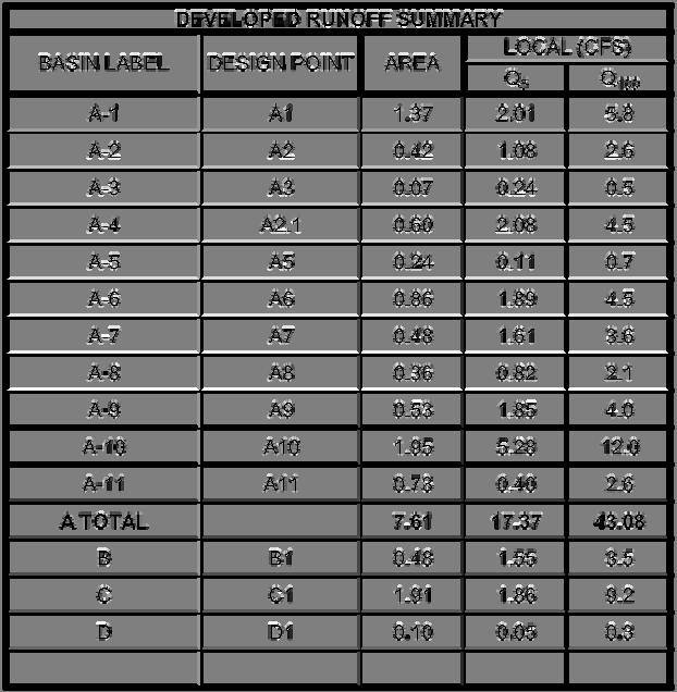


91