Reactive CFD model for the simulation of glass furnace combustion
|
|
|
- Silvester Bryant
- 5 years ago
- Views:
Transcription
1 Reactive CFD model for the simulation of glass furnace combustion Ing. Michele Pallante, Prof. Carlo Cravero Università degli studi di Genova, DIME 1
2 Factors that affect the combustion in glass furnaces Inside glass furnaces normally evolves a non deterministic flame (with respect to other application like gas turbine combustion), that is strongly subject to the variation of many characteristic parameters of the furnace: Operating point; Production Rate; Temperature and pressure distribution at the inlet (port exhaust section); Tilt and balance of the burners. These parameters are often strictly interconnected This generates an overlapping of effects in the flame structure that makes the understanding of the contribution of every single parameter actually impossible... CFD can be very useful to help this understanding process. 2
3 Towards I.R.M. (Industrial Routine Model) The aim of our research is to set up a Industrial Research Model in order to extract functional relations that give us the possibility to understand the response of the system in different situations. We have set up a reactive fluid dynamics simulation approach for the system using commercial software (Ansys FLUENT ) that we routinely use to help the design process of the furnace. The procedure can be used as a tool for design phase or for the validation and allows to: Estimate the flow structure with temperature and pressure fields; Estimate the temperature of the flame and waste-gas; Estimate the outgoing chemical species for pollutants trend prediction; To simulate the effectiveness of the emission reduction strategies through the gas recirculation technologies. 3

4 Combustion takes place in glass furnace has these characteristics Homogeneous: fuel, oxidiser and products are in gas phase; Characteristics of combustion in glass kilns Non-premixed: There are separate entrances of methane and air, which are mixed inside the oven; Turbulent: considering the size of the furnace and velocities the flow is turbulent. 4
5 Chemical - fluid interaction In turbulent regime the fluctuations of the velocity field increase the intensity of material and thermal exchange of the systems, thereby increasing the speed of reactions. The increase of chemical kinetics produces an increase in temperature of the system that influences the flow velocity and therefore the degree of turbulence; The flame is an extremely thin reaction zone that separe the transition between a stable mixture and a chemical equilibrium. In this area there is a very strong release of heat combined with a high dependency on temperature reactions that lead to a strong acceleration in a very narrow angle. Mixing increase Turbulence Combustion reactions Temperature increase Velocity increase 5
6 The goals of the thermo-chemical simulations are: Thermo-chemical simulations Predict the presence of carbon monoxide and NOx exit from the furnace; Investigate the effectiveness of lean burn combustion and staged combustion. For these reasons it is necessary to consider detailed chemical reactions, including the transport of each intermediate species that are formed during combustion. This means that thermochemical analysis of glass furnaces without a simplified approach can be very computationally intensive. In order to allow the simulation process to be effective during the furnace design process a simplified approach is selected: FAST CHEMISTRY APPROACH 6
7 Fast chemistry approach The fast chemistry approach it can be used only when the reaction are considered infinitely faster than the characteristics time of flow structure and turbulence. Usually for diffusive flames, as in the glass furnaces, the FAST CHEMISTRY approach is acceptable. This approach is good for the furnace but particular attention should be paid to NOx: The dynamics of reactions involving NOx is especially slow, and this may require the use of models that consider a finite reaction speed. Nevertheless NOx mass concentration is very limited, and therefore it can be assumed that their reactions do not influence the global fluid dynamics of the furnace. For the above reasons NOx can be calculated from the temperature and pressure fields obtained from the fast chemistry approach.
8 The IRM model The model is based on the use of commercial software for the simulation of the furnaces. 3d cad geometry Mesh Solver Output Model simplification of the furnace; Patch Assembly. Sizing of the calculation grid; Localized volume refinment settings. Settings of the boundary conditions; Settings of the combustion model; Setting of the characteristics of the fluid; Setting of the monitors of the calculation. Global Nox and CO values at the exhaust port; Contours of temperature and velocity on standard sections; Isovolume for NO x, CO, O 2 and CH 4.
9 Model ingredients For the simulation of combustion inside glass furnaces we use these models: Energy equation; Radiation (P1 model is based on expanding the intensity of radiation in a series of orthogonal spherical harmonics); Turbulent viscosity (k-ε model function with scalable wall function); Species model (non-premixed combustion) with Probability Density Function. The nonpremixed combustion model requires two input: oxidizer fuel; The flamelet model has been used for the creation of the PDF table with the CHEMKIN mechanism grimech 3.0.

10 3D model Theese approach is validated for endport furnaces with these boundary settings: Furnace top side Wall temperature Combustion Chamber volume Air port Waste gas port Furnace side wall Wall temperature Waste gas outlet Opening Glass free surface Wall temperature Methane inlets Velocity inlet Air inlet Mass flow inlet
.")
 to the order of millimeters (close to the methane")

11 Mesh settings For the simulation of combustion in the furnace it was created a hybrid mesh (structured + unstructured). The lengths span from the order of meters (in the combustion chamber) to the order of millimeters (close to the methane nozzle). For this reason a fully-structured approach has been avoided, preferring a hybrid mesh with smaller elements in the area of the methane entrance.


12 Applications The model was applied to three operating furnaces to calibrate and verify the validity of the calculations: TREZZANO 3 Fournaces ALTARE 2 Fournaces VETRI SPECIALI Fournaces
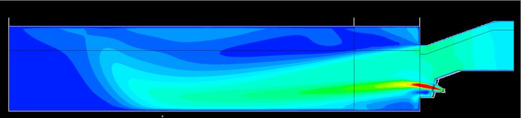
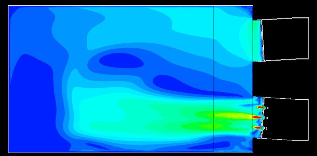
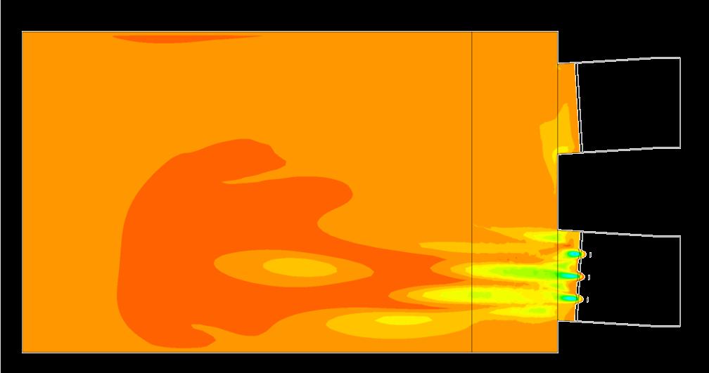

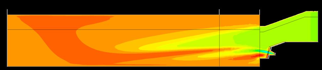
13 Applications example: Trezzano fournace nr. 3 Contours of velocity and temperature on meridian plane and longitudinal plane of the burner

14 Applications example: Trezzano 3 fournaces Isovolumes of CO mass fraction and CH4 mass fraction in the domain.
15 CO ppm NO 8% [mg/nm3] LIFE12 ENV/IT/ PRIME GLASS Effect of nozzle tilt on global emission variation Nozzle tilt ,50% 1,00% 1,50% 2,00% 2,50% 3,00% O2 fraction Tilt variation CO ppm 10 CO ppm 20 CO ppm 15 NO 8% [mg/nm3] 10 NO 8% [mg/nm3] 20 NO 8% [mg/nm3] General trend confirmed by CFD 1) The levels of CO and NOx are tightly connected with the percentage of oxygen in the waste gas. 2) CO Increases exponentially with the lowering of O2, the nitrogen oxides grow linearly with the Increase of O2 The tilt angle can be used to control the overall emissions in a given furnace
16 CO ppm NO 8% [mg/nm3] LIFE12 ENV/IT/ PRIME GLASS Effect of burner activation on global emission variation Different burner activation burners burners ,50% 1,00% 1,50% 2,00% 2,50% 3,00% O 2 fraction CO ppm 3 burners CO ppm 2 burners NO 8% [mg/nm3] 3 burners NO 8% [mg/nm3] 2 burners The different burner activation can be used to control the overall emissions in a given furnace
; Lower order models for combustion simulations (0D -1D); Under develpoment from existing simulation codes")
17 Radiation model and gas emissivity model; Model extentions: work in progress Under testing using the experimental SANDIA diffusive flame; Complete multispecies reaction model; Under testing using the experimental SANDIA diffusive flame; Reaction zones and detailed kinetics (Ansys Energico); Lower order models for combustion simulations (0D -1D); Under develpoment from existing simulation codes developed for gas turbine combustion.