Status of Conformal Cooling for Injection Molds
|
|
|
- Myra Crawford
- 5 years ago
- Views:
Transcription
1 Status of Conformal Cooling for Injection Molds William Sames, Ph.D., CEO HTS International Corporation htsintl.com Solway School Rd Ste 103 Knoxville, TN 37931


2 About HTS International The HTS mission is to advance the productivity of mass production We provide complete thermal management solutions for injection molding and die casting Our customers save cycle time, boost productivity Our tooling blanks helps US customers compete with overseas producers We supply inserts, sprue bushings, gate pads, and hot runner manifolds for injection molding itherm TM is the engineered approach that HTS IC takes towards implementing conformal cooling and internal passageways

3 About HTS International HTS International Corporation has HQ offices in the USA (main) and Austria (EU), production facilities in Italy and Slovenia, and sales offices in the Czech Republic, Germany, Poland, Spain, and Sweden.
4 TECHNOLOGIES FOR CONFORMAL COOLING
5 Business Models Influence the Supply 1. Toolmakers Chain of Conformal Cooling Offer in-house capabilities to sell more tooling Presents turn-key solution for molders 2. Contract Conformal Cooling Providers Offer near-net shapes or blanks that toolmakers then integrate into tools/molds, typically as inserts/cores Typically heat treaters, metal AM service bureaus
6 Technologies for Conformal Cooling 1. Powder bed fusion (SLM, DMLS, Cusing, etc.) 2. Groove milling + o-rings 3. Brazing/bonding/silver solder 4. Other, Proprietary Techniques (imft, etc.)

7 Conformal Cooling via 3D Printing has been Tried Since the Early 1990 s About the tests: Run by MIT in 1995 Printed binder onto Stainless Steel powders to form shape Compared mold surface temp to conventional machined, straight cooling lines SOURCE: E. Sachs et al., MIT, 1995
8 Conformal Cooling Today: AM Most molding applications utilize Powder Bed Fusion (SLM, DMLS, Cusing, etc) Technology typically applied by melting powder layers on top of a machined based Size range: Up to 500 x 300 x 400mm build volume, but processing challenges means this is typically not maximized Cost, Lead Time: Pricing ~$2000/kg of printed material + post-processing Print speed ~24 hr/kg Source: KEY QUESTIONS TO ASK WHEN USING PBF TECHNOLOGY: Is post-processing included in quote? HIP? What happens if material failures occur? Will machined base fit into build volume? Available alloys? Is cooling channel design optimized for printing OR optimal for mold cooling? Will it be coated?
9 Next Steps for CC Industry Consistent evaluation for new projects Better/quicker understanding of ROI in mold building timeline Integration of post-processing, reliable lead times Quality guarantees/warranties QC = leak, flow testing prior to delivery; hardness; material certs Focus on application NOT process

10 Setting a New Standard in Mold Cooling HTS is developing standard products with conformal cooling First lines in plates, sprue bushings, gate pads Lowers costs Off-the-shelf designs Shorter lead times
11 APPLICATION: GATE PAD

12 Gate Pad Seat for the hot runner nozzle Come in various sizes/shapes depending on nozzle and tool design Usually does not have cooling This example has cooling on outside surface around midsection between two o-rings


13 itherm Concept Cooling channel inlet/outlet on same surface as conventional cooling Wraps cooling channel around injection nozzle tip Design of gate pad might have to be modified to fit cooling channels

 Heat flux = 150,000W/m^2")
 h = 3,000 W/m^2K at 310K")
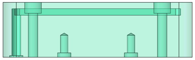
14 Steady State Thermal FEA setup Conventional and itherm inserts run with same boundary conditions Heat Flux on surfaces (shown in light blue) Heat flux = 150,000W/m^2 Cooling Convection in channels (shown in dark blue) h = 3,000 W/m^2K at 310K Conventional Cooling
15 Terminology Definitions Peak Temp. = max temperature in the steady-state solution; this is a qualitative measure to compare between cases, but does not necessarily represent an absolute temperature Avg. Body Temp. = the average temperature of the component in the steady-state solution; again, this value is for comparison between simulations results only


16 Steady State Thermal FEA: Gate Pad Results Body Temps: Average = 73 C Peak = 270 C Body Temps: Average = 48 C Peak = 189 C Conventional itherm
17 R&D EFFORTS ON FLAT PLATES, SPRUE BUSHINGS
18 Design of Cooling Channels: Defining Cooling Power Mold inserts can be defined by Cooling Power, or the amount of heat removal capacity that an insert possesses at the molding surface HTS recommends that the first stage in designing cooling channels is to set the depth from the molding surface The optimal spacing of cooling channels can then be found from basic math or a table of values


19 HTS, ORNL, IACMI Participate in Joint Project to Explore Conformal Cooling Applications Initial scope of project aims to understand impact of conformal cooling vs. conventional cross-drilling on molding of flat products A mold for an ice scraper was developed for testing purposes


20 HTS, ORNL, IACMI Design of Experiments 0.5W 20W 0.5W 0.5W 0.5W 5W 10W 20W

21 Metrology Defines Successful Parts: Deviation/Warping When Cooling is Insufficient

22 HTS, ORNL, IACMI Testing of Standard itherm TM Products: Initial Results 34-54% Cycle Time Reduction

23 Conformal Cooled Plates Help Move Cooling Closer to Surface, while Maintaining Mold Strength Reduction of up to 70% of cycle time for flat parts Increase in cooling uniformity Cooling arrangement of plates has been optimized and compared to the conventional Basic Model


24 Conformal Cooled Plates Reduce Temperature Variability of the Molded Part Plates and other conformal cooling components can be defined by cooling intensity Graph of the temperature gradient between various cooling geometries is shown Reducing the temperature difference helps improve part quality, reduce warping


25 Sprue Bushings for Cold Runner Systems 53% Thermal Performance Index Sprue Bushing Conventional itherm TM Bottom Connectors itherm TM Side Connectors Conventional Temp. at Ejection itherm TM Temp. at Ejection


26 Moldflow for Thin-Walled Part Shows Sprue Bushing Increases Productivity, Does Not Freeze During Fill Conventional itherm TM Sprue freezes after part during fill Note that the axes are different. The red line is at part center. Cycle time reduced from 54s to 43s, or 20% for this case.
27 TRANSIENT NUMERICAL SIMULATION OF SPRUE BUSHING


28 Simplified Models for Simulation using Abaqus Conventional model itherm
29 Temperature [ C] Thermal Coefficient [W/m^2K] Cycle Properties Temp_Plastic Hex_Plastic Filling Cooling Part ejection Time [s]
30 Conventional model itherm
31 Conventional model itherm


32 Conventional model itherm
![Temperature [ C] Temperature [ C] Surface Temperature Comparison 130 Conventional 110 90](/docs-images/88/114825339/images/33-2.jpg "70 50 30 130 110 0 20 40 60 80 100 120 140Time [s] Conventional Model 90 70 50 30 Time")
33 Temperature [ C] Temperature [ C] Surface Temperature Comparison 130 Conventional Time [s] Conventional Model Time saving

34 Automotive Case Study: DENSO Electronics Mold for thin parts for dashboard components Operates on cold runner system, 4x cavities Sprue was limiting cycle time for customer Original sprue bushing was steel, with no cooling

35 Automotive Case Study: DENSO Electronics Conformal cooling was proposed for sprue bushing to remove excess heat from sprue During first trials, sprue cooling power was too high and the cavity did not completely fill During final test, the cooldown time was reduced from 20s to 15s which resulted in about a 14% reduction in cycle time (cycle time dropped from ~36 seconds to ~31 seconds)


36 Case Study: Cutlery


37 Case Study: Cutlery 23-41% Cycle Time Reduction The cycle time was cut from 6.5s to 3.8-5s Savings of s per cycle reported by customer Customer satisfied with performance The achieved results were better than predicted from FEA analysis


38 Case Study: 90 Degree Pipe Fitting Elbow Simulation predicted itherm inserts to shorten cycle time from 257s to 125s, double the productivity itherm TM Standard


39 Conformal Cooling Eliminates Hot Spots, Reduces Scrap Rate Current cooling solution Cycle time: 257 s itherm cooling solution Cycle time: 127 s


40 Case Study: 90 Degree Pipe Fitting Elbow
41 Case Study: 90 Degree Pipe Fitting Elbow 54.7% Cycle Time Reduction The cycle time was cut from 256s to 116s Savings of 140s per cycle Customer is implementing itherm TM for other components now The achieved results were better than predicted from FEA analysis

42 Contact Us Will Sames, CEO htsintl.com c: Solway School Rd Ste 103 Knoxville, TN 37931