Biogas Treatment Systems
|
|
|
- Jeffrey McDowell
- 5 years ago
- Views:
Transcription


1 Biogas Treatment Systems Biogas treatment system allows for purification of biogas up to biomethane condition (complete analog of natural gas with methane concentration in the range of 90-97%). After treatment biogas can be used as vehicle fuel or to be fed in to the general natural gas grid. 1
.")

2 Regeneration Step. A small amount of product hydrogen is used to flush the waste gas through an exhaust port, preparing the vessel for another production cycle. Make Fuel for any NGV Technology for biogas upgrading is based on a simple and long-standing gas separation and purification process, pressure swing adsorption (PSA). PSA is a commonly used technology for purifying gases. PSA technology was introduced commercially in the 1960's and today PSA is used extensively in the production and purification of oxygen, nitrogen and hydrogen for industrial uses. PSA is based on the capacity of certain materials, such as activated carbon and zeolites, to adsorb and desorb particular gases as the gas pressure is raised and lowered. PSA can be used to separate a single gas from a mixture of gases. A typical PSA system involves a cyclic process where a number of connected vessels containing adsorbent material undergo successive pressurization and depressurization steps in order to produce a continuous stream of purified product gas. The PSA process is used to separate hydrogen from a feedstock gas containing impurities, such as carbon dioxide, carbon monoxide or water. Production Step. The contaminated feedstock gas is pumped into a cylinder at pressure. The cylinder contains beads of adsorbent material. The impurities in the feedstock gas, such as carbon dioxide, are adsorbed onto the internal surfaces of the adsorbent beads, leaving hydrogen in the vessel, most of which is removed as purified hydrogen product. Pressure in the cylinder is reduced, releasing the impurities from the adsorbent material. Conventional PSA systems used today in industry are made up of four to 16 large vessels, connected by a complex network of piping and valves to switch the gas flows between the vessels. Despite their widespread use in industry, we believe that large scale PSA systems suffer from a number of inherent disadvantages. These PSA systems typically operate at slow cycle speeds of cycles/minute since faster cycle speeds would cause the adsorbent beads to float or "fluidize" in the vessel, causing the beads to wear and ultimately fail. To meet customer demands for capacity conventional PSA systems must utilize large vessels to compensate for the slow cycle speeds, leading to higher costs and a large equipment footprint. The use of large vessels also means that these PSA systems are typically erected in the field, increasing installation costs. The network of piping and valves used in large scale PSA systems, with the associated instrumentation and process control equipment, also adds cost to the overall system. Our proprietary structured adsorbent material avoids the fluidization limitation of beaded adsorbents, allowing our PSA systems to operate at significantly higher cycle speeds (up to 50 cycles/minute) than conventional PSA systems. This results in a direct reduction in the amount of adsorbent material and the size of equipment that is required to purify a given volume of product gas. In addition, our proprietary rotary valve technology replaces the complex and bulky network of piping and valves used in conventional PSA systems with two compact, integrated valves. 2


3 One of the most efficient systems of anaerobic digestion biogas treatment is regeneration system. The working principle for that system includes two technological processes CO2, H2S and moisture removal. Inlet biogas is initially compressed to operational pressure 8-10 bar. Then biogas directed to purification column and purified with cooled water under pressure. Water is supplied from cooling system from the top of the column in the reverse direction to the biogas flow. In that way СO2 and H2S admixtures are removed in purification column thanks to their solubility in water if to be compared to methane. Column is filled with special material in order to secure good throughput capacity and heat conductivity. The purification process is most efficient when water has low and constant temperature. For that purpose cooling system is included into the technological process. Water that is used for biogas purification contains dissolved methane and other gases that is why it is compressed to 2 bars and directed to methane regeneration column. Gas is extracted from the water and supplied to the inlet of the treatment system for purification and recirculation. 3


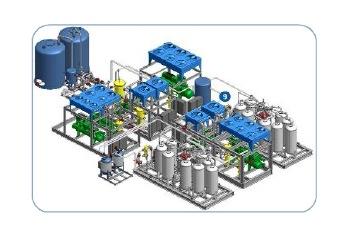
4 Methane losses can be controlled by adjustment of pressure in the regeneration column. Methane regeneration from the water is performed in 3 ways: 1. recuperated gas saturated with CO 2, H 2 S and CH 4 is directed to big purification circle with second compression at inlet compressor. 2. Gas extracted from the bottom of the column also directed to initial compression stage. 3. Recalculated water is directed to gas separation column for CO 2 and H 2 S removal by air. Air and water form gas separation column is directed to bio filtration column which is filled with plastic balls that areused as bacteria carrier. As a result of intensive mixing bacteria removes remnants of H 2 S and CO 2. Microorginizm removed from the balls come out as sludge. 3D model of biogas treatment unit 250 m 3 /h capacity Gas drying system is installed after the purification columns which consist of a drying module, carbon filter. This system removes water remnants from a purified gas. Drying unit is self-cleaning and completely controlled by electronic system. For optimum process control levels of CO 2, CH 4, H 2 O, H 2 S and Wobbe-index are constantly fixed by electronic system, the results are displayed at system monitor. The advantage of this system is low cost for biogas treatment due to usage of water as a main purification element. Biogas treatment unit 500 m 3 /h capacity 4


5 5