Experimental Measurements for Plate Temperatures of MTR Fuel Elements at Sudden Loss of Flow Accident and Comparison with Computed Results
|
|
|
- Clifton Allison
- 5 years ago
- Views:
Transcription
1 Experimental Measurements for Plate Temperatures of MTR Fuel Elements at Sudden Loss of Flow Accident and Comparison with Computed Results Dr. Bülent SEVDIK TR 2 Reactor Unit Head Turkish Atomic Energy Authority, CNAEM, Istanbul, Turkey
2 The aim of this study: To generate experimental data to be used for sensitivity analysis and assessment calculations on the thermal hydraulic codes written for Loss of Flow Accident (LOFA) analysis of research reactor with MTR type (plate type) fuel elements.
3 How does it Happen: In an open pool research reactor with downward coolant flow, an accident such as shaft breaks between pump and flywheel can lead to sudden loss of flow.
4 In the TR 2 Research Reactor; Sudden Loss of Flow Accident is simulated by closing the pool inlet valve. It is a butterfly type valve and total closing time is about 30 seconds but effective flow decrease occurs in 10seconds. The beginning of the flow decrease by the closing of valve was accepted as zero time and decrease curve of flow rate versus time was plotted.


5 Beginning of flow decrease
6 Pool Inlet Valve V214 Heat Exchanger Cooling Towers Pool Reaktör Havuzu Tampo n Tank Secd. Pump TR-2 Core Primary Pumps V301 V201 Delay Tank 22 m3-3min TR-2 Reactor Cooling Systems
7 Power distributions of the fuel elements in the reactor core were determined experimentally by using copper wire activation technique. According to the existing core loading of the TR 2 Reactor; core positions power distributions (U 235 weights, relative flux dist.) of the fuel elements were given for the inputs of the calculations to simulate the LOFA at the (PARET) computer codes.
8 Instrumented Fuel Element: An instrumented fuel element, which has five thermocouples along the vertical direction of the fuel plate, was used for the experiments. Instrumented Fuel Element top view. 23 Fuel Plates Thermo-couples are placed on second fuel plate (first cooling channel) (Cooling gap:2.1 mm)
9 71mm top Fuel Meat 0.51 mm TC1 TC2 29mm 266 mm 366 mm Plate Thichness: 1.27 mm TC3 466mm 591mm TC4 625mm Fuel Clads 0.38 mm TC5 Foot Location of the Chromel Alumel Thermocouples on Fuel Plate of the Instrumented Fuel Element
10

11 TR-2 Core Configuration BE WB WB Instrumented Fuel Element was Placed. WB SI-01 WB Punom atic


12
13 Experiments: Four experiments were performed for SLOFA. Three of these experiments were repeated with different initial conditions such as different core inlet temperatures and different reactor operation times at 5 MW nominal power level and 750 m3/h primary flow rate. The reactor was shutdown by flow scram at these three experiments. Last Exp.was performed without scram. (Nötronic Power:50 kw)
14 1. Experiment P=5 MW Total reactor operation time is 5 minute before scram Initial flow rate: 750 m 3 /h (reverse flow) Pool Water temperature : 23 o C (Core inlet)
15 2. Experiment P=5 MW Total reactor operation time is 5 minute before scram Initial flow rate: 750 m 3 /h (reverse flow) Pool Water temperature : 17 o C (Core inlet)
16 3. Experiment Natural Convection P=5 MW Total reactor operation time is 2 hours before scram Initial flow rate: 750 m 3 /h (reverse flow) Pool Water temperature : 29.5 o C (Core inlet)
17 4.Experiment No Scram P= 50 KW Neutronic Power Total reactor operation time is 5 minutes before flow decrease Without SCRAM Initial flow rate: 750 m 3 /h (reverse flow) Pool Water temperature : 19 o C (Core inlet)
18 1. & 2. EXPERIMENT P=5 MW Total reactor operation time is 5 minute before scram Initial flow rate: 750 m 3 /h (reverse flow) They are compatible
19 5 Minutes 5 MW Power Operation Pool Water: 23 o C 2 Hours 5 MW Power Operation Pool Water: 29.5 o C
20 5 Minutes 5 MW Power Operation Pool Water :23 o C 2 Hours 5 MW Power Operation Pool Water :29.5 o C 45 sec
 Initial Flow Rate: 750 m 3 /h Pool Water Temperature: 17 o C")
21 Decreased Decay Heat 90 sec 110 sec For Paret Calculations : P=5 MW, Reactor operation time before scram 5 minutes at 1 MW, (to decrease decay heat at the calculations) Initial Flow Rate: 750 m 3 /h Pool Water Temperature: 17 o C

22 Decreased Decay Heat 90 sec 52 sec 5 Minute Power Operation at 1 MW and 5 MW before SCRAM Pool water temperature: 17 o C 5 Minute Power Operation at 5 MW before SCRAM
23 Conclusions: Residual decay heat calculation and the natural convection modeling for narrow rectangular channels of PARET code are not quite realistic. PARET uses the standard fission product decay heat curve for uranium fuelled thermal reactors published by the American Nuclear Society as a proposed standard (ANS 5.1/N18.6). ANS d h t i t i i ti
24 For the calculation of the residual decay heat, special attention must be given to the fact that Approximately one half of the decay heat is due to gamma radiation with energies in the range of about MeV. The e folding length for 1 MeV gamma radiation in aluminum is 6 cm, i.e., the source gamma intensity is attenuated to 1/e of its original value after passing through 6 cm of aluminum.
25 This corresponds to a penetration of fuel plates and hence shows that a significant portion of a given level of fuel element decay heat will be deposited at the outside of the fuel element. Realistic calculations can be done for LOFA and LOCA analysis by using the decreased (1/2) values of decay heat generation curve of ANS.
26 Thank you very much

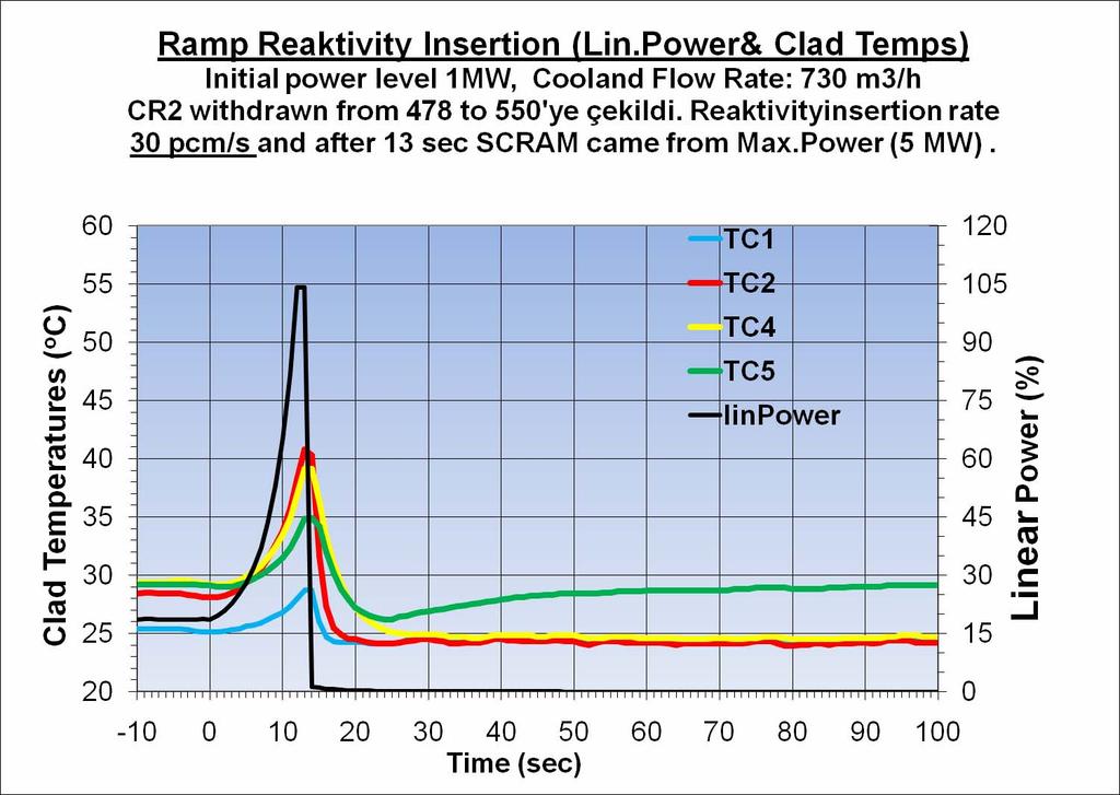
27 Max Power 700kW

28 Period scram 4.2 sec

29
30