Gasification Technologies
|
|
|
- Bryce Wheeler
- 5 years ago
- Views:
Transcription


1 Gasification Technologies ThyssenKrupp Uhde
 10 The PRENFLO process (PDQ) 12 The HTW process 14 Major Projects 16 Range of Services - Technologies 20 - Serving our Customers 22")
2 2 Table of contents Gasification 04 Feedstocks 06 Syngas applications 08 ThyssenKrupp Uhde's experience in gasification 09 The PRENFLO process (PSG) 10 The PRENFLO process (PDQ) 12 The HTW process 14 Major Projects 16 Range of Services - Technologies 20 - Serving our Customers 22 Contacts 23


3 3 Company profile With its highly specialised workforce of more than 5,600 employees and its international network of subsidiaries and branch offices, ThyssenKrupp Uhde, a Dortmund-based engineering contractor, has, to date, successfully completed over 2,000 projects throughout the world. ThyssenKrupp Uhde s international reputation has been built on the successful application of its philosophy Engineering with ideas to yield cost-effective, high-tech solutions for its customers. The ever-increasing demands placed upon process and application technology in the fields of chemical processing, energy and environmental protection are met through a combination of specialist know-how, comprehensive service packages, topquality engineering and deadline reliability. The extensive international experience in the design and construction of chemical plants makes ThyssenKrupp Uhde the ideal licensor and engineering contractor for gasification plants. ThyssenKrupp Uhde s head office Dortmund, Germany
4 4 Gasification Why gasification? Gasification processes offer a number of upstream and downstream advantages to customers faced with rising oil prices and dwindling energy reserves as well as a need to meet increasingly stringent environmental requirements. With proper preparation a variety of carbonbased materials can be easily gasified to produce synthesis gas (syngas) for the subsequent production of chemicals, liquid fuels, electricity or direct reduction gas (DRI). Gasification is particularly clean and efficient.

 and in the production of liquid fuels (gasoline, diesel, etc.). Gasification technology offers environment-friendly, efficient solutions for these applications.")
5 5 Gasification is also flexible with respect to feedstock quality and the use of mixed feedstocks. The gasification of low-value or waste materials is an attractive option. Even otherwise problematic materials can be gasified together with the main feedstock. As coal is much more abundant than oil and gas and global availability ensures security of supply and relative price stability for the foreseeable future, coal will play an ever greater role in power generation, the chemical industry (e.g. in India, China and Africa) and in the production of liquid fuels (gasoline, diesel, etc.). Gasification technology offers environment-friendly, efficient solutions for these applications. In power generation, for example, gasification can achieve high thermal efficiencies and also forms a basis for Carbon Capture and Storage (CCS). A number of chemical reactions are involved, some exothermic and some endothermic: Exothermic: C + ½ O2 CO C + O2 Endothermic: C + CO2 2 CO C + H 2O CO2 CO + H2 During the gasification process, the sulphur present in the feedstock reacts to produce mainly hydrogen sulphide (H2S) and carbonyl sulphide (COS): S + H2 H2S S + C + ½ O2 COS ThyssenKrupp Uhde s proprietary HTW and PRENFLO technology provide tailor-made gasification solutions optimised for the respective project-specific application: Sulphur can therefore be readily recovered in its elemental form or as sulphuric acid, both marketable commodities. HTW: fluidised-bed gasification PRENFLO with Steam Generation (PSG): entrained-flow gasification PRENFLO with Direct Quench (PDQ): entrained-flow gasification Worldwide Gasification Capacity and Planned Growth Commulative by Year What is gasification? Gasification is mainly a high-temperature partial oxidation process for converting carbonaceous materials into a synthesis gas composed mainly of carbon monoxide and hydrogen.
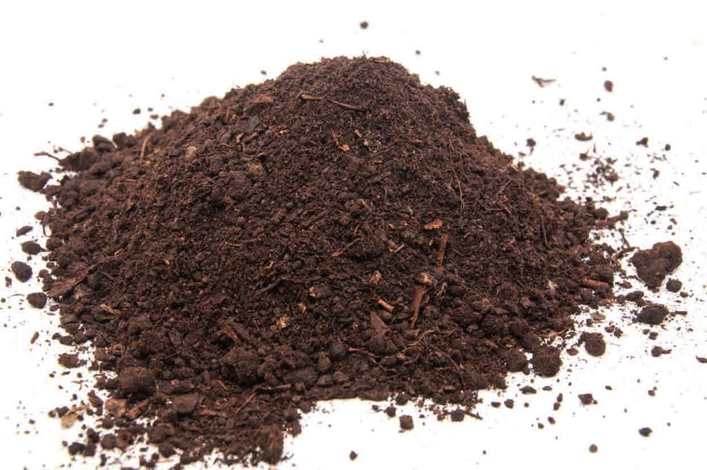
6 6 Feedstocks ThyssenKrupp Uhde s gasification technologies are all based on dry feeding principle, and are thus able to handle all types of coal (hard coal, lignite, anthracite, high-ash coals, coals with high-ash melting points) as well as petroleum coke, char and biomass (e.g. wood, chicken litter, sewage sludge, olive residues, etc.). In addition to the main product (syngas), gasification produces by-products of economic value. The gasification of solids produces: bottom ash, fly ash and, after subsequent gas treatment, elemental sulphur or sulphuric acid. Range of feedstocks ThyssenKrupp Uhde's gasification technologies are suitable for a wide range of feedstocks, such as: Hard coals (with low and high ash contents) Brown coal, lignite Petroleum coke Biomass Wastes Different feedstocks require different gasification technologies n PRENFLO Entrained-Flow Gasification Ori mu lsi on Na ow e l ph Wastes Oil Gasification as u ra l G HTW (High-Temperature Winkler) Fluidised Bed Gasification Nat Biom tha ass Br nit l Petcoke Resid d Coa ues Oi Co al Lig Har


7 7
8 8 Syngas applications The raw gas produced by gasification needs to be treated before it can be used for the production of downstream products, such as hydrogen, SNG, ammonia, methanol, liquid fuels, electricity or direct reduction gas (DRI). There are various process routes available for obtaining the desired syngas composition, which may be a mixture of carbon monoxide and hydrogen or either pure hydrogen or carbon monoxide alone. A number of processes are available for desulphurisation and carbon dioxide removal, such as: MDEA, amdea, Genosorb, Selexol, Sulfinol, Rectisol. Hydrogen, for example, can be used in the refinery industry to achieve lighter and cleaner liquid fuels or for new applications such as fuel cells for power generation or cars. For the production of ammonia synthesis gas, a liquid nitrogen process can be used for the final cleaning and to obtain the correct mixture of hydrogen and nitrogen. Hydrogen-rich syngas can be produced via the sour CO shift process. In this case, the CO in the raw gas produced by gasification is shifted with steam to form hydrogen and carbon dioxide before the sour gas components are removed. ThyssenKrupp Uhde offers all of these process stages and can provide optimised solutions for complete production plants for e.g. fertilisers or liquid fuels as well as for combined hydrogen and electric power generation with or without carbon dioxide capture, or for direct reduction in the steel industry (DRI). MTO Diesel Naphtha MTG Gasoline LPG Methanol Gas Naphtha Oil ThyssenKrupp Uhde Steam Reformer Urea Ammonia Orimulsion Residues Petcoke Hard Coal PRENFLO Gasification Lignite Biomass Brown Coal Waste Diesel Naphtha FischerTropsch Waxes Lubes H2 SNG HTW Gasification IGCC/ Power Reduction Gas

9 9 ThyssenKrupp Uhde's experience in gasification ThyssenKrupp Uhde's gasification history Different technologies for different applications
10 10 The PRENFLO Process with Steam Generation (PSG) The PRENFLO (PRessurised ENtrained-FLOw) process, which operates at elevated pressure, can be used to gasify all types of solid feedstocks (coal, petroleum coke and biomass). It is a further development of the Koppers-Totzek process developed in the 1940s, which operates at atmospheric pressure. Flow diagram of the PRENFLO (PSG) process Main process data: Gasification pressure: 40 bar and higher Gasification temperature: > 2,000 C Gas temperature at outlet of gasifier: 1,350-1,600 C Carbon conversion: > 99 % Typical raw gas composition: CO + H2 > 85 vol. % CO2 2-4 vol. % CH4 < 0.1 vol. % PRENFLO can look back on more than two decades of operating experience, providing a wealth of lessons learnt which have formed the basis for subsequent successful applications.

11 11 PRENFLO gasifier/boiler (PSG) Process description First, the feed dust is prepared in the feed preparation unit. Approximately 80% of the dust is smaller than 0.1 mm and has a water content of approx. 1-2 wt.% in the case of hard coals and approx wt.% in the case of lignite. This feed dust is then gasified in the PRENFLO gasifier using oxygen and steam as gasification agents. The gasification temperature is higher than the ash melting temperature, which allows the coal ash to be removed as slag. The cooled-type gasifier is equipped with multiple, horizontally arranged burners. In the PRENFLO Process with Steam Generation (PSG), the raw gas produced, which contains mainly carbon monoxide and hydrogen, is cooled in the waste heat boiler, generating steam. The gas is then dedusted in a candle filter and further treated in a Venturi scrubber. Quench gas Oxygen Feed The slag from the gasifier can be used as a construction material and the fly ash from the candle filter as a base product in the cement industry. PRENFLO technology is used at the world s largest solid-feedstock-based IGCC power plant in Puertollano, Spain. This plant operates with a mixture of petroleum coke and coal. The following tables show the feedstock composition and an analysis of the raw gas produced. Slag Raw gas Raw Rawgas gasanalysis analysispdq PSG ppmv ppmv Main features of the PSG process: Entrained-flow Dry dust feed for high efficiency Multiple burners with high availability and long lifetime Horizontally arranged burners for high carbon conversion Membrane wall with long lifetime Waste heat boiler for efficient heat recovery Operates above ash melting point
12 12 The PRENFLO Process with Direct Quench (PDQ) The PRENFLO (PRessurised ENtrained-FLOw) Direct Quench (PDQ) process is an optimised design of the proven PSG gasification process for chemical applications (e.g. ammonia, methanol, hydrogen, synthetic fuel) and IGCC plants with Carbon Capture and Storage (CCS), where hydrogen-rich syngases are required. It combines the technologically advanced dry feed system, multiple burners and Flow diagram of the PRENFLO (PDQ) process Main process data: Gasification pressure: 40 bar and higher Gasification temperature: > 2,000 C Gas temperature at outlet of gasifier/quench: C Carbon conversion: > 99 % Typical raw gas composition: CO + H2 > 85 vol. % CO2 6-8 vol. % CH4 < 0.1 vol. % membrane wall of the PRENFLO PSG process with a proprietary water quench system which saturates the raw syngas with water for subsequent gas treatment. Capital-intensive systems, such as the waste heat boiler system, the dry fly ash removal system and the quench gas compressor, are therefore no longer required.


13 13 PRENFLO gasifier/ Direct Quench (PDQ) Process description First, the feed dust is prepared in the feed preparation unit. Approximately 80% of the dust is smaller than 0.1 mm and has a water content of approx. 1-2 wt.% in the case of hard coals and approx wt.% in the case of lignite. This feed dust is then gasified in the PRENFLO gasifier using oxygen and steam as the gasification agent. The gasification temperature is higher than the ash melting temperature, which allows the coal ash to be removed as slag. The cooled-type gasifier is equipped with multiple, horizontally arranged burners. Oxygen Feed The raw gas produced, which contains mainly carbon monoxide and hydrogen, is quenched with water in the gasifier/direct quench and then cleaned in a scrubber. Raw gas The filter cake from the slurry filtration system is mainly recycled to the gasifier via the feed preparation unit. The slag from the gasifier can be used as a construction material. Slag Layout comparison of PRENFLO PSG and PRENFLO PDQ Main features of the PDQ process: Raw Rawgas gasanalysis analysispdq PDQ ppmv ppmv Entrained-flow Dry dust feed for high efficiency Multiple burners with high availability and long lifetime Horizontally arranged burners for high carbon conversion Membrane wall with long lifetime Full water quench for syngas saturation Shorter supply and construction schedule Lower investment cost Operates above ash melting point
14 14 The HTW process The fluidized-bed gasification process was developed in the 1920 s in Germany by Fritz Winkler. Commercial-scale Winkler gasifiers were operated in over 40 applications around the world. In the 1970 s, ThyssenKrupp Uhde together with Rheinische Braunkohlenwerke AG commenced with the development of a pressurised version of the Winkler gasifier the High-Temperature Winkler (HTW) gasification process. The HTW process enables shorter residence time, higher reaction velocity, higher reactor throughput for larger plant capacity, higher carbon conversion rate, higher plant efficiency and improved syngas quality. In 1978, the HTW pilot plant started-up in Frechen, Germany, with a pressure of 10 bar. The operating experience gained therein laid the foundation for the design and construction of the HTW commercial-scale plant at Berrenrath, which started-up in 1986 to convert Rhenish brown coal into methanol. The Berrenrath plant achieved plant availabilities of over 8,000 hours Flow diagram of the HTW process Main process data: Gasification pressure: bar Gasification temperature: C (below ash softening point) Carbon conversion: > 95 % per year. In 1988, another commercial HTW gasification plant started-up for Kemira in Oulu, Finland. This plant converted 100 % biomass (peat) into ammonia. Within the further development of the HTW process for IGCC applications, and the later engineering for the KoBra IGCC plant at Hürth, an additional 25 bar HTW gasification plant started-up in 1989 at Wesseling. In the mid-1990 s the HTW plant at Wesseling was operated using air instead of oxygen as reactant. Carbon conversion efficiencies up to 95 % could be achieved. Around the same time, the HTW plant at Berrenrath ran a programme to add up to 50 % of plastic wastes as feedstock to the gasifier. Due to the excellent results, Sumitomo Heavy Industries selected the HTW process for a municipal solid waste gasification plant that started up in Japan in Niihama in Today, HTW projects are under design and development e.g. in Sweden, India and Australia.

15 15 Raw Gas Process description In the fluidized bed, a high material and energy transfer rate is achieved and this ensures a uniform temperature distribution throughout the gasifier. The temperature is maintained below the ash softening point. Screw conveyers or gravity pipes are used for supplying the feedstock to the HTW gasifier. Due to the gasifier pressure, both the feeding system as well as the bottom ash removal have to be performed by lock-hopper systems. The gasification agents, steam and oxygen (or air) are injected at the bottom of the gasifier (here they serve simultaneously as fluidizing agents for the fluidized bed) and they are also introduced into the fluidized bed as well as above the fluidized bed, into the so-called post-gasification zone in order to improve the gas quality and the conversion rate due to the temperature increase. Feed Feed Gasification Agent Oxygen + Steam Air Feedstock Low Ash Lignite High Ash Lignite CO H2 CO2 CH2 N2+Ar H2O H2S NH3 vol.% vol.% vol.% vol.% vol.% vol.% vol. ppm vol. ppm ,000 1,500 Gasification Agent , Ignition Burner Ash Ash Main features of the HTW process: Fluidised bed Operates below ash softening point Dry feeding system Cyclone Post-gasification zone Multiple oxygen nozzles
16 16 Major Projects ELCOGAS S.A. Puertollano, Spain Capacity: 181,000 Nm3/h of raw gas (PRENFLO gasification)


/h (dry) CO")
/h (dry) CO + H2 PRENFLO")
/h (dry) CO + H2")
17 17 Coal-to-Liquids (MTG) Jincheng Anthracite Coal Mining, Shanxi, China Capacity: 2,600 barrels per day Gasification plant for the production of ammonia and methanol Modderfontein, South Africa Capacity: 90,000 m3 (Vn)/h (dry) CO + H2 Gasification plant for the production of oxo gas Oberhausen, Germany Capacity: 83,000 m3 (Vn)/h (dry) CO + H2 PRENFLO demonstration plant Fürstenhausen, Germany Capacity: 4,200 m3 (Vn)/h (dry) CO + H2
 In combination with ThyssenKrupp Uhde s gasification technologies, different process routes for the production of liquids from coal or other carbonaceous feedstocks, i.e. the Methanol-to-Gasoline (MTG) route or the Fischer-Tropsch synthesis route, can be supplied.")

18 18 Major Projects Coal-to-Liquids Wesseling, Germany Capacity: 100 barrels per day IGCC plant for electric power generation Puertollano, Spain Capacity: 183,000 m3 (Vn)/h (dry) CO + H2 Methanol-to-Gasoline (MTG) In combination with ThyssenKrupp Uhde s gasification technologies, different process routes for the production of liquids from coal or other carbonaceous feedstocks, i.e. the Methanol-to-Gasoline (MTG) route or the Fischer-Tropsch synthesis route, can be supplied. Elcogas IGCC Plant This IGCC plant is based on a highly integrated system in which the total air for the air separation unit is taken from the gas turbine compressor. The plant can be divided into three main parts: the gasification island, comprising the feed preparation unit, the PRENFLO gasification unit, the gas treatment unit and a sulphur recovery unit the power block, comprising the gas turbine, the heat recovery steam generator and the steam turbine the air separation unit (ASU)


19 19 Waste gasification plant Niihama, Japan Capacity: 48 t /d Municipal solid waste HTW Gasification On the basis of the preliminary tests in a bench-scale plant at Aachen Technical University, a pilot plant has been set up by Rheinbraun in their coal processing factory Wachtberg at Frechen near Cologne in order to test the HTW process. This project was subsidized by the Federal Ministry for Research and Technology (BMFT). ThyssenKrupp Uhde was responsible for the engineering, supervision of civil works and erection activities and for commissioning the plant. ThyssenKrupp Uhde and Rheinbraun engineers jointly perform the tests and evaluate the resultats. The pilot plant was commissioned in summer The test programme covered the evaluation of the process design parameters, in particular: Gasification under pressure Gasification at evaluated temperature Improving the carbon conversion rate Improving the gas quality The Rheinbraun HTW demonstration plant Berrenrath, Germany Capacity: 36,000 m3 (Vn)/h (dry) CO + H2 Dried Brown Gasifier Coal Syngas Cooler Water Fire Tube Tube Water Scrubber Shift-Conversion Lock Hopper System Gasification Agents Bottom Product Synthesis Gas CO 2 Ceramic Candle Filter Cooling Screws Filter Dust Sulphur to Waste Water Treatment Desulphurisation Sulphur Recovery The plant concept In view of the good results obtained in the pilot plant, Rheinische Braunkohlewerke AG decided to install a demonstration plant for the gasification of lignite. The plant started up in 1986 to produce synthesis gas suitable for methanol production, which was transported by pipeline to the methanol synthesis plant of Union Rheinische Braunkohlen Kraftstoff AG to demonstrate the feasibility of methanol production from lignite. The Berrenrath plant demonstrated excellent performance, high availability, a robust operation and the ability to co-feed solid waste upto 50 %.

 Synthesis gas generation Steam reforming Autothermal reforming Combined autothermal reforming (CAR ) Electrolysis Chlor-alkali electrolysis HCI")
 Vinyl chloride (VCM) Vinyl acetate monomer (VAM) Ethylene oxide Ethylene glycol Oxo alcohols Propylene oxide Nitrogenous fertilisers Urea")
 Ferric Chloride (FeCI2) Polypropylene Homopolymers Copolymers Polyethylene HDPE LDPE")
20 20 Range of Services Technologies ThyssenKrupp Uhde is a full service technology, engineering and contracting company. We offer our customers a wide range of cost effective, safe and environment-friendly solutions. Ammonia & Urea Hydrogen & Nitrates Electrolysis Organic chemicals / Polymers Synthesis gas generation Steam reforming Autothermal reforming Combined autothermal reforming (CAR ) Synthesis gas generation Steam reforming Autothermal reforming Combined autothermal reforming (CAR ) Electrolysis Chlor-alkali electrolysis HCI electrolysis Chlorate electrolysis Synthesis gas products Ammonia Synthesis gas products Hydrogen Carbon monoxide Oxo synthesis gas Methanol Organic chemicals Ethylene dichloride (EDC) Vinyl chloride (VCM) Vinyl acetate monomer (VAM) Ethylene oxide Ethylene glycol Oxo alcohols Propylene oxide Nitrogenous fertilisers Urea Mineral acids Nitric acid N2O / NOx abatement (DeNOx, De-N2O, EnviNOx ) Nitrogenous fertilisers Ammonium nitrate (HDAN, LDAN), CAN, UAN, ASN, AS Phosphate Fertiliser DAP, NP, NPK Bleaching chemicals / Others Chlorine dioxide (CIO2) Ferric Chloride (FeCI2) Polypropylene Homopolymers Copolymers Polyethylene HDPE LDPE LLDPE Copolymers Polyvinyl chloride S-PVC Others Styrene plastics (ABS, EPS, GPPS/HIPS) Carboxymethylcellulose (CMC) Engineering plastics
 Isomerisation Alkylation, dimerisation Ethers Methyl / ethyl tertiary butyl ether (MTBE, ETBE) Selective hydrogenation Oxygenate removal Tertiary amyl methyl ether")


21 21 Refining Technologies Oil refining Crude oil processing Atmospheric distillation Vacuum distillation Catalytic processing Hydrotreating, hydrodesulphurisation, hydrocracking Catalytic reforming Fluid catalytic cracking (FCC) Isomerisation Alkylation, dimerisation Ethers Methyl / ethyl tertiary butyl ether (MTBE, ETBE) Selective hydrogenation Oxygenate removal Tertiary amyl methyl ether (TAME) Dimethyl ether (DME) Ohter processes and offsites Gas-to-liquids (product upgrading) Hydrogen / synthesis gas Gas / LPG separation Thermal cracking Visbreaking Bitumen and asphalt Offsite facilities Lube oil, waxes and white oil Solvent extraction Propane de asphalting Solvent dewaxing Wax deoiling Lube oil hydrofinishing Lube oil hydrocracking Wax hydroisomerisation Catalytic dewaxing Wax / white oil hydrogenation Lube oil blending Aromatics and derivates Extractive distillation (BTX) using the Morphylane process Reformate hydrogenation Pyrolysis gasoline hydrogenation Coke-oven light oil hydrorefining Catalytic reforming Xylene isomerisation Disproportionation Toluene dealkylation Divided wall column fractionation Styrene extraction Olefins and solvents Alcohols Isopropanol (IPA) Secondary butanol (SBA) Ketones Methyl isobutyl ketone (MIBK) Methyl ethyl ketone (DMK) C4 olefins Butene concentration (Butenex, Molsieve) Gas Technologies Coke Plant Technologies Gasification (PRENFLO & HTW) Coal / petcoke gasification (PRENFLO ) Oil / residue gasification Biomass gasification Partial oxidation Coke oven batteries Synthesis gas applications Gas treatment for synthesis gas, hydrogen Sulphur recovery Coal-to-liquids (methanol-togasoline, Fischer-Tropsch) Ammonia, methanol Heat-recovery coke plants Olefins Propane dehydrogenation (STAR process ) Gas treatment plants Coke quenching facilities Coal / coke handling Emission control systems
22 22 Range of Services Serving our Customers Engineering, Project Management, Procurement, Construction Management, Quality, Health Environment Safety (HES) and Technologies ThyssenKrupp Uhde is dedicated to providing its customers with a wide range of services and to supporting them in their efforts to succeed in their line of business. With our worldwide network of subsidiaries, associated companies and experienced local representatives, as well as first-class backing from our head office, ThyssenKrupp Uhde has the ideal qualifications to achieve this goal. We at ThyssenKrupp Uhde place particular importance on interacting with our customers at an early stage to combine their ambition and expertise with our experience. Whenever we can, we give potential customers the opportunity to visit operating plants and to personally evaluate such matters as process operability, maintenance and on-stream time. We aim to build our future business on the confidence our customers place in us. ThyssenKrupp Uhde provides the entire spectrum of services associated with a process-oriented EPC contractor from a single source. The policy of the ThyssenKrupp Uhde group and its subsidiaries is to ensure utmost quality in the implementation of our projects. Our head office and subsidiaries worldwide work to the same quality standard, certified according to: DIN/ISO 9001/EN We remain in contact with our customers even after project completion. Partnering is our byword. By organising and supporting technical symposia, we promote active communication between customers, licensors, partners, operators and our specialists. This enables our customers to benefit from the development of new technologies and the exchange of experience as well as troubleshooting information. We like to cultivate our business relationships and learn more about the future goals of our customers. Our after-sales services include regular consultancy visits which keep the owner informed about the latest developments or revamping options. ThyssenKrupp Uhde stands for tailor-made concepts and international competence. Our large portfolio includes: Licensing of gasification and down-stream technologies, incl. the basic engineering package (BEP) Front-end engineering design (FEED) Feasibility studies Cost estimates Engineering, procurement, construction Commissioning and start-up support Training of operating personnel After-sales services. For more information contact one of the ThyssenKrupp Uhde offices near you, visit: or contact: gasification.uhde@thyssenkrupp.com Phone: Fax:
23 23 Contacts ThyssenKrupp Uhde Worldwide WESTERN EUROPE ThyssenKrupp Uhde GmbH Friedrich-Uhde-Strasse Dortmund Germany Tel.: Fax: ThyssenKrupp Uhde GmbH Friedrich-Uhde-Strasse Bad Soden/Taunus Germany Tel.: Fax: ThyssenKrupp Uhde GmbH (R & D centre) Neubeckumer Str Ennigerloh Germany Tel.: Fax: Uhde High Pressure Technologies GmbH Buschmühlenstrasse Hagen Germany Tel.: Fax: ThyssenKrupp Uhde Engineering Services GmbH Annabergstrasse Haltern am See Germany Tel.: Fax: Uhde Fertilizer Technology B.V. Noordhoven NW Roermond The Netherlands Tel.: Fax: Uhde Inventa-Fischer GmbH Holzhauser Strasse Berlin Germany Tel.: Fax: Uhde Inventa-Fischer AG Via Innovativa Domat/Ems Switzerland Tel.: Fax: Uhdenora S.p.A. Via Bistolfi, Milan Italy Tel.: Fax: CENTRAL AND EASTERN EUROPE OOO Uhde pr. Lenina Dzerzhinsk Russia Tel.: Fax: OOO Uhde Branch Office Moscow Usacheova Str. 33/ Moscow Russia Tel.: Fax: OOO Uhde Branch Office Nizhny Novgorod Malaya Pokrovskaya st. 6/ Nizhny Novgorod Russia Tel.: Fax: Uhde Edeleanu s.r.o. Pekarská Brno Czech Republic Tel.: Fax: AMERICAs Uhde Corporation of America 1370 Washington Pike Bridgeville, Pennsylvania USA Tel.: Fax: Uhde Engineering de México S.A. de C.V. Av. Sierra Gamón 120, Piso 7 Colonia Lomas de Chapultepec CP México D.F. Mexico Tel.: Fax: Uhde Corporation - Canada Office th Ave SW, Suite 405 Calgary, Alberta Canada, T2R 0G5 Tel.: Fax: Uhde do Brasil Ltda. Rua Victor Civita, 77, n 77, bloco 1 Edificio 6.2, Sala 502 parte Jacarepaguá, Rio de Janeiro/RJ, Brazil Tel.: Fax: SOUTH-EAST ASIA, PACIFIC REGION AND AUSTRALIA Uhde India Private Ltd. Uhde House L.B. Shastri Marg Vikhroli (West) Mumbai India Tel.: Fax: MIDDLE EAST AND NORTH AFRICA Uhde Arabia Ltd. Al-Raja Building, 3rd Floor, Khobar Dammam Highway Al-Khobar Saudi Arabia Tel.: Fax: ThyssenKrupp Otto Ginza Ohno Bldg Tsukiji 4-chome, Chuo-ku Tokyo Japan Tel.: Fax: ThyssenKrupp Technologies Tech Center Middle East Dubai Festival City Festival Tower, Office 2101 P.O. Box Dubai United Arab Emirates Tel.: Fax: Kepco-Uhde Inc. M-Tower Bldg. 4F Samseong-dong Gangnam-gu Seoul South Korea Uhde Engineering Egypt Co. S.A.E. 6A Mostafa Refeat Street Sheraton Heliopolis Area UEE Building Cairo Egypt Tel.: Fax: Uhde Beijing Representative Office Unit 4A, 22/F, China Life Tower No.16 Chaoyangmenwai Avenue Chaoyang District Beijing P.R. China Tel.: Fax: Uhde Engineering Consulting (Shanghai) Co. Ltd. 4/F Building No.10, Pujiang Intelligence Valley, No.1188 Lianhang Road, Shanghai, , P.R.China Tel.: Fax: Uhde Representative c/o ThyssenKrupp AG Representative Office Vietnam Unit 01, 21st Floor, Vincom Tower B 191 Ba Trieu St. Hai Ba Trung Dist. Hanoi Vietnam Tel.: Fax: Uhde Shedden (Australia) Pty. Ltd. Level 2, 355 Spencer Street West Melbourne Vic 3003 Australia Tel.: Fax: Uhde (Thailand) Ltd. Empire Tower 3, 30th Floor 195 South Sathorn Road Yannawa/Sathorn Bangkok Thailand Tel.: Fax: CENTRAL AND SOUTHERN AFRICA Uhde A Division of ThyssenKrupp PDNA Engineering (Pty) Ltd. 71 Nanyuki Road Sunninghill, 2191 South Africa Tel.: Fax:


24 Friedrich-Uhde-Str Dortmund Phone Fax info.uhde@thyssenkrupp.com GT 620e / / 2012 GZD / TK printmedia /Printed in Germany ThyssenKrupp Uhde