Palmer Wastewater Treatment Plant Environmental Impacts. A summary of the impacts of this treatment alternative are listed below:
|
|
|
- Benjamin Fletcher
- 5 years ago
- Views:
Transcription
1 6.1.3 Environmental Impacts A summary of the impacts of this treatment alternative are listed below: 1. The Matanuska River will receive treated effluent as it currently does. 2. Effluent quality would meet current NPDES permit requirements including ammonia limits. 3. Final effluent disinfection would continue to use UV light without deployment of chlorine and potential formation of chlorinated organic compounds. 4. Dewatered waste screenings would be transported and disposed at the Borough Landfill as is the current practice. 5. Sludge would be treated, dewatered, and land applied. 6. Riverbank protection for the treatment facility may ultimately be needed to prevent site erosion Land Requirements As shown in Figures 14 and 15, the development of this alternative can be staged on the property of the City s existing wastewater treatment facility with minimal disruption to the configuration and operation of the existing lagoon treatment process during construction. Figure 14 illustrates the site developed with use of the existing headworks pumping station. Figure 15 illustrates an alternate configuration wherein the site would be excavated to a lower elevation that would enable bypassing the existing headworks pumping station, allowing the wastewater to flow by gravity through the entire treatment process Cost Estimates Rough order of magnitude, pre-design estimates of construction and operation and maintenance (O&M) costs in year 2007 dollars are summarized in Table 17 later in this report. Costs are based on continued influent pumping at the headworks. Details of the quantities, components, and unit costs used to develop these costs are included in Appendix A of this report Advantages/Disadvantages The VLR treatment alternative has the following advantages: 1. The treatment process is flexible in that the surface disc mixing system is supplemented with coarse bubble diffuser systems and relatively long aeration retention time as required to meet treatment objectives. 40
2 2. The system has a smaller footprint relative to other activated sludge processes due to the vertical configuration and common wall construction options. 3. The system can be configured to achieve both nitrification and de-nitrification if that objective would be required at some later date. The VLR treatment alternative has the following disadvantages: 1. The primary disadvantage of the VLR system is that gravity clarification is required to separate solids from treated effluent. 2. VLR operation will require knowledge of biological operations and control to maintain effluent quality. 41
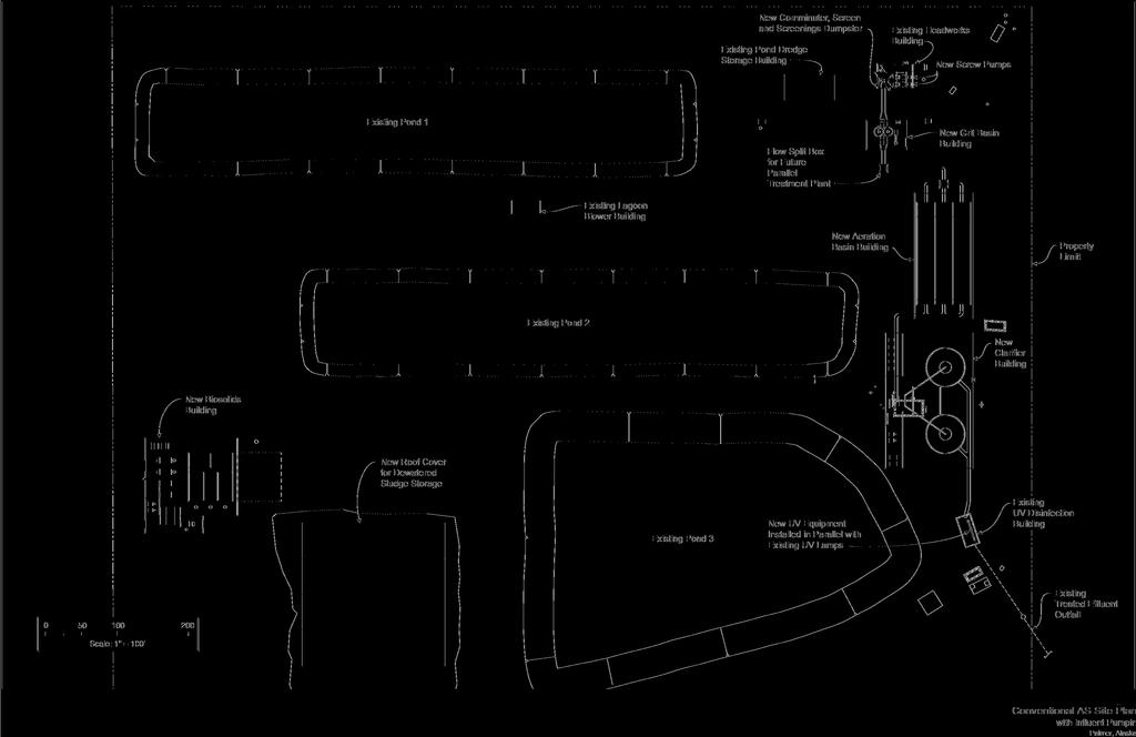
3 Figure 14


4 Conventional AS Site Plan without Influent Pumping
5 6.2 Alternative 2: Integrated Fixed-Film Activated Sludge Description The Integrated Fixed-Film Activated Sludge (IFAS) is an activated sludge process that combines both dispersed growth biomass and fixed film biomass in the same aerobic reactor basin. The combination of both types of biomass is termed integrated fixed-film activated sludge, or IFAS. The system combines an attached growth (fixed film) process with activated sludge technology to provide nutrient removal and a relatively efficient treatment process. It produces higher quality effluent relative to a conventional activated sludge process operating alone without a fixed film biomass component. The IFAS system typically uses synthetic materials or media suspended in, or fixed in the aeration basins. Biofilms form on the surface of the media thus providing greater biomass concentration than would be available with a dispersed growth activated sludge system only. The fixed film biomass enables the system to operate with smaller process basins and improved settling sludge in the secondary clarifiers. The IFAS-system when compared to CAS, supports higher wastewater treatment loadings for equivalent sized biological process basins, can improve biological process stability, and therefore produce consistently higher effluent quality over the CAS process. Grit removal equipment is recommended for this option as described in Section 6.01, Fine Screening and Grit Removal. Figure 16 depicts the IFAS system. Mixing of the anoxic basins is provided by tank mixers, and aeration of the mixed media basins is provided by tank bottom mounted diffusers. As noted earlier for the conventional activated sludge alternative, inclusion of the anoxic basins allows for energy savings on aeration operation. The Attached Growth Airlift Reactor (AGAR ) is one manufacturer s version of the IFAS system. The AGAR IFAS system uses cylindrically shaped plastic media as suspended biomass carriers combined with activated sludge for biological treatment and nutrient removal. Two-stage, in series mixed media basins are preceded by an anoxic basin. Aeration is provided to the mixed media basins with coarse bubble diffusers providing complete mix of the mixed media contents and enhancing aeration efficiency. Biomass fixed to the integrated media continually grows and sloughs off. The open design of the media, as well as rigorous basin mixing maintains an optimal fixed biomass, avoiding media clogging. The mixed liquor and fixed biomass in the aerated basins provide a large concentration of biomass relative to other activated sludge processes and thus solids retention time (SRT) increases in a smaller volume better suited for nitrification. The aerated basins are provided with screens which retain media within the 44
6 basin and allow mixed liquor passing to the secondary clarifiers. Screens remain free of foulants due to a combination of media and air scour Preliminary Design Criteria Per Figure 16, wastewater that has received preliminary treatment (screenings and grit removal) is delivered into the anoxic/aerated-integrated media basins for secondary treatment. Treated effluent from the anoxic/aerated-integrated media basins flows through secondary clarifiers, and then to a UV disinfection system prior to final disposal. Sludge from the clarifiers is recycled to the head of the anoxic basins as return activated sludge. Waste sludge produced during treatment is pumped periodically from the secondary clarifiers to a solids handling system. This handling system is described in detail in Section 6.8, Waste Solids Management. Table 11 summarizes the selected preliminary design data for an IFAS system to treat the design average daily flow. IFAS equipment suppliers include Siemens AGAR IFAS and AnoxKladnes, Inc. HYBAS. A HYBAS equipment submittal is included in Appendix C. 45
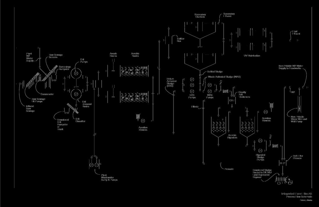
7 Figure 16
8 Table 11: Selected Preliminary Design Parameters - IFAS Parameter Values for 2.0 MGD ADF Number of Anoxic and Aerobic Basins, each 2 Total Volume of Anoxic Basins, gallons 67,000 Individual Anoxic Basin Dimensions, feet Width = 20 Length = 14 Height = 18 Total Volume of Aerated Basins, gallons 330,000 Individual Aerated Basin Dimensions, feet Width = 20 Length = 70 Height = 18 Stages per Aerated Basin 2 Basin Water Depth, feet 16 Hydraulic Retention Time, hours ~ 5 Media, m 3 (ft 3 ) 1,019 (35,986) Media Fill Ratio, % 50 Mixed Liquor Suspended Solids, mg/l 3,500 Return Activated Sludge Ratio, % 100 Total Aeration Demand, scfm ~ 5,066 Sludge Yield, lb/lb 0.54 Number of Secondary Clarifiers 2 Secondary Clarifier Dimensions, feet Diameter = 55 Height = Environmental Impact A summary of the impacts of developing the IFAS alternative for the City is similar to the impacts of the conventional activated sludge option presented previously Land Requirements As shown in Figures 17 and 18, the development of the IFAS alternative can be staged at the site of the City s existing wastewater treatment facility. Figure 17 illustrates the site development using the existing headworks pumping station. Figure 18 shows the site 47
9 developed with using only gravity flow through the process. As with the CAS option, this latter configuration would require excavation of the new treatment area so as to maintain the hydraulic grade line of the existing influent gravity sewer system delivering wastewater to the treatment facility Cost Estimates Rough order of magnitude, pre-design estimates of construction and operation and maintenance (O&M) costs in year 2007 dollars are summarized in Table 17 later in this report. Costs are based on continued influent pumping at the headworks. Details of the quantities, components, and unit costs used to develop these costs are included in Appendix A of this report Advantages/Disadvantages The following paragraphs address the advantages and disadvantages of the IFAS treatment process. The IFAS treatment alternative has the following advantages: 1. The total concentration of biomass in the system is higher per unit volume of bioreactor basin than with conventional dispersed growth activated sludge systems. This makes the size of the system smaller relative to conventional activated sludge systems reducing both capital and operating costs. 2. The system can be configured to produce a nitrified effluent to meet the City s current effluent discharge permit. 3. Fixed film biomass typically has better gravity settling characteristics than does dispersed growth biomass. The IFAS treatment alternative has the following disadvantages: 1. IFAS is relatively new to the US. As a result, there is not a large amount of operating experience with the process in this country. 2. Gravity clarification is required to separate solids from treated effluent. 48