of abt. $ 60 million on annual basis. The $ 60 million would then be used to cover salary and maintenance, which is estimated to be around $ 10
|
|
|
- Julian Gibson
- 5 years ago
- Views:
Transcription
1
2 SUMMARY The invention relates to cost efficient ways to lift seawater to extreme heights, with the intention to produce electricity. To do so, we will use pressure 1200 meters below the seabed and introduce compressed air. When we introduce air at these extreme depths through air compressors, the seawater has no other option to go upwards in the tube. The submerged pipe will have a narrow section in the middle of the pipe, thus causing a venturi effect which expands the compressed air and lowering the density of the water-air mixture. A proper designed venturi will increase the pump throughput and minimize the air consumption. Speed of the air also have significant impact on the density, and these factors need to be carefully balanced. Together with the defined 1/40 venturi design and a suction line of 1200 meters, each air compressor is capable of delivering 1000 liter of water per second. If the power plant is operated 12 hours a day, the annual electricity consumption would be approximately 6.6 GWh. Our intention is to utilize the water by running it through a minimum of two water turbines. A total of 37 air compressors and 37 pipes will be used to provide the water turbines with 131 mill liters of water per hour 12 hours a day. Based on these parameters the annual output is estimated to be approximately 613 GWh by using francis turbines. In economic terms, the annual cost for purchasing electricity through the onshore grid is estimated to be $ 17 million. The income for producing electricity is estimated to be $ 77 million, giving a net profit
3 of abt. $ 60 million on annual basis. The $ 60 million would then be used to cover salary and maintenance, which is estimated to be around $ 10 million on annual basis. The overall EBITA would then be approximately $ 50 million, which make this invention one of the best in this century. Not only will this invention solve the global energy crises, it will also solve the pollution problem we have with coal, nuclear and other fossil, if the politicians introduce high tax for all energy that pollute.
4 DESCRIPTION 1. SYSTEM THAT PRODUCES ELECTRICITY OFFSHORE THROUGH A FIXED INSTALLATION (Figur 1), INCLUDING A MINIMUM OF TWO WATER TURBINES AND TWO GENERATORS (Figur 2), ONE HIGH WOLTAGE DUAL PURPOSE SEACABLE OPERATED BY A CONTROL CENTRE ONSHORE (Figur 3), AND TUBES PLACED UNDER THE SEABED TO OBTAIN A MINIMUM PRESSURE OF 120 BARS (Figur 4), WHERE WATER IS PUSHED UPWARDS BY TURNING ON THE AIR COMPRESSORS (Figur 5). WHEREOF THE SYSTEM IS CHARACTERIZED WITH: - OPERATION WILL BE DONE BY PURCHASING ELECTRICITY FROM THE ONSHORE GRID THROUGH A DUAL PURPOSE SUBSEA CABLE, - THE ONSHORE CONTROL CENTRE OPERATE THE AIR COMPRESSORS TO PUSH WATER UPWARDS IN ADDITION TO MONITOR THE TURBINES, - WHEROF ALL ELECTRICITY GENERATED THROUGH THE WATER TURBINES AND GENERATORS ARE TRANSPORTED TO THE ONSHORE GRID THROUGH A HIGH WOLTAGE SUBSEA CABLE. The invention relates to cost efficient ways to lift seawater to extreme heights, with the intention to produce electricity. To do so, we will use pressure 1200 meters below the seabed and introduce compressed air. When we introduce air at these extreme depths through air compressors, the seawater has no other option to go upwards in the tube, as illustrated in Figure 5. However, there is a limitation of how high the water actually can go, and the breaking point is 400 meter if we use large size air compressors with about 2000 horse powers. Enclosed to this patent application you find extensive excel calculations that confirm the breaking point at 400 meter. It is however possible to go higher, but in that case we need much more pressure than 120 BARS, when the aim is to reduce operational costs on electricity.
5 The working principle is to inject compressed air into a vertical water pipe to lower the density. The outside density is then causing a static pressure which pushes in-pipe water- air mixture upwards. Illustration above show how air push water upwards due to usage of pressure below the water surface The air compressor needs to be submerged to enable the outside water to push upwards. A deeper submerged pipe will increase this driving force, but also requires a higher discharge pressure for the air compressor. This project has concluded that submerging the tube riser to 1200 m depth is optimal. By going this deep, we utilize the extreme pressure below sea, which then again reduces the electricity need for the compressor. Although our model expressly state that the optimal solution would be to utilize pressure 1200 meters below the seabed, our patent claim is to use air compressors in a combination with pressure below the water surface, when the aim is to generate electricity through water turbines and generators. No underwater pumps will be used, which is standard
6 equipment for onshore pump installations, or so called pumpekraftverk. The main reason for this is to reduce the electricity bill for the pumps, as air compressors uses 100 times less electricity than water pumps. In addition, the maintenance cost are much less for the air compressors. The submerged pipe will have a narrow section in the middle of the pipe, thus causing a venturi effect which expands the compressed air and lowering the density of the water-air mixture. A proper designed venturi will increase the pump throughput and minimize the air consumption. Speed of the air also have significant impact on the density, and these factors need to be carefully balanced. Illustration above (from the isometric drawings) gives the optimal dimensions for the venturi The venturi is a vital part for getting the electricity bill down, hence we have used years of studies to optimize the design. The key results are given by our feasibility study and reported in the table below:

7 For the results in the below table the following parameters were fixed: 1000 liter/s sea water flow Pump suction point located 1200m below sea level. Air injected at 1200m below sea level Water/air discharge 400m above sea level. Venturi size 30 cm Diameter 40 cm Diameter 50 cm Diameter Length (m) Air Discharge 120 bar (m3/s) Electricity (MW) Air Discharge 120 bar (m3/s) Electricity (MW) Air Discharge 120 bar (m3/s) Electricity (MW) 1 0,013 1,5 0,013 1,5 0,013 1,5 5 0,016 1,9 0,016 1,9 0,016 1,9 20 0,029 3,4 0,026 3,0 0,025 2,9 As concluded in the table below, it would be optimal to choose a venturi that is 1 meter long and 40 centimeter in diameter, if the aim is to use as little electricity as possible. By choosing a venturi that is 20 meter long instead of 1 meter, the electricity usage would double, from 1.5 MW per hour to 3 MW per hour. Table above gives the optimal lenght for the venturi in our system, which is 1/40 design
8 Together with the defined 1/40 venturi design, each air compressor is capable of delivering 1000 liter/s of water with 1.5 MW hr of electricity usage, under the condition that we utilize a pressure of 120 BARS below sea. Further explanation and model testing is to be found in the enclosed excel sheet (doc.nr TECH 02). The model in the excel sheet is based on the PipeSize excelspreadsheet from At 1.6 megawatt per hour, the following air compressor delivered by K. Lund Offshore ( offshore.no/air compressors/) is capable of delivering 1025 liter of water per second to the storage with a dynamic pressure of 120 BAR: The air compressor is standard equipment and consist of: 1 centrifugal compressor + 1 displacement booster 1 oil free screw compressor + 1 displacement booster 2 oil free screw compressors + 1 displacement booster Based on several pilot tests the last 10 years and extensive modelling, the optimal design is to locate the suction line 1200 meter below water to have enough driving forces, ref Figure 4. Compressed air will be injected at the lower end of this suction line, as illustrated in Figure 5. Both the suction and discharge line should be 60 cm in diameter to minimize friction losses. Piping isomtectric drawings have been produced and ready for order at a vendor. Due to the corrosive nature of the sea water and air, a plastic material should be selected for the pipe. The best option is a PVC-material. PVC has a very low surface roughness compared to traditional stainless steel. This will limit the friction losses and consumption of compressed air.
9 At the suction inlet a screener and a non return valve will be installed, as outlined in Figure 5 and attached isometric drawings. The inlet screener will filter out particles, fish and algea. The non return valve acts as a preventive measure to force the air water upwards during operations. Further details of the non return valve and inlet sceener is to be found in the isometric drawings. Our intention is to utilize the water by running it through a minimum of two water turbines. A total of 37 air compressors and 37 pipes will be used to provide the water turbines with 131 mill liters of water per hour 12 hours a day. The number 131 million liter of water have been given by the francis turbine vendor, which then again gives us an electricity output of approximately 613 GWh on annual basis. Figure 2 represent the equipment needed to be purchase, and this is standard equipment that can be purchased by any francis turbine vendor. Generation of electricity will be done 12 hours a day, as electricity prices only peak during day time. In this respect, we have a good window to complete any required maintenance during night, as the hydroelectric power plant shuts down for about 12 hours. The invention can not be categorized as storage of power, as the electricity generated through the water turbines and generators will immediately be shipped to the onshore grid through a subsea cable. Alternatively, the subsea cable may be connected to an offshore hub, which then again transport the electricity to the onshore grid. As fresh food, high voltage electricity is a commodity that only can be consumed immediately, until high voltage batteries are invented.
10 The hydroelectric offshore installation consist of a steel construction, which neither is a new invention. The installation could either be a steel jacket or a cylindrical hull. Concrete would also be an option to extend the lifetime of the installation, as you find in the North Sea of Norway. Figure 1 show an example of a 400 meter steel jacket that comply with the length we want to achieve. Gulf Marine Fabricators in Houston Texas have extensive experience in producing 500 meter tall jacket, which would be the preferable yard to place an purchase order. All water moving upwards will immediately flush down the pipes and hit the turbine blades. It is preferable to use francis turbines although this is not a requirement for the power plant to work. In other words, we seek patent protection to use whatever turbine that is possible to buy in the open market. To keep the required pressure for the turbines air valves will be installed on top of the installation. As fast moving liquid increase in temperature, the air valves will also have a function to reduce the water vapor or steam. Turning on and off the air compressors will be handled by a single remote computer that is connected to the internet, as referred to Figure 3. Power to operate the air compressor will be provided through a dual purpose subsea cable. Control and monitor system for generating electricity through the water turbines will also be done remotely, which is standard procedure for onshore power plants. In this respect, the offshore installation will be un-manned and HSE risk is close to zero.

11 Figure 1

12 Figur 2

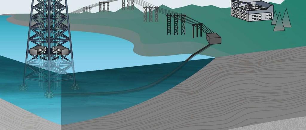
13 Figur 3

14 Figur 4
15 Figur 5