Design Windows and Roadmaps for Laser Fusion Reactors
|
|
|
- Thomasina Clarissa Johnston
- 5 years ago
- Views:
Transcription
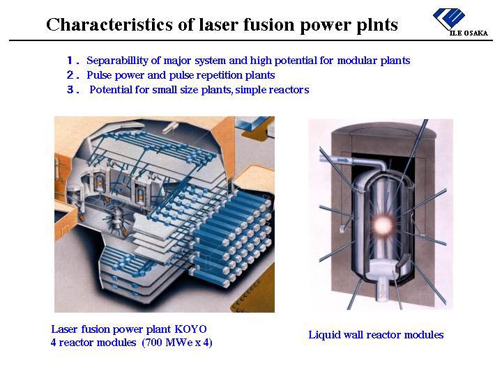
1 US/Japan Workshop on Power Plant Studies April 6-7, 2002, San Diego Design Windows and Roadmaps for Laser Fusion Reactors Yasuji Kozaki Institute of Laser Engineering, Osaka University Outline 1. Design windows for attractive laser fusion reactor 2. Critical issues 3. Roadmaps
2 INTRODUCTION - Based on the recent progress of implosion physics and diode pumped solid-state laser, KOYO design study has been carried out as a joint project of universities, industries, and international collaborations. - Following the KOYO design study Systems Analysis of laser fusion program has been conducted by the Committee on Laser Fusion Research Strategy (chair Y. Kozaki) organized in the ICF Forum. - A network analysis technique PERT and GERT (Graphical Evaluation and Review Technique), which was applied for TOKAMAK program by Sekiguchi committee organized by Institute for Future Technology in 1983 has been applied for evaluating the IFE research program in a similar way. - We are now investigating the roadmaps of a laser fusion research program and new reactor concepts with considering the recent progress of the fast ignition physics, under the Committee on Laser Fusion Roadmap (chair K.Tomabechi, vicechair Y.Kozaki) organized in the IFE Forum.
3
4
5 Gain curves for central spark and fast ignition 500 Target Gain Fast ignition corn target two design points KOYO fast ignitor optimistic : G=300(E L / 1 ) 1/3 fast ignitor conservative : G=150 (E L / 1 ) 1/3 central spark optimistic : E L MJ G=150 (E L / 4 ) 1/3 (KOYO gain curve) central spark conservative : G=100 (E L / 4 ) 1/3 - Target gain G can be given by simple functions of E L 1/3 in high gain region. -Because maximum burning fusion power is proportional to radius of pellet, while fuel heating energy E L is proportional to volume of pellet.
6 COE of single and multi module plants with r c constraints COE Yen / kwh MWe x 1 rc > 20 Hz 5 < rc < 10 Hz 10 < rc < 20 Hz rc < 5Hz 1200 MWe x 1 COE Yen / kwh rc reactor pulse rep-rate rc >10 Hz 3 < rc < 5 Hz rc < 3 Hz 5 < rc <10 Hz 400 MWe x MWe x MWe x E L MJ E L MJ Fig. (1) COE of single reactor plants Fig.2(2) COE of 4 module plants - Multi reactor module plants can be optimized in rather low rc (reactor pulse rep- rate), 3~5Hz. - While single reactor module plants are optimized in higher rep-rate, 10~20Hz. (Gain curve: central spark conservative case, LD unit cost: 3.1Yen/W )
7 COE Sensitivity to Target Gain Curve MWe Plants MWe 4 module Plants fast ignition central spark fast ignition central spark LWR1200MWe E L MJ E L MJ Fig.1(1) COE of 1200 MWe Plants Fig.1(2) COE of 4 x 600 MWe Plants Gain Curves Central Spark upper line : G = 100 ( E L MJ / 4 ) 1/3 lower line : G = 150 ( E L MJ / 4 ) 1/3 Fast Ignition upper line : G = 150 ( E L MJ / 1 ) 1/3 lower line : G = 300 ( E L MJ / 1 ) 1/3 LD Cost : 3.1 yens / W
8 COE Sensitivity to Laser Cost MWe Plants central spark LD high CO2 eliminated oil power plants 600 MWe 4 module plants fast ignition LWR 1200 MWe LD low LD high LD low conventional power plants fast ignition central spark LD high LD low E L MJ E L MJ Fig.2(3) COE of 1200 MWe plants Fig.2(4) COE of 600 MWe x 4 plants LD Cost : 3.1~6.2 yens / W, Gain curves are conservative cases : Central Spark G=100 (E L MJ/4) 1/3 ; Fast Ignition G=200 (E L MJ/1) 1/3 - LD unit cost of 3 yens / W is required to compete with conventional power plants in central spark modular plants, and even if LD cost of more than 6 yens / W can compete with the fossil fuel power plants with CO2 eliminated.
9 Table Design windows of laser fusion modular plants, pulse energies, pulse rep-rates, and output power Laser energy MJ Target gain Fusion pulse energy MJ Pulse rep-rates reactor(laser) Net output power MWe 1 reactor modular plant Fast ignition 0.2 (ignitor 0.1) 0.4 (ignitor 0.1) (24) mini size small size plant MWe 0.8 (ignitor 0.1) 250 KOYO Fast (15) MWe Central spark (15) ~ 150 (KOYO) 400 ~ 600 ~3 ( 6) ~ MWe MWe
10 Table 2 Key design parameters, constraints, and critical issues Key design parameters Design windows Design constraints and issues Target gain central spark concepts -beam number ~90 G 100~150 at 1~4 MJ -irradiation nonuniformity ~0.3 % fast ignition concepts -required ignitor laser energy ~100 kj 100~300 at 0.2~1 MJ -ignitor timing and focusing (~50 ps, ~50 µm) Fusion pulse energy central spark concepts -first wall protection 100~600 MJ -for liquid wall: ablation and evacuation Ef =G E L fast ignition concepts -for solid wall: charged particles intensities 20~300 MJ Reactor pulse rep-rate liquid wall concepts -evacuation time <300 ms (conditions for laser r C 3~10 Hz beam propagation and pellet injection) dry wall concepts -chamber radius R< 5~10 3~20 Hz -beam propagation in high Z gas Reactor thermal power -adequate reactor power size Pct = r C Ef M 100~4000 MWth -neutron wall loading, chamber radius -final optics damage and maintenance Laser energy E L 0.5~4 MJ -laser cost (especially laser diode cost) laser efficiency η D 8~12 % (DPSSL) -product of efficiency of many components laser pulse rep-rate r L 3~30 Hz -cooling medium, thermal effect compensation -life time of key laser components Reactor module number n 1~10 -beam switching -layout of laser beam and final optics
 = 6 mm M(corn) = 40 mg Pb 240 MJ DT target without corn 240 MJ corn target Corn Target")
11 Corn target size and mass - considering protection of chamber wall and optics - r = 2 mm M(fuel) = 2 mg r (corn) = 6 mm M(corn) = 40 mg Pb 240 MJ DT target without corn 240 MJ corn target Corn Target Experiment
12 Requirements for IFE chambers (1) ILEOSAKA What factors give the economically attractive laser fusion power plants? - Target gain and laser energy (gain scaling) >> Fusion pulse energy - Pulse repetition rate >>Fusion output power - Neutron loading on the first wall and the final optics >> Laser energy (cost) >> The size of chamber and reactor building (Lifetime of material) - Intensity of X-rays and charged particles on the first wall and the final optics (Limiting factors of reactor size and rep-rate, or not?)
13 Requirements for IFE chambers (2) ILE OSAKA Results of economic analysis on laser fusion plants - The sensitivity analysis on LD cost show that even if in the case of central spark concept (conservative target gain curve), the broad design windows of attractive power plants can be obtained in modular plants. - When fast ignition can be achieved, the required laser energy is so small that very attractive fusion power plants can be achieved. But in the case of small laser energy and small fusion pulse energy, the design windows are strictly restricted by the rep-rates of laser pulse and/or reactor pulse. - In modular power plants the requirement for reactor pulse rep-rates is mitigated, but laser rep-rate and beam sharing control may be critical issues for lower COE.
14 Issues and major subjects on liquid wall chamber ILE OSAKA X-rays, charged particles Energies Energy absorption Liquid surface ablation Fusion burning output estimation ILESTA, MEDUS X-rays ~ 30 kev Charged particles 0.1keV ~ 1MeV Ablation model with plasma absorption by abrated plasma Free surface liquid flow cooling Evacuation of metal vapor DSMC code, Tsunami code Required vacuum level <10-2 ~10-4 Torr Nonlinear effect on laser beam Impact on pellet injection Estimating rep-rate >3 ~ 10 Hz
15 Results of evacuation simulation with DSMC code and TSUNAMI code in different boundary conditions DSMC 1 DSMC 2 TSUNAMI 1 TSUNAMI 2 ILE OSAKA DSMC 1 DSMC code with condensation ratio is 0.98 pressure [torr] DSMC 2 DSMC code with condensation ratio is 0.92 TSUNAMI 1 TSUNAMI code without viscosity TSUNAMI 2 TSUNAMI code with viscosity (8.77 x10⁻⁵ pa*s) using the value of Hg of 873 K and 1 atm time [s] The results of DSMC code and TSUNAMI code with different conditions. The differences of results with different condensation ratio and viscosity are not so large as those with surface temperature.
16 Ion spectra of fusion output (400 MJ target) ILE OSAKA C T D H alpha X-rays energy MJ 4 average energies 30 kev % 1.0 particle number 10 x alpha particles charged particles MeV C: 1 MeV H,D,T: 200 kev particle energy [MeV] neutrons fusion output 328 MJ 14.7 MeV MJ spectrum of fusion ions (400 MJ direct irradiation targets) - X ray spectrum is much harder than indirect target - particles and fast ions energy are 1-4 MeV
17 Pulse heat loads on chamber walls (400 MJ target case) ILE OSAKA intensity[w/cm2] X-ray (r=2m) X-ray (r=4m) X-ray (r=8m) alpha particles (r=2m) alpha particles (r=4m) alpha particles (r=8m) charged particles (r=2m) charged particles (r=4m) charged particles (r=8m) X-ray peak W/cm 2 alpha peak 10 8 W/cm 2 Ions peake 10 8 W/cm 2 alpha pulse width µsec Ions pulse width µsec r=2m r=4m r=8m time [µsec] Thermal pulse power on first wall Total pulse load J /cm 2 Average power 3Hz,W/cm Neutron load (400MJ targets) radius 2m, 4m, 8m Hz, MW/m
18 Ablated depth and mass of liquid wall (400 MJ case) evaporation depth [micron] r=2m r=4m r=8m CHAMBER RADIUS 2m 4m 8m FLUENCE 144 J/cm 2 36 J/cm 2 9 J/cm 2 ABLATION DEPTH 7.8 micron 2.3 micron 1.1 micron ILE OSAKA ABLATION MASS 4.4 kg 5.2 kg 10.0 kg time [ sec ] In the case of 2m chamber radius, the ablation depth is almost equal to the renge of alpha particles, as the energy deposit with alpha particles is enough to ablate the mass of this depth. When the radius is larger than 3m, the ablation depth increases softly with increasing fluence of charged particles, as the over 90 % of charged particles energy is absorbed with ablated liquid metal plasma.
19 Pulse heat loads on chamber walls (20 MJ, 100 MJ case) ILE OSAKA intensity [ W / cm2 ] X-ray (r=4m 100MJ) X-ray (r=8m 100MJ) X-ray (r=4m 20MJ) alpha particles (r=4m 100MJ) alpha particles (r=8m 100MJ) alpha particles (r=4m 20MJ) charged particles (r=4m 100MJ) charged particles (r=8m 100MJ) charged particles (r=4m 20MJ) Laser energy kj Gain X-ray peak W/cm 2 α peak 10 8 W/cm 2 Ions peak 10 8 W/cm 2 20 MJ r=4m MJ r=4m MJ r=8m Total load J /cm time [µsec] Thermal pulse power on first wall ( 20 MJ targets) radius 2m, 4m, 8m Average power 10Hz,W/cm 2 Neutron load 10Hz, MW/m
20 Energy density and temperature profile of dry wall ILE OSAKA temperature [ K ] r=4m 20MJ r=8m 100MJ W melting temp. temperature [ K ] r= 4m, 20 MJ t= µsec t= µsec t= µsec t= µsec r= 8m, 100 MJ t= µsec t= µsec t= 2.087µsec t= µsec cooling temperature time [ µ sec ] depth [ µm] The peak surface temperature are about 2700K (r=4m, 20MJ case, at t=1.062µsec), and 2500K (r=8m, 100MJ case, at t=2.087µsec) At ending of charged particles pulse, the surface temperatures are about 1700K in both cases.
21 Chamber sizes of dry wall and liquid wall for same output ILE OSAKA Thermal load 1.6 J/cm 2 Neutron load 0.7 MW /cm 2 Thermal load 32 J/cm 2 Neutron load 2.8 MW /cm 2 10m (r=4m) 6m (r=2m) Dry wall 80MWe 20MJ pulse x 10Hz Liquid wall 80MWe 100MJ pulse x 2Hz Dry wall chamber : for smaller purse energy and higher rep-rates Liquid wall chamber : for larger purse energy and smaller radius chamber
22 What factors give plant sizes? - Fast ignition target design :Target gain 250 with laser energy 800 kj Fusion pulse energy 200 MJ - Optimum plant output power 60 MJ with laser energy 400 kj Scale merits : the 2/3 power law(such as fission plants) 1200 ~ 1500 MWe ( ~ 2400 MWe in modular plants) Small size merits: flexibility of construction and fitting in demand : assembling in factory and small indirect cost - Especially in laser fusion plants, Decreasing neutron flux on final optics >> Small size of reactor buildings Modular plants with multi small reactors and a high rep-rates laser can give the deign flexibility.
23 80m 1200 MWe Reactor Plant and Building 300 MWe x 4 Reactors Plant and Buildings (Beam layout is a critical issue)
24 Critical Issues and Major Tasks Physics issues and major tasks (2002~2015) - Fast ignition physics establishment and demonstration of ignition and burning (PW project, and FIREX) - Hydro dynamic equivalent experiment of high gain target (EPOC: high uniformity ~50kJ laser facility) Driver issues and major tasks (~2012) - High repetition high power laser (100J and 1kJ DPSSL module, and excimer laser module development) - LD cost down technologies - Long-lifetime-laser-material development Pellet technologies issues and major tasks (~2012) - Cryo-target fabrication and corn target technologies - Pellet injection, tracking, and shooting technologies Reactor technologies issues and major tasks (~2012) - Chamber wall protection technologies (for FIREX, and the high rep-rate burning experiment) - Liquid wall chamber feasibility studies, simulation on liquid wall ablation, evacuation, and free liquid surface control - Reactor structural material and final optics (pulse irradiation with charged particles and neutrons) - Consistent reactor design (developing new power plant concepts and establishing a experiment reactor design)
25 Milestones Table Milestones and major facility specks on a laser fusion roadmap Establishment of Steady burning experiment Demonstration of plasma physics power generation Facility FIREX IFER DEMO Commercial plants Purpose, Conditions for starting and selection Laser energies Demonstration of ignition and burning - 1st stage: Driven burning physics (Break even Q~1) Second stage: ignition and burning (α heating physics Q~10) - High density implosion (already demonstrated) - Short pulse laser heating physics (scaling for kev level heating) - Ultra high intensity laser technologies (already developed) ~ 80 kj implosion 50+ heating ~30 Integrated test of burning technologies - High gain, and high rep-rate fusion burning - High rep-rate laser - Reactor chamber test, tritium breeding blancket, material test, etc. - Steady fusion output with fast ignition (Although evaluating the results of central spark concepts with US NIF, EPOC.) - Selection of driver based on module development - Selecting the chamber concepts (liquid wall and/or solid wall) 200 kj implosion 100+ heating 100 Integrated test of prototype power plant - Demonstrate of relliable power generation (facility performance, lifetime) - safety, and prospect for COE - Selecting the optimum target irradiation methods, and drivers - Lliquid metal cooling and/or gas cooling (considering multi chambers test) - Technologies scalable to commercial plants by multi module and scale up Goal Economically and environmentally attractive plants - COE (6~10 Yen/ kwh ) - Modular plants for using the characteristics of laser fusion - Flexibility of construction and operation 400 ~ 800 kj 400 ~ 800 kj Target Gain ~ ~ ~ 250 Fusion pulse energies ~ 1 MJ 20 MJ 100 ~ 200 MJ 100 ~ 200 MJ Pulse rep-rate 1 shot / hour ~ 1 Hz ~ 3 Hz 3 Hz (5~10) Fusion output power - 20 MWth 120 ~ 240 MWe 1200 MWe Laser efficiency 1 % 6 ~ 8 % 10 % 10 % Construction cost 22 ~ 40 BYen 100 ~ 200 BYen 200 ~ 300 BYen ~ 360 BYen
26 Road maps for laser fusion reactors Fast Ignition experiment (FIREX) National Ignition Facility (NIF) IFER Design Integrated reactor technology test Implosion laser Fusion pulse 20MJ, 20 MW 100 kj, ~1Hz Ignitor ~100 kj High repetition laser R&D Advanced laser R&D Pellet fabrication, injection Fusion pulse 200 MJ, 3 Hz Net output power ~200 MWe Reactor chamber technology Fusion reactor technology (Blanket technology, Tritium technology, reactor structural material, reactor design, safety etc.) Steady burning experiment DEMO Power generation
27 FIREX II Target Chamber System ILE Osaka Ignition Beam λ = 1053 (527) nm 4 beams 10 kj/2 10 ps F/5, 100 cm φ Implosion Beams λ = 351 nm 92 beams 50 kj/3 ns F/8, 15 cm φ 5 m
28 The basic design guidelines for KOYO - Fast 1) Target: Fast ignition target with corn - laser energy 800 kj, fusion gain 250, fusion pulse energy 200 MJ - Reactor pulse rep-rate 3 Hz, 600 MWth - Blanket energy multiplication 1.1, reactor thermal output 660 MWth - Energy conversion efficiency 43% - Reactor electric output 284 MWe, and auxiliary electric power 6% - Laser recirculating power 24 MW (8.94%), laser efficiency 10% DPSSL case - Net electric power of one reactor module 240 MWe, and 5 reactors modular plant 1200 MWe 2) Laser: DPSSL implosion 700kJ, ignitor 100 kj (option excimer laser) - efficiency 10% - rep-rates 15 Hz - laser gain medium HAP4, or Nd-YAG ceramics 3) Chamber: Liquid fast flow covering first wall with thin liquid layer - Pb - rep-rates ~3 Hz 4) Final optics: Fused silica optical wedge for implosion lasers (unsettled yet for ignitor) [Options] - Small DT fuel target (laser energy 400 kj, fusion gain 150) for solid wall chambers - Advanced-fuel-corn-target with magnetic wall protection and direct energy conversion
29 Summary - Analysis of design windows shows that even with the conservative target gain scaling, the broad design spaces for attractive power plants can be obtained in modular plants, although costs and lifetimes of lasers are critical issues. - Fast ignition offers opportunities for smaller size plants with smaller laser energy, then give high potential for competitive COE. - We identified critical issues which should be achieved for fast ignition targets, high rep-rates lasers, pulse energy protection chambers, etc. - Results of network analysis shows that laser fusion programs have much flexibility and could promote with small size facilities and a rather small cost. Especially in fast Ignition case, we could establish physics base of ignition and burning with small size facility, and achieve reactor technologies with a small size steady operation reactor. - For achieving fusion energy goals we have various options which are based on common fusion reactor technologies. Laser fusion options offer some good candidates, which also could be achieved by strong supporting with fusion reactor technologies development.