1. About this edition of the operating manual
|
|
|
- Hubert Black
- 5 years ago
- Views:
Transcription


1
2 Contents 1. About this edition of the operating manual Safety precautions General information Getting started Operation Specifications Maintenance Warranty and claims EU Declaration of conformity About this edition of the operating manual The manual applies to following models and versions of personal vortexes for tubes and microtubes: V-1 plus version V.3AW V-32 version V.1AW 2
3 2. Safety precautions The following symbols mean: Caution! Make sure you have fully read and understood the present Manual before using the equipment. Please pay special attention to sections marked by this symbol. GENERAL SAFETY Use only as specified in the Operating manual provided. Do not use the unit if dropped or damaged. Store and transport the unit in a horizontal position (see package label) at ambient temperatures between -20 C and +60 C and maximum relative humidity of 80%. After transport or storage in humid conditions and before connecting to electric circuit, keep the unit under room temperature for 2-3 hrs. Before using any cleaning or decontamination methods except those recommended by the manufacturer, check with the manufacturer that the proposed method will not damage the equipment. Do not make modifications to the design of the unit. ELECTRICAL SAFETY Connect only to a power supply with voltage corresponding to that on the serial number label. Use only the external power supply unit provided with this product. Ensure that the power switch and the external power supply connector are easily accessible during use. Disconnect the unit from the electric circuit before moving. Turn off the unit by disconnecting the external power supply from the power socket. If liquid penetrates into the unit, disconnect it from the external power supply unit and have it checked by a repair and maintenance technician. Do not operate the unit in premises where condensation can form. Operating conditions of the unit are defined in the Specifications section. DURING OPERATION Do not impede the platform motion. Do not operate the unit in environments with aggressive or explosive chemical mixtures. Please contact manufacturer for possible operation of the unit in specific atmospheres. Do not operate the unit if it is faulty or has been installed incorrectly. Do not use outside laboratory rooms. Do not place a load exceeding the maximum load value mentioned in the Specifications section of this Manual. BIOLOGICAL SAFETY It is the user s responsibility to carry out appropriate decontamination if hazardous material is spilt on or penetrates into the equipment. 3
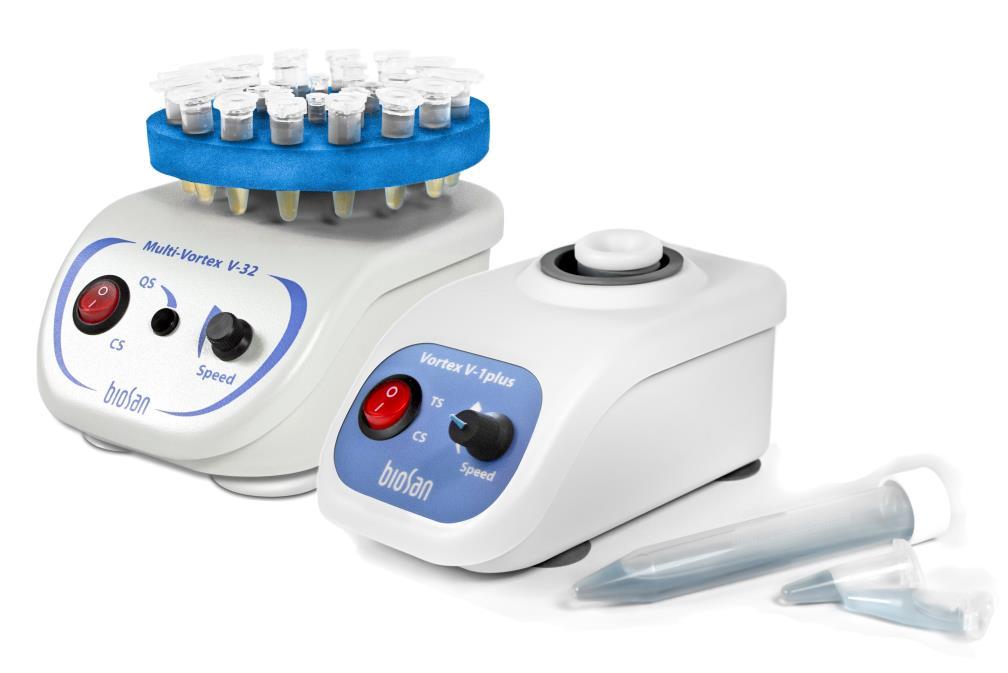
4 3. General information V-1 plus / V-32 vortex is intended for intensive mixing of samples in tubes using an eccentric mechanism. Vortex is applicable in all the fields of laboratory research in biotechnology, microbiology and medicine: - Mixing tissue samples; - Suspending cell samples; - Mixing chemical samples; - Mixing bacterial and yeast cells when washing from the culture medium - Extracting metabolites and enzymes from cells and cell cultures, etc. - Vortexing during various operations with DNA/RNA. Vortex has two operation modes: - continuous operation; - impulse operation. Model V-1 plus is a personal vortex with fluoroplastic head for single tube ( ml) vortexing. Model V-32 is a universal vortex multipurpose device with different accessories. It is supplied with a 32-socket universal platform PV-32 for Eppendorf type tubes up to 15 ml (1.5/0.5/0.2 ml - 16/8/8 sockets) and a PL-1 head for vortexing a single tube up to 50 ml. An optional 6-socket platform PV-6/10 for 10 ml tubes (maximum tube diameter 15 mm) or a platform PV-48 for 6 strips of 8x0.2 ml microtubes can be supplied on request. 4


5 4. Getting started 4.1. Unpacking. Remove packing materials carefully and retain them for future shipment or storage of the unit. Examine the unit carefully for any damage incurred during transit. The warranty does not cover in-transit damage. Warranty covers only the units transported in the original package Complete set. Package contents: V-1 plus - V-1 plus, personal vortex... 1 pce. - External power supply... 1 pce. - Operating manual, certificate... 1 copy V-32 - V-32, multi-vortex... 1 pce. - External power supply... 1 pce. - PV-32, universal platform... 1 pce. - PL-1, single tube vortexing head... 1 pce. - Operating manual, certificate... 1 copy - PV-6/10, platform... on request - PV-48, platform for strips... on request PV-32 PL-1 PV-6/10 PV Setup: - Place the unit on a clean, even, horizontal working area; - Plug the power plug of the external power supply into power socket on the rear side of the unit Platform replacement (model V-32): - Using a flat screwdriver, unscrew black screw at the middle of the platform (fig. 2/1) and remove it together with the washer. - Using a Phillips screwdriver, loosen two fixing screws (fig. 2/3) on the rotor under the platform. - Remove and replace the platform (fig. 2/2), fix the platform in place in opposite order. 5
. During rotation of the rotor, control the intensity of shaking by varying applied pressure. Caution! To achieve effective vortexing, do not fill the tubes for more than 50% of volume. 5.1.3.")
6 5. Operation 5.1. Working with model V-1 plus Connect the external power supply to the mains Gently holding a tube by its upper part, press the lower part to the vortex head (fig. 1/1). During rotation of the rotor, control the intensity of shaking by varying applied pressure. Caution! To achieve effective vortexing, do not fill the tubes for more than 50% of volume Continuous shaking mode CS Turn the TS/CS switch (fig. 1/2) to position CS Set the required speed by turning the Speed knob (fig. 1/3) After finishing the operation, turn the switch into position TS Impulse shaking mode TS Turn the TS/CS switch (fig. 1/2) to position TS Set the required speed by turning the Speed knob (fig. 1/3) Push the tube on the vortex head (fig. 1/1) and hold for vortexing. Rotor stops when the tube is raised Disconnect the external power supply from the mains outlet. Fig. 1. V-1 plus, front view 6

7 5.2. Working with model V Connect the external power supply to the mains When shaking several tubes, place the tubes on the platform When shaking single tube (PL-1 head), gently holding a tube by its upper part, press the lower part to the vortex head. During rotation of the rotor, control the intensity of shaking by varying applied pressure. Caution! To achieve effective vortexing, do not fill the tubes for more than 50% of volume Continuous shaking mode CS Turn the QS/CS switch (fig. 1/4) to position CS Set the required speed by turning the Speed knob (fig. 1/6) After finishing the operation, turn the switch into position TS Quick shaking mode QS Turn the QS/CS switch (fig. 1/4) to position QS Set the required speed by turning the Speed knob (fig. 1/6) Position the tube on the vortex head, press and hold QS button (fig. 1/5) for vortexing. Rotor stops when the button is released Disconnect the external power supply from the mains outlet. Fig. 2. V-32, front view 7
8 6. Specifications The unit is designed for operation in cold rooms, incubators (except CO2 incubator) and closed laboratory rooms at ambient temperature from +4 C to +40 C in a non-condensing atmosphere and maximum relative humidity 80% for temperatures up to 31 C decreasing linearly to 50% relative humidity at 40 C. V-1 plus V-32 Speed control range rpm rpm Acceleration time 2 s 3 s Maximum continuous operation time 8 h Tube volume ml Maximum load 30 g 70 g Orbit 4 mm 2 mm Dimensions 90х150х80 mm 120х180х100 mm with platform Working current / Power consumption 12 V, 320 ma / 3.8 W External power supply in AC V 50/60 Hz, out DC 12 V Weight* 0.8 kg 1.5 kg Optional accessories PV-6/10 for V-32 PV-48 for V-32 Replacement parts PV-32 for V-32 PL-1 for V-32 Description 6-socket platform for 10 ml tubes, maximum ø 15 mm) 6 strip platform, 8х0.2 ml each or for 48 microtubes 0.2 ml each Description 32-socket platform for Eppendorf type microtubes, 1.5/0.5/0.2 ml - 16/8/8 sockets) Platform for single tube vortexing, ml in volume Catalogue number BS BK BS GK Catalogue number BS CK BS GK Biosan is committed to a continuous programme of improvement and re-serves the right to alter design and specifications of the equipment without additional notice. * Accurate within ± 10% 8
9 7. Maintenance 7.1. If the unit requires maintenance, disconnect the unit from the electric circuit and contact Biosan or your local Biosan representative All maintenance and repair operations must be performed only by qualified and specially trained personnel Standard ethanol water solution (75%) or other cleaning agents recommended for cleaning of laboratory equipment can be used for cleaning and disinfection of the unit. 9


10 8. Warranty and claims 8.1. The manufacturer guarantees the compliance of unit with the requirements of specifications, if the customer follows the operation, storage and transportation instructions The warranted service life of unit from date of delivery to the customer is 24 months. For extended warranty, see p Warranty covers only the units transported in the original package If any manufacturing defects are discovered by the Customer, an unsatisfactory equipment report shall be compiled, certified and sent to the local distributor address. Please visit the Technical support section on our website at the link below to obtain the claim form Extended warranty. For V-1 and V-32, the Basic Plus class models, extended warranty is a paid service. Contact your local Biosan representative or our service department through the Technical support section on our website at the link below Description of the classes of our products is available in the Product class description section on our website at the link below. Technical support Product class description biosan.lv/en/support biosan.lv/classes-en 8.7. The following information will be required in the event that warranty or post-warranty service comes necessary. Complete the table below and retain for your records. Model Serial number Date of sale V-1 plus / V-32 Vortex 10


11 9. EU Declaration of conformity Unit type Models Serial number Manufacturer Rockers, shakers, rotators, vortexes MR-1, MR-12; 3D, Multi Bio 3D, PSU-10i, PSU-20i, MPS-1, PSU-2T; Bio RS-24, Multi Bio RS-24, Multi RS-60; V-1 plus, V-32, MSV digits styled XXXXXXYYMMZZZZ, where XXXXXX is model code, YY and MM year and month of production, ZZZZ unit number. SIA BIOSAN Latvia, LV-1067, Riga, Ratsupites str. 7/2 Applicable Directives EMC Directive 2014/30/EU LVD Directive 2014/35/EU RoHS2 2011/65/EU WEEE 2012/19/EU Applicable Standards LVS EN : 2013 Electrical equipment for measurement, control and laboratory use. EMC requirements. General requirements. LVS EN : 2011 Safety requirements for electrical equipment for measurement, control, and laboratory use. General requirements. LVS EN : 2015 Particular requirements for laboratory equipment for mixing and stirring. We declare that this product conforms to the requirements of the above Directives Signature Svetlana Bankovska Managing director Date Signature Aleksandr Shevchik Engineer of R&D Date Edition December
12