Computational Modeling of Counter Flow Heat Exchanger for LMTD Analysis
|
|
|
- Buddy Bryant
- 5 years ago
- Views:
Transcription
1 Computational Modeling of Counter Flow Heat Exchanger for LMTD Analysis Shuvam Mohanty 1, Shofique Uddin Ahmed 2 1, 2 Student, M. Tech, Department Of Mechanical Engineering, Amity University Gurgaon, Haryana Abstract: In the present work we have investigated the heat transfer, log mean temperature difference and thermo-physical characteristics of a counter flow heat exchanger. The experiments were carried out in counter current mode and water is taken as the fluid. While the hot fluid is flowing in the inner tube and cold fluid is flowing in the outer tube. Due to low mass flux in the core of the heat exchanger, the tubes are not uniformly heated. The CFD simulations were in agreement with the present experimental data from the existing literature [8]. In case of literature data a reasonable comparison was found even though the boundary conditions in the present work were different. The Realizable k-epsilon turbulence model is chosen for the flow investigation. Computational fluid dynamics and heat transfer simulations are conducted for a novel shell-tube type heat exchanger. The heat exchanger consists of tube with a narrow slot oriented in the stream-wise direction. LMTD of the counter flow heat exchanger is comes out to be while decreasing the cold fluid temperature with an average error of 8.5% with the existing literature. But while increasing the hot inlet fluid temperature the LMTD rises more rapidly along the length with an average of and with a percentage error of 8.9%. Keywords: 3-D CFD modeling, Realizable K-epsilon model, Temperature distribution, Velocity distribution, Pressure drop, LMTD. I. INTRODUCTION Heat exchangers are one of the mostly used equipment in the process industries. Heat exchangers are used to transfer heat between two process streams. One can realize their usage that any process which involve cooling, heating, condensation, boiling or evaporation will require a heat exchanger for these purpose. Process fluids, usually are heated or cooled before the process or undergo a phase change. Different heat exchangers are named according to their application. For example, heat exchangers being used to condense is known as condensers, similarly heat exchanger for boiling purposes are called boilers. Performance and efficiency of heat exchangers are measured through the amount of heat transfer using least area of heat transfer and pressure drop. A better presentation of its efficiency is done by calculating over all heat transfer coefficient. Pressure drop and area required for a certain amount of heat transfer, provides an insight about the capital cost and power requirements (Running cost) of a heat exchanger. Usually, there is lots of literature and theories to design a heat exchanger according to the requirements. II. LITERATURE REVIEW Muley et al. (1999) based on the construction; heat exchangers can be classified as plate and shell & tube types. In plate heat exchanger (PHE), fluids, spreading over the plates, are exposed to a broad surface area, which largely increases the heat transfer. For a compact or a size- sensitive heat exchanger, PHE can provide relatively high efficiency by maximizing the surface area in a limited space. Experimental studies on a PHE with different chevron plate arrangements were performed. It has been shown that the Nusselt numbers were increased by five folds [1 Leu et al. (2004) found that block shape vortex generators mounted at a span angle of 45 behind the tubes provided the best heat transfer augmentation [2]. Hwang et al. (2012) presents that for refrigeration and air conditioning the tubular heat exchanger is very dominant. Variation in the fin design leads to enhance the performance of the heat exchanger. In this paper the, the flow field around delta winglet vortex generators in a common flow up arrangement was analyzed terms of flow characteristics and heat transfer using computational fluid dynamics method [03]. Jayakumar et al. (2008) performed the enhancement the helical coiled heat exchanger using CFD package fluent 6.2. It is found that the specification of a constant temperature or constant heat flux boundary condition for an actual heat exchanger does not yield proper modeling [04]. Mandal et al. (2009) conducted the experiments for the first time in tube in tube helical heat exchanger at the pilot plant to investigate the fluid flow and heat transfer under the turbulent flow conditions. The experiments were conducted with the hot compressed air in the inner tube and cooling water in the outer tube in the counter flow mode [05]. Mohammed et al. (2011) describes the development in the industries considering the micro scale heat transfer which offered a heat transfer coefficient in a compact size. Nevertheless, the heat 3247
2 transfer characteristics were limited by the heat transfer fluids that were used. The recent development of nanotechnology led to the Concept of using suspended nanoparticles in heat transfer fluids to improve the heat transfer coefficient of the base fluids. The amount of research done in this particular field is fairly new and limited [06]. Das et al. (2011) has describes the compactness of multi stream plate fin heat exchanger over the two stream heat exchangers. Unique features of such heat exchangers like direct/indirect crossover in temperatures due to several thermal communications among the fluid streams and the dependence of the thermal performance on stacking pattern have no equivalent in two-stream modules. As a consequence, an extension of the commonly used design/simulation techniques like ϵ-ntu or the LMTD method, applicable for two-stream exchangers, fails miserably in the case of multi stream units [07]. Nagarseth et al. (2017) presents a better insight and visualization of temperature profile and behavior of heat exchanger. Discrete modeling is done by considering number of zones along the length of heat exchanger for the study of temperature profile. Simulation is carried out in MATLAB/SIMULINK and validation is done using CFD (Computational Fluid Dynamics) with Gambit/Fluent for steady state and dynamic analysis of temperature gradient under same condition [08]. A. Modeling of Tube in Tube Counter flow heat exchanger Cylindrical, annular counter flow heat exchangers have been extensively investigated and are discussed in literature. This section presents an overview of a special class of cylindrical, annular counter flow heat exchangers, which is used in many engineering applications where the central region of the heat exchanger is left open for several reasons, such as locating other internal components and because locating the flow passages further radially outward increases surface area available for heat exchange. This type of heat exchanger is shown in Figure 1. Fig.1: Schematic diagram of counter flow heat exchanger The important parameters for the heat exchanger are the inlet temperatures, pressures, and mass flow of the two working fluids, and the geometry of the device. For this device, and in the analyses, that follow, hot fluid flows in the inner channels and the cold fluid flows in the outer channel. The fluids always flow counter to each other. The analyses assume that the heat exchanger operates in steady-state, is adiabatic, and that the flows enter the heat exchanger fully developed in both momentum and thermal profiles. Energy balance equations are used to find the required overall heat transfer coefficient. Equation (1) and (2) give the energy balance for the hot and cold fluid, respectively. ṁ C T = ṁ C T (1) Q = C (T T ) = C (T T ) (2) q = C (T T ) (3) LMTD helps to analyze the effective heat transfer in a heat exchanger. As the name suggest there should be a log function to define and temperature difference of two fluids. It s a very straight forward simple approach. More the value of LMTD more will be the chances for transfer of heat between two fluids. LMTD(Ѳ ) = The turbulent quantities are well described by RNG k-ε model. The Reynolds stress tensor for the fluid is τ, = ρ K + μ, υ I + μ, ( υ + υ ) (5) The RNG model constants are C = , C =1.42, C = 1.68 and Wall Prandtl number = 0.85 (4) 3248


3 B. CFD Investigation In Computational fluid dynamics (CFD) is useful in a wide variety of applications and use in industry. CFD is one of the branches of fluid mechanics that uses numerical methods and algorithm can be used to solve and analyze problems that involve fluid flows and also simulate the flow over a piping, vehicle or machinery. Computers are used to perform the millions of calculations required to simulate the interaction of fluids and gases with the complex surfaces used in engineering. More accurate codes that can accurately and quickly simulate even complex scenarios such as supersonic and turbulent flows are on-going research. Computational fluid dynamics (CFD) study of the system starts with the construction of desired geometry and mesh for modeling the dominion. Generally, geometry is simplified for the CFD studies. Meshing is the discretization of the domain into small volumes where the equations are solved by the help of iterative methods. Modeling starts with the describing of the boundary and initial conditions for the dominion and leads to modeling of the entire system. Finally, it is followed by the analysis of the results, conclusions and discussions. Fig.2: Geometry for meshing C. Meshing and Spectral Convergence Initially a relatively coarser mesh is generated. This mesh contains mixed cells (Tetra and Hexahedral cells) having both triangular and quadrilateral faces at the boundaries. Care is taken to use structured hexahedral cells as much as possible. It is meant to reduce numerical diffusion as much as possible by structuring the mesh in a well manner, particularly near the wall region. Later on, a fine mesh is generated. For this fine mesh, the edges and regions of high temperature and pressure gradients are finely meshed. Fig.3: Structured mesh front view y + values play a significant role in turbulence modeling for the near wall treatment. y + is a non-dimensional distance. It is frequently used to describe how coarse or fine a mesh is for a particular flow pattern. It determines the proper size of the cells near domain walls. The turbulence model wall laws have limitations on the y + value at the wall. For instance, the standard K-epsilon model requires a wall y + value between approximately 300 and 100. A faster flow near the wall will produce higher values of y +, so the grid size near the wall must be decreased. 3249
4 III. RESULTS AND DISCUSSION The open loop temperature profile obtained after applying the temperature in the cold inlet at 303K and 353K t the hot inlet. ANSYS fluent flow visualizations illustrate that the turbulent intensity increases as the flow passed through tubes. The increased turbulent intensity helps improving the rate of heat transfer in the heat exchanger. Flow structures in the tube zone observed and predicted are compared in this chapter. The effect of tube on the heat transfer performance is investigated by comparing the heat transfer from present simulation results with the previous literature experimental results. Fig.4: Temperature contour for ( )K Fig.5: Pressure contour for temperature inlet ( )K After achieving the steady state the simulation runs for four different times to find out the temperature drop, pressure gradient and friction factor. The temperature drop helps to find out the log mean temperature difference which helps us to know better heat transfer model, then the LMTD values are also compared with previous results [08] which helps to step forward validate the results. 3250

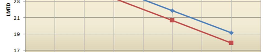
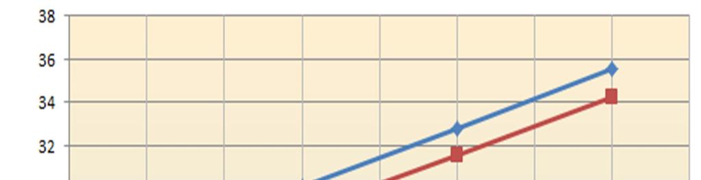

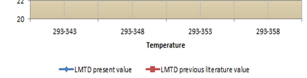
5 Fig.6: Validation of results Fig.7: Validation of results for varying the hot fluid temperature 3251

6 The velocity contours are for the inlet temperature change is given below; Fig.7: Velocity contour for temperature inlet ( )K IV. CONCLUSION The heat transfer and flow distribution is discussed in detail and proposed model is compared with existing literature [08]. The model predicts the heat transfer and pressure drop with an average error of 11.25%. The assumption worked well in this geometry and meshing expects the outlet and inlet region where rapid mixing and change in flow direction takes place. Thus improvement is expected if the helical tube used in the model should have complete contact with the surface of the flow domain, it will help in more turbulence across tube and the heat transfer rate will increase. If different flow rate is taken, it might be help to get better heat transfer and to get better temperature difference between inlet and outlet. Moreover the model has provided the reliable results by considering the standard k-epsilon and standard wall function model, but this model over predicts the turbulence in regions with large normal strain. Thus this model can also be improved by using higher computational theory. However the model shows a better heat transfer characteristics from the existing literature [08] with an average error for the LMTD is 8.5% for step changing the cold fluid temperature and 8.9% for varying the hot inlet temperature. REFRENCES [1] Muley, A., and R. M. Manglik. "Experimental study of turbulent flow heat transfer and pressure drop in a plate heat exchanger with chevron plates." Journal of heat transfer (1999): [2] Leu, Jin-Sheng, Ying-Hao Wu, and Jiin-Yuh Jang. "Heat transfer and fluid flow analysis in plate-fin and tube heat exchangers with a pair of block shape vortex generators." International Journal of Heat and Mass Transfer (2004): [3] Hwang, Seong Won, et al. "CFD analysis of fin tube heat exchanger with a pair of delta winglet vortex generators." Journal of Mechanical Science and Technology 26.9 (2012): [4] Jayakumar, J. S., et al. "Experimental and CFD estimation of heat transfer in helically coiled heat exchangers." Chemical engineering research and design 86.3 (2008): [5] Mandal, Monisha Mridha, and Krishna DP Nigam. "Experimental study on pressure drop and heat transfer of turbulent flow in tube in tube helical heat exchanger." Industrial & Engineering Chemistry Research (2009): [6] Mohammed, H. A., et al. "Heat transfer and fluid flow characteristics in microchannels heat exchanger using nanofluids: a review." Renewable and Sustainable Energy Reviews 15.3 (2011): [7] Das, Prasanta Kumar, and Indranil Ghosh. "Thermal design of multistream plate fin heat exchangers a state-of-the-art review." Heat Transfer Engineering (2012): [8] Nagarsheth, Shaival H., Dhruvi S. Bhatt, and Jayesh J. Barve. "Temperature profile modelling, simulation and validation for a counter flow water tube in tube heat exchanger." Control Conference (ICC), 2017 Indian. IEEE,