Unincorporated Summit County Storm Water Management Plan June 2015
|
|
|
- Wilfred Griffin
- 6 years ago
- Views:
Transcription
1 Summit County Storm Water Management Plan June 2015 Unincorporated Summit County Storm Water Management Plan June 2015 Summit County Engineering 60 North Main PO Box 128 Coalville, UT
2 Summit County Storm Water Management Plan June 2015 Table of Contents Section Title Page 0.0 General Information 0.1 Introduction Community Information Responsible Persons Threatened or Endangered Species Historic Properties Local Water Quality Concerns Impaired Waters Appendices Public Education and Outreach 1.1 Overview Summary of Existing Efforts Plan and Implementation Measures Public Involvement and Participation 2.1 Introduction Summary of Existing Efforts Plan and Implementation Measures Illicit Discharge Detection and Elimination 3.1 Introduction Summary of Existing Efforts Plan and Implementation Measures Construction Site Runoff Control 4.1 Introduction Summary of Existing Efforts Plan and Implementation Measures Long Term Storm Water Management in New Development and Re-Development 5.1 Introduction Summary of Existing Efforts Plan and Implementation Measures Pollution Prevention/Good Housekeeping 6.1 Introduction Summary of Existing Efforts Plan and Implementation Measures Glossary of Terms G-1 ii
3 Summit County Storm Water Management Plan June 2015 Appendices Appendix A Appendix B Appendix C Department of Water Quality Letter BMP List and Fact Sheets Ordinance 381 Storm Water Pollution Prevention Plan ii
4 Summit County Storm Water Management Plan June General Information 0.1 Introduction The Federal Clean Water Act requires that storm water discharges from certain types of facilities be authorized under storm water discharge Permits. (See 40 CFR ) The goal of the storm water Permits program is to reduce the amount of pollutants entering streams, lakes and rivers as a result of runoff from residential, commercial and industrial areas. The original 1990 regulation (Phase I) covered municipal (i.e., publicly-owned) storm sewer systems for municipalities over 100,000 population. The regulation was expanded in 1999 to include smaller municipalities as well. This expansion of the program to include small MS4s is referred to as Phase II. This Permit serves as a re-issuance or replacement of the previous General Permit for Discharges from Small Municipal Separate Storm Sewers (MS4s), UTR090000, issued December 9, This Permit is intended to cover new or existing discharges composed entirely of storm water from MS4s required by the State to obtain a Permit. Unincorporated Summit County was designated a MS4 in a letter dated December 18, 2014 to Summit County from the Department of Environmental Quality (Appendix A). The first step in this process is to submit a Notice of Intent (NOI) to receive confirmation that the MS4 is covered under the general permit. The next step is to prepare a Storm Water Management Plan (SWMP) which should do the following: 1. Reduce the discharge of pollutants from the MS4; 2. Protect water quality; and 3. Satisfy the appropriate water quality requirements of the Utah Water Quality Act. A SWMP is comprised of six minimum control measures that must be developed and implemented. These measures include: 1. Public Education and Outreach; 2. Public Involvement/Participation; 3. Illicit Discharge Detection and Elimination; 4. Construction Site Storm Water Runoff Control; 5. Long-Term Storm Water Management in New Development and Redevelopment (Post Construction Storm Water Management); and 6. Pollution Prevention and Good Housekeeping for Municipal Operations. They are discussed in the order given with the Measurable Goals, Implementation Schedule, and Fiscal Ability for each Best Management Practice (BMP). Fiscal Ability is the ability of the County to properly administer the BMP. The measurable goals are mandated by the EPA. A community must be showing improvement over time with these goals. The Implementation Schedule is also included in the section, indicating when the goals will be reached. To be in compliance with the Utah MS4 program, the County must document all inspections, enforcement actions, and public education activities. Annual reports of financial and employee resources must be submitted to the State of Utah Department of Environmental Quality by or on October 1 of every year. 0.2 Community Information Summit County is located in the northern part of Utah and occupies a rugged and mountainous area and was named as such due to the presence of 39 of the highest mountain peaks in Utah. As of the 2010 census, the population was 36,234 which are spread across 1,882 square miles. Of this area, 0-2

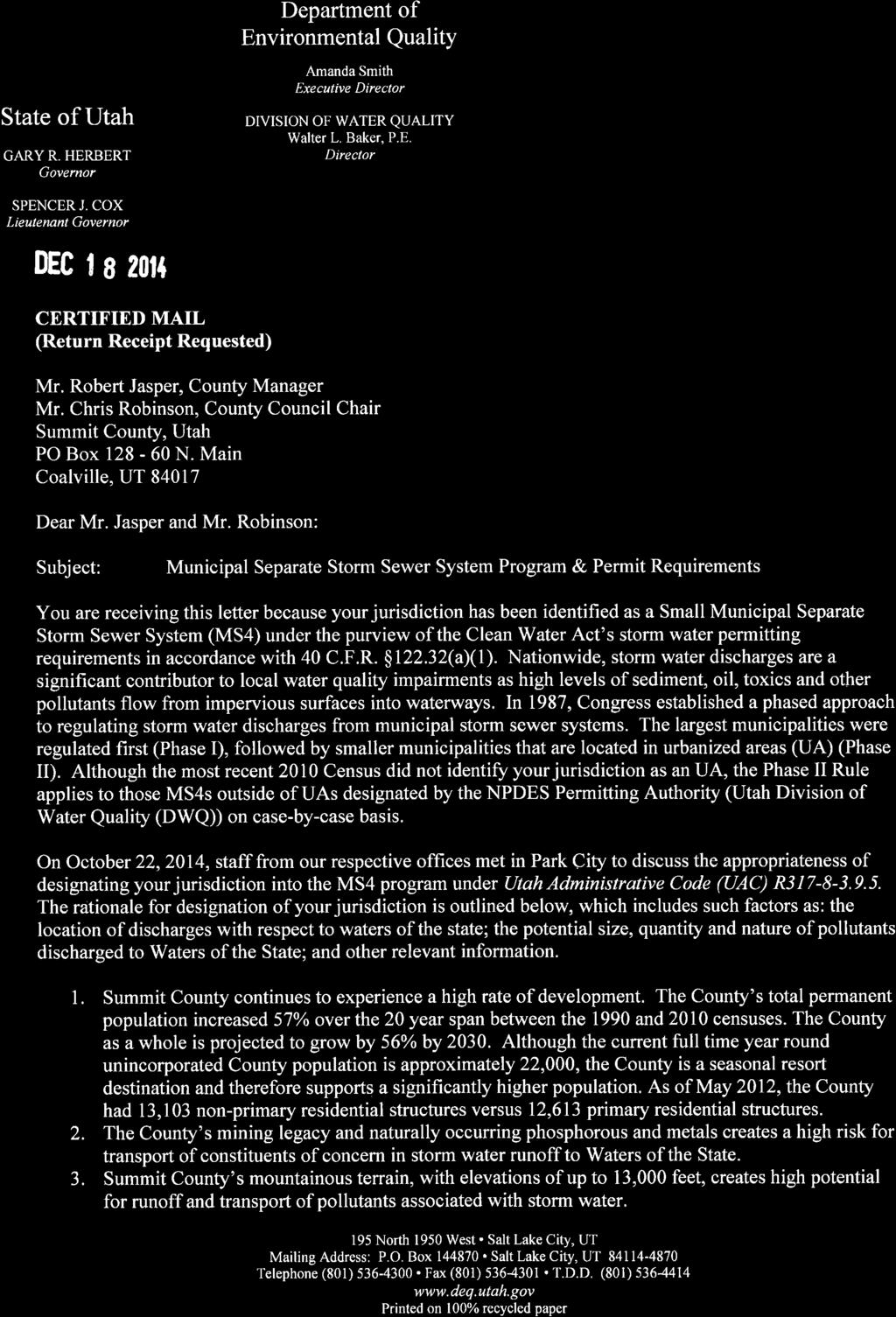
5 Summit County Storm Water Management Plan June 2015 approximately 10 square miles is covered by water. Portions of the Ashley National Forest and the Wasatch National Forest are in Summit County and include the Uinta Mountains, home of the highest peak in Utah. Rockport State Park is located within Summit County and is located on the Weber River which feeds Echo Reservoir. Annual precipitation in Summit County is averaged to be approximately 16 inches per year and snowfall averages 73 inches per year with more snowfall in the higher elevations. History Summit County was established in 1854 and Coalville was chosen as the County seat. Summit County was the home of the Northern Shoshone Indians hunting grounds until the arrival of the Mormon pioneers in The first settlers in Summit County chose their first settlement as Parley s Park and then Wanship in When coal was discovered near Coalville, the Mormon established a settlement there. The mining of coal was soon overshadowed by the discovery of more valuable minerals in the Wasatch Mountains and Park City was established as a mining town. Mining continued until the 1950 s and Park City was on the verge of becoming a ghost town. Due to the rugged terrain and deep snow, the area soon rebounded with the introduction of skiing and the Park City area is now a renowned winter sports destination. There are two distinct areas of Summit County. The Snyderville Basin consists of the land that is bordered by Salt Lake County on the west and Morgan County on the north. The boundary then heads south to the Silver Creek Junction area which is the intersection of Interstate 80 and US-40 and continues south to the Wasatch County boundary. The boundary then heads west along the Wasatch County border to the Salt Lake County border. The Snyderville Basin is illustrated in Figure 1. Figure 1: Snyderville Basin Area of Summit County ii
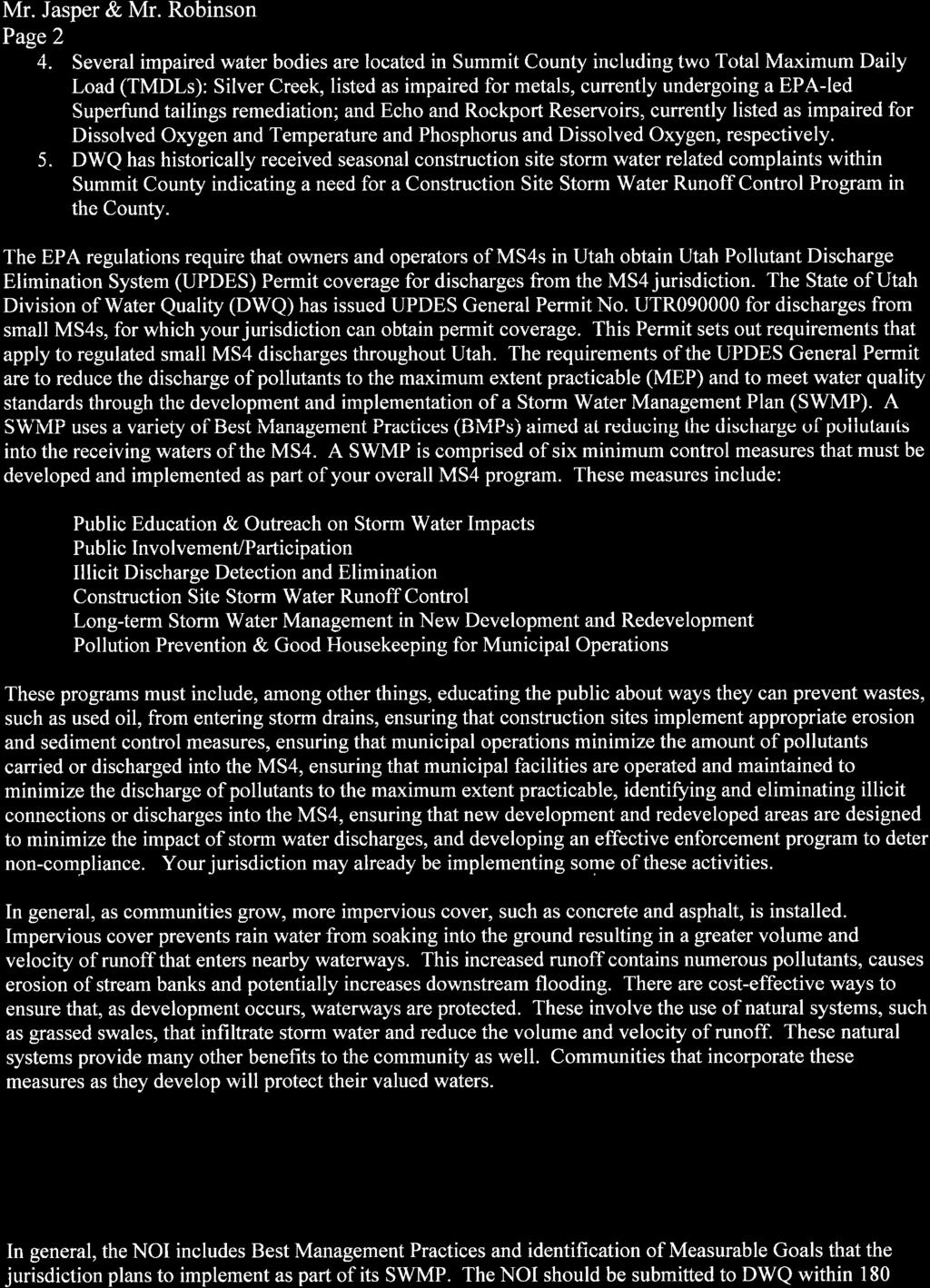
6 Summit County Storm Water Management Plan June 2015 Eastern Summit County remains very rural with five other municipalities: Francis; Kamas; Oakley; Coalville; and Henefer. Agriculture is the main economic driver in eastern Summit County however recreational opportunities are available with activities such as fly-fishing, cycling, snow-machining, dogsledding, and other outdoor activities. The high Uintas are part of the Eastern Summit County area and the entire Eastern Summit County is beginning to grow due to the population of the Snyderville Basin wishing for a more rural lifestyle. Eastern Summit County is illustrated in Figure 2. Storm Drain System The storm drain system consists of swales and ditches in the majority of Summit County. The exceptions are areas of the Snyderville Basin that include neighborhoods such as the Kimball Junction area, Silver Springs and the Canyons Ski Resort. Storm water from the Snyderville Basin eventually flows into East Canyon Creek which joins the Weber River in Wanship and flows into Echo Reservoir. Storm water from the Kamas Valley and the south side of the Uinta Mountains flows into either the Weber or Provo Rivers. Storm water also flows from the western portion of the Uinta Mountains into Chalk Creek which joins the Weber River near Coalville. Sanitary Sewer System Sanitary sewer service is provided to the Snyderville Basin area by the Snyderville Basin Water Reclamation District (SBWRD). They operate a water treatment plant near the Jeremy Ranch area of the basin and treat all the sanitary waste from Park City and unincorporated Summit County within the geographic region of the Snyderville Basin. In Eastern Summit County, each of the five municipalities offers a sanitary sewer treatment system. In Henefer, Francis, and Kamas, sanitary waste is treated by the use of sewer lagoons. In Oakley, a membrane bioreactor plant was constructed in 2003 to treat sanitary waste from the City limits, and in Coalville, a mechanical plant is used to treat all sanitary waste generated from areas within the city limits. In unincorporated Summit County, wastewater from resident and commercial areas are treated by septic systems with drain fields. 0.3 Responsible Persons The responsible persons for the Storm Water System are the current Public Works Director, and the County Engineer: Derrick Radke, Public Works Director 1775 South Hoytsville Road Coalville, UT Office: Leslie Crawford, Summit County Engineer 60 North Main PO Box 128 Coalville, UT Office: Threatened or Endangered Species The construction of storm water facilities in Summit County may result in effects to threatened or endangered (T&E) species. Threatened and endangered species are overseen by the Utah Division of Wildlife Resources. Current lists of T&E Species can be found at the following link: 0-3

7 Figure 2: Eastern Summit County
8 Summit County Storm Water Management Plan June Listed species for Summit County are: Common Name Scientific Name Status Brown (Grizzly) Bear Ursus arctos T Canada Lynx Lynx Canadensis T Extirpated Greater Sage-grouse Centrocercus urophasianus C Definitions: T = A taxon that is listed by the United States Fish and Wildlife Service as threatened with becoming endangered. T Extirpated = An endangered, threatened, or candidate taxon that is extirpated and considered by the United States Fish and Wildlife Service to no longer occur in Utah. C = A taxon for which the United States Fish and Wildlife Service has on file sufficient information on biological vulnerability and threats to justify it being a candidate for listing as endangered or threatened. A review of any site considered for storm water improvements should be made for these species during planning, design, and review. If possible impact may occur to these species, contact the Division of Wildlife Resources. 0.5 Historic Properties The construction of storm water facilities may result in effects to historic properties. Historic properties may include houses, buildings, ditches, headwalls, or other constructed features that are 50 or more years old. Where historic features are potentially affected, a qualified historian must undertake the following: Determine the extent and characteristics of the historic property; Determine the effect on the historic property; and Coordinate findings with the State Historic Preservation Office. There are many historic properties in Summit County as listed by the Utah Department of Heritage and Arts. They are listed at the link below: If further information is needed, contact the State Historic Preservation Office at the following link: Local Water Quality Concerns The water quality within Summit County is relatively good. Some of the stream or waterways in the County have been identified as protected under Section 303(d) of the Clean Water Act and the list is provided in the next section. The hope and intent of this SWMP is to possibly improve the water quality. 0-4
9 Summit County Storm Water Management Plan June 2015 The storm water in Summit County is transported in swales, ditches, canals, and rivers that allow for large amounts of infiltration. For the most part, the existing system has worked well. Continued growth is expected to put some pressure on canal, ditch and swale capacities. Summit County is currently controlling increased storm water runoff from development with localized detention and retention facilities as a design standard for commercial developments. Based upon the Total Maximum Daily Loads (TMDLs) of the river and creek listed below, target pollutants for Summit County have been identified as the following: Biochemical Oxygen Demand (BOD) Nitrate as N Total Nitrogen (TN) Total Phosphorous (TP) Total Dissolved Solids (TDS) Total Suspended Solids (TSS) E. coli Oil and Grease Turbidity Summit County s SWMP has been geared toward small rural applications, targeting the pollutants mentioned. The focus of this plan is meeting the requirements of the Phase II Small Municipal Separate Storm Sewer Systems Permit within the County, trying to stay in harmony with the rural nature and act within the existing budget structure. 0.7 Impaired Waters The water quality within Summit County is relatively good. Some of the streams or waterways in the County have been identified as protected under Section 303(d) of the Clean Water Act. They are listed in the table below. Waterway Kimball Creek Weber River East Canyon Creek Impaired Designated Use Group Cold Water Aquatic Life Cold Water Aquatic Life Cold Water Aquatic Life 0.8 Appendices This Storm Water Management Plan includes several appendices, which are as follows: 1. Appendix A MS4 Designation Letter 2. Appendix B BMP Fact Sheets 3. Appendix C Ordinance
10 Summit County Storm Water Management Plan June Public Education and Outreach Minimum Control Measure #1 1.1 Overview The operator of a regulated small MS4 must implement a multimedia public education program to distribute educational materials to certain focus groups as listed below: Residents; Business, institutions, and commercial facilities; Developers and Contractors; and Industrial Facilities. 1.2 Summary of Existing Measures Currently, Summit County contracts with Republic Services to provide garbage collection, waste services, and a recycling program. Educational materials are mailed to residents of Summit County informing them of the trash collection and recycling schedule as well as information on the types of recyclables that are accepted. Summit County, in cooperation with Recycle Utah and other entities, participates annually in a Water Festival to educate elementary school students on items related to water quality. Summit County provides a model that illustrates the effectiveness of erosion control measures as they related to construction and stabilization of the ground. This continues to be a successful event in which participation and attendance is growing. 1.3 Plan and Implementation Measures The Utah MS4 permit lists items that must be included in the SWMP. These are listed below with information regarding the targeted pollutant, type of BMP that will be used to satisfy the requirement, the targeted audience, how effectiveness will be measured, and a targeted completion date. The BMPs that are considered to meet the goal of public education and outreach are listed below along with the associated code that is used in Table 1. BMP Educational Materials Classroom Education on Storm Water Use of Media Employee Training Public Education and Participation Code EM CESW UM ET PEP 1-1
11 Pollutant(s) Trash, yard waste, chemicals Illicit discharge and waste Illicit discharge and waste Target Audience(s) Residents and Businesses General Public Businesses and Institutions Summit County Storm Water Management Plan Public Education and Outreach Desired Result Educate audiences about impacts from storm water discharge, ways to avoid, minimize and reduce impacts of storm water discharge, and actions individuals can take to improve water quality Information is provided to target audiences on prohibitions against illicit discharges and improper disposal of waste including: Maintenance of septic systems Effects of outdoor activities Lawn care Benefits of on site infiltration of storm water Effects of automotive work and car washing on water quality Disposal of swimming pool water Proper management of pet wastes Information is provided to target audience on prohibitions against illicit discharges and improper disposal of waste including: Lawn maintenance Benefits of appropriate on site infiltration of storm water Building and equipment maintenance Use of salt and other de icing materials Storage of materials Management of waste materials and dumpsters Management of parking lot surfaces Measurable Goal Support television and radio advertisements, and continue with water festival participation. Post information on website Include information on the County website Include information on the County website and produce and distribute a brochure that is targeted to business and commercial activities when a business license is obtained and renewed Milestone Date Ongoing Ongoing June 2016 and ongoing BMP EM, UM, PEP, and CESW EM, PEP, and UM EM, PEP, and UM Measure of Success Water Festival occurs annually, Information will be posted on website and made available at County locations such as the Health Information will be current on County website Information will be current on County website and included on all brochures that are distributed. Goal Completed Minimum Control Measure 1
12 Summit County Storm Water Management Plan Public Education and Outreach Pollutant(s) Illicit discharge and waste Target Audience(s) Contractors, Developers and plan review staff Desired Result Reduce adverse impacts from development sites Measurable Goal Assemble packets of information on SWPPP and BMPs that the contractor must read and sign when obtaining a building permit Milestone Date June 2016 BMP EM Measure of Success Water Festi al Information packets are signed for every new development Goal Completed Illicit discharge and waste All pollutants All pollutants All pollutants Employees Permitee engineers, development and plan review staff, land use planners All Audiences All audiences Information is provided to target audience on prohibitions against illicit discharges and improper disposal of waste including: Equipment inspection to ensure timely maintenance Benefits of appropriate on site infiltration of storm water Minimize use of salt or other de icing materials Storage of industrial materials Management of waste materials and dumpsters Management of parking lot surfaces Training on Low Impact Development (LID), green infrastructure and post construction BMPs Evaluate the effectiveness of the public education program by a defined method Document why certain BMPs were chosen for public education program (over others) Have training annually on illicit discharges Require an annual meeting with all development and plan review staff and land use planners to review the County s LID goals. Research evaluation methods and select the best one. Implement. Include an explanation in the SWMP Ongoing June 2016 October 2016 June 2015 ET ET PEP Training occurs annually Training occurs annually Evaluation method chosen (2016) and implemented (2016) Documented rationale included in the Jun 15 Minimum Control Measure 1
13 Summit County Storm Water Management Plan June Public Involvement and Participation Minimum Control Measure #2 2.1 Introduction Involving the public is key to any successful SWMP. Representatives from stakeholder groups need to have the ability to be involved and participate in the program through various means. Groups that may be involved include: Residences; Commercial and Industrial Businesses; Trade Associations; Environmental Groups; Homeowner Associations; and Education Organizations. To involve these groups, Summit County currently follows the public notification process for public meetings. This allows members from each of the stakeholder groups to provide input into the SWMP. In addition to this notice, the County has placed the SWMP on the website for public review and comments. Each year after June 30, the County will review any comments on the program operation for the year and implement changes as needed. The County Council will review and approve any changes to the program. 2.2 Summary of Existing Efforts Jurisdictions within Summit County contract with Republic Services for waste management services which include a recycling program. The program reduces solid waste by recycling and offers proper disposal options for hazardous wastes that can be difficult to dispose of, thereby preventing storm water contamination due to improper disposal of hazardous wastes and solids. The landfill accepts: cardboard, newspaper, aluminum cans, tin/steel cans, plastic pop bottles, plastic milk jugs, green waste, aluminum scrap, ferrous metals, tires, used oil, oil filters, antifreeze, carpet pad, batteries, wood pallets, and mixed paper on site for recycling. 2.3 Plan and Implementation Measures In order to help meet the goals and objectives of the SWMP, Summit County has chosen to adopt the following BMPs for use within our County as applicable. Each BMP is cross referenced alphabetically by code to a fact sheet that describes the BMP, its applicability, its limitations, and its effectiveness in the BMP Appendix. BMP Community Hotline Public Education/Participation Service Group Participation Storm Drain System Signs Code CH PEP SGP SDSS In order to more fully realize the benefit of the BMP, the County has set the following goals. The goals set along with the existing efforts fulfill the requirements of the Final Storm Water Phase II Rule for Public Participation and Involvement. 2-1
14 Pollutant(s) Target Audience(s) Summit County Storm Wate Management Plan Public Involvement/Participation Desired Result Measurable Goal Milestone Date BMP Measure of Success Goal Completed All Pollutants General Public Have a program or policy in place that allows for the public to provide input Notify the public 30 days in advance of the County Council meeting when the SWMP will be reviewed May 2015 PEP Public was notified Apr 15 All pollutants General Public Have SWMP document available for public review before it is submitted to the State Have a hard copy of the draft permit available at the County offices May 2015 PEP SWMP is available for public a week before public hearing All pollutants General Public Have SWMP document available to the public at all times Post the SWMP on the County website June 2015 PEP SWMP is updated and posted on the website Apr 15 All pollutants General Public Make updated SWMP document available to the public annually Post updated SWMP annually Ongoing PEP SWMP is updated and posted on the website annually All pollutants All Create a list of potential service projects that can improve storm water quality Develop a list of projects for scout and community service groups Annually, Ongoing SPL Record the number of projects completed annually All Pollutants All Place storm water information signs at locations throughout the County Review options for placement of signs at facilities with needed agencies. Explore costs for sign placement. Install signs. June 2016 SDSS Number of signs placed throughout the County. Reduced number of illegal dumping and discharge Minimum Control Measure 2
15 Pollutant(s) Target Audience(s) Summit County Storm Wate Management Plan Public Involvement/Participation Desired Result Measurable Goal Milestone Date BMP Measure of Success Goal Completed All Pollutants All Establish a community hotline for reporting storm water related incidents Explore alternatives for establishing the hotline via phone or . Implement hotline selected alternative June 2016 CH Established Hotline Minimum Control Measure 2
16 Summit County Storm Water Management Plan June Illicit Discharge Detection and Elimination Minimum Control Measure #3 3.1 Introduction Illicit discharges are non-storm water discharges that enter into natural water bodies through various methods and means. The Illicit Discharge Detection and Elimination (IDDE) control measure is intended to prevent illicit connections and discharges to natural drainages by monitoring outfalls, performing inspections of County owned facilities and maintaining inventories of storm water infrastructure. 3.2 Summary of Existing Efforts An existing County ordinance exists that allows the County to charge the negligent party for the cost of cleanup when a hazardous spill occurs. Currently, reports of spills are handled through 911 Dispatch. When reported to dispatch, spill reports are logged and assessed and addressed by the Summit County Health Department, the Fire District that has jurisdiction in the area of the spill, and other local hazardous material response teams. The county has not generally experienced problems with individuals or businesses illicitly connecting their sanitary waste water piping to storm drains. More common types of illicit discharges include septic tank overflows, spills from highway accidents, and concrete truck wash out water. Although it has not been documented, it is also suspected that some homeowners dump used oil, antifreeze and household chemicals into ditches. 3.3 Plan and Implementation Measures In order to help meet the goals and objectives of the SWMP, Summit County has chosen to adopt the following BMPs for use within our County as applicable. Each BMP is cross referenced alphabetically by code to a fact sheet that describes the BMP, its applicability, its limitations, and its effectiveness in the BMP section, BMP Community Hotline Public Education/Participation Ordinance Development Illegal Dumping Controls Map Storm Water Drains Non-Storm Water Discharge to Drains Illegal Solids Dumping Controls Employee Training Used Oil Recycling Hazardous Waste Management Hazardous Materials Storage Mapping Septic System Controls Code CH PEP OD IDC MSWD NSWD ISDC ET UOR HWM HMSM SSC In order to more fully realize the benefits of the BMPs listed above, the County has set the following goals. The goals set along with the existing efforts fulfill the requirements of the Final Storm Water Phase II Rule for Illicit Discharge Detection and Elimination. 3-1
17 Summit County Storm Water Management Plan June 2015 Initial enforcement of this rule will be by the Summit County Engineering and Health Departments with support from the Summit County Attorney and Sheriff s Office. 3-2
18 Summit County Storm Water Management Plan Illicit Discharge Detection and Elimination Pollutant(s) Target Audience(s) Desired Result Measurable Goal Milestone Date BMP Measure of Success Goal Completed All Pollutants Contractors, Developers, County Council Enforcement ability for storm water rules Adapt existing ordinance to conform with new permit June 2016 OD Ordinance is in place and meets the permit requirements Implement a system to map new culverts from development June 2016 MSWD System in place for mapping new culverts N/A Development Services Maintain Storm Water System Map Map all new culverts installed with development Map remaining road crossing culverts October 2016 MSWD October 2016 MSWD A current map of all new culverts in the County jurisdiction All known crossing culverts are shown on the map Continue implement policy. Have all map updates done annually Ongoing MSWD 90% of all culverts are placed on the map annually All Pollutants All Audiences Develop, implement, and prepare in writing a plan to detect and address non storm water discharges Develop systematic written procedures on process June 2016 NSWD Have procedure in place All Pollutants All Audiences Develop, implement, and prepare in writing a plan to detect and address non storm water discharges Conduct dry weather screening of 20% of outfalls each year Ongoing NSWD All planned screenings are done each year Hazardous Materials All Audiences Map locations of hazardous materials in the County Update Hazardous Waste Map each year October 2016 HMSM A maintained current map Minimum Control Measure 3
19 Summit County Storm Water Management Plan Illicit Discharge Detection and Elimination Pollutant(s) Target Audience(s) Desired Result Measurable Goal Milestone Date BMP Measure of Success Goal Completed All Pollutants All Audiences Develop and implement standard operating procedures (SOP) for characterizing the nature of any illicit discharges found or report to the Permitee by the County Hotline Create an Incident Response Flow Chart and train personnel Review flow chart and SOP with staff and provide training annually October 2016 IIC, CH October 2016 IIC, CH Staff is following flow chart Training completed annually for all staff involved in incident reporting All Pollutants All Audiences Develop and implement SOP for ceasing the illicit discharge Create the Incident Flow Chart and train personnel October 2016 ISC, ISDC Incident Flow Chart is created All Pollutants Public Employees, Businesses, and Residents Inform public employees, businesses, and general public of hazards associated with illicit discharges and improper disposal of waste See Section 2.0 October 2016 PEP, ET See Section 2.0 Household Hazardous Wastes Residents Promote or provide services for the collection of household hazardous wastes Put the Household Hazardous Waste address and phone number on County website June 2016 UOR, HWM Complete Household Hazardous Wastes Residents Publicly list and publicize a hotline or other telephone number for public reporting of spills and other illicit discharges Put the Household Hazardous Waste address and phone number on County website June 2016 CH Complete All Pollutants All Audiences Adopt and implement procedures for program evaluation and assessment. Include a database for mapping, tracking of spills or illicit discharges identified and inspections conducted Create a spreadsheet for tracking of illicit discharges June 2016 IIC, MSWD Complete Minimum Control Measure 3
20 Summit County Storm Water Management Plan Illicit Discharge Detection and Elimination Target Pollutant(s) Audience(s) All Pollutants All Audiences Desired Result Prepare plan for non storm water discharges Measurable Goal Identify high priority outfalls and provide inspection schedule Milestone Date June 2016 BMP SSC, NSWD Measure of Success Complete Goal Completed Minimum Control Measure 3
21 Summit County Storm Water Management Plan June Construction Site Runoff Control Minimum Control Measure #4 4.1 Introduction Runoff from construction sites can be a large contributing factor to storm water pollution. By controlling construction site runoff through planning, design, and construction BMPs, pollution to natural water bodies can be greatly reduced. Review of erosion control plans, Storm Water Pollution Prevention Plans and regular site inspections aid in implementation of this control measure to reduce non-storm water discharges. 4.2 Summary of Existing Efforts Construction inspectors routinely visit construction sites in Summit County and have the ability to assess citations and notices of violation if there are storm water violations. 4.2 Plan and Implementation Measures In order to help meet the goals and objectives of the SWMP, Summit County has chosen to adopt the following BMPs for use within our County as applicable. Each BMP is cross referenced alphabetically by code to a fact sheet that describes the BMP, its applicability, its limitations, and its effectiveness in the BMP section. BMP Erosion Control Plan Establish/Compile Design Standards Dust Controls Silt Fence Straw Bale Barrier Temporary Drains and Swales Contractor Certification and Inspector Training Stabilized Construction Entrance Public Education and Participation Portable Toilets Infrastructure Planning Concrete Waste Management Ordinance Development Zoning Code ECP ECDS DC SF STB TDS CCIT SCE PEP PT IP CWM OD ZO In order to more fully realize the benefit of the BMP, Summit County has set the following goals. The goals set along with the existing efforts fulfill the requirements of the Final Storm Water Phase II Rule for Construction Site Runoff Control. 4-1
22 Summit County Storm Water Management Plan Construction Site Storm Water Runoff Control Pollutant(s) Target Audience(s) Desired Result Measurable Goal Milestone Date BMP Measure of Success Goal Completed Sediment, Construction Site Debris, Hydrocarbons Contractors and Developers Raise awareness of contractors and developers on what is expected on construction sites Establish minimum required lot size for permit. Require a SWPPP for every construction site over required size Ongoing OD, PEP 95% of all required construction sites have a working SWPPP Sediment, Construction Site Debris, Hydrocarbons Contractors and Developers Develop a written enforcement strategy and implement the enforcement provisions of the ordinance or other regulatory mechanism Amend existing ordinance to include escalating enforcement provisions June 2016 OD Complete Sediment, Construction Site Debris, Hydrocarbons Contractors and Developers, County Council, Plan Reviewers Require construction operators to have a SWPPP and BMPs in place per permit Draft ordinance to require a SWPPP on every active construction site as determined May 2015 OD Ordinance in place and meets the permit requirement May 2015 Sediment, Construction Site Debris, Hydrocarbons Contractors and Developers, County Council, Plan Reviewers Documentation and tracking of all enforcement actions Develop and begin using a construction site enforcement action log/database June 2016 OD Create, use, and update log Sediment, Construction Site Debris, Hydrocarbons Sediment, Construction Site Debris, Hydrocarbons Contractors and Developers Contractors and Developers Develop and implement SOPs for preconstruction SWPPP review for construction sites Conduct a pre construction meeting Develop checklist and begin to do preconstruction reviews of SWPPP Hold pre construction meetings on all common plans of development and high priority construction sites May 2015 June 2016 ECP PEP Conduct SWPPP reviews Conduct and document preconstruction meetings May 2015 Minimum Control Measure 4
23 Summit County Storm Water Management Plan Construction Site Storm Water Runoff Control Pollutant(s) Target Audience(s) Desired Result Measurable Goal Milestone Date BMP Measure of Success Goal Completed Sediment, Construction Site Debris, Hydrocarbons Incorporate into the SWPPP review procedures the consideration of potential water quality impacts and procedures for pre construction review which shall include the use of a checklist Develop a policy to consider potential water quality impacts on all projectsprivate or County September 2016 ZO Postconstruction BMPs in place on 50% of all projects Sediment, Construction Site Debris, Hydrocarbons Contractors and Developers Incorporate into the SWPPP review procedures for an evaluation of opportunities for the use of Low Impact Development (LID) and green infrastructure and when the opportunity exists, encourage such BMPs to be incorporated into the site design Develop a policy to consider Low Impact Development (LID) practices on all projects private or County September 2016 ZO LID practices on 25% of all projects Sediment, Construction Site Debris, Hydrocarbons Contractors and Developers Identify priority construction sites, including at a minimum, those construction sites discharging directly into or immediately upstream of waters that the State recognizes as impaired or high quality Review construction projects using SWPPP preconstruction review to determine if a site is a priority June 2016 ECP Documented preconstruction review Sediment, Construction Site Debris, Hydrocarbons Contractors and Developers Inspections of required construction sites at least monthly by qualified personnel Conduct monthly inspections of required construction sites June 2016 CCIT 90% of required construction sites are inspected monthly Minimum Control Measure 4
24 Summit County Storm Water Management Plan Construction Site Storm Water Runoff Control Pollutant(s) Target Audience(s) Desired Result Measurable Goal Milestone Date BMP Measure of Success Goal Completed Sediment, Construction Site Debris, Hydrocarbons Contractors and Developers The County must include a procedure for being notified by construction operators/owners of their completion of active construction so that verification of final stabilization and removal of all temporary control measures may be conducted Develop a written Notice of Termination (NOT) process for used within the County Train SWPPP inspectors, their supervisors, and any personnel who grant final occupancy permits on the NOT process September 2016 September 2016 ECP ECP 95% of all construction sites are terminated appropriately 95% of all construction sites are terminated appropriately Sediment, Construction Site Debris, Hydrocarbons Contractors and Developers Conduct bi weekly inspections on high priority construction sites Inspect high priority sites biweekly June 2016 ECP All high priority construction sites are inspected biweekly Sediment, Construction Site Debris, Hydrocarbons Contractors and Developers Provide training to County staff and third party designers Develop a County policy to require all SWPPP inspectors to be a qualified inspector per the Construction General Permit within six months June 2016 CCIT Complete Minimum Control Measure 4
25 Summit County Storm Water Management Plan June Long Term Storm Water Management in New Development and Re- Development Minimum Control Measure #5 5.1 Introduction The intent of Long Term Storm Water Management is to maintain post-construction runoff conditions to those of pre-construction runoff. This pertains to both quantity and quality. Techniques such as Low Impact Development (LID) are encouraged to be used when designing for Long Term Storm Water Management. Long Term Storm Water Management applies to sites over one acre in size and sites less than one acre when part of a common plan of development. Applicability of this minimum control measure also pertains to private and public development sites including roads. When re-development of an area occurs within the community, considerations to reduce storm water runoff and improve water quality must be considered. 5.2 Summary of Existing Efforts Currently, the County has an existing Storm Water Pollution Prevention Ordinance that requires Storm Water Pollution Prevention Plan (SWPPP) applications and plans. Each is reviewed by Registered Storm Water Inspectors (RSI) and/or engineers and the Engineering Department conducts inspections. The County also collects bonds at the time of building permit and holds them until final stabilization of the site is complete. 5.3 Plan and Implementation Measures In order to help meet the goals and objectives of this SWMP, Summit County has chosen to adopt the following BMPs for use within our County as applicable. Each BMP is cross referenced alphabetically by code to a fact sheet that describes the BMP, its applicability, its limitations, and its effectiveness in the BMP section. BMP Educational Materials Ordinance Development Land Use Planning/Management Zoning Seeding and Planting Map Storm Water Drains Riprap Rock Check Dams Infrastructure Planning BMP Inspection and Maintenance Infiltration Code EM OD LUPM ZO SP MSWD RR CD IPL BMPIM IN 5-1
26 Summit County Storm Water Management Plan June 2015 In order to more fully realize the benefit of the BMP, the County has set the following goals. The goals set along with the existing efforts fulfill the requirements of the Final Storm Water Phase II Rule for Post Construction Runoff Control. 5-2
27 Target Pollutant(s) Audience(s) All Pollutants All Audiences All Pollutants All Audiences All Pollutants All Audiences Summit County Storm Water Management Plan Long Term Storm Water Management in New Development and Re development Desired Result Measurable Goal Milestone Date BMP Develop and adopt an ordinance or other regulatory mechanism that requires long term post construction storm water controls at new development and re development sites. Develop and adopt an ordinance or other regulatory mechanism that requires long term post construction storm water controls at new development and re development sites. Documentation of how the requirements of the ordinance or other regulatory mechanism will protect water quality and reduce the discharge of pollutants to the MS4 Amend ordinance that meets requirements of the new permit June 2016 OD Amend ordinance June 2016 OD Develop a checklist of targeted BMPs for selection and their benefits June 2016 IPL Adopt revised standard September 2016 IPL Measure of Success Reviews are complete Successful passage of ordinance Draft is complete by milestone date Goal Completed All Pollutants All Pollutants All Pollutants All Audiences MS4 Staff, County Council MS4 Staff, Contractors and Developers Develop a process to evaluate and encourage a LID approach The Permitee must develop a plan to retrofit existing develop sites that are adversely impacting water quality Each Permitee shall develop and define specific hydrologic method or methods for calculating runoff volumes and flow rates, etc. Review implementing LID approaches in the development review process Review water quality standards at re developing sites Review existing design standards to see if they meet new permit requirements Update design standards to meet permit requirements September 2016 September 2016 September 2016 September 2016 IPL IPL IPL IPL Inclusion of LID in the development review process Improvement storm water facilities to redeveloped sites Standards have been reviewed and comments documented Updated standards have been adopted Minimum Control Measure 5
28 Summit County Storm Water Management Plan Long Term Storm Water Management in New Development and Re development Pollutant(s) Target Audience(s) Desired Result Measurable Goal Milestone Date BMP Measure of Success Goal Completed All Pollutants MS4 Staff, Contractors and Developers Review Storm Water Pollution Prevention Plans (SWPPPs) See goals from Section 4.0 September 2016 All Pollutants MS4 Staff, Contractors and Developers Permitees shall provide developer and contractors with preferred design specifications to more effectively treat storm water for different development types for projects located in, adjacent to, or discharging to environmentally sensitive areas Locate and map environmentally sensitive areas within the MS4 Review map of sensitive areas and identify preferred method(s) of treating storm water to discharge to those areas September 2016 September 2016 IPL IPL Completed map identifying environmentally sensitive areas List of preferred method(s) All Pollutants MS4 Staff, Contractors and Developers Permitees shall keep a representative copy of information that is provided to design professionals, the dates of the mailings, and the list of recipients Keep a revision log for information in Appendix A Supplemental Guide to Contractors and Developers Log name and date of distribution of Supplemental Guide to Contractors and Developers June 2016 EM Revision log is complete June 2016 EM Log is current All Pollutants MS4 Staff, Contractors and Developers All Permitees shall adopt and implement SOPs or similar types of documents for site inspection and enforcement of post construction storm water control measures Review and customize SOPs for inspection and enforcement of postconstruction control measures June 2016 LIP Inspection and enforcement SOPs are current and utilized Minimum Control Measure 5
29 Pollutant(s) All Pollutants All Pollutants Target Audience(s) MS4 Staff, Contractors and Developers MS4 Staff, Contractors and Developers Summit County Storm Water Management Plan Long Term Storm Water Management in New Development and Re development Desired Result Measurable Goal Milestone Date BMP Require private property owner/operators or qualified third parties to conduct maintenance and provide annual certification that adequate maintenance has been performed and the structural controls are operating as designed to protect water quality. In this case, the Permitee must require a maintenance agreement addressing maintenance requirements for any control measures installed on site. Inspections and any necessary maintenance must be conducted annually by either the Permitee or through a maintenance agreement with the property owner/operator. On sites were the property owner/operator is conducting maintenance, the Permitee shall inspect those storm water control measures at least once every five years. Draft a maintenance agreement template Adopt a maintenance agreement template Inventory post construction BMPs Identify responsible person to inspect and/or maintain each post construction BMP Develop inspection report form for post construction BMPs Conduct inspections annually for county owned BMPs Conduct inspections on privately owned BMPs on at least 20% of BMPs per year September 2016 BMPI, M September 2016 BMPI, M June 2017 June 2017 June 2017 June 2017 June 2017 BMPI. M BMPI, M BMPI, M BMPI, M BMPI, M Measure of Success Draft is complete by milestone date Template is adopted and used by milestone date Inventory is complete List identifies person responsible for inspections and maintenance Form is completed Completed inspection reports are properly filed Complete inspection reports are properly filed Goal Completed All Pollutants MS4 Staff Permitees shall provide adequate training for all staff involved in postconstruction storm water management, planning and review, and inspections and enforcements. Schedule and conduct training for appropriate personnel September 2016 BMPI, M If all appropriate personnel are trained Minimum Control Measure 5
30 Target Pollutant(s) Audience(s) All Pollutants MS4 Staff Summit County Storm Water Management Plan Long Term Storm Water Management in New Development and Re development Desired Result Measurable Goal Milestone Date BMP Maintain an inventory of postconstruction BMPs Inventory log updated annually June 2017 Measure of Success Lot is updated annually Goal Completed Minimum Control Measure 5
31 Summit County Storm Water Management Plan June Pollution Prevention/Good Housekeeping Minimum Control Measure #6 6.1 Introduction The intent of the Pollution Prevention/Good Housekeeping control measure is to maintain and construct County owned facilities in such a way to prevent pollutants from entering into the storm water system. This is accomplished by developing and implementing an operation and maintenance program, outlining standard operation procedures (SOPs) and defining roles and responsibilities of staff overseeing the SWMP. 6.2 Summary of Existing Efforts The County currently maintains catch basins, detention ponds, and pipes and culverts as needed. Summit County also participates in a recycling program and provides recycling containers for residents to use at the curb. Summit County operates with a limited amount of equipment. This equipment is primarily cleaned and maintained at the Public Works Department facility located in Wanship. Equipment is fueled at this location as well. The County also stores equipment and materials at the Wanship facility and other facilities throughout the County. Salt and sand are stored under cover to reduce transport of pollutants during rain events. Table 6-1 provides a list of activities potential sources of pollutants that result from the activities. Table 6-1 Activity Pollutant Potential Source Construction Sediment Poor erosion control practices on hillsides, undeveloped property, right of way for construction sites Residential and Nutrients Yard debris, garbage, fertilizer and pesticide use, Parks Transportation and Commercial Residential Parks and Residential Commercial and Residential Residential and Parks Metals Oxygen demanding Substances Bacteria and Viruses Oil, Grease, and Hydrocarbons Floatables rat poison, pyrotechnics Paint, plastics, pottery pigments and glazes, automobile tires, common galvanized coatings, pesticide use, root killer application on sewer lines, old lead paint an glazes, wood preservatives, batteries Yard debris, animal wastes, organic chemical use Human and animal (pets and aquatic life) waste, sanitary sewer infiltration into storm drain system, decomposing yard waste Asphalt surface leaching, spills, leaks, construction activities Street refuse, industrial yard waste 6-1
32 Summit County Storm Water Management Plan June Plan and Implementation Measures In order to help meet the goals and objectives of this SWMP, Summit County has chosen to adopt the following BMPs for use within our County as applicable. Each BMP is cross referenced alphabetically by code to a fact sheet that describes the BMP, its applicability, its limitations, and its effectiveness in the BMP section. BMP BMP Inspection and Maintenance Long Term Operation and Maintenance Street Cleaning (Parking Lots) Catch Basin Cleaning Employee Training Building and Grounds Maintenance Area Control Procedures De-Icing Chemical Use Storage Material Use Housekeeping Practices Infrastructure Planning Animal Carcass Planning Concrete Waste Management Establish/Compile Design Standards Illegal Dumping Control Inspection and Maintenance Portable Toilets Sorbents Used Oil Recycling Code BMPIM LTOM SC CBC ET BGM ACP DCUS MU HP IPL ACR CWM ECDS IDC IM PT SO UOR In order to more fully realize the benefit of the BMP, the County has set the following goals. The goals set along with the existing efforts fulfill the requirements of the Final Storm Water Phase II Rule for Pollution Prevention/Good Housekeeping. 6-2
33 Summit County Storm Water Management Plan Pollution Prevention and Good Housekeeping for Municipal Operations Target Pollutant(s) Audience(s) Desired Result Measurable Goal Milestone Date BMP Measure of Success Goal Completed All Pollutants MS4 Staff All components of an operations and maintenance (O&M) program shall be included in the SWMP document and must identify the department, and were appropriate, the specific staff responsible for performing each activity described in this sections. Complete organizational chart and define specific responsibilities for all departments shown September 2016 HP Organization chart is complete and up to date All Pollutants MS4 Staff Permitees shall develop and keep a written inventory current of permiteeowned or operated facilities Complete listing of MS4 owned/operated facilities September 2016 HP List is complete All Pollutants MS4 Staff All permitees must initially assess the written inventory of permitee owned and operated facilities, operations, and storm water controls identified above for the potential to discharge urban pollutants to storm water Complete assessments and identify high priority facilities September 2016 HP Assessments are complete and documentation recorded in SWMP All Pollutants MS4 Staff Each high priority facility identified above must develop a facility specific SOPs or similar type of documents Review, customize and update appropriate SOPs September 2016 HP SOPs are updated and current All Pollutants MS4 Staff Permitee must perform weekly visual inspecitons of high priority facilities in accordance with developed SOPs to minimize the potential for pollutant discharge Develop weekly inspection forms and log September 2016 HP Conduct weekly inspections June 2017 HP Completed inspection form and log At annual review, all weekly inspections are logged and reports completed Minimum Control Measure 6
34 Summit County Storm Water Management Plan Pollution Prevention and Good Housekeeping for Municipal Operations Target Pollutant(s) Audience(s) All Pollutants MS4 Staff All Pollutants MS4 Staff Desired Result At least once per quarter, a comprehensive inspection of highpriority facilities, including all storm water controls, must be performed At least once per quarter, the permitee must visually observe the quality of the storm water discharges from the high priority facilities Measurable Goal Develop quarterly inspection form and log Conduct quarterly comprehensive inspections Conduct quarterly visual observations of storm water discharges at high priority faciliites Milestone Date September 2016 June 2017 June 2017 HP HP HP BMP Measure of Success Complete inspection form and log At annual review, all quarterly inspections are logged and reports completed At annual review, all quarterly visual monitoring is complete, logged, and reports Goal Completed All Pollutants MS4 Staff, Contractors and Developers Permitee must develop and implement a process to assess the water quality impacts in the design of all new flood management structural controls that are associated with the permitee or that discharge to the MS4 Draft a policy/process to assess water quality impacts on all new flood control projects September 2016 HP Have policy approved June 2017 IPL A draft is prepared and ready for internal review Policy is approved and adopted All Pollutants MS4 Staff Existing flood management structural controls must be assessed to determine whether changes or additions should be made to improve water quality See Section 5.0 for goals September 2016 All Pollutants MS4 Staff Permitee shall provide training for all employees who have primary construction, operation, or maintenance job functions that are likely to impact storm water quality See individual training goals within other Sections Develop a training schedule June 2017 ET, HP Schedule is complete Minimum Control Measure 6
35 Summit County Storm Water Management Plan Pollution Prevention and Good Housekeeping for Municipal Operations Pollutant(s) Target Audience(s) Desired Result Measurable Goal Milestone Date BMP Measure of Success Goal Completed All Pollutants MS4 Staff Permitee shall provide training for all employees who have primary construction, operation, or maintenance job functions that are likely to impact storm water quality Conduct ongoing training according to schedule ET, HP Training is complete and documented according to schedule at annual evaluation Minimum Control Measure 6
36 Summit County Storm Water Management Plan June 2015 GLOSSARY OF TERMS Authorized Enforcement Agency: Employees or designees of the director of the municipal agency designated to enforce this ordinance. Berm: An earthen mound used to direct the flow of runoff around or through a structure. Best Management Practices (BMPs): Includes schedules of activities, prohibitions of practices, maintenance procedures, design standards, and other management practices to prevent or reduce the discharge of pollutants directly or indirectly into the waters of the United States. BMPs also include treatment requirements, operating procedures, educational activities, and practices to control plant site runoff spillage or leaks, sludge or waste disposal, or drainage from raw material storage. Bio-chemical Oxygen Demand in 5 (BOD5): A measure of the amount of oxygen that is consumed by bacteria as it breaks down organic matter in a sample during a five day period under standardized conditions. It is generally considered to be a measure of organic material in the water. Capital Improvement Plan (CIP): A plan developed by the County to identify and prioritize improvements that need to be made in upcoming years. Clean Water Act (CWA): The federal Water Pollution Control Act (33 U.S.C et seq.), and any subsequent amendments thereto. Code of Federal Regulations (CFR): Annual edition is the codification of the general and permanent rules published in the Federal Register by the departments and agencies of the Federal Government. It is divided into 50 titles that represent broad areas subject to Federal Regulations. Construction Activity: Activities subject to the National Pollutant Discharge Elimination System (NPDES) Construction Permits. These include construction projects resulting in land disturbance of 5,000 square feet or more. Such activities include but are not limited to clearing and grubbing, grading, excavating, and demolitions. Conveyance System: Any channel or pipe for collecting and directing the storm water. Culvert: A covered channel or large diameter pipe that directs water flow below the ground surface. Degradation: Biological or chemical degradation is the breakdown of chemical compounds into simpler substances, usually less harmful than the original compound, as with the degradation of a persistent pesticide. Geological degradation is the wearing down by erosion. Water degradation is the lowering of water quality of a watercourse by an increase in the amount of pollutants. Dike: An embankment to confine or control water, often built along the banks of a river to prevent overflow of lowlands; a levee. Directly Connected Impervious Areas (DCIA) Impervious surfaces that are directly connected to the storm drainage conveyance system. Directly connected means that there is no chance for infiltration or evapotranspiration before entering the conveyance system. Discharge: The release of storm water or other substance from a conveyance system or storage container. G-1
37 Summit County Storm Water Management Plan June 2015 Drainage: Refers to the collection, conveyance, containment, and/or discharge of surface and storm water runoff. Dry Weather Screening (DWS): The act of inspecting a storm drain system during dry weather to evaluate if there are any discharges to the system besides storm water. Erosion: The wearing away of land surface by wind or water. Erosion control occurs naturally from weather or runoff but can be intensified by land-clearing practices related to farming, residential, or industrial development, road building, or timber cutting. Fill: A deposit of earth material placed by artificial means. First Flush: The delivery of a disproportionately large load of pollutants during the early part of storms due to the rapid runoff of accumulated pollutants. General Permit: A permit issued under the NPDES program to cover a class or category of storm wawter discharges. Grading: The cutting and/or filling of the land surface to a desired slope or elevation. Hazardous Waste: By-products of society that can pose a substantial or potential hazard to human health or the environment when improperly managed. Possess at least one of four characteristics (flammable, corrosivity, reactivity, or toxicity), or appears on special Environmental Protection Agency (EPA) lists. Heavy Metals: Metals of high specific gravity, present in municipal and industrial wastes that pose longterm environmental hazards. Such metals include cadmium, chromium, cobalt, copper, lead, mercury, nickel, and zinc. Illicit Connection: Any physical connection to a publicly maintained storm water system allowing discharge of non-storm water which has not been permitted by the public entity responsible for the operation and maintenance of the system. Illicit Discharge: Any direct or indirect non-storm water discharge to the storm water system, except discharges from firefighting activities and other discharges exempted in this ordinance. Illicit Discharge Detection and Elimination (IDDE): A program that the County develops to identify and eliminate any illicit discharges they might have within their collection system. Impervious Surface: A surface which prevents or retards the penetration of water into the ground including, but not limited to, roofs, sidewalks, patios, driveways, parking lots, concrete, and asphalt paving, gravel, compacted native surfaces and earthen materials, and oiled macadam, or other surfaces which similarly impede the natural infiltration of storm water. Individual Permit: A permit issued under the NPDES program for a specific facility, whereby the unique characteristics of that facility may be addressed through the imposition of special conditions or requirements. Infiltration: The downward movement of water from the surface to the subsoil. The infiltration capacity is expressed in terms of inches/hour. Ingress/Egress: The points of access to and from a property. G-2
38 Summit County Storm Water Management Plan June 2015 Inlet: An entrance into a ditch, storm sewer, or other waterway. Low Impact Development (LID): This term is used to describe means and methods that can be utilized to reduce the impact of development on the environment. Minimum Control Measure (MCM): The EPA has identified six areas of focus for MS4s in developing a program to minimize the potential for pollutants to leave a jurisdiction and to enter the waters of the United States. The six areas of focus are called Minimum Control Measures (MCMs) and they include: 1. Public Education and Outreach; 2. Public Involvement; 3. Illicit Discharge Detection and Elimination; 4. Construction Site Storm Water Control; 5. Post Construction Storm Water Control; and 6. Pollution Prevention and Good Housekeeping. Municipal Separate Storm Sewer System (MS4): A municipally owned and operated storm water collection system that may consist of any or all of the following: curb and gutter, drainage swales, piping, ditches, canals, detention basins, inlet boxes, or any other system used to convey storm water that discharges into canals, ditches, streams, rivers, or lakes not owned and operated by that municipality. Mulch: A natural or artificial layer of plant residue or other materials covering the land surface which conserves moisture, holds soil in place, aids in establishing plant cover, and minimizes temperature fluctuations. National Pollutant Discharge Elimination System (NPDES): EPA s program to control the discharge of pollutants to waters of the United States. Non-point Source: Pollution caused by diffuse sources (not a single location such as a pipe) such as agricultural or urban runoff. NPDES Permit: An authorization, or license, or equivalent control document issued by EPA or an approved state agency to implement the requirements of the NPDES program. Off-site: Any area lying upstream of the site that drains onto the site and any area lying downstream of the site to which the site drains. On-site: The entire property that includes the property development. Outfall: The point, location, or structure where wastewater or drainage discharges from a sewer pipe, ditch, or other conveyance to a receiving body of water. Point Source: Any discernible, confined, and discrete conveyance including but not limited to any pipe, ditch, channel, tunnel, conduit, well, discrete fissure, container, rolling stock, concentrated animal feeding operation, or vessel or other floating craft, from which pollutants are or may be discharged. Plat: A map or representation of a subdivision showing the division of a tract or parcel of land into lots, blocks, streets, or other divisions and dedications. G-3
39 Summit County Storm Water Management Plan June 2015 Pollutant: Generally, any substance introduced into the environment that adversely affects the usefulness of a resource. Pollutants may include, but are not limited to: paints, varnishes and solvents; oil and other automotive fluids; non-hazardous liquid and solid wastes and yard wastes; refuse, rubbish, garbage, litter, or other discarded or abandoned objects and accumulations such that may cause or contribute to pollution floatables; pesticides, herbicides, and fertilizers; hazardous substances and wastes; sewage, fecal coliform and pathogens; dissolved and particulate metals; animal wastes; wastes and residues that result from construction a building or structure; and noxious or offensive matter of any kind. Receiving Waters: Bodies of water or surface water systems receiving water from upstream constructed (or natural) systems. Retention: The holding of runoff in a basin without release except by means of evaporation, infiltration, or emergency bypass. Riparian: A relatively narrow strip of land that borders a stream or river. Runon: Storm water surface flow or other surface flow which enters property other than that where it originated. Runoff: That part of precipitation, snow melt, or irrigation water that runs off the land into streams or other surface water that can carry pollutants from the air and land into the receiving waters. Sedimentation: The process of depositing soil particles, clays, sands, or other sediments that were picked up by runoff. Sheet Flow: Runoff which flows over the ground surface as a thin, even layer, not concentrated in a channel. Source Control: A practice or structural measure to prevent pollutants from entering storm water runoff or other environmental media. Stabilization: The proper placing, grading and/or covering of soil, rock, or earth to ensure its resistance to erosion, sliding, or other movement. Standard Operating Procedure (SOP): A written description of the standard method of performing a given task which can include a step-by-step description. SOPs are developed in an effort to bring consistency to a program and to clearly define the expectations of that program. They should be the asis of training programs for municipal employees. Storm Drain: A slotted opening leading to an underground pipe or open ditch for carrying surface runoff. Storm Water: Rainfall runoff, snow melt runoff, and drainage. It excludes infiltration. Storm Water Management Plan (SWMP): A document which describes the BMPs and activities to be implemented by a person or business to identify sources of pollution or contamination at a site and the actions to eliminate or reduce pollutant discharges to storm water, storm water conveyance systems, and/or receiving waters. G-4
40 Summit County Storm Water Management Plan June 2015 Storm Water Pollution Prevention Plan (SWPPP): A document which describes the general plan for addressing storm water pollutants at a given site. The plan characterizes the nature of the potential pollutants, describes methods and concepts for controlling those pollutants and identifies those responsible for the plan. Swale: An elongated depression in the land surface that is at least seasonally wet, is usually heavily vegetated, and is normally without flowing water. Swales direct storm water flows into drainage channels and allow some of the storm water to infiltrate into the ground surface. Total Maximum Daily Load (TMDL): In this permit, it refers to a study that accomplishes the following: 1. Quantifies the amount of a pollutant in a stream; 2. Identifies the sources of the pollutant; and 3. Recommends regulatory or other actions that may need to be taken in order for the impaired water body to meet water quality standards. Total Suspended Solids (TSS): An analytical measure of the amount of sediment suspended in water. TSS is typically comprised of larger sediment particles and does not include fine clays and silts that might be dissolved. Treatment Control BMP: A BMP that is intended to remove pollutants from storm water. Underground Injection Wells (UIW): A hole receiving storm water whose top dimension is narrower than the depth. Utah Pollutant Discharge Elimination System (UPDES): The State of Utah s program to control the discharge of pollutants to the water of the United States. Waters of the State: Surface waters and ground waters within the boundaries of the State of Utah and subject to its jurisdiction. Waters of the United States: Surface watercourses and water bodies as defined in 40 CFR 122.2, including all natural waterways and definite channels and depressions in the earth that may carry water, even though such waterways may only carry water during rains and storms and may not carry storm water at and during all times and seasons. Wetlands: An area that is regularly saturated by surface or ground water and subsequently characterized by a prevalence of vegetation that is adapted for life in saturated soil conditions. Examples include swamps, bogs, marshes, and estuaries. G-5
41 Summit County Storm Water Management Plan June 2015 Appendix A
42
43
44
45
46 Summit County Storm Water Management Plan June 2015 Appendix B
47 Minimum Control Measure Combined BMPs Abbreviation Public Education and Outreach Public Participation and Involvement Illicit Discharge Detection and Elimination Construction Site Runoff Control Post Construction Runoff Control Pollution Prevention / Good Housekeeping Aboveground Tank Leak and Spill Control ATL X Alternative Products AP X Animal Carcass Removal ACR X Area Control Procedures ACP X BMP Inspection and Maintenance BMPIM X Building and Grounds Maintenance BGM X X Building, Repair, Remodeling and Construction BRRC X Catch Basin Cleaning CBC X Classroom Education on Storm Water CESW X Community Cleanup CC X Community Hotline CH X Compaction CP X Concrete Waste Management CWM X X Contaminated or Erodible Surface Area CESA X Contractor Certification and Inspector Training CCIT X De icing Chemical Use Storage DCUS X Dust Controls DC X Educational Materials EM X Employee Training ET X Erosion Control Plan ECP X Establish/Compile Design Standards ECDS X X Extended Detention Basins EDB X X Geotextiles and Mats GM X Grassed Swales GS X Hazardous Waste Management HWM X Housekpeeping Practices HP X X
48 Minimum Control Measure Combined BMPs Abbreviation Public Education and Outreach Public Participation and Involvement Illicit Discharge Detection and Elimination Construction Site Runoff Control Post Construction Runoff Control Pollution Prevention / Good Housekeeping Hydromulching HM X Indentify Illicit Connections IIC X Illegal Dumping Controls IDC X X Infiltration IN X Infrastructure Planning IPL X X X Inlet Protection IPL X Inspection and Maintenance IM X Land Use Planning/Management LUPM X Landscape and Irrigation Plan LIP X Leaking Sanitary Sewer Control LSSC X Long Tern Operation and Maintenance LTOM X Map Storm Water Drains MSWD X X Materials Use MU X Minimizing DCIAs DCIA X Non Storm Water Discharge to Drains NSWD X Ordinance Development OD X X X Outlet Protection OP X Portable Toilets PT X X Preservation of Existing Vegetation PEV X Public Education/Participation PEP X Riprap RR X Rock Check Dams CD X Sand Bag Barrier SBB X Sediment Basin SBB X Seeding and Planting SP X Septic System Controls SSC X Service Group Participation SGP X Silt Fence SGM X
49 Minimum Control Measure Combined BMPs Abbreviation Public Education and Outreach Public Participation and Involvement Illicit Discharge Detection and Elimination Construction Site Runoff Control Post Construction Runoff Control Pollution Prevention / Good Housekeeping Sorbents SO X Spill Clean Up SCU X Storm Channel/Creek Maintenance SCCM X Storm Drain Flushing SDF X Storm Drain System Signs SDSS X Straw Bale Barrier STB X Stream Cleanup and Monitoring SCM X Street Cleaning SC X Temporary and Permanent Seeding TPS X Temporary Drains and Swales TDS X Used Oil Recycling UOR X X Using Media UM X Vehicle and Equipment Cleaning VEC X X Vehicle and Equipment Maintenance and Repair VEMR X Watershed Organization WO X X X Zoning ZO X

50 BMP: Animal Carcass Removal ACR APPLICATIONS Manufacturing Material Handling Vehicle Maintenance Construction Commercial Activities Roadways Waste Containment Housekeeping Practices DESCRIPTION: Removal and proper disposal of animal carcass can improve storm water quality by reducing pollution or contamination. APPROACH: Animal carcass disposal can have a negative impact upon water quality. If not done properly, carcass disposal can lead to pollution or contamination of water intended for domestic use. Carcasses should be disposed of within 24 hours. Options for disposal: Rendering: This is done by contracting with private rendering companies. Animals that cannot be rendered include sheep, chickens (feathers), and fish (scales). Sheep and chickens can be buried or cremated. Fish can be used as food for dogs, coyotes, or alligators. Burial: Contact district health if you intend to bury animal carcasses, but keep in mind that carcasses should be buried at least 6 feet deep and treated with lime and pesticides. Cremation. Cremation of any animal carcass within ¼ mile of a municipality could be in violation of the law. It is not recommended to leave the carcass of any animal within ¼ mile of any inhabited dwellings, public highways, or streams of water for more than 24 hours. Disposal of a carcass shall not be in water or on a publicly used road. LIMITATIONS: Location awareness. TARGETED POLLUTANTS Sediment Nutrients Heavy Metals Toxic Materials Oxygen Demanding Substances Oil & Grease Floatable Materials Bacteria & Viruses High Impact Medium Impact Low or Unknown Impact IMPLEMENTATION REQUIREMENTS Capital Costs O&M Costs Maintenance Training High Medium Low

51 BMP: Area Control Procedures ACP APPLICATIONS Manufacturing Material Handling Vehicle Maintenance Construction Commercial Activities Roadways Waste Containment Housekeeping Practices DESCRIPTION: Area control procedures involve practicing good housekeeping measures such as maintaining indoor or covered material storage and industrial processing areas. If the area is kept clean, the risk of accumulating materials on footwear and clothing is reduced. In turn, the chance of left over pollutants making contact with storm water polluting surface water is minimized. APPROACH: Area control procedures can be used at any facility where materials may be tracked into areas where they can come in contact with storm water runoff. Areas can include material handling areas, storage areas, or process areas. Effective practices include the following: Cover garments, foot mats, and other devices used to collect residual material near the area should be cleaned regularly. Brush off clothing before leaving the area. Stomp feet to remove material before leaving the area. Use floor mats at area exits. Use coveralls, smocks, and other over garments in areas where exposure to material is of greatest concern (employees should remove the over garments before leaving the area). Post signs to remind employees about these practices. LIMITATIONS: May be seen as tedious by employees and therefore may not be followed. MAINTENANCE: Materials storage areas and industrial processing areas should be checked regularly to ensure that good housekeeping measures are implemented. TARGETED POLLUTANTS Sediment Nutrients Heavy Metals Toxic Materials Oxygen Demanding Substances Oil & Grease Floatable Materials Bacteria & Viruses High Impact Medium Impact Low or Unknown Impact IMPLEMENTATION REQUIREMENTS Capital Costs O&M Costs Maintenance Training High Medium Low Stormwater Discharge Management from Industrial Activities 1999
 on a routine basis to remove pollutants from entering storm drain inlets.")
52 BMP: BMP Inspection and Maintenance BMPIM APPLICATIONS Manufacturing Material Handling Vehicle Maintenance Construction Commercial Activities Roadways Waste Containment Housekeeping Practices DESCRIPTION: Inspect and maintain all structural BMP s (both existing and new) on a routine basis to remove pollutants from entering storm drain inlets. This includes the establishment of a schedule for inspections and maintenance. APPROACH: Regular maintenance of all structural BMP s is necessary to ensure their proper functionality. Annual inspections. Prioritize maintenance to clean, maintain, and repair or replace structures in areas beginning with the highest pollutant loading. Clean structural BMP s in high pollutant areas just before the wet season to remove sediments and debris accumulated during the summer and fall. Keep accurate logs of what structures were maintained and when they were maintained. Record the amount of waste collected. LIMITATIONS: Cost Availability of trained staff TARGETED POLLUTANTS Sediment Nutrients Heavy Metals Toxic Materials Oxygen Demanding Substances Oil & Grease Floatable Materials Bacteria & Viruses High Impact Medium Impact Low or Unknown Impact IMPLEMENTATION REQUIREMENTS Capital Costs O&M Costs Maintenance Staffing Training Administrative High Medium Low

53 BMP: Buildings And Grounds Maintenance BGM PROGRAM ELEMENTS New Development Residential Commercial Activities Industrial Activities Municipal Facilities Illegal Discharges DESCRIPTION: Prevent or reduce the discharge of pollutants to storm water from buildings and grounds maintenance by washing and cleaning up with as little water as possible, preventing and cleaning up spills immediately, and maintaining the storm water collection system. APPROACH: Preserve existing native vegetation to reduce water, fertilizer, and pesticide needs. Carefully use pesticides and fertilizers in landscaping. Take care in over-watering landscape sites to reduce the risk of discharge of water contaminated with nutrients and pesticides. Integrate pest management where appropriate. Sweep paved surfaces. Clean the storm drainage system at appropriated intervals, includes marking storm drain inlets to minimize the dumping of inadvertent liquids. Properly dispose wash water, sweepings, and sediments. Take care of landscaped areas around the facility. Clean parking lots and areas other than industrial activity. Clean all catch basins in parking lots every 6 to 12 months or whenever the sump is full. Sweeping, either vacuum or mechanical, is the most appropriate BMP for cleaning parking lots and basins. LIMITATIONS: Alternative pest/weed controls may not be available, suitable or effective in every case. MAINTENANCE: The BMPs themselves relate to maintenance and do not require maintenance as they do not involve structures. TARGETED POLLUTANTS Sediment Nutrients Heavy Metals Toxic Materials Oxygen Demanding Substances Oil & Grease Floatable Materials Bacteria & Viruses High Impact Medium Impact Low or Unknown Impact IMPLEMENTATION REQUIREMENTS Capital Costs O&M Costs Regulatory Training Staffing Administrative High Medium Low Stormwater Discharge Management from Municipal Activities 1999
54 BMP: Catch Basin Cleaning CBC PROGRAM ELEMENTS New Development Residential Commercial Activities Industrial Activities Municipal Facilities Illegal Discharges DESCRIPTION: Maintain catch basin and storm water inlets on a regular basis to remove pollutants, reduce high pollutant concentrations during the first flush of storms, prevent clogging of the downstream conveyance system, and restore the catch basins sediment trapping capacity. A catch basin is distinguished from a storm water inlet by having at its base a sediment sump designed to catch and retain sediments below the overflow point. This information sheet focuses on the cleaning of accumulated sediments from catch basins. APPROACH: Regular maintenance of catch basins and inlets is necessary to ensure their proper functioning. Clogged catch basins are not only useless but may act as a source of sediments and pollutants. In general, the key to effective catch basins are: At least annual inspections. Prioritize maintenance to clean catch basins and inlets in areas with the highest pollutant loading. Clean catch basins in high pollutant load areas just before the wet season to remove sediments and debris accumulated during the summer. Keep accurate logs of the number of catch basins cleaned. Record the amount of waste collected. LIMITATIONS: There are no major limitations to this best management practice. MAINTENANCE: Regular maintenance of public and private catch basins and inlets is necessary to ensure their proper functioning. Clogged catch basins are not only useless but may act as a source of sediments and pollutants. In general, the keys to effective catch basins are: Annual/monthly inspection of public and private facilities to ensure structural integrity, a clean sump, and a stenciling of catch basins and inlets. Keep logs of the number of catch basins cleaned. Record the amount of waste collected. TARGETED POLLUTANTS Sediment Nutrients Heavy Metals Toxic Materials Oxygen Demanding Substances Oil & Grease Floatable Materials Bacteria & Viruses High Impact Medium Impact Low or Unknown Impact IMPLEMENTATION REQUIREMENTS Capital Costs O&M Costs Regulatory Training Staffing Administrative High Medium Low Stormwater Discharge Management from Municipal Activities 1999

55 BMP: Classroom Education On Storm Water CESW APPLICATIONS Manufacturing Material Handling Vehicle Maintenance Construction Commercial Activities Roadways Waste Containment Housekeeping Practices DESCRIPTION: Classroom education is an integral part of any storm water pollution outreach program. Providing storm water education through schools exposes the message not only to students but to their parents as well. Topics can include Water conservation, proper lawn and garden care, and proper disposal of hazardous household wastes. APPROACH: Building a strong relationship with the school district is the most important step in getting storm water education into the schools. When developing an outreach message for children, choose the age ranges to target. Many additional classroom materials are available for use free of cost. Educational materials available for downloading from the Internet at Should make students aware of the potential impacts of hazardous household materials on water quality and inform residents of ways to properly store, handle, and dispose of the chemicals Water usage in the home can easily be reduced by 15 to 20 percent without major discomfort by implementing a program to conserve water in the home. Lawn and garden activities can result in contamination of storm water through pesticide, soil, and fertilizer runoff. Proper landscape management, however, can effectively reduce water use and contaminant runoff and enhance the aesthetics of a property. LIMITATIONS: One of the limitations of classroom education is being able to incorporate storm water issues into the school curricula. With so many subjects to teach, environmental issues might be viewed as less important. MAINTENANCE: Programs and educational materials can be re-used, but they must be presented on a continual basis. TARGETED POLLUTANTS Sediment Nutrients Heavy Metals Toxic Materials Oxygen Demanding Substances Oil & Grease Floatable Materials Bacteria & Viruses High Impact Medium Impact Low or Unknown Impact IMPLEMENTATION REQUIREMENTS Capital Costs O&M Costs Maintenance Training High Medium Low
56 BMP: Community Cleanup CC APPLICATIONS Manufacturing Material Handling Vehicle Maintenance Construction Commercial Activities Roadways Waste Containment Housekeeping Practices DESCRIPTION: An event in which the community will promote and encourage community members to clean up neighborhoods, city parks, streets, streams, or other properties. This effort involves the removal of litter and bulky waste as well as the removal of green waste, such as yard clippings, trees, branches, leaves, or other types of undesirable vegetation. APPROACH: Designate an individual or groups of individuals to schedule and organize the cleanup projects, coordinate waste collection and disposal, and assign leaders for supervision of the projects. Identify sites that need to be cleaned up in the community, and plan when to have the cleanups. Advertise the program and let residents know about cleanup project dates, locations, and what items will be helpful for them to bring to assist in the projects. When volunteers are being used for cleanup efforts, municipalities must address the issue of liability. An attorney should be consulted to determine how liability should be handled and draft a waiver for volunteers to sign before participating. LIMITATIONS: Organization at the municipal level is a limitation to cleanup efforts. Some municipalities do not have the resources to designate staff to oversee a cleanup program and to supervise cleanup activities. Limitations to an effective cleanup program are volunteer interest and commitment. MAINTENANCE: To maintain water quality, cleanup efforts must be recurring; a one-time-only cleanup event might raise awareness in the community, but it will not keep trash out of the river. Seasonal or annual cleanup events will help make sure that trash and debris are kept out of public areas as much as possible. TARGETED POLLUTANTS Sediment Nutrients Heavy Metals Toxic Materials Oxygen Demanding Substances Oil & Grease Floatable Materials Bacteria & Viruses High Impact Medium Impact Low or Unknown Impact IMPLEMENTATION REQUIREMENTS Capital Costs O&M Costs Maintenance Training High Medium Low

57 BMP: Community Hotlines CH APPLICATIONS Manufacturing Material Handling Vehicle Maintenance Construction Commercial Activities Roadways Waste Containment Housekeeping Practices DESCRIPTION: Because regulators and authorities cannot monitor all water bodies at once, they sometimes rely on the public to keep them informed of water polluters. Community hotlines provide a means for concerned citizens and agencies to contact the appropriate authority when they see water quality problems. APPROACH: Once a city has determined that they need a hotline, they should choose between a telephone or an hotline. A party or agency responsible for maintaining the hotline and responding to incoming complaints must first be identified. The responsible party could be a division of local government, a water quality board, a public utility, or an environmental agency. All distributed materials should include pollution hotline numbers and information. Curbs should have pumping systems, instead of drainage systems, for collecting spilled materials. Generally, an investigation team promptly responds to a hotline call and, in most cases, visits the problem site. If a responsible party can be identified, the team informs the party of the problem, offers alternatives for future disposal, and instructs the party to resolve the problem. LIMITATIONS: The community's ability to pay for it. The ability of the community to keep the hotline staffed. MAINTENANCE: The most important part is the responsiveness of the hotline. If a citizen reports an illegal dumping but no action is taken by the appropriate authority, that citizen could lose faith in the hotline and might not call back with future information. TARGETED POLLUTANTS Sediment Nutrients Heavy Metals Toxic Materials Oxygen Demanding Substances Oil & Grease Floatable Materials Bacteria & Viruses High Impact Medium Impact Low or Unknown Impact IMPLEMENTATION REQUIREMENTS Capital Costs O&M Costs Maintenance Training High Medium Low
58 BMP: Concrete Waste Management CWM OBJECTIVES Locate 50' From Nearest Drainage Area. Housekeeping Practices Contain Waste Minimize Disturbed Areas Stabilize Disturbed Areas Protect Slopes/Channels Control Site Perimeter Control Internal Erosion DESCRIPTION: Prevent or reduce the discharge of pollutants to storm water from concrete waste by conducting washout off-site, performing on-site washout in a designated area, and training employees and subcontractors. APPLICATIONS: This technique is applicable to all types of sites. INSTALLATION/APPLICATION CRITERIA: Store dry and wet materials under cover, away from drainage areas. Avoid mixing excess amounts of fresh concrete or cement on-site. Perform washout of concrete trucks off-site or in designated areas only. Do not wash out concrete trucks into storm drains, open ditches, streets, or streams. Do not allow excess concrete to be dumped on-site, except in designated areas. When washing concrete to remove fine particles and expose the aggregate, avoid creating runoff by draining the water within a bermed or level area. (See Earth Berm Barrier information sheet.) Train employees and subcontractors in proper concrete waste management. LIMITATIONS: Off-site washout of concrete wastes may not always be possible. MAINTENANCE: Inspect subcontractors to ensure that concrete wastes are being properly managed. If using a temporary pit, dispose hardened concrete on a regular basis. TARGETED POLLUTANTS Sediment Nutrients Toxic Materials Oil & Grease Floatable Materials Other Waste High Impact Medium Impact Low or Unknown Impact IMPLEMENTATION REQUIREMENTS Capital Costs O&M Costs Maintenance Training High Medium Low Stormwater Discharge Management from Construction Activities 1999


59 BMP: Contractor Certification &Inspector Training CCIT APPLICATIONS Manufacturing Material Handling Vehicle Maintenance Construction Commercial Activities Roadways Waste Containment Housekeeping Practices DESCRIPTION: One of the most important factors determining whether or not erosion and sediment controls will be properly installed and maintained on a construction site is the knowledge and experience of the contractor. Many communities require certification for key on-site employees who are responsible for implementing the ESC plan. Several states have contractor certification programs. The State of Delaware requires that at least one person on any construction project be formally certified. The Delaware program requires certification for any foreman or superintendent who is in charge of onsite clearing and land-disturbing activities for sediment and runoff control associated with a construction project. APPROACH: Training and certification will help to ensure that the plans are properly implemented and that best management practices are properly installed and maintained. Inspector training programs are appropriate for municipalities with limited funding and resources for ESC program implementation. Contractor certification can be accomplished through municipally sponsored training courses, or more informally, municipalities can hold mandatory pre-construction or prewintering meetings and conduct regular and final inspection visits to transfer information to contractors (Brown and Caraco, 1997). To implement an inspector training program, the governing agency would need to establish a certification course with periodic recertification, review reports submitted by private inspectors, conduct spot checks for accuracy, and institute fines or other penalties for noncompliance. Curb systems should be maintained through curb repair (patching and replacement). To minimize the amount of spilled material tracked outside of the area by personnel, grade within the curbing to direct the spilled materials to a down-slope side of the curbing, thus keeping the spilled materials away from personnel and equipment. Grading will also facilitate clean-up. LIMITATIONS: Contractor certification and inspector training programs require a substantial amount of effort on the part of the municipality or regulatory agency. They need to develop curricula for training courses, dedicate staff to teach courses, and maintain a report review and site inspection staff to ensure that both contractors and inspectors are fulfilling their obligations and complying with the ESC program. TARGETED POLLUTANTS Sediment Nutrients Heavy Metals Toxic Materials Oxygen Demanding Substances Oil & Grease Floatable Materials Bacteria & Viruses High Impact Medium Impact Low or Unknown Impact IMPLEMENTATION REQUIREMENTS Capital Costs O&M Costs Maintenance Training High Medium Low
60 BMP: De-Icing Chemical Use and Storage DCUS APPLICATIONS Manufacturing Material Handling Vehicle Maintenance Construction Commercial Activities Roadways Waste Containment Housekeeping Practices DESCRIPTION: A sizeable amount of de-icing chemicals are used each winter on roads, parking lots, and sidewalks in Utah. Sodium chloride (salt) is the main chemical used. Proper use and storage of salt will reduce the chance of high chloride concentration in runoff that may damage the environment. APPROACH: Proper storage practices can control sodium chloride pollution in runoff from stockpiles. For de-icing use, preventing over-application of salt will reduce quantities of chloride reaching surface or ground water. All salt piles should be covered with polyethylene if not stored in a shed. All sand/salt piles should be moved too empty salt sheds or covered during the spring and summer. Any runoff from stockpiles should be contained. To prevent over-application of salt one must properly calibrate the equipment and monitor the need for de-icing material. Another method to prevent the over-application of salt is to limit salt application on low traffic areas and straight level areas, critical areas will, however, need higher levels of service. LIMITATIONS: All deicers hold the potential for damaging grass and plant biota should their concentration within the soil becomes unusually high. In amounts recommended for sidewalk and driveway deicing, there is minimal chance of damage to trees, grass, and shrubs. This is especially true if the chemical is used sparingly -- only to undercut snow and ice -- and the slush is not plowed or shoveled into grassy or planted areas. Another concern of many businesses and homeowners is the visible deicer residue that may be tracked into a building. This residue occurs because these deicers are solids in their natural state. However, since the residue is water soluble, it cleans up readily using plain water or ordinary household cleaner. Salt should not be used to melt every bit of snow and ice. Use only enough to break the ice/pavement bond, then remove the remaining slush by plowing or shoveling. TARGETED POLLUTANTS Sediment Nutrients Heavy Metals Toxic Materials Oxygen Demanding Substances Oil & Grease Floatable Materials Bacteria & Viruses High Impact Medium Impact Low or Unknown Impact IMPLEMENTATION REQUIREMENTS Capital Costs O&M Costs Maintenance Training High Medium Low Stormwater Discharge Management from Industrial Activities 1999
61 BMP: Dust Controls DC OBJECTIVES Housekeeping Practices Contain Waste Minimize Disturbed Areas Stabilize Disturbed Areas Protect Slopes/Channels Control Site Perimeter Control Internal Erosion DESCRIPTION: Dust control measures are used to stabilize soil from wind erosion, and reduce dust by construction activities. APPLICATION: Dust control is useful in any process area, loading and unloading area, material handling areas, and transfer areas where dust is generated. INSTALLATION/APPLICATION CRITERIA: Water trucks are typically used for dust control on construction sites. Limit application to minimize runoff of site excavation. Depending on weather apply multiple times a day. Watch for possible sediment track out from construction site onto roadways. LIMITATIONS: Difficult in freezing conditions. Topography may limit accessibility of water trucks. MAINTENANCE: Observe and apply water as necessary to prevent blowing dust. Control site perimeter to prevent runoff. TARGETED POLLUTANTS Sediment Nutrients Toxic Materials Oil & Grease Floatable Materials Other Waste High Impact Medium Impact Low or Unknown Impact IMPLEMENTATION REQUIREMENTS Capital Costs O&M Costs Maintenance Training High Medium Low Stormwater Discharge Management from Construction Activities 1999

62 BMP: Educational Materials EM APPLICATIONS Manufacturing Material Handling Vehicle Maintenance Construction Commercial Activities Roadways Waste Containment Housekeeping Practices DESCRIPTION: Educational Materials to present information to the public on storm water issues and water quality awareness is an integral part of any storm water education program. Providing storm water education by sending out information with bills, newsletters, or presented at city activities, in city offices, schools, and fair booths, exposes the message to a wide variety of people, if not city-wide. Topics can include Water conservation, proper lawn and garden care, and proper disposal of hazardous household wastes. Many educational materials can be used for city personnel, contractors as well as homeowners or businesses. APPROACH: Building a strong relationship with citizens is the most important step in getting storm water education city-wide. Educational materials can be tailored to all different age groups and technical background. Should make people aware of the potential impacts of hazardous household materials on water quality and inform residents of ways to properly store, handle, and dispose of the chemicals Water usage in the home can easily be reduced by 15 to 20 percent without major discomfort by implementing a program to conserve water in the home. Lawn and garden activities can result in contamination of storm water through pesticide, soil, and fertilizer runoff. Proper landscape management, however, can effectively reduce water use and contaminant runoff and enhance the aesthetics of a property. LIMITATIONS: Not everyone will actually read or incorporate the information into their lives. Budgets need to have sufficient funds to obtain educational materials and their distribution. MAINTENANCE: Programs and educational materials can be re-used, but they must be presented on a continual basis. TARGETED POLLUTANTS Sediment Nutrients Heavy Metals Toxic Materials Oxygen Demanding Substances Oil & Grease Floatable Materials Bacteria & Viruses High Impact Medium Impact Low or Unknown Impact IMPLEMENTATION REQUIREMENTS Capital Costs O&M Costs Maintenance Training High Medium Low


63 BMP: Employee Training ET PROGRAM ELEMENTS New Development Residential Commercial Activities Industrial Activities Municipal Facilities Illegal Discharges DESCRIPTION: Employee training, like equipment maintenance, is a method by which to implement BMPs. Employee training should be used in conjunction with all other BMPs as part of the facility s SWPPP. The specific employee training aspects of each of the source controls are highlighted in the individual information sheets. The focus of this information sheet is more general, and includes the overall objectives and approach for assuring employee training in stormwater pollution prevention. Accordingly, the organization of this information sheet differs somewhat from the other information sheets in this chapter. OBJECTIVES: Employee training should be based on four objectives: Promote a clear identification and understanding of the problem, including activities with the potential to pollute stormwater; Identify solutions (BMPs); Promote employee ownership of the problems and the solutions; and Integrate employee feedback into training and BMP implementation. APPROACH: Integrate training regarding stormwater quality management with existing training programs that may be required for other regulations. Employee training is a vital component of many of the individual source control BMPs included in this manual. TARGETED POLLUTANTS Sediment Nutrients Heavy Metals Toxic Materials Oxygen Demanding Substances Oil & Grease Floatable Materials Bacteria & Viruses High Impact Medium Impact Low or Unknown Impact IMPLEMENTATION REQUIREMENTS Capital Costs O&M Costs Regulatory Training Staffing Administrative High Medium Low Stormwater Discharge Management from Municipal Activities 1999

64 BMP: Erosion Control Plan ECP APPLICATIONS Manufacturing Material Handling Vehicle Maintenance Construction Commercial Activities Roadways Waste Containment Housekeeping Practices DESCRIPTION: Erosion control measures must be taken during a construction project. An Erosion Control Plan will be submitted and approved before work can begin on the project. An Erosion Control Plan describes what erosion control BMPs will be implemented, when and where, during the project. APPROACH: Create a list of possible erosion control BMPs that could be implemented in any given project. Require submittal of erosion & sediment control plans for projects that are on 1 acre and larger sites. Develop a review checklist for plan review personnel. Provide the review checklist to contractors/developers so they know what is expected. Provide inspectors with a copy of the approved plans. LIMITATIONS: Must be enforced to be affective. Sometimes site conditions are different then planned on and the plans have to be modified. The erosion control measures have to be maintained. The BMPs have to be installed early on in the project. The BMPs have to be removed at the end of the project. TARGETED POLLUTANTS Sediment Nutrients Heavy Metals Toxic Materials Oxygen Demanding Substances Oil & Grease Floatable Materials Bacteria & Viruses High Impact Medium Impact Low or Unknown Impact IMPLEMENTATION REQUIREMENTS Capital Costs O&M Costs Maintenance Training High Medium Low

65 BMP: Establish/Compile Design Standards ECDS APPLICATIONS Manufacturing Material Handling Vehicle Maintenance Construction Commercial Activities Roadways Waste Containment Housekeeping Practices DESCRIPTION: Drawings of cities standards that depict specifications for building, construction practices etc. are helpful in communicating to contractors what their responsibilities are. Furthermore Standard drawings show inspectors what is proper practice and provides a minimum requirement to enforce. This also includes compilation of storm water related drawings with other city standard drawings. Drawings may sold to contractors so they can abide by city specs when working inside the city boundary. APPROACH: Decide on specifications that reduce water pollutants in a given city. Make drawings depicting proper construction practices and acceptable designs Compile storm water related drawings into a specification booklet for contractors. Require that the design standards be met. Train inspectors on what to look for and how to enforce the standards. City requirements for an erosion control plan prior to breaking ground on a large development, can have great benefits. LIMITATIONS: Some time may be required to decide on standards. Drawings will do no good without proper inspection and enforcement MAINTENANCE: Specification Drawings may need to change as demands changes TARGETED POLLUTANTS Sediment Nutrients Heavy Metals Toxic Materials Oxygen Demanding Substances Oil & Grease Floatable Materials Bacteria & Viruses High Impact Medium Impact Low or Unknown Impact IMPLEMENTATION REQUIREMENTS Capital Costs O&M Costs Maintenance Training High Medium Low Stormwater Discharge Management from Industrial Activities 1999
66 BMP: Hazardous Materials Storage Mapping HMSM OBJECTIVES Housekeeping Practices Contain Waste Minimize Disturbed Areas Stabilize Disturbed Areas Protect Slopes/Channels Control Site Perimeter Control Internal Erosion DESCRIPTION: Create maps of existing hazardous material storage locations to facilitate better housekeeping practices. APPLICATION: Use the map of the hazardous materials storage to track location and trace any contaminant problems to their source. INSTALLATION/APPLICATION CRITERIA: Using GIS or other mapping programs, create accurate maps of the hazardous materials storage, including storage address. LIMITATIONS: MAINTENANCE: Annually review any development that has occurred and update the map of the hazardous materials storage accordingly. TARGETED POLLUTANTS Sediment Nutrients Toxic Materials Oil & Grease Floatable Materials Other Waste High Impact Medium Impact Low or Unknown Impact IMPLEMENTATION REQUIREMENTS Capital Costs O&M Costs Maintenance Training High Medium Low Storm water Discharge Management from Construction Activities 1999

67 BMP: Hazardous Waste Management HWM PROGRAM ELEMENTS New Development Residential Commercial Activities Industrial Activities Municipal Facilities Illegal Discharges DESCRIPTION: Prevent or reduce the discharge of pollutants to stormwater from hazardous waste through proper material use, waste disposal, and training of employees and subcontractors. APPLICATION: Many of the chemicals used on-site can be hazardous materials which become hazardous waste upon disposal. These wastes may include: Paints and solvents; petroleum products such as oils; fuels and greases; herbicides and pesticides; acids for cleaning masonry; and concrete curing compounds. In addition, sites with existing structures may contain wastes which must be disposed of in accordance with federal, state and local regulations, including: Sandblasting grit mixed with lead, cadmium or chromium based paints, asbestos, and PCBs. INSTALLATION/APPLICATION CRITERIA: The following steps will help reduce stormwater pollution from hazardous wastes: Use all of the product before disposing of the container. Do not remove the original product label, it contains important safety and disposal information. Do not over-apply herbicides and pesticides. Prepare only the amount needed. Follow the recommended usage instructions. Over-application is expensive and environmentally harmful. Apply surface dressings in several smaller applications, as opposed to one large application, to allow time for infiltration and to avoid excess material being carried off-site by runoff. Do not apply these chemicals just before it rains. People applying pesticides must be certified in accordance with federal and state regulations. LIMITATIONS: Hazardous waste that cannot be reused or recycled must be disposed of by a licensed hazardous waste collector. MAINTENANCE: Inspect hazardous waste receptacles and areas regularly. Arrange for regular hazardous waste collection. TARGETED POLLUTANTS Sediment Nutrients Heavy Metals Toxic Materials Oxygen Demanding Substances Oil & Grease Floatable Materials Bacteria & Viruses High Impact Medium Impact Low or Unknown Impact IMPLEMENTATION REQUIREMENTS Capital Costs O&M Costs Regulatory Training Staffing Administrative High Medium Low Stormwater Discharge Management from Municipal Activities 1999
68 BMP: Housekeeping Practices HP PROGRAM ELEMENTS New Development Residential Commercial Activities Industrial Activities Municipal Facilities Illegal Discharges DESCRIPTION: Promote efficient and safe housekeeping practices (storage, use, and cleanup) when handling potentially harmful materials such as fertilizers, pesticides, cleaning solutions, paint products, automotive products, and swimming pool chemicals. APPROACH: Pattern a new program after the many established programs from municipalities around the country. Integrate this best management practice as much as possible with existing programs at your municipality. This BMP has two key audiences: municipal employees and the general public. For the general public, municipalities should establish a public education program that provides information on such items as storm water pollution and beneficial effects of proper disposal on water quality; reading product labels; safer alternative products; safe storage, handling, and disposal of hazardous products; list of local agencies; and emergency phone numbers. The programs listed below have provided this information through brochures or booklets that are available at a variety of locations including municipal offices, household hazardous waste collection events or facilities, and public information fairs. Municipal facilities should develop controls on the application of pesticides, herbicides, and fertilizers in public right-of-ways and at municipal facilities. Controls may include: List of approved pesticides and selected uses. Product and application information for users. Equipment use and maintenance procedures. Record keeping and public notice procedures. LIMITATIONS: There are no major limitations to this best management practice. TARGETED POLLUTANTS Sediment Nutrients Heavy Metals Toxic Materials Oxygen Demanding Substances Oil & Grease Floatable Materials Bacteria & Viruses High Impact Medium Impact Low or Unknown Impact IMPLEMENTATION REQUIREMENTS Capital Costs O&M Costs Regulatory Training Staffing Administrative High Medium Low Stormwater Discharge Management from Municipal Activities 1999


69 BMP: Identifying Illicit Connections IIC APPLICATIONS Manufacturing Material Handling Vehicle Maintenance Construction Commercial Activities Roadways Waste Containment Housekeeping Practices DESCRIPTION: Involves the identification and elimination of illegal or inappropriate connections of industrial and business wastewater sources to the storm drain system. It attempts to prevent contamination of ground and surface water supplies by regulation, inspection, and removal of these connections. The large amount of storm and sanitary sewer pipes in a community creates a complex and often confusing system of utilities, so it is not unusual for improper connections to occur. APPROACH: Discharges from industry and business may come from a variety of sources including process wastewater, wash waters, and sanitary wastewater. The following methods are often used for identifying improper industrial discharges to the storm drain system Visual Inspection. A physical examination of piping connections or analysis by closed circuit camera is used to identify possible illicit connection sites. Piping Schematic Review. Architectural plans and plumbing details are examined for potential sites where improper connections have occurred. Smoke Testing. Smoke testing is used to locate connections by injecting a non-toxic vapor (smoke) into the system and following its path of travel. Dye Testing. Colored dye is added to the drain water in suspect piping. Dyed water appearing in the storm drain system indicates an illegal connection, possibly between the sanitary sewer system and the storm drain. Instituting building and plumbing codes to prevent connections of potentially hazardous pollutants to storm drains. Flow Monitoring. Monitoring increases in storm sewer flows during dry periods can also lead investigators to sources of infiltration due to improper connections. Inspection using video equipment Instituting building and plumbing codes to prevent connections of potentially hazardous pollutants to storm drains. LIMITATIONS: A local ordinance is necessary to provide investigators with access to private property in order to perform field tests (Ferguson et al. 1997). Rain fall can hamper efforts to monitor flows and visual inspections. MAINTENANCE: Identifying illicit discharges requires teams of at least two people (volunteers can be used), plus administrative personnel, depending on the complexity of the storm sewer system. TARGETED POLLUTANTS Sediment Nutrients Heavy Metals Toxic Materials Oxygen Demanding Substances Oil & Grease Floatable Materials Bacteria & Viruses High Impact Medium Impact Low or Unknown Impact IMPLEMENTATION REQUIREMENTS Capital Costs O&M Costs Maintenance Training High Medium Low
70 BMP: Illegal Dumping Controls IDC PROGRAM ELEMENTS New Development Residential Commercial Activities Industrial Activities Municipal Facilities Illegal Discharges DESCRIPTION: Implement measures to detect, correct, and enforce against illegal dumping of pollutants on streets, into the storm drain system, and into creeks. Substances illegally dumped on streets, into the storm drain system, and into creeks includes paints, used oil and other automotive fluids, construction debris, chemicals, fresh concrete, leaves, grass clippings, and pet wastes. All of these wastes can cause storm water and receiving water quality problems as well as clog the storm drain system. APPROACH: One of the keys to success is increasing the general public s awareness of the problem and to at least identify the incident, if not correct it. There are a number of ways of accomplishing this: Train municipal staff from all departments to recognize and report incidents. Deputize municipal staff who may come into contact with illegal dumping with the authority to write illegal dumping tickets for offenders caught in the act. Educate the public. Provide the public with a mechanism for reporting such as a hot line. Establish system for tracking incidents which will identify: Illegal dumping hot spots, Types and quantities (in some cases) of wastes, Patterns in time of occurrence (time of day/night, month, or year), Mode of dumping (abandoned containers, midnight dumping from moving vehicles, direct dumping of materials, accident/spills), and Responsible parties. A tracking system also helps manage the program by indicating trends, and identifying who, what, when, and where efforts should be concentrated. LIMITATIONS The elimination of illegal dumping is dependent on the availability, convenience, and cost of alternative means of disposal. TARGETED POLLUTANTS Sediment Nutrients Heavy Metals Toxic Materials Oxygen Demanding Substances Oil & Grease Floatable Materials Bacteria & Viruses High Impact Medium Impact Low or Unknown Impact IMPLEMENTATION REQUIREMENTS Capital Costs O&M Costs Regulatory Training Staffing Administrative High Medium Low Stormwater Discharge Management from Municipal Activities 1999

71 BMP: Illegal Solids Dumping Control ISDC APPLICATIONS Manufacturing Material Handling Vehicle Maintenance Construction Commercial Activities Roadways Waste Containment Housekeeping Practices DESCRIPTION: By locating and correcting illegal dumping practices through education and enforcement measures, the many risks to public safety and water quality associated with illegal disposal actions can be prevented. Illegal dumping control is important to preventing contaminated runoff from entering wells and surface water, as well as averting flooding due to blockages of drainage channels for runoff. APPROACH: Illegal dumping can occur in both urban and rural settings and can happen in all geographic regions. Illegal dumping control programs focus on community involvement and targeted enforcement to eliminate or reduce illegal dumping practices. Control programs use a combination of public education, citizen participation, site maintenance, and authorized enforcement measures to address illegal waste disposal. Issues that need to be examined when creating a program include the following: The locations of persistent illegal dumping activity Types of waste dumped and the profile of dumpers Possible driving forces behind illegal dumping such as excessive user fees, restrictive curbside trash pickup, or ineffective recycling programs, Previous education and cleanup efforts, Current control programs and local laws or ordinances addressing the problem, Sources of funding and additional resources that may be required. LIMITATIONS: Illegal dumping is often spurred by cost and convenience considerations, and a number of factors encourage this practice A lack of understanding regarding applicable laws or the inadequacy of existing laws may also contribute to the problem. MAINTENANCE: Efforts need to be continual. TARGETED POLLUTANTS Sediment Nutrients Heavy Metals Toxic Materials Oxygen Demanding Substances Oil & Grease Floatable Materials Bacteria & Viruses High Impact Medium Impact Low or Unknown Impact IMPLEMENTATION REQUIREMENTS Capital Costs O&M Costs Maintenance Training High Medium Low

72 BMP: Infiltration IN CONSIDERATIONS Soils Area Required Slope Water Availability Aesthetics Hydraulic Head Environmental Side Effects DESCRIPTION: A family of systems in which the majority of the runoff from small storms is infiltrated into the ground rather than discharged to a surface water body. Infiltration systems include: ponds, vaults, trenches, dry wells, porous pavement, and concrete grids. APPLICATION: Suitable site soils and geologic conditions; low potential for long-term erosion in the watershed. INSTALLATION/APPLICATION CRITERIA: < Volume sized to capture a particular fraction of annual runoff. < Pretreatment is necessary in fine soils. < Emergency overflow or bypass for larger storms is needed. < Observation wells are required in trenches. < Infiltration surface must be protected during construction. < Pond sides need vegetation to prevent erosion. < During construction frequent inspection for clogging is necessary. < Line sides of trench with permeable filter fabric < Trench should be filled with clean washed stone or gravel. ( in.) < A six inch sand filter layer; cloth lines the bottom of trench. LIMITATIONS: < Loss of infiltrative capacity and high maintenance cost in fine soils. < Low removal of dissolved pollutants in very coarse soils. < Not suitable on fill sites or steep slopes. < The risk of ground water contamination in very coarse soils, may require ground water monitoring. MAINTENANCE: < Remove sediment at a frequency appropriate to avoid excessive concentrations of pollutants and loss of infiltrative capacity. < Frequent cleaning of porous pavements is required. < Maintenance is difficult and costly for underground trenches. TARGETED POLLUTANTS Sediment Nutrients Heavy Metals Toxic Materials Oxygen Demanding Substances Oil & Grease Floatable Materials Bacteria & Viruses High Impact Medium Impact Low or Unknown Impact IMPLEMENTATION REQUIREMENTS Capital Costs O&M Costs Maintenance Training High Medium Low

73 BMP: Infrastructure Planning IPL APPLICATIONS Manufacturing Material Handling Vehicle Maintenance Construction Commercial Activities Roadways Waste Containment Housekeeping Practices DESCRIPTION: This practice requires changes in the regional growth planning process to contain sprawl development. Sprawl development is the expansion of low-density development into previously undeveloped land. The American Farmland Trust has estimated that the United States is losing about 50 acres an hour to suburban and exurban development (Longman, 1998). This sprawl development requires local governments to extend public services to new residential communities whose tax payments often do not cover the cost of providing those services. For example, in Prince William County, Virginia, officials have estimated that the costs of providing services to new residential homes exceeds what is brought in from taxes and other fees by $1,600 per home (Shear and Casey, 1996). Infrastructure planning makes wise decisions to locate public services water, sewer, roads, schools, and emergency services in the suburban fringe and direct new growth into previously developed areas, discouraging Low-density development. Generally, this is done by drawing a boundary or envelope around a community, beyond which major public infrastructure investments are discouraged or not subsidized. Meanwhile, economic and other incentives are provided within the boundary to encourage growth in existing neighborhoods. APPROACH: Sprawl development negatively impacts water quality in several ways. The most significant impact comes from the increase in impervious cover that is associated with sprawl growth. In addition to rooftop impervious area from new development, extension of road systems and additions of paved surface from driveways create an overall increase in imperviousness. Urban Growth Boundaries. This planning tool establishes a dividing line that defines where a growth limit is to occur and where agricultural or rural land is to be preserved. Often, an urban services area is included in this boundary that creates a zone where public services will not be extended. Infill/Community Redevelopment. This practice encourages new development in unused or underutilized land in existing urban areas. Communities may offer tax breaks or other economic incentives to developers to promote the redevelopment of properties that are vacant or damaged. LIMITATIONS: Intense development of existing areas can create a new set of challenges for storm water program managers. Storm water management solutions are often more difficult and complex in ultra-urban areas than in suburban areas Infrastructure planning is often done on a regional scale and requires a cooperative effort between all the communities within a given region in order to be successful. TARGETED POLLUTANTS Sediment Nutrients Heavy Metals Toxic Materials Oxygen Demanding Substances Oil & Grease Floatable Materials Bacteria & Viruses High Impact Medium Impact Low or Unknown Impact IMPLEMENTATION REQUIREMENTS Capital Costs O&M Costs Maintenance Training High Medium Low
74 BMP:Inlet Protection - Concrete Block IP OBJECTIVES Housekeeping Practices Contain Waste Minimize Disturbed Areas Stabilize Disturbed Areas Protect Slopes/Channels Control Site Perimeter Control Internal Erosion DESCRIPTION: Concrete block and gravel filter placed over inlet to storm drain system. APPLICATION: Construct at inlets in paved or unpaved areas where upgradient area is to be disturbed by construction activities. INSTALLATION/APPLICATION CRITERIA: Place wire mesh (with ½ inch openings) over the inlet grate extending one foot past the grate in all directions. Place concrete blocks around the inlet with openings facing outward. Stack blocks to minimum height of 12-inches and maximum height of 24-inches. Place wire mesh around outside of blocks. Place gravel (3/4" to 3") around blocks. LIMITATIONS: Recommended for maximum drainage area of one acre. Excess flows may bypass the inlet requiring down gradient controls. Ponding will occur at inlet. MAINTENANCE: Inspect inlet protection after every large storm event and at a minimum of once monthly. Remove sediment accumulated when it reaches 4-inches in depth. Replace filter fabric and clean or replace gravel if clogging is apparent. TARGETED POLLUTANTS Sediment Nutrients Toxic Materials Oil & Grease Floatable Materials Other Waste High Impact Medium Impact Low or Unknown Impact IMPLEMENTATION REQUIREMENTS Capital Costs O&M Costs Maintenance Training High Medium Low Stormwater Discharge Management from Construction Activities 1999
75 BMP: Land Use Planning/Management LUPM PROGRAM ELEMENTS New Development Residential Commercial Activities Industrial Activities Municipal Facilities Illegal Discharges DESCRIPTION: This BMP represents an important opportunity to reduce pollutants in stormwater runoff by using a comprehensive planning process to integrate water quality concerns into the development and redevelopment process. It is applicable to all types of land use and represents one of the most effective pollution prevention practices. APPROACH: The land use planning process need not be complex. A basic schematic model involves: Phase I - Goals: Determine clear-cut water quality goals. Phase 2 - Study: Identify planning area, gather pertinent data, and write a description of the planning area and its associated problems. Phase 3 - Analysis and Synthesis: Determine and prioritize the water quality needs as they relate to land use. Phase 4 - Recommendations: Future courses of action are developed to address the identified problems and needs determined previously. Phase 5 - Adoption: The recommendations are presented to a political body for acceptance and implementation. Phase 6 - Implementation: Recommendations adopted by the political body are implemented by the locality. LIMITATIONS: Land use planning/management frequently addresses sensitive public issues. Restrictions on certain land uses for the purpose of mitigating stormwater pollution may be politically unacceptable. The use of land use controls and planning for water quality improvements may be limited by the lack of staff to enforce various aspects of local zoning and building codes. The planning process addresses many public needs and legal requirements which often are in conflict with one another. It is difficult but extremely important to integrate and balance these sometimes competing programs. TARGETED POLLUTANTS Sediment Nutrients Heavy Metals Toxic Materials Oxygen Demanding Substances Oil & Grease Floatable Materials Bacteria & Viruses High Impact Medium Impact Low or Unknown Impact IMPLEMENTATION REQUIREMENTS Capital Costs O&M Costs Regulatory Training Staffing Administrative High Medium Low Stormwater Discharge Management from Municipal Activities 1999
76 BMP: Long Term Operation and Maintenance LTOM APPLICATIONS Manufacturing Material Handling Vehicle Maintenance Construction Commercial Activities Roadways Waste Containment Housekeeping Practices DESCRIPTION: Establishment and implementation of a schedule for long term operation and maintenance procedures for the existing storm drain system. APPROACH: Review existing maintenance schedule and/or efforts. Review the requirements necessary to maintain the existing storm drain system. Create a schedule for long term operation and maintenance of the storm drain system. Implement the maintenance schedule. Follow up. LIMITATIONS: Cost Availability of trained staff TARGETED POLLUTANTS Sediment Nutrients Heavy Metals Toxic Materials Oxygen Demanding Substances Oil & Grease Floatable Materials Bacteria & Viruses High Impact Medium Impact Low or Unknown Impact IMPLEMENTATION REQUIREMENTS Capital Costs O&M Costs Maintenance Staffing Training Administrative High Medium Low
77 BMP: Map Storm Water Drains MSWD OBJECTIVES Housekeeping Practices Contain Waste Minimize Disturbed Areas Stabilize Disturbed Areas Protect Slopes/Channels Control Site Perimeter Control Internal Erosion DESCRIPTION: Create maps of existing storm water drain systems to facilitate spill cleanup and identify illicit connections. APPLICATION: Use the map of the storm water drain system to track drainage paths and trace any contaminant problems to their source. In the event of a major spill, use the map of the storm water drain system to identify where the contaminants will flow to and cut off the flow before further contamination. INSTALLATION/APPLICATION CRITERIA: Using GIS or other mapping programs, create accurate maps of the storm water drain system, including street names and pipe diameters. LIMITATIONS: MAINTENANCE: Annually review any development that has occurred and update the map of the storm drain system accordingly. TARGETED POLLUTANTS Sediment Nutrients Toxic Materials Oil & Grease Floatable Materials Other Waste High Impact Medium Impact Low or Unknown Impact IMPLEMENTATION REQUIREMENTS Capital Costs O&M Costs Maintenance Training High Medium Low Storm water Discharge Management from Construction Activities 1999

78 BMP: Material Use MU OBJECTIVES Housekeeping Practices Contain Waste Minimize Disturbed Areas Stabilize Disturbed Areas Protect Slopes/Channels Control Site Perimeter Control Internal Erosion DESCRIPTION: Prevent or reduce the discharge of pollutants to storm water from material use by using alternative products, minimizing hazardous material use on-site, and training employees and subcontractors. APPLICATION: The following materials are commonly used on construction sites: Pesticides and herbicides, fertilizers, detergents, plaster and other products, petroleum products such as fuel, oil, and grease. Other hazardous chemicals such as acids, lime, glues, paints, solvents, and curing compounds. INSTALLATION/APPLICATION CRITERIA: Use less hazardous, alternative materials as much as possible. Minimize use of hazardous materials on-site. Use only materials where and when needed to complete the construction activity. Follow manufacturer s instructions regarding uses, protective equipment, ventilation, flammability, and mixing of chemicals. Personnel who use pesticides should be trained in their use. Do not over apply fertilizers, herbicides, and pesticides. Prepare only the amount needed. Unless on steep slopes, till fertilizers in to the soil rather than hydroseeding. Do not apply these chemicals just before it rains. LIMITATIONS: Alternative materials may not be available, suitable, or effective in every case. MAINTENANCE: Maintenance of this best management practice is minimal. TARGETED POLLUTANTS Sediment Nutrients Toxic Materials Oil & Grease Floatable Materials Other Waste High Impact Medium Impact Low or Unknown Impact IMPLEMENTATION REQUIREMENTS Capital Costs O&M Costs Maintenance Training High Medium Low Stormwater Discharge Management from Construction Activities 1999
79 BMP: Non-Stormwater Discharges To Drains NSWD APPLICATIONS Manufacturing Material Handling Vehicle Maintenance Construction Commercial Activities Roadways Waste Containment Housekeeping Practices DESCRIPTION: Eliminate non-stormwater discharges to the stormwater collection system. Nonstormwater discharges may include: process wastewaters, cooling waters, wash waters, and sanitary wastewater. APPROACH: The following approaches may be used to identify non-stormwater discharges: Visual inspection: the easiest method is to inspect each discharge point during dry weather. Keep in mind that drainage from a storm event can continue for three days or more and groundwater may infiltrate the underground stormwater collection system. Piping Schematic Review: The piping schematic is a map of pipes and drainage systems used to carry wastewater, cooling water, sanitary wastes, etc... A review of the as-built piping schematic is a way to determine if there are any connections to the stormwater collection system. Inspect the path of floor drains in older buildings. Smoke Testing: Smoke testing of wastewater and stormwater collection systems is used to detect connections between the two systems. During dry weather the stormwater collection system is filled with smoke and then traced to sources. The appearance of smoke at the base of a toilet indicates that there may be a connection between the sanitary and the stormwater system. Dye Testing: A dye test can be performed by simply releasing a dye into either the sanitary or process wastewater system and examining the discharge points from the stormwater collection system for discoloration. LIMITATIONS: Many facilities do not have accurate, up-to-date schematic drawings. Video and visual inspections can identify illicit connections to the storm sewer, but further testing is sometimes required (e.g. dye, smoke) to identify sources. TARGETED POLLUTANTS Sediment Nutrients Heavy Metals Toxic Materials Oxygen Demanding Substances Oil & Grease Floatable Materials Bacteria & Viruses High Impact Medium Impact Low or Unknown Impact IMPLEMENTATION REQUIREMENTS Capital Costs O&M Costs Maintenance Training High Medium Low Stormwater Discharge Management from Industrial Activities 1999
80 BMP: Ordinance Development OD APPLICATIONS Manufacturing Material Handling Vehicle Maintenance Construction Commercial Activities Roadways Waste Containment Housekeeping Practices DESCRIPTION: Existing ordinances relating to storm water are reviewed for compliance. New ordinances are written to prohibit non-storm water discharges into the Municipal Separate Storm Sewer System (MS4), require proper erosion and sediment controls on construction sites, and require the implementation of post-construction runoff controls. APPROACH: Review existing storm drain ordinances for consistency and compliance with state regulations and make improvements, if necessary. Ensure that no conflicts will occur with new ordinances that will be written and adopted. Write and adopt an ordinance that prohibits (to the extent allowable under State, Tribal, or local law) the discharge of non-storm water discharges into the MS4 with appropriate enforcement procedures and actions. Write and adopt an ordinance, with sanctions to ensure compliance, requiring the implementation of proper erosion and sediment controls, and controls for other wastes, on applicable construction sites. Write and adopt an ordinance requiring the implementation of post-construction runoff controls to the extent allowable under State, Tribal, or local law. Educate the public about the new ordinances. Enforce the new ordinances. LIMITATIONS: Wording of ordinances is often difficult. It should be specific to serve the intended purpose, but not too specific to cause potential conflicts with other ordinances or situations. Once an ordinance is adopted, it can be difficult to modify ordinances to meet changing needs. Ordinances have to be enforced to be beneficial. Ordinances take time to change. TARGETED POLLUTANTS Sediment Nutrients Heavy Metals Toxic Materials Oxygen Demanding Substances Oil & Grease Floatable Materials Bacteria & Viruses High Impact Medium Impact Low or Unknown Impact IMPLEMENTATION REQUIREMENTS Capital Costs O&M Costs Maintenance Training High Medium Low
81 BMP: Portable Toilets PT OBJECTIVES 1'x1' Housekeeping Practices Contain Waste Minimize Disturbed Areas Stabilize Disturbed Areas Protect Slopes/Channels Control Site Perimeter Control Internal Erosion DESCRIPTION: Temporary on-site sanitary facilities for construction personnel. APPLICATION: All sites with no permanent sanitary facilities or where permanent facility is too far from activities. INSTALLATION/APPLICATION CRITERIA: Locate portable toilets in convenient locations throughout the site. Prepare level, gravel surface and provide clear access to the toilets for servicing and for on-site personnel. Position portable toilets so that they are secure and will not be tipped or knocked over. Position at least 10 feet from any storm water conveyance, inlet, curb or gutter. Construct earth berm perimeter (See Earth Berm Barrier Information Sheet), control for spill/protection leak. LIMITATIONS: No limitations. MAINTENANCE: Portable toilets should be maintained in good working order by licensed service with daily observation for leak detection. Regular waste collection should be arranged with licensed service. All waste should be deposited in sanitary sewer system for treatment with appropriate agency approval. TARGETED POLLUTANTS Sediment Nutrients Toxic Materials Oil & Grease Floatable Materials Other Waste High Impact Medium Impact Low or Unknown Impact IMPLEMENTATION REQUIREMENTS Capital Costs O&M Costs Maintenance Training High Medium Low Stormwater Discharge Management from Construction Activities 1999

82 BMP: Public Education/Participation PEP PROGRAM ELEMENTS New Development Residential Commercial Activities Industrial Activities Municipal Facilities Illegal Discharges DESCRIPTION: Public education/participation, like an ordinance or a piece of equipment, is not so much a best management practice as it is a method by which to implement BMPs. This information sheet highlights the importance of integrating elements of public education and participation into a municipality s overall plan for stormwater quality management. A public education and participation plan provides the municipality with a strategy for educating its employees, the public, and businesses about the importance of protecting stormwater from improperly used, stored, and disposed of pollutants. Municipal employees must be trained, especially those that work in departments not directly related to stormwater but whose actions affect stormwater. Residents must become aware that a variety of hazardous products are used in the home and that their improper use and disposal can pollute stormwater. Increased public awareness also facilitates public scrutiny of industrial and municipal activities and will likely increase public reporting of incidents. APPROACH: Pattern a new program after the many established programs around the country. Implement public education/participation as a coordinated campaign in which each message is related to the last. Present a clear and consistent message and image to the public regarding how they contribute to stormwater pollution and what they can do to reduce it. Utilize multi-media to reach the full range of audiences. Translate messages into the foreign languages of the community to reach the full spectrum of your populace and to avoid misinterpretation of messages. Create an awareness and identification with the local watershed. Use everyday language in all public pieces. Use outside reviewers to highlight and reduce the use of technical terminology, acronyms, and jargon. Make sure all statements have a sound, up-to-date technical basis. Do not contribute to the spread of misinformation. Break complicated subjects into smaller more simple concepts. Present these concepts to the public in a metered and organized way to avoid overloading and confusing the audience. LIMITATIONS: None. TARGETED POLLUTANTS Sediment Nutrients Heavy Metals Toxic Materials Oxygen Demanding Substances Oil & Grease Floatable Materials Bacteria & Viruses High Impact Medium Impact Low or Unknown Impact IMPLEMENTATION REQUIREMENTS Capital Costs O&M Costs Regulatory Training Staffing Administrative High Medium Low Stormwater Discharge Management from Municipal Activities 1999
83 BMP: Riprap RR CONSIDERATIONS Soils Area Required Slope Water Availability Aesthetics Hydraulic Head Environmental Side Effects DESCRIPTION: Riprap is a permanent, erosion-resistant protective layer made of loose stones. It is intended to protect soil from erosion in areas of concentrated runoff. Riprap may also be used to stabilize slopes that are unstable because of seepage problems. APPLICATION: Riprap is normally used at locations where erosive forces from water flow exceed the ability of the soil or vegetative cover to resist those forces. Riprap can be used for pipe outlet protection, channel lining, scour protection, etc. Riprap is commonly used for wave protection on lakes. INSTALLATION/APPLICATION CRITERIA: For slopes steeper than 2:1, consider using materials other than riprap for erosion protection. If riprap is being planned for the bottom of a permanently flowing channel, the bottom can be modified to enhance fish habitat. This can be done by constructing riffles and pools which simulate natural conditions. When working within flowing streams, measures should be taken to prevent excessive turbidity and erosion during construction. Bypassing base flows or temporarily blocking base flows are two possible methods. Work should be done during a period of low flow. In designing riprap consider the following: Use durable rock, such as granite, and a variety of rock sizes. The thickness of riprap layers should be at least 1.25 times the max. stone diameter. Filter material is usually required between riprap and the underlying soil surface. LIMITATIONS: Riprap may be unstable on very steep slopes. The placement of a riprap in streams requires a state stream alteration permit. MAINTENANCE: Riprap should be inspected annually and after major storms. If riprap has been damaged, repairs should be made promptly to prevent a progressive failure. If repairs are needed repeatedly at one location, the site should be evaluated to see if original design conditions have changed. TARGETED POLLUTANTS Sediment Nutrients Heavy Metals Toxic Materials Oxygen Demanding Substances Oil & Grease Floatable Materials Bacteria & Viruses High Impact Medium Impact Low or Unknown Impact IMPLEMENTATION REQUIREMENTS Capital Costs O&M Costs Maintenance Training High Medium Low Stormwater Discharge Management from Municipal Activities 1999
84 BMP: Rock Check Dams CD OBJECTIVES Housekeeping Practices Contain Waste Minimize Disturbed Areas Stabilize Disturbed Areas Protect Slopes/Channels Control Site Perimeter Control Internal Erosion DESCRIPTION: A small, temporary dam constructed across a drainage ditch to reduce velocity of concentrated storm water flows, thereby reducing the erosion of the ditch. APPLICATION: Temporary drainage paths Permanent drainage ways not yet stabilized Existing drainage paths receiving increased flows due to construction INSTALLATION/APPLICATION CRITERIA: Prepare location of dam by removing any debris and rough grading any irregularities in channel bottom Place rocks by hand or with appropriate machinery, do not dump Construct dam with center lower to pass design flow Construct 50% side slopes on dam LIMITATIONS: Maximum recommended drainage area is 10 acres Maximum recommended height is 24" Do not use in running stream MAINTENANCE: Inspect dams daily during prolonged rainfall, after each major rain event and at a minimum of once monthly. Remove any large debris and repair any damage to dam, channel or sideslopes Remove accumulated sediment when it reaches one half the height of the dam TARGETED POLLUTANTS Sediment Nutrients Toxic Materials Oil & Grease Floatable Materials Other Waste High Impact Medium Impact Low or Unknown Impact IMPLEMENTATION REQUIREMENTS Capital Costs O&M Costs Maintenance Training High Medium Low Stormwater Discharge Management from Construction Activities 1999
85 BMP: Seeding and Planting SP OBJECTIVES Housekeeping Practices Contain Waste Minimize Disturbed Areas Stabilize Disturbed Areas Protect Slopes/Channels Control Site Perimeter Control Internal Erosion DESCRIPTION: Seeding of grass and plantings of trees, shrubs, vines and ground covers provide longterm stabilization of soil. In some areas, with suitable climates, grasses can be planted for temporary stabilization. APPLICATION: Appropriate for site stabilization both during construction and post-construction. Any graded/cleared areas where construction activities have ceased. Open space cut and fill areas. Steep slopes, spoil piles, vegetated swales, landscape corridors, stream banks. INSTALLATION/APPLICATION CRITERIA: Type of vegetation, site and seedbed preparation, planting time, fertilization and water requirements should be considered for each application. Grasses: Ground preparation: fertilize and mechanically stabilize the soil. Tolerant of short-term temperature extremes and waterlogged soil composition. Appropriate soil conditions: shallow soil base, good drainage, slope 2:1 or flatter. Mowing, irrigating, and fertilizing are vital for promoting vigorous grass growth. Trees and Shrubs: Selection criteria: vigor, species, size, shape & wildlife food source. Soil conditions: select species appropriate for soil, drainage & acidity. Other factors: wind/exposure, temperature extremes, and irrigation needs. Vines and Ground Covers: Ground preparation: lime and fertilizer preparation. Use proper seeding rates. Appropriate soil conditions: drainage, acidity and slopes. Generally avoid species requiring irrigation. LIMITATIONS: Permanent and temporary vegetation may not be appropriate in dry periods without irrigation. Fertilizer requirements may have potential to create stormwater pollution. MAINTENANCE: Shrubs and trees must be adequately watered and fertilized and if needed pruned. Grasses may need to be watered and mowed. TARGETED POLLUTANTS Sediment Nutrients Toxic Materials Oil & Grease Floatable Materials Other Waste High Impact Medium Impact Low or Unknown Impact IMPLEMENTATION REQUIREMENTS Capital Costs O&M Costs Maintenance Training High Medium Low Stormwater Discharge Management from Construction Activities 1999

86 BMP: Septic Systems Controls SSC APPLICATIONS Manufacturing Material Handling Vehicle Maintenance Construction Commercial Activities Roadways Waste Containment Housekeeping Practices DESCRIPTION: Prevent new septic systems from failing, detect and correct existing systems that have been failing by educating homeowners installers and inspectors about proper operation and maintenance of septic systems. APPROACH: Educational outreach and training help to avoid system failures for owners of both new and existing systems. Septic systems should be located to ensure a horizontal distance from surface waters and vertical separation from ground water. The proper sizing of a system is necessary to avoid hydraulic overloading. In some cases, modifications to septic systems may be necessary in order to ensure proper treatment of wastewater discharges. Household chemicals can kill the bacteria that make the system work and non-degradable materials (cigarette butts, etc.) can clog the system. A septic system management program of scheduled pumpouts and regular maintenance is the best way to reduce the possibility of failure for currently operating systems. Proper siting and post-construction inspection will work to prevent new systems from failing. LIMITATIONS: Reliance on individual on-site inspection to detect failed systems is another major limitation. The individual on-site inspection is very labor-intensive and requires access to private property to pinpoint the exact location of the failing system. Perhaps the biggest limitation to correcting failing septic systems is the lack of techniques for detecting individual failed systems. Once a septic system has been identified as failing, procedures must be in place to replace that system. The cost to replace a septic system typically ranges between $3,000 and $7,000 per unit (NSFC, 1999), MAINTENANCE: Periodic maintenance of on-site systems is necessary to ensure their proper functioning. Since many homeowners do not employ these routine maintenance practices, it may be necessary for agencies to establish programs to track pumpouts and maintenance requirements. TARGETED POLLUTANTS Sediment Nutrients Heavy Metals Toxic Materials Oxygen Demanding Substances Oil & Grease Floatable Materials Bacteria & Viruses High Impact Medium Impact Low or Unknown Impact IMPLEMENTATION REQUIREMENTS Capital Costs O&M Costs Maintenance Training High Medium Low
87 BMP: Service Group Participation SGP APPLICATIONS Manufacturing Material Handling Vehicle Maintenance Construction Commercial Activities Roadways Waste Containment Housekeeping Practices DESCRIPTION: Citizens of the local community can volunteer to carry out various service projects. These projects allow citizens to become directly involved in improving the community. APPROACH: Designate an individual or groups of individuals to schedule and organize the service projects, recruit volunteers, coordinate any trash disposal with the local solid waste authority, and assign staff for supervision of the projects. The first step for a municipally sponsored service program is to identify needed service projects. Advertise the program and let citizens know about service project opportunities. Projects can be advertised on bulletin boards, in a newsletter, on a website, etc. When volunteers are being used for service projects, municipalities must address the issue of liability. An attorney should be consulted to determine how liability should be handled and draft a waiver for volunteers to sign before participating. Service events are also effective at increasing public awareness of the need to better the community. LIMITATIONS: Organization at the municipal level is a limitation to service project efforts. Some municipalities do not have the resources to designate staff to oversee a service project program and to supervise the projects. Limitations to an effective service group program are volunteer interest and commitment. MAINTENANCE: Service project lists need to be updated continually. TARGETED POLLUTANTS Sediment Nutrients Heavy Metals Toxic Materials Oxygen Demanding Substances Oil & Grease Floatable Materials Bacteria & Viruses High Impact Medium Impact Low or Unknown Impact IMPLEMENTATION REQUIREMENTS Capital Costs O&M Costs Maintenance Training High Medium Low
88 BMP: Silt Fence SF OBJECTIVES Housekeeping Practices Contain Waste Minimize Disturbed Areas Stabilize Disturbed Areas Protect Slopes/Channels Control Site Perimeter Control Internal Erosion DESCRIPTION: A temporary sediment barrier consisting of entrenched filter fabric stretched across and secured to supporting posts. APPLICATION: Perimeter control: place barrier at downgradient limits of disturbance Sediment barrier: place barrier at toe of slope or soil stockpile Protection of existing waterways: place barrier at top of stream bank Inlet protection: place fence surrounding catchbasins INSTALLATION/APPLICATION CRITERIA: Place posts 6 feet apart on center along contour (or use preassembled unit) and drive 2 feet minimum into ground. Excavate an anchor trench immediately upgradient of posts. Secure wire mesh (14 gage min. With 6 inch openings) to upslope side of posts. Attach with heavy duty 1 inch long wire staples, tie wires or hog rings. Cut fabric to required width, unroll along length of barrier and drape over barrier. Secure fabric to mesh with twine, staples, or similar, with trailing edge extending into anchor trench. Backfill trench over filter fabric to anchor. LIMITATIONS: Recommended maximum drainage area of 0.5 acre per 100 feet of fence Recommended maximum upgradient slope length of 150 feet Recommended maximum uphill grade of 2:1 (50%) Recommended maximum flow rate of 0.5 cfs Ponding should not be allowed behind fence MAINTENANCE: Inspect immediately after any rainfall and at least daily during prolonged rainfall. Look for runoff bypassing ends of barriers or undercutting barriers. Repair or replace damaged areas of the barrier and remove accumulated sediment. Reanchor fence as necessary to prevent shortcutting. Remove accumulated sediment when it reaches ½ the height of the fence. TARGETED POLLUTANTS Sediment Nutrients Toxic Materials Oil & Grease Floatable Materials Other Waste High Impact Medium Impact Low or Unknown Impact IMPLEMENTATION REQUIREMENTS Capital Costs O&M Costs Maintenance Training High Medium Low Stormwater Discharge Management from Construction Activities 1999

89 BMP: Sorbents SO CONSIDERATIONS Soils Area Required Slope Water Availability Aesthetics Hydraulic Head Environmental Side Effects DESCRIPTION: Sorbents are materials that are capable of cleaning up spills through the chemical processes of adsorption and absorption. Sorbents adsorb (an attraction to the outer surface of a material) or absorb (taken in by the material like a sponge) only when they come in contact with the sorbent materials. Sorbents include, but are not limited to, the following: Common materials such as clays, sawdust, straw and fly ash Polymers - polyurethane and polyolefin Activated Carbon - powdered or granular Universal Sorbent Material - a silicate glass foam consisting of rounded particles that can absorb the material. APPLICATION: Sorbents are useful BMPs for facilities with liquid materials onsite. INSTALLATION/APPLICATION CRITERIA: Personnel should know the properties of the spilled material(s) to know which sorbent is appropriate. To be effective, sorbents must adsorb the material spilled but must not react with the spilled material to form hazardous or toxic substances. Apply immediately to the release area. Application is generally simple: the sorbent is added to the area of release, mixed well, and allowed to adsorb or absorb. Many sorbents are not reusable once they have been used. Proper disposal is required. LIMITATIONS: Requires a knowledge of the chemical makeup of a spill (to choose the best sorbent). May be an expensive practice for large spills. May create disposal problems and increase disposal costs by creating a solid waste and potentially a hazardous waste. MAINTENANCE: No information available. TARGETED POLLUTANTS Sediment Nutrients Heavy Metals Toxic Materials Oxygen Demanding Substances Oil & Grease Floatable Materials Bacteria & Viruses High Impact Medium Impact Low or Unknown Impact IMPLEMENTATION REQUIREMENTS Capital Costs O&M Costs Maintenance Training High Medium Low Stormwater Discharge Management from Industrial Activities 1999
90 BMP: Stabilized Construction Entrance SCE OBJECTIVES Housekeeping Practices Contain Waste Minimize Disturbed Areas Stabilize Disturbed Areas Protect Slopes/Channels Control Site Perimeter Control Internal Erosion DESCRIPTION: A stabilized pad of crushed stone located where construction traffic enters or leaves the site from or to paved surface. APPLICATIONS: At any point of ingress or egress at a construction site where adjacent traveled way is paved. Generally applies to sites over 2 acres unless special conditions exist. INSTALLATION/APPLICATION CRITERIA: Clear and grub area and grade to provide maximum slope of 2%. Compact subgrade and place filter fabric if desired (recommended for entrances to remain for more than 3 months. Place coarse aggregate, 1 to 2-1/2 inches in size, to a minimum depth of 8 inches. LIMITATIONS: Requires periodic top dressing with additional stones. Should be used in conjunction with street sweeping on adjacent public right-ofway. MAINTENANCE: Inspect daily for loss of gravel or sediment buildup. Inspect adjacent roadway for sediment deposit and clean by sweeping or shoveling. Repair entrance and replace gravel as required to maintain control in good working condition. Expand stabilized area as required to accommodate traffic and prevent erosion at driveways. TARGETED POLLUTANTS Sediment Nutrients Toxic Materials Oil & Grease Floatable Materials Other Waste High Impact Medium Impact Low or Unknown Impact IMPLEMENTATION REQUIREMENTS Capital Costs O&M Costs Maintenance Training High Medium Low Stormwater Discharge Management from Construction Activities 1999
91 BMP: Storm Drain System Signs SDSS PROGRAM ELEMENTS New Development Residential Commercial Activities Industrial Activities Municipal Facilities Illegal Discharges DESCRIPTION: Stenciling of the storm drain system (inlets, catch basins, channels, and creeks) with prohibitive language/graphic icons discourages the illegal dumping of unwanted materials. APPROACH: Create a volunteer work force to stencil storm drain inlets. An important aspect of a stenciling program is the distribution of informational flyers that educate the neighborhood (business and residential) about storm water pollution, the storm drain system, and the watershed. The flyers should also provide information on alternatives such as recycling, household hazardous waste disposal, and safer products. Because a stenciling program primarily involves volunteer services, liability release forms and volunteer identification notices should also be administered. Readability of stencils is critical to their effectiveness. Wherever possible stencils should be painted on a smooth surface such as cement, as opposed to asphalt. Use municipal staff to erect signs near drainage channels and creeks. An effectively implemented stenciling program encourages change in personal behavior and helps minimize non-point source pollutants from entering the storm drain system. An additional benefit is that waste and catch basin maintenance is minimized through the reduction of disposed materials into storm drain inlets. Finally a well-implemented stenciling program encourages the use of household hazardous waste collection and used oil recycling programs. LIMITATIONS: Private property access limits stenciling to publicly-owned areas. Program is highly dependent on volunteer response. Storm drain inlets that are physically blocked will be missed or require follow-up. High traffic/commercial/industrial zones are the responsibility of city staff. Ongoing maintenance is needed to maintain readable signs. TARGETED POLLUTANTS Sediment Nutrients Heavy Metals Toxic Materials Oxygen Demanding Substances Oil & Grease Floatable Materials Bacteria & Viruses High Impact Medium Impact Low or Unknown Impact IMPLEMENTATION REQUIREMENTS Capital Costs O&M Costs Regulatory Training Staffing Administrative High Medium Low Stormwater Discharge Management from Municipal Activities 1999
92 BMP: Storm Channel/Creek Maintenance SCCM PROGRAM ELEMENTS New Development Residential Commercial Activities Industrial Activities Municipal Facilities Illegal Discharges DESCRIPTION: Reduce pollutant levels in storm water by removing illegally dumped items and material from storm drainage channels and creeks. Modify channel characteristics to enhance pollutant removal and/or hydraulic capacity. APPROACH: Identify illegal dumping hot spots; regular inspection and clean up of hot spots and other storm drainage areas where illegal dumping and disposal occurs. Post No Littering signs with a phone number for reporting a dumping inprogress. Adopt and enforce substantial penalties for illegal dumping and disposal. Modify storm channel characteristics to improve channel hydraulics, to increase pollutant removals, and to enhance channel/creek aesthetics and habitat value. Maintain accurate logs to evaluate materials removed and improvements made. LIMITATIONS: Clean-up activities may create a slight disturbance for local aquatic species. Access to items and material on private property may be limited. Trade-offs may exist between channel hydraulics and water quality/riparian habitat. Worker/public safety may be at risk in crime-ridden areas. If storm channels or basins are recognized as wetlands, many activities, including maintenance, may be subject to regulation. TARGETED POLLUTANTS Sediment Nutrients Heavy Metals Toxic Materials Oxygen Demanding Substances Oil & Grease Floatable Materials Bacteria & Viruses High Impact Medium Impact Low or Unknown Impact IMPLEMENTATION REQUIREMENTS Capital Costs O&M Costs Regulatory Training Staffing Administrative High Medium Low Stormwater Discharge Management from Municipal Activities 1999
93 BMP: Straw Bale Barrier STB OBJECTIVES Housekeeping Practices Contain Waste Minimize Disturbed Areas Stabilize Disturbed Areas Protect Slopes/Channels Control Site Perimeter Control Internal Erosion DESCRIPTION: Temporary sediment barrier consisting of a row of entrenched and anchored straw bales. APPLICATION: Perimeter Control: place barrier at downgradient limits of disturbance. Sediment barrier: place barrier at toe of slope or soil stockpile. Protection of existing waterways: place barrier at top of stream bank. Inlet Protection. INSTALLATION/APPLICATION CRITERIA: Excavate a 4-inch minimum deep trench along contour line, i.e. parallel to slope, removing all grass and other material that may allow underflow. Place bales in trench with ends tightly abutting, fill any gaps by wedging loose straw into openings. Anchor each bale with 2 stakes driven flush with the top of the bale. Backfill around bale and compact to prevent piping, backfill on uphill side to be built up 4-inches above ground at the barrier. LIMITATIONS: Recommended maximum area of 0.5 acre per 100 feet of barrier Recommended maximum upgradient slope length of 150 feet Recommended maximum uphill grade of 2:1 (50%) MAINTENANCE: Inspect immediately after any rainfall and at least daily during prolonged rainfall. Look for runoff bypassing ends of barriers or undercutting barriers. Repair or replace damaged areas of the barrier and remove accumulated sediment. Realign bales as necessary to provide continuous barrier and fill gaps. Recompact soil around barrier as necessary to prevent piping. TARGETED POLLUTANTS Sediment Nutrients Toxic Materials Oil & Grease Floatable Materials Other Waste High Impact Medium Impact Low or Unknown Impact IMPLEMENTATION REQUIREMENTS Capital Costs O&M Costs Maintenance Training High Medium Low Stormwater Discharge Management from Construction Activities 1999

94 BMP: Stream Cleanup and Monitoring SCM APPLICATIONS Manufacturing Material Handling Vehicle Maintenance Construction Commercial Activities Roadways Waste Containment Housekeeping Practices DESCRIPTION: Many people are unaware that most storm drains discharge untreated waters directly into local water bodies. A stream cleanup allows concerned citizens to become directly involved in water pollution prevention. Participants volunteer to walk (or paddle) the length of the stream or river, collecting trash and recording information about the quantity and types of garbage that has been removed. APPROACH: Designating an individual or groups of individuals to schedule and organize the cleanup projects, recruit volunteers, coordinate trash disposal with the local solid waste authority, and assign staff for supervision of the projects. The first step for a municipally sponsored stream cleanup program is to identify cleanup sites Advertise the program and let service groups know about cleanup project opportunities When volunteers are being used for cleanup efforts, municipalities must address the issue of liability. An attorney should be consulted to determine how liability should be handled and draft a waiver for volunteers to sign before participating. Cleanup events are also effective at increasing public awareness of pollutant sources and fates, especially when knowledgeable municipal staff is on hand to answer questions, describe the water resources, and discuss non-point-source pollution issues with volunteers. Implement an "Adopt A Stream program where volunteers clean up, monitor, protect, and restore a stretch of stream. The adopting group or organization becomes the primary caretaker of that stretch of stream. LIMITATIONS: Organization at the municipal level is a limitation to cleanup efforts. Some municipalities do not have the resources to designate staff to oversee a cleanup program and to supervise cleanup activities. Limitations to an effective cleanup program are volunteer interest and commitment. MAINTENANCE: To maintain water quality, cleanup efforts must be recurring; a one-time-only cleanup event might raise awareness in the community, but it will not keep trash out of the river. Seasonal or annual cleanup events will help make sure that trash and debris are kept out of the river as much as possible. TARGETED POLLUTANTS Sediment Nutrients Heavy Metals Toxic Materials Oxygen Demanding Substances Oil & Grease Floatable Materials Bacteria & Viruses High Impact Medium Impact Low or Unknown Impact IMPLEMENTATION REQUIREMENTS Capital Costs O&M Costs Maintenance Training High Medium Low

95 BMP: Parking Lot Cleaning PLC PROGRAM ELEMENTS New Development Residential Commercial Activities Industrial Activities Municipal Facilities Illegal Discharges DESCRIPTION: Reduce the discharges of pollutants to stormwater from street surfaces by conducting street cleaning on a regular basis. APPROACH: Prioritize cleaning to use the most sophisticated sweepers, at the highest frequency, and in areas with the highest pollutant loading. Restrict street parking prior to and during sweeping. Increase sweeping frequency just before the rainy season. Proper maintenance and operation of sweepers greatly increase their efficiency. Keep accurate operation logs to track programs. Reduce the number of parked vehicles using regulations. Sweepers effective at removing smaller particles (less than 10 microns) may generate dust that would lead to concerns over worker and public safety. Equipment selection can be key for this particular BMP. There are two types used, the mechanical broom sweepers (more effective at picking up large debris and cleaning wet streets), and the vacuum sweepers (more effective at removing fine particles and associated heavy metals). Many communities find it useful to have a compliment of both types in their fleet. LIMITATIONS: Conventional sweepers are not able to remove oil and grease. Mechanical sweepers are not effective at removing finer sediments. Effectiveness may also be limited by street conditions, traffic congestion, presence of construction projects, climatic conditions and condition of curbs. MAINTENANCE: Replace worn parts as necessary. Install main and gutter brooms of the appropriate weight. TARGETED POLLUTANTS Sediment Nutrients Heavy Metals Toxic Materials Oxygen Demanding Substances Oil & Grease Floatable Materials Bacteria & Viruses High Impact Medium Impact Low or Unknown Impact IMPLEMENTATION REQUIREMENTS Capital Costs O&M Costs Regulatory Training Staffing Administrative Stormwater Discharge Management from Municipal Activities 1999

96 BMP: Temporary Drains And Swales TDS OBJECTIVES 2 ft (min) 2:1 or flatter Stabilization Housekeeping Practices Contain Waste Minimize Disturbed Areas Stabilize Disturbed Areas Protect Slopes/Channels Control Site Perimeter Control Internal Erosion DESCRIPTION: Temporary drains and swales are used to divert off-site runoff around the construction site, divert runoff from stabilized areas around disturbed areas, and direct runoff into sediment. APPLICATIONS: Temporary drains and swales are appropriate for diverting any upslope runoff around unstabilized or disturbed areas of the construction site. Prevent slope failures. Prevent damage to adjacent property. Prevents erosion and transport of sediments into water ways. Increases the potential for infiltration. Diverts sediment-laden runoff into sediment basins or traps. INSTALLATION/APPLICATION: Temporary drainage swales will effectively convey runoff and avoid erosion if built properly: Size temporary drainage swales using local drainage design criteria. A permanent drainage channel must be designed by a professional engineer (see the local drainage design criteria for proper design). At a minimum, the drain/swale should conform to predevelopment drainage patterns and capacities. Construct the drain/swale with an uninterrupted, positive grade to a stabilized outlet. Provide erosion protection or energy dissipation measures if the flow out of the drain or swale can reach an erosive velocity. LIMITATIONS: Temporary drains and swales or any other diversion of runoff should not adversely impact upstream or downstream properties. Temporary drains and swales must conform to local floodplain management requirements. MAINTENANCE: Inspect weekly and after each rain. Repair any erosion immediately. Remove sediment which builds up in the swale and restricts its flow capacity. TARGETED POLLUTANTS Sediment Nutrients Toxic Materials Oil & Grease Floatable Materials Other Waste High Impact Medium Impact Low or Unknown Impact IMPLEMENTATION REQUIREMENTS Capital Costs O&M Costs Maintenance Training High Medium Low Stormwater Discharge Management from Construction Activities 1999

97 BMP: Used Oil Recycling UOR APPLICATIONS Manufacturing Material Handling Vehicle Maintenance Construction Commercial Activities Roadways Waste Containment Housekeeping Practices DESCRIPTION: Used motor oil is a hazardous waste because it contains heavy metals picked up from the engine during use. Since it is toxic to humans, wildlife, and plants, it should be disposed of at a local recycling or disposal facility. APPROACH: When establishing oil recycling programs, municipalities should provide the public with the proper informational resources. The public can also call RECYCLE or contact Earth's 911 at for more information. Municipalities also need to address oil filter recycling in their recycling programs. To make recycling motor oil more convenient for the do-it-yourselfers, oil recycling programs should be located throughout all communities. Two types of programs currently in use are drop-off locations and curbside collection. Drop-off locations include service stations, recycling centers, auto parts retail stores, quick lubes, and landfills. LIMITATIONS: If oil is mixed with other substances or if storage containers have residues of other substances, this can contaminate oil and make it a hazardous waste. It is often difficult to effectively educate the public and convince them of the importance of recycling oil. This limitation can be addressed if municipalities include recycling information in utility bill inserts, newspaper ads, and mailings. MAINTENANCE: Costs for used motor oil recycling programs vary depending on whether a community has already established similar types of recycling programs. Major costs associated with oil recycling programs include advertisement costs and oil collection costs. TARGETED POLLUTANTS Sediment Nutrients Heavy Metals Toxic Materials Oxygen Demanding Substances Oil & Grease Floatable Materials Bacteria & Viruses High Impact Medium Impact Low or Unknown Impact IMPLEMENTATION REQUIREMENTS Capital Costs O&M Costs Maintenance Training High Medium Low

98 BMP: Using the Media UM APPLICATIONS Manufacturing Material Handling Vehicle Maintenance Construction Commercial Activities Roadways Waste Containment Housekeeping Practices DESCRIPTION: The media can be strong allies to a storm water pollution prevention campaign in educating the public about storm water issues. Through the media, a program can educate targeted or mass audiences about problems and solutions, build support for remediation and retrofit projects, or generate awareness and interest in storm water management. Best of all, packaging a storm water message as a news story is virtually free! APPROACH: Newspapers and Magazines. Newspapers are powerful vehicles for delivering educational information, policy analyses, public notices, and other messages. Many displays at watershed seminars proudly post newspaper articles on the projects being presented in recognition of the importance and impact of newspaper coverage. Newspapers can be accessed in several ways. Depending on the message or event, the appropriate format might be a news release, news advisory, query letter, letter to the editor, or (for urgent, timely information) a news conference Magazines. Magazines, like newspapers, allow for greater length and analysis than television and provide the additional benefit of targeting specific audiences (e.g., landscapers, automobile mechanics, farmers, or recreationists). Radio. In spite of the popularity of video, radio remains a strong media contender due to its affordable production costs and creative possibilities. Further, commuters who drive to work spend much time in their vehicles. Television. Television is the primary source of news for the majority of the population, and local reporters are generally interested in covering environmental stories that pertain to their area. Issues will attract television coverage if they Involve local people or issues, Focus on unique or unusual attributes, Affect many people throughout a region, Involve controversy or strong emotions Internet Message. Increasingly, the Internet is becoming a powerful means of communication. It provides worldwide access to hundreds of thousands of sites containing millions of documents, chat rooms for special interest groups, and incredible database/mapping features. LIMITATIONS: Working with the media is essentially free, but not always. TARGETED POLLUTANTS Sediment Nutrients Heavy Metals Toxic Materials Oxygen Demanding Substances Oil & Grease Floatable Materials Bacteria & Viruses High Impact Medium Impact Low or Unknown Impact IMPLEMENTATION REQUIREMENTS Capital Costs O&M Costs Maintenance Training High Medium Low
99 BMP: Vehicle And Equipment Maintenance & Repair VEMR APPLICATIONS (INSIDE MAINTENANCE FACILITY) Manufacturing Material Handling Vehicle Maintenance Construction Commercial Activities Roadways Waste Containment Housekeeping Practices DESCRIPTION: Prevent or reduce the discharge of pollutants to stormwater from vehicles and equipment maintenance and repair by running a dry shop. APPROACH: Keep equipment clean, don t allow excessive build-up of oil and grease. Keep drip pans or containers under the areas that might drip. Do not change motor oil or perform equipment maintenance in non-appropriate areas. Inspect equipment for leaks on a regular basis. Segregate wastes. Make sure oil filters are completely drained and crushed before recycling or disposal. Make sure incoming vehicles are checked for leaking oil and fluids. Clean yard storm drain inlets regularly and especially after large storms. Do not pour materials down drains or hose down work areas; use dry seeping. Store idle equipment under cover. Drain all fluids from wrecked vehicles. Recycle greases, used oil or oil filters, antifreeze, cleaning solutions, automotive batteries, hydraulic, and transmission fluids. Switch to non-toxic chemicals for maintenance when possible. Clean small spills with rags, general clean-up with damp mops and larger spills with absorbent material. Paint signs on storm drain inlets to indicate that they are not to receive liquid or solid wastes. Train employees, minimize use of solvents. LIMITATIONS: Space and time limitations may preclude all work being conducted indoors. It may not be possible to contain and clean up spills from vehicles/equipment brought on-site after working hours. Dry pans are generally too small to contain antifreeze, which may gush from some vehicles, so drip pans may have to be purchased or fabricated. Dry floor cleaning methods may not be sufficient for some spills. MAINTENANCE: Should be low if procedures for the approach are followed. TARGETED POLLUTANTS Sediment Nutrients Heavy Metals Toxic Materials Oxygen Demanding Substances Oil & Grease Floatable Materials Bacteria & Viruses High Impact Medium Impact Low or Unknown Impact IMPLEMENTATION REQUIREMENTS Capital Costs O&M Costs Maintenance Training High Medium Low Stormwater Discharge Management from Industrial Activities 1999

100 BMP: Zoning ZO APPLICATIONS Manufacturing Material Handling Vehicle Maintenance Construction Commercial Activities Roadways Waste Containment Housekeeping Practices DESCRIPTION: Zoning is a classification scheme for land use planning. Zoning can serve numerous functions and can help mitigate storm water runoff problems by facilitating better site designs. By correctly applying the right zoning technique, development can be targeted into specific areas, limiting development in other areas and providing protection for the most important land conservation areas. APPROACH: Impervious Overlay Zoning: This type of overlay zoning limits future impervious areas. Incentive Zoning: This planning technique relies on bonuses or incentives for developers to encourage the creation of certain amenities or land use designs. A developer is granted the right to build more intensively on a property or given some other bonus in exchange for an amenity or a design that the community considers beneficial. Performance Zoning: Performance zoning is a flexible approach that has been employed in a variety of fashions in several different communities across the country. Some performance factors include traffic or noise generation limits, lighting requirements, storm water runoff quality and quantity criteria, protection of wildlife and vegetation, and even architectural style criteria Urban Growth Boundaries: Urban growth boundaries are sometimes called development service districts and include areas where public services are already provided (e.g., sewer, water, roads, police, fire, and schools). LIMITATIONS: Some zoning techniques may be limited by economic and political acceptance and should be evaluated on these criteria as well as storm water management goals. TARGETED POLLUTANTS Sediment Nutrients Heavy Metals Toxic Materials Oxygen Demanding Substances Oil & Grease Floatable Materials Bacteria & Viruses High Impact Medium Impact Low or Unknown Impact IMPLEMENTATION REQUIREMENTS Capital Costs O&M Costs Maintenance Training High Medium Low
101 Summit County Storm Water Management Plan June 2015 Appendix C
102 ORDINANCE NO. 381-A AN ORDINANCE CONCERNING STORM WATER POLLUTION PREVENTION AND EROSION CONTROL FOR DEVELOPMENT AND RESIDENTIAL CONSTRUCTION PROJECTS. WHEREAS, Summit County has adopted the Snyderville Basin Development Code, the Eastern Summit County Development Code, Ordinance 181-D, and Ordinance 315-B all of which address excavation, placement of fill, grading and or removal of vegetation; and, WHEREAS, Summit County Storm Water Management Plan requires that more stringent Storm Water Pollution Prevention measures are to be adopted during the implementation period of the Plan; and, WHEREAS, Storm water pollution prevention and erosion control are only generally addressed in Summit County s Codes or Ordinances; and, WHEREAS, The United States Environmental Protection Agency and The State of Utah Division of Water Quality have rules, regulations and laws which only address Storm Water Pollution and Erosion Control for construction sites having disturbed areas of (1) acre or more; and WHEREAS, The State of Utah Division of Water Quality is concerned about various waterways and lakes which have been determined to be impaired; and, WHEREAS, The State of Utah Division of Water Quality has limited staff to review, inspect or enforce Storm Water Discharge Permits issued by the Division; and, WHEREAS, The Summit County Engineering Division has been charged with the review, inspection and enforcement of construction activities of projects which require a permit under the Codes and Ordinances adopted by the County; BE IT ORDAINED BY THE BOARD OF COUNTY COMMISSIONERS OF SUMMIT COUNTY, STATE OF UTAH, AS FOLLOWS: Section 1. Requirements for Storm Water Pollution Prevention Permit and Erosion Control Permit. (SWP3 and ECP) 1) It shall be unlawful and punishable as a Class C Misdemeanor provided for any person, firm, public utility, public agency, or corporation, to make, enlarge or change any excavation, re-grade existing contours, place fill or strip vegetation without complying with the provisions of this ordinance and obtaining a Storm Water Pollution Prevention Plan (SWP3) and Erosion Control Plan (ECP) Permit as provided for herein. It shall also be unlawful for any person hiring or directing Page 1 of 7
103 another person, firm, or corporation to perform the work without obtaining a SWP3 and ECP Permit. 2) It shall be unlawful and punishable as provided to change or expand the excavation, regrading of existing contours, placement of fill or stripping of vegetation without first requesting a modification of the SWP3 and ECP Permit issued for the work. 3) A SWP3 and ECP Permit shall be required for any project which requires a permit under any other Ordinance, Development Code or Building Permit issued by Summit County. 4) A SWP3 and ECP Permit shall be required for Commercial and Industrial uses occupying a site of 1 acre or more, and which are found to be discharging sediment off site, into a waterway, or tracking onto a road or street. Section 2. Emergency Conditions Emergency excavations, grading, or placement of fill may be made without a permit if the reason for the excavation or grading or placement fill is to prevent loss of life or damage to property which appears to be imminent if the action is delayed by waiting to secure said permits. In such emergency situations, those making the excavation, grading or placement of fill MUST contact the County Engineer s Office at the earliest possible time, but in no case later than the first working day following the emergency work in order to secure a formal permit. None of the provisions of this ordinance are waived for emergency situations except for the prior permit requirement. Section 3. Applications Applications shall be made by the owner of the property on which the work is being done. In the case of work within a public right-of-way, by the firm, public utility, public agency or corporation actually doing the work, or in the case of work within a private road or private road right-of-way, by the owner of the road or association responsible for the maintenance of the road. Applications for all permits shall be made to the County Engineer s Office as provided, and state the purpose therefor, the person, firm, public utility, or corporation doing the actual work and the name of the person, firm, public utility, or corporation for whom or by which the work is being done and shall contain an agreement that the applicant will comply with all ordinance and laws of Summit County, the State of Utah, and the Federal Government relating to the work to be done. The application shall also provide for an agreement that the applicant shall indemnify the County for any loss, liability, or damage that may result from or because of the making, placement, existence, or manner of guarding or constructing any such excavation. The application shall be accompanied by a Storm Water Pollution Prevention and Erosion Control Plan (SWP3 and ECP). Said plan shall have a drawing of the location of the intended excavation, grading, filling or stripping of vegetation, the pertinent dimensions thereof. The SWP3 and ECP plan shall employ Best Management Practice (BMP s) and shall contain the layout, typical sections and details of the erosion control and sediment control measures to be used in the plan. Page 2 of 7
104 Section 4. Permits 1) All permits issued pursuant to this ordinance shall be valid for a period not to exceed the Development Permit, Grading Permit or Excavation Permit issued in conjunction with the SWP3 and ECP Permit. A copy of the permit issued shall be available on site at all times when work is under way. 2) Excavations, grading, or filling of sites which are one (1) acre or more, are required by State and Federal regulations to file a Notice of Intent with the Utah Division of Water Quality, Storm Water Permits Section ( A copy of the Notice of Intent shall be submitted with the Application as provided herein. Section 5. Exemptions The following activities are exempt from the requirements of this ordinance: Section 6. Fees (1) Actions by a public agency or utility, the County or other governmental agency to remove or alleviate an emergency condition, restore utility service, or reopen a public thoroughfare to traffic; or (2) Actions by any person when the County determines, and documents in writing, that the actions are necessary to remove or alleviate an emergency condition, restore utility service, or reopen a public thoroughfare to traffic; (3) Landscape maintenance activities on fully developed property. (4) Bona fide agricultural and farming operations which constitute the principle use of any parcel or tract of ground located in the County and which meet the requirements of the zoning for that portion of the County in which the operation is located. A review fee and inspection fee, in the current amount as set by resolution of the Board of County Commissioners, shall accompany each application for a permit. Fees must accompany the application. Section 7. Completion Bond Applicants shall file a completion bond with the County Engineer in the amount as set by resolution of the Board of County Commissioners at the time the permit is approved. This may be cash, a letter of credit from an FDIC Insured Financial Institution, or a corporate surety bond. The bond shall be valid until one year after all work shown in the permit is completed to guarantee that the conditions of the permit together with any restorative works is completed properly. The bond will be released only upon recommendation of the County Engineer. Page 3 of 7
105 Section 8. Supervision and Inspection 1) The County Engineer shall from time to time inspect or cause to be inspected, all work done pursuant to permits to insure the enforcement of the provisions of this title. Notification shall be given to the County Engineer at least 24 hours prior to the commencement of any work and within 24 hours after implementing the SWP3 and ECP. The Completion Bond shall not be released without an inspection made to determine satisfaction of all applicable provisions of this ordinance. 2) For construction sites whose area of disturbance is one (1) acre or more, the applicant shall retain qualified personnel to inspect the sediment control measures, a) at least once each two and after a storm event which precipitated 0.5 inches of water or more within 24 hours. The inspector shall prepare written reports of each inspection and make recommendations for correcting any sediment control measure (BMP) found not performing as intended. A copy of each inspection shall be kept on site until such time as the disturbed area has been permanently stabilized. A copy of the report shall also be submitted the office of the County Engineer. The applicant shall implement all recommendations of the inspector, or the County Engineer to correct any sediment control measure (BMP) found not performing as intended. Section 9. Appeals An applicant for a SWP3 and ECP whose application has been denied or approved with conditions, may appeal the denied or imposed conditions to the Board of Adjustment. A notice of appeal must be filled with the office of the County Engineer within 10 days of the denial or imposition of conditions of the permit. The notice of appeal shall contain the following information: (1) An application containing the applicants name, address and daytime telephone number, (2) A statement describing the basis for the appeal; and (3) The relief sought by the applicant. The appeal shall be scheduled on the next available Board of Adjustment meeting. Section 10. Failure to Comply In the event of failure on the part of any person, firm, public utility, or corporation to comply fully with the provisions of this ordinance, law enforcement authorities of Summit County are authorized to: (1) Initiate criminal action by citation or information under Section 10 of this ordinance and/or proceed to forfeit bond, or Page 4 of 7
106 Section 11. Penalty (2) Proceed to forfeit bond; or (3) Install or repair such erosion control and sediment control measures as required to restore the SWP3 and ECP; or (4) Give written notice to such person, firm, public utility, or corporation to restore such BMP s as required to restore or implement the SWP3 and ECP. Such notice may be served either by personal service or by mailing the notice to the person, firm, public utility, or corporation by certified mail and posting a copy thereof on such installation for a period for 10 days. If the SWP3 and ECP is not implemented or restored within 10 days after the notice is complete, said authorities may implement the SWP3 and ECP the same at the expense of the person, firm, or corporation and recover costs and expenses, and also the sum of $ for each day the SWP3 and ECP were not in effective operation after notice was complete, in an action for that purpose; or, (5) If such person, firm, public utility, or corporation refuses to implement a SWP3 and ECP, said authorities may bring an action to abate the same as a nuisance, and if judgement is recovered by said authorities, there shall also be recovered, in addition to having the same abated, the cost of action and the sum of $ for every day such nuisance remained after notice was given for its implementation in the manner provided in Subsection (2) of this Section. (UCA ). Any person who violates the provisions of this ordinance is guilty of a Class C Misdemeanor, punishable by a fine not to exceed seven hundred and fifty dollars ($750.00), or a jail term of up to ninety (90) days, or by both such fine and jail term. Violators of this ordinance are also subject to any penalties that may be imposed by the State of Utah, or the Federal Government, under the Clean Water Act. In addition to any criminal fines and/or penalties which may be assessed for a violation of this ordinance, Summit County shall have the right to issue a Stop Work Order on the entire construction site, and/or install or maintain appropriate erosion control and sediment control measures on any site which is required to have such measures in the event that construction activity is commenced or continued without such measures having been installed or required by this ordinance. Summit County shall have the right to have such measures installed and maintained by County Personnel or to have hire a private contractor to perform such work at the expense of the permittee, property owner, developer or contractor responsible for such measures. The County may assess said expenses against the bond posted by the permittee. It is unlawful for any person, firm, public utility, public agency, or corporation to continue any further work on the construction site after a Stop Work Order has been issued. A violation of a Stop Work Order is punishable as a Class C Misdemeanor. Summit County may also pursue civil remedies for a violation of this ordinance. Page 5 of 7
107 Section 12. Specific Requirements Specific standards and requirements for the enforcement of this ordinance are attached as Appendix A which are made a part of this ordinance by reference. Section 13. Repeal of Ordinance No. 381 Summit County Ordinance 381 are hereby repealed. Section 14. Severability Should any section, paragraph, sentence, clause, or phase of this ordinance be declared unconstitutional or invalid for any reason, the remainder of said ordinance shall not be affected thereby. Section 15. Effective Date This ordinance shall become effective after publication of such in accordance with applicable State Law. PASSED AND ADOPTED by the Board of County Commissioners of Summit County, Utah, this day of, SUMMIT COUNTY BOARD COMMISSIONERS KEN WOOLSTENHULME, CHAIR BOB RICHER ATTEST: SHAUNA KERR SUE FOLLETT Summit County Clerk APPROVED AS TO FORM: Deputy Summit County Attorney Page 6 of 7
108 COMMISSIONER VOTED: WOOLSTENHULME (AYE OR NAY) RICHER (AYE OR NAY) KERR (AYE OR NAY) Page 7 of 7
109 LIST OF APPENDICES Appendix A: Appendix B: Appendix C1: Appendix C2: Appendix D: Appendix E: Appendix F: Appendix G: Storm Water Pollution Prevention Plan and Erosion Control Plan (SWP3 and ECP) Perimeter Control Exemptions Erosion and Sediment Controls Typical Residential Storm Water Pollution Prevention Plan Selected Nonstructural Post-Construction BMPs Selected Structural Post-Construction BMPs Calculating Peak Discharge and Volume Sample Inspection Forms
110 APPENDIX A: STORM WATER POLLUTION PREVENTION PLAN AND EROSION CONTROL PLAN (SWP3 AND ECP)
111 APPENDIX A TABLE OF CONTENTS Section 1. General... A-1 Section 2. Definitions... A-2 Section 3. Storm Water Pollution Prevention Plan and Erosion Control Plan (SWP3 and ECP)... A-10 Section 4. Temporary and Permanent Erosion and Sediment Control/ Stormwater Treatment Methods... A-19 Section 5. Proper Operation and Maintenance... A-20 Section 6. Inspection and Entry... A-23 Section 7. Revocation or Suspension of SWP3 and ECP... A-26 Section 8. Compliance with Federal and State Law... A-28 Summit County A-i Appendix A SWP3 AND ECP
112 Section 1. General The purpose of this ordinance is to prevent the discharge of sediment and other construction related pollution from construction sites by storm water runoff. Construction sites are a major source of pollution to waterways and storm drain systems located within Summit County and the surrounding area. Storm Water runoff carries sediment from construction sites in to nearby water ways, lakes, canals, irrigation systems and storm drain systems. The sediment clogs storm drain systems, pollutes the water in the streams and lakes and damages wildlife habitat and water quality. The same potential for polluting waterways, lakes, canals, irrigation systems, and storm drain systems can occur from commercial or industrial operations. Existing and future commercial and industrial operations which are allowing sediments to be discharged from the operation site, or allowing sediments to be tracked onto public or private roads and streets must also comply with the provisions of this ordinance. A second purpose of this ordinance is to minimize long-term changes in storm water runoff quantity and quality associated with development. Land development projects and associated increases in impervious cover alter the hydrologic response of local watersheds and can increase stormwater runoff rates and volumes, flooding, stream channel erosion, and sediment transport and deposition. Other potential hydrologic alterations include reduced infiltration rates and lower in-stream base flow levels. These hydrologic changes adversely affect local fishery resources and aquatic habitat, and are often accompanied by increased pollutant loadings. This ordinance is intended to minimize these adverse effects by requiring Summit County A-1 Appendix A SWP3 AND ECP
113 developments to incorporate permanent, post-construction Best Management Practices (BMPs) that treat storm water runoff quantity and quality and maximize on-site infiltration of runoff to promote groundwater recharge. This Appendix shall establish guidelines for the preparation of the SWP3/ECP, which will include both temporary and permanent BMPs to control erosion and prevent polluted runoff both during and after construction. Section 2. Definitions For the purpose of this ordinance and appendix, the definitions listed hereunder shall be construed as specified in this section. APPLICANT- Any person or entity which files or is required to file an application for a SWP3 and ECP. APPLICATION- The form and supporting information filed with Summit County for review and approval of a SWP3 and ECP. APPROVAL- The proposed plan conforms to this ordinance and appendix in the opinion of the County Engineer. Summit County A-2 Appendix A SWP3 AND ECP
114 BEST MANAGEMENT PRACTICES (BMPs)- Schedules of activities, prohibitions of practices, maintenance procedures, and other management practices to prevent or reduce the pollution of waters of the state. BMPs also include treatment requirements, operating procedures, and practices to control site runoff, spillage or leaks, sludge or waste disposal, or drainage from raw material storage. COMMENCEMENT OF CONSTRUCTION- The initial disturbance of soils associated with clearing, grading or excavating activities or other construction activities. CONTROL MEASURE- Any Best Management Practice or other method used to prevent or reduce the discharge of pollutants. CIVIL ENGINEER- A professional engineer registered in the State of Utah to practice in the field of civil works. CWA- Clear Water Act or the Federal Water Pollution Control Act. DEVELOPMENT OR DEVELOPMENT ACTIVITY- Any of the following activities requiring a permit pursuant to the Codes and Ordinances of Summit County. A. Construction, clearing, filling, excavating, grading, paving, dredging, mining, drilling or otherwise significantly disturbing the soil of a site. Summit County A-3 Appendix A SWP3 AND ECP
115 B. Building, installing, enlarging, replacing or substantially restoring a structure, impervious surface, and the long-term stockpiling of materials. C. Construction, elimination or alteration of a driveway onto a public road. DISCHARGE OF STORM WATER ASSOCIATED WITH CONSTRUCTION ACTIVITY- Storm Water point source discharges from areas where soil disturbing activities (e.g. clearing, grading, or excavating, etc.), construction material or equipment activities(e.g. fill piles, concrete truck washout, fueling, etc.), or other industrial storm water directly related to the construction process (e.g. concrete or asphalt batch plants, etc.) are located. DISTURBANCE- To alter the physical location, natural appearance, existing vegetation of the land by clearing, grubbing, grading, excavating, filling, building or other construction activity. EPA- The United State Environmental Protection Agency. EROSION- is the wearing away of the ground surface as a result of the movement of wind, water or ice. Summit County A-4 Appendix A SWP3 AND ECP
116 EXCAVATION- Is the mechanical removal of earth material. EXISTING GRADE- Is the grade prior to grading. FILL- Is a deposit of earth material placed by artificial means. FINAL STABILIZATION- All soil disturbing activities at the site have been completed, and that a uniform (e.g. evenly distributed, without large bare areas) perennial vegetative cover with a density of 70% of the native background vegetative cover for the area has been established on all unpaved areas and areas not covered by permanent structures, or equivalent permanent stabilization measures (such as the use of rip rap, gabions, or geotextiles) have been employed. In some parts of the County, background native vegetation will cover less than 100% of the ground (e.g. arid areas). Establishing at least 70% of the natural cover of native vegetation meets the vegetative cover criteria for final stabilization. For example, if the native vegetation covers 50% of the ground, 70% of 50% would require 35% cover for final stabilization. FINISHED GRADE- The final grade of size which conforms to the approved plan. GAS STATION- A permanent commercial or private facility that involves transferring fuel into mobile vehicles or equipment. Summit County A-5 Appendix A SWP3 AND ECP
117 GEOTECHNICAL ENGINEER- See soils engineer. GRADE- The vertical location of the ground surface. GRADING- Any excavating or filling or combination thereof. IMPERVIOUS SURFACE - Any surface which prevents or retards the penetration of water into the ground, including, but not limited to, paved streets, graveled or paved areas such as driveways, parking areas, packed earth material, oiled macadam or other treated surfaces, sidewalks, walkways, roof surfaces, patios and formal planters. MAXIMUM EXTENT PRACTICABLE- A level of effort to be undertaken where technical feasibility and financial cost to be incurred are appropriate for the probable negative impacts to water quality to be minimized. Implementation of a storm water management practice is considered practicable unless one or both of the following apply: A. The practice is not technically feasible for the proposed use and physical characteristics of the site; or Summit County A-6 Appendix A SWP3 AND ECP
118 B. The cost of implementing the practice would outweigh the benefits of maintaining water quality. Costs are considered to outweigh benefits only if they exceed $0.50 per square foot of the lot or land on which the development takes place. NATURAL LANDSCAPE- The cover and topography of land before any man-made change, or, in areas where there have been man-made modifications, that state of the area and topography of land as of the date of adoption of this Article. PERMIT- A Summit County Storm Water Pollution Prevention Permit and Erosion Control Permit. PERMITTEE- The recipient of a Summit County Storm Water Pollution Prevention Permit and Erosion Control Permit. PERSON- Any individual, corporation, partnership, association, company or body politic, including any agency of the State of Utah and the United States Government. PLAN- A Storm Water Pollution Prevention Plan and Erosion Control Plan. POINT SOURCE- Any discernable, confined, and discrete conveyance, including but not limited to, any pipe, ditch, channel, tunnel, conduit, well, discrete fissure, container, rolling stock, collection system, from which pollutants are or may be discharged. This Summit County A-7 Appendix A SWP3 AND ECP
119 term does not include return flows from irrigated agriculture or agricultural storm water runoff. PROFESSIONAL INSPECTION- The inspection required by this ordinance to be performed by the civil engineer, soils engineer, hydrologist, or engineering geologist. Such inspections include that performed by persons supervised by such engineers, hydrologists or geologists and shall be sufficient to form an opinion relating to the conduct of the work. ROUGH GRADE- The stage at which the grade approximately conforms to the approved plan. RUNOFF COEFFICIENT- The fraction of total rainfall that will appear at a conveyance as runoff. SITE- Any lot or parcel of land or contiguous combination thereof, under the same ownership, where grading is performed or permitted. SLOPE- An inclined ground surface the inclination of which is expressed as a ration of horizontal distance to vertical distance. SOIL- Naturally occurring superficial deposits overlying bedrock. Summit County A-8 Appendix A SWP3 AND ECP
120 SOILS ENGINEER (GEOTECHNICAL ENGINEER)- An engineer experienced and knowledgeable in the practice of soils engineering (geotechnical) engineering. SOILS ENGINEERING (GEOTECHNICAL ENGINEERING)- The application of the principles of soils mechanics in the investigation, evaluation and design of civil works involving the use of earth materials and the inspection or testing of the construction thereof. STORM WATER- Storm water runoff, snow melt runoff, and surface runoff and drainage. STORM WATER DISCHARGE ASSOCIATED WITH INDUSTRIAL ACTIVITY- Existing Commercial or Industrial operations whose operation may allow sediment, mud or debris to flow from the site or is tracked onto adjacent public or private roads by vehicles leaving the site. SWP3- Storm water pollution prevention plan, referring to the plan required in the permit. UNSTABILIZED- Areas of land which are disrupted or whose natural landscape has been changed due to excavation, grading grubbing and clearing, or other construction activity and which has not been finally stabilized. Summit County A-9 Appendix A SWP3 AND ECP
121 Section 3. Storm Water Pollution Prevention Plan and Erosion Control Plan (SWP3 and ECP) A. The Storm Water Pollution Prevention Plan and Erosion Control Plan shall contain the following: (1) General Information including: a brief narrative description of the project legal description of site copies of relevant permits, easements, rights-of-way, and discharge permission agreements copies of maintenance easement(s) and covenant(s) total area of parcel/site area of expected disturbance by clearing, grading, excavation, filling, or other activities contact information for the applicant/permittee (2) A Site Plan Map or maps that show: existing topography and proposed grades (2' contour interval or greater if needed for readability) existing drainage courses and impoundments (wet or dry) existing wetlands on or adjacent to the site existing soil and vegetation cover types Summit County A-10 Appendix A SWP3 AND ECP
122 environmentally sensitive features boundary of the 100-year flood plain (if applicable) receiving water body(ies) or, if far offsite, distance to and name(s) of receiving water body (ies) boundaries of individual drainage areas within the site and discharge point locations (per-and post-development, if different) location of construction activities extent/limits of clearing and grading existing and proposed utility locations location and finished elevations of proposed permanent structures including buildings, roads, and parking areas location of existing on-site or adjacent storm drain systems and canals landscaping plan, including any proposed irrigation system location of temporary and permanent stormwater runoff and erosion control BMPs (3) Technical Information including: results of any soil or geologic tests/borings construction sequence and schedule for implementation of temporary erosion and sediment control measures area of new impervious surfaces and total post-development impervious area Summit County A-11 Appendix A SWP3 AND ECP
123 grades of all impervious surfaces hydrologic and hydraulic design calculations for the pre-development and post-development conditions for the design storms specified in this ordinance (see Appendix F for additional details) design drawings (plan and profile), construction details, grades, elevations, and supporting engineering calculations (as applicable) for individual permanent stormwater BMPs and proposed drainage systems (see Appendix E for details) a description of how the SWP3 and ECP use non-structural controls to the maximum extent practicable for long-term treatment of stormwater runoff, and justification for any use of large-scale structural surface runoff controls (use form provided in Appendix D). B. The proposed measures and controls described in the SWP3 and ECP shall be designed to meet the following goals and criteria. (1) The proposed measure and controls shall be designed to prevent or minimize, to the maximum extent practical, the discharge of sediment, debris and other construction- related pollutants from the construction site by storm water runoff. (2) The proposed measures and controls shall be designed to prevent or minimize, to the maximum extent practicable, the deposit, discharge, tracking by Summit County A-12 Appendix A SWP3 AND ECP
124 construction vehicles or other vehicles leaving the construction site, or dropping of mud, sediment, debris or other potential pollutants onto public or private roads and streets. Any such discharge shall be cleaned up and removed prior to the end of the work shift in which the deposit occurred, or prior to sunset whichever comes first. (3) The proposed measures and controls shall consist of the Best Management Practices (BMPs) available at the time that the plan is submitted. BMPs may include, but shall not be limited to, temporary silt or sediment fences, sediment traps and detension ponds, gravel construction (drain rock) entrances and wash down pads to reduce or eliminate off site tracking, straw bale sediment carriers, establishment of temporary and permanent vegetative cover, use straw mulch as a temporary ground cover, erosion control blankets, temporary interceptor dikes and swales, storm drain inlet protection, check dams, surface drains, pipe slope drains, level riprap pads for culvert outlet protection, reinforced soil retaining systems and gabions. (4) Existing vegetation should be preserved wherever possible and disturbed portions of the site shall be stabilized. Stabilization practices may include, but not be limited to temporary seeding, permanent seeding, mulching, geotextiles, sod stabilization, vegetative buffer strips, protection of trees, preservation of nature vegetation, and other appropriate measures. Use of impervious surfaces Summit County A-13 Appendix A SWP3 AND ECP
125 for stabilization shall be avoided. Except as provided below, stabilization measures shall be initiated as soon as possible in disturbed portions of the site where construction activities have temporarily or permanently ceased, but in no case more than 10 working days after the construction activity in that portion of the site has temporarily or permanently ceased. (a) Where the initiation of stabilization measures by the 10 th day after construction activity temporarily or permanently ceases is precluded by deep snow or frozen ground conditions, stabilization measures shall be initiated as soon as practicable. (b) Where construction activity on a portion of the site is temporarily ceased, and earth disturbing will resume within 15 working days, temporary stabilization measures need not be initiated on that portion of the site. (5) Measures shall be employed to minimize the risk of discharge of constructionrelated pollutants (such as paint, thinners, solvents, fuels and oils) from the construction site. Such measures may include implementation of storage practices to minimize exposure of the material to storm water as well as spill prevention and response. Summit County A-14 Appendix A SWP3 AND ECP
126 (6) The SWP3 and ECP shall include long-term, post-construction runoff control measures that meet the following performance criteria: (a) Peak Flow Rate Criteria. The flow rate of runoff from the proposed land development shall not exceed the pre-development runoff rate. Preand post- development rates shall be checked for the 10 and 100-year storm events. Structural controls such as detention or extended detention ponds shall include spillways that are adequate to transport the entire peak runoff of the 100-year storm event. The 10-year storm event shall be used for sizing underground storm water conveyance systems, i.e., pipe sections between catch basins and storm drainage manholes. Surface conveyance systems such as canals, drainage channels/ditches/swales, curb and gutters, and culverts shall be designed to safely pass the 100-year storm event. Design storms and runoff values shall be calculated using the methods described in Appendix F. (b) Flood Control Criteria. Development activities that result in new releases of surface water from the development that inundate, erode, deposit sediment or otherwise damage downstream property, real or personal, shall not be allowed. Releases of runoff to downstream property that, prior to the proposed development, would not have received any runoff, will require that the downstream property owner provides an Summit County A-15 Appendix A SWP3 AND ECP
127 easement and consent that shall be written in the land record, and that Summit County grants approval. When releases of runoff are directed into an irrigation canal or ditch, written permission will be required from the canal company president for acceptance of storm water into a canal unless otherwise covered by a flood control agreement. The canal company may also stipulate how the storm drain will enter the canal and any erosion protection needed. Entrance into the smaller private ditches will require the approval of the relevant water right holder and owner of the property upon which the ditch is located. If there is a question as to whether or not the ditch can carry the additional storm water, a capacity evaluation shall be submitted for the ditch in question. ) Water Quality Criteria. Surface and subsurface (i.e. infiltration) storm water BMPs shall be implemented and maintained such that they provide water quality treatment for (i.e., infiltrate or capture and treat) the runoff volume (WQ v ) associated with a storm event of 0.5 inch in 1 hour under post-development site conditions. Storm water BMPs shall be designed to remove a proportion of the average annual load of Total Suspended Solids (TSS), according to the sliding scale shown in Appendix E. The required removal rate is based on the percentage of impervious cover under postdevelopment site conditions, and BMPs must be applied to all impervious areas in such a manner that the overall weighted average TSS removal rate Summit County A-16 Appendix A SWP3 AND ECP
128 (from one or more BMPs) equals or exceeds the required removal efficiency level. BMPs will also be implemented to remove floatibles from storm water runoff prior to discharge of the water from the development site. (d) Groundwater Recharge Criteria. Annual groundwater recharge rates shall be maintained by promoting infiltration through the use of nonstructural and structural methods. At a minimum, annual recharge from the post development site shall mimic the annual recharge from predevelopment site conditions. Specifically, BMPs shall be implemented to ensure that the increase in surface runoff volume from the 1-hour, 0.5" storm event relative to pre-development conditions (i.e., the postdevelopment WQv minus the pre-development WQv) is recharged into the groundwater rather than discharged off-site as surface runoff. Infiltration facilities must be situated in areas with suitable soils and adequate depths to groundwater (see Appendix E for detailed suitability information). Adequate pretreatment must be provided for runoff from pollution hot spots prior to recharging such runoff into the ground. Pollution hot spots include: road salt storage facilities parking lots that receive road salt applications Summit County A-17 Appendix A SWP3 AND ECP
129 vehicle salvage yards and recycling facilities vehicle service and maintenance facilities vehicle and equipment cleaning facilities, including carwashes fleet storage areas industrial sites marinas (service and maintenance) outdoor liquid container storage outdoor loading/unloading facilities public works storage areas facilities that generate or store hazardous materials commercial container nurseries permanent, temporary, and mobile fueling operations (e) Water Quality Criteria for Gas Stations. Because the paved portions of gas stations are sources of harmful pollutants such as oil, gas, grease, metals, and other organic compounds, new gas station developments shall be required to install oil/water separators approved by the County Engineer to treat runoff from all impervious surfaces. Examples of appropriate oil/water separator devices are provided in Appendix E. Oil/water separators shall be installed off-line, upstream of any additional water quality BMPs and detention basins, and as close to the source of oilgenerating activity as possible. Separators shall be sized to the water Summit County A-18 Appendix A SWP3 AND ECP
130 quality design storm (WQv; 1-hour 0.5" storm) and shall be inspected monthly and maintained as needed. During larger storm events, excess flows should be safely directed away from the separator to another BMP. In addition to installing oil/water separators, gas stations must also install controls to meet all other treatment criteria listed above. Oil-water separators should not be used alone to treat storm water runoff, but rather as pretreatment to another storm water BMP or series of BMPs. Section 4. Temporary and Permanent Erosion and Sediment Control/Stormwater Treatment Methods Refer to Appendix B, C, D, and E for examples of temporary and permanent erosion and sediment control/stormwater treatment measures. The permittee may use those controls which may apply to his/her site, or may use other BMPs, and erosion and sediment control measures provided they are approved by the County Engineer. However, when selecting long-term (postconstruction) stormwater treatment methods, the applicant must demonstrate that they have employed non-structural controls (e.g., reduction in paved area, disconnection of rooftop runoff, source control/pollution prevention, etc.) to the maximum extent practicable rather than relying solely on structural controls such as detention ponds. A more detailed list of non-structural control measures is provided in Appendix D. Non-structural controls are the preferred treatment method because they limit the increase in volume and rate of runoff associated with development, help preserve groundwater recharge, and limit pollutants at their source. Large- Summit County A-19 Appendix A SWP3 AND ECP
131 scale structural surface runoff controls (e.g., large detention ponds) will only be permitted when the applicant demonstrates to the satisfaction of Summit County that it is not feasible to meet the storm water quantity and quality requirements through the use of non-structural and subsurface techniques alone. The worksheet included in Appendix D should be filled out by the applicant to demonstrate the use of non-structural techniques. If BMPs other than those shown in Appendix B, D or E are used, the permittee must demonstrate to the satisfaction of the County Engineer that the alternative controls will successfully meet the requirements listed in Section 3 above. Summit County may require more than the minimum control requirements specified if hydrologic, geologic, or topographic conditions warrant or if unique flooding, stream channel erosion, or water quality problems exist downstream from a proposed project. Section 5. Proper Operation and Maintenance A. The permittee shall install the erosion and sediment control measures required by the approved SWP3 and ECP before commencing any construction activities on the site to which the plans apply, or at such time as indicated on the plan. The permittee shall contact County Engineer s Office to schedule an inspection of the installed measures prior to commencing other construction activities. B. The permittee shall maintain such measures on the site in good condition until the disturbed areas have been finally stabilized and the measures are no longer necessary to prevent or minimize, to the maximum extent practicable, the discharge of sediment, Summit County A-20 Appendix A SWP3 AND ECP
132 debris and other pollutants from the site by storm water runoff or vehicular tracking. The erosion control measures shall be properly installed and maintained in accordance with the manufacturers specifications and good engineering practices. Once the temporary erosion control measures have been deemed no longer necessary, or once the site is finally stabilized, the controls shall be removed from the site in a timely manner. C. Maintenance Covenants (1) Establishment of Covenant. Maintenance of all long-term stormwater management facilities, including non-structural practices such as natural area conservation and buffer establishment, shall be ensured through the creation of a formal maintenance covenant that must be approved by Summit County and recorded into the land record prior to final plan approval. As part of the covenant, the location of each permanent structure will be added to the county s storm water map and a schedule shall be developed for when and how often maintenance will occur to ensure proper function of the stormwater management facility. The covenant shall also include plans for periodic inspections to ensure proper performance of the facility between scheduled cleanouts. The property owner listed on the land record is responsible for performing these periodic inspections and keeping written records of the inspections and any maintenance activities performed. Sample inspection forms are provided in Appendix G. These written records shall be retained for a minimum of three years from the date of the Summit County A-21 Appendix A SWP3 AND ECP
133 inspection or maintenance activity. A copy of these written records shall be sent to Summit County within one week of the inspection. (2) Maintenance and Inspection Plan Requirements. All permanent stormwater management facilities must undergo, at the minimum, semi-annual inspections in the fall and in the spring to document maintenance and repair needs and ensure compliance with the requirements of this ordinance and accomplishment of its purposes. These needs may include; removal of silt, litter, and other debris from all catch basins, inlets and drainage pipes, grass cutting and vegetation removal, necessary replacement of landscape vegetation, and removal and replacement of contaminated filter media. Specific maintenance needs for individual long-term BMPs are provided in Appendix E and sample inspection forms are provided in Appendix G. Following each inspection, a copy of the completed inspection form shall be sent to Summit County within one week of the inspection. Any maintenance needs found must be addressed in a timely manner. (3) Failure to Maintain Practices. If a responsible party fails or refuses to meet the requirements of the maintenance covenant, Summit County, after reasonable notice, may correct a violation of the design standards or maintenance needs by performing all necessary work to place the facility in proper working condition. In the event that the stormwater management facility becomes a danger to public safety or public health, Summit County shall notify the party responsible for Summit County A-22 Appendix A SWP3 AND ECP
134 maintenance of the stormwater management facility in writing. Upon receipt of that notice, the responsible person shall have 30 days to implement maintenance and repair of the facility in an approved manner. After proper notice, Summit County may assess the owner(s) of the facility for the cost of repair work; and the cost of the work shall be a lien on the property. Section 6. Inspection and Entry A. The permittee shall allow authorized employees and representatives of Summit County, State of Utah Division of Water Quality, and the Environmental Protection Agency (EPA), to enter the site to which the permit applies at any time during or after construction and to inspect the erosion and sediment control and permanent stormwater treatment measures installed and maintained by the permittee. The permittee shall allow inspection of any other construction activity pertaining to the conditions of the permit. This right of entry shall be formalized in a Maintenance and Inspection Easement that must be approved by Summit County and recorded into the land record such that the easement remains binding on all subsequent land owners. B. Inspections During Construction (1) For construction sites greater than 1 acre, qualified personnel (provided by the permittee) shall inspect disturbed areas of the construction site that have not been finally stabilized, areas used for storage of materials that are exposed to Summit County A-23 Appendix A SWP3 AND ECP
135 precipitation, areas with structural control measures, and locations where vehicles enter or exit the site at least once every seven (7) calendar days and within 24 hours of the end of a storm that is 0.5 inches or greater. Where sites have been temporarily stabilized, such inspection shall be conducted at least once every month. (2) Disturbed areas and areas used for storage of materials that are exposed to precipitation shall be inspected for evidence of, or the potential for, pollutants entering the drainage system. Erosion and sediment control measures identified in the plan shall be observed to ensure that they are operating correctly. Where discharge locations or points are accessible, they shall be inspected to ascertain whether erosion control measures are effective in preventing significant impacts to receiving waters. Locations where vehicles enter or exit the site shall be inspected for evidence of offsite sediment tracking. (3) Based on the results of the inspection, the pollution prevention, erosion and sediment control, and stormwater runoff control measures identified in the SWP3 and ECP shall be revised as appropriate as soon as practical after such inspection. Such modifications shall provide for timely implementation of any changes to the plan within seven (7) calendar days following the inspection. Such modifications may include maintenance of existing controls, adjustments in the locations of Summit County A-24 Appendix A SWP3 AND ECP
136 controls, or addition of new controls to ensure that the ECP/SWP3 is meeting its goals and criteria. (4) An inspection report summarizing the scope of the inspection, name(s) and qualifications of personnel making the inspection, the date(s) of the inspection, major observations relating to the implementation of the storm water pollution prevention plan, and actions taken in accordance with Section 6B(3) above, shall be made and retained as part of the SWP3/ECP Plan for at least three years from the date that the site is finally stabilized (see Appendix G for sample inspection forms). During construction, the reports shall be maintained onsite along with a copy of the SWP3/ECP Plan. The construction inspection reports shall identify any incidents of non-compliance. Where a report does not identify any incidents of non-compliance, the report shall contain a certification that the facility is in compliance with the storm water pollution prevention plan and this permit. The report shall be signed by the permittee or their duly authorized representative and the inspector. Summit County A-25 Appendix A SWP3 AND ECP
137 Section 7. Revocation or Suspension of SWP3 and ECP A. A SWP3 and ECP may be revoked or suspended by the County Engineer or designee upon the occurrence of any of the following: (1) Failure of the permittee to comply with the plan or any portion thereof, or any condition of the permit; or (2) Failure of the permittee to comply with any provision of this ordinance, or any other applicable law, ordinance, rule or regulation; or (3) A determination by the County Engineer that the erosion and sediment control measures implemented by the permittee pursuant to the plan are inadequate to prevent or minimize, to the maximum extent practicable, the discharge of sediment, debris or other pollutants from the construction site by storm water runoff or vehicular tracking. B. Summit County shall mail permittee written notice of non compliance or personally serve notice to the person responsible for maintaining the erosion control and sediment control measures, before revoking or suspending a permit. The notice shall state the nature and location of the non compliance and shall specify what action is required for the permittee to avoid revocation or suspension of the permit, which in the absence of Summit County A-26 Appendix A SWP3 AND ECP
138 exceptional circumstances shall not be less than 5 working days or more than 10 working days. The notice shall be sent by certified mail to the address listed for the permittee on the application. C. For the purposes of this ordinance, exceptional circumstances include, but are not limited to, situations which involves risk of injury to persons, damage to storm drain facilities, or damage to other property. Summit County may take any action deemed necessary to alleviate any such exceptional circumstances defined above and may bill the permittee, property owner, developer or contractor responsible for creating eh exceptional circumstances for the cost of alleviating said circumstance. D. A stop work order on all construction activity on the site may be issued upon the revocation or suspension of a permit. No construction activity may be commenced or continued on any site for which a permit has been revoked or suspended and a stop work order issued until the permit has been reinstated or reissued. E. A SWP3 and ECP may be reinstated or reissued upon review and approval of a written description of he permittee s proposed actions to bring the erosion control and sediment control measures into compliance with all provisions of this ordinance, or submission, review and approval of a revised SWP3 and ECP. Summit County A-27 Appendix A SWP3 AND ECP
139 Section 8. Compliance with Federal and State Law Nothing contained in this ordinance is intended to relieve any person or entity from any obligation to comply with applicable federal and/or state laws and any other regulations pertaining to clean water and/or storm water runoff and erosion control. Summit County A-28 Appendix A SWP3 AND ECP
140 APPENDIX B: PERIMETER CONTROL EXEMPTIONS
141 APPENDIX B TABLE OF CONTENTS DEFINITION... 1 PURPOSE... 1 APPLICATION... 1 Summit County B-i Appendix B Perimeter Control Exemptions
142 DEFINITION: PURPOSE: APPLICATION: Certain construction sites may be exempt from installing silt fence or other temporary perimeter controls if the site meets certain criteria. Exemptions for silt fence or other perimeter controls are for construction sites where such controls may be ineffectual, excessive, and/or detrimental to nearby water resources and other natural resources. All exemptions must be approved by the Summit County Engineer and must meet the following criteria: 1. Total disturbance is less than 1 acre. 2. A 50 foot wide vegetated buffer exists down gradient from the disturbed portion(s) of the site. 3. A 100 foot wide vegetated buffer exists down gradient between the disturbed potions(s) of the site and any live stream or existing drainage way. 4. The site and vegetated buffer have less than 5% slope (slope must be documented). 5. The vegetated buffer has at least 70% ground cover. Summit County B-1 Appendix B Perimeter Control Exemptions
143 APPENDIX C1: EROSION AND SEDIMENT CONTROLS
144 APPENDICES C1 AND C2 TABLES OF CONTENTS Appendix C1: Erosion and Sediment Controls...C1-1 REVEGETATION... C1-2 DEFINITION... C1-2 PURPOSE... C1-2 APPLICATION... C1-2 LIMITATIONS... C1-2 INSTALLATION... C1-2 MAINTENANCE... C1-3 MULCHING... C1-3 DEFINITION... C1-3 PURPOSE... C1-3 LIMITATIONS... C1-3 INSTALLATION... C1-3 MAINTENANCE... C1-4 GEOTEXTILES... C1-5 DEFINITION... C1-5 PURPOSE... C1-5 APPLICATION... C1-5 LIMITATIONS... C1-5 INSTALLATION... C1-5 MAINTENANCE... C1-6 SURFACE ROUGHENING... C1-8 DEFINITION... C1-8 PURPOSE... C1-8 APPLICATION... C1-8 LIMITATIONS... C1-8 CONSTRUCTION... C1-8 MAINTENANCE... C1-8 SILT FENCE... C1-10 DEFINITION... C1-10 PURPOSE... C1-10 APPLICATION... C1-10 LIMITATIONS... C1-10 INSTALLATION... C1-10 MAINTENANCE... C1-10 Summit County C-i Appendices C1, C2 Erosion and Sediment Controls
145 STRAW BALE BARRIER... C1-13 DEFINITION... C1-13 PURPOSE... C1-13 APPLICATION... C1-13 LIMITATIONS... C1-13 INSTALLATION... C1-13 MAINTENANCE... C1-13 STABILIZED CONSTRUCTION ENTRANCE... C1-15 DEFINITION... C1-15 PURPOSE... C1-15 APPLICATION... C1-15 LIMITATIONS... C1-15 INSTALLATION... C1-15 MAINTENANCE... C1-15 DIVERSION DITCH/DIKE... C1-17 DEFINITION... C1-17 PURPOSE... C1-17 APPLICATION... C1-17 LIMITATIONS... C1-17 INSTALLATION... C1-17 MAINTENANCE... C1-17 WATER BAR... C1-19 DEFINITION... C1-19 PURPOSE... C1-19 APPLICATION... C1-19 LIMITATIONS... C1-19 INSTALLATION... C1-19 MAINTENANCE... C1-19 STORM DRAIN INLET PROTECTION... C1-21 DEFINITION... C1-21 PURPOSE... C1-21 APPLICATION... C1-21 LIMITATIONS... C1-21 INSTALLATION... C1-21 MAINTENANCE... C1-21 STRAW BALE DROP-INLET BARRIER... C1-24 DEFINITION... C1-24 PURPOSE... C1-24 APPLICATION... C1-24 LIMITATIONS... C1-24 INSTALLATION... C1-24 MAINTENANCE... C1-24 Summit County C-ii Appendices C1, C2 Erosion and Sediment Controls
146 BRUSH BARRIER... C1-27 DEFINITION... C1-27 PURPOSE... C1-27 APPLICATION... C1-27 LIMITATIONS... C1-27 INSTALLATION... C1-27 MAINTENANCE... C1-27 GRAVEL CHECK DAMS... C1-30 DEFINITION... C1-30 PURPOSE... C1-30 APPLICATION... C1-30 LIMITATIONS... C1-30 INSTALLATION... C1-30 MAINTENANCE... C1-30 STRAW BALE CHECK DAMS... C1-32 DEFINITION... C1-32 PURPOSE... C1-32 APPLICATION... C1-32 LIMITATIONS... C1-32 INSTALLATION... C1-32 MAINTENANCE... C1-32 SLOPE DRAIN... C1-34 DEFINITION... C1-34 PURPOSE... C1-34 APPLICATION... C1-34 LIMITATIONS... C1-34 INSTALLATION... C1-34 MAINTENANCE... C1-34 OPEN CHUTE DRAIN... C1-37 DEFINITION... C1-37 PURPOSE... C1-37 APPLICATION... C1-37 LIMITATIONS... C1-37 INSTALLATION... C1-37 MAINTENANCE... C1-37 ROCK-LINED (RIP RAP) DITCHES... C1-39 DEFINITION... C1-39 PURPOSE... C1-39 APPLICATION... C1-39 LIMITATIONS... C1-39 INSTALLATION... C1-39 MAINTENANCE... C1-39 Summit County C-iii Appendices C1, C2 Erosion and Sediment Controls
147 GRASSED/MATTED SWALES... C1-40 DEFINITION... C1-40 PURPOSE... C1-40 APPLICATION... C1-40 LIMITATIONS... C1-40 INSTALLATION... C1-40 MAINTENANCE... C1-40 TEMPORARY EXCAVATED SEDIMENT TRAP... C1-41 DEFINITION... C1-41 PURPOSE... C1-41 APPLICATION... C1-41 LIMITATIONS... C1-41 INSTALLATION... C1-41 MAINTENANCE... C1-41 EQUIPMENT AND VEHICLE WASH DOWN AREA... C1-44 DEFINITION... C1-44 PURPOSE... C1-44 APPLICATION... C1-44 LIMITATIONS... C1-44 INSTALLATION... C1-44 MAINTENANCE... C1-44 MATERIAL STORAGE... C1-46 DEFINITION... C1-46 PURPOSE... C1-46 APPLICATION... C1-46 LIMITATIONS... C1-46 INSTALLATION... C1-46 MAINTENANCE... C1-46 WASTE DISPOSAL... C1-48 DEFINITION... C1-48 PURPOSE... C1-48 APPLICATION... C1-48 LIMITATIONS... C1-48 INSTALLATION... C1-48 MAINTENANCE... C1-48 Appendix C2: Typical Residential Stormwater Pollution Prevention Plan... C2-1 Summit County C-iv Appendices C1, C2 Erosion and Sediment Controls
148 List of Temporary and Permanent Erosion/Sediment Controls contained in Appendix B. (1) Revegetation (2) Mulching (3) Geotextiles (4) Surface Roughening (5) Silt Fence (6) Straw Bale Barrier (7) Stabilized Construction Entrance (8) Division Ditch/Dike (9) Water Bar (10) Storm Drain Inlet Protection (11) Brush Barrier (12) Gravel Check Dams (13) Straw Bale Check Dams (14) Slope Drains (15) Open Chute Drains (16) Rock Lined Ditches (17) Grassed/Matted Swales (18) Temporary Excavated Sediment Traps (19) Equipment and Vehicle Wash Down Area (20) Material Storage (21) Waste Disposal UDOT Standard Drawings Temporary Erosion Control Drawings Number Summit County C1-1 Appendix C1 Erosion and Sediment Controls
149 This list is not to be construed to be the limit of available BMPs, only as a partial list, and as examples which may be employed. REVEGETATION DEFINITION: Placement of seed material or sod over open area for temporary or permanent erosion control. PURPOSE: Reduce velocity of storm water runoff. Reduce erosion by preventing rainfall directly hitting soil. APPLICATION : All areas disturbed by construction activity, including cut and fill slopes. LIMITATIONS: Revegetation on slopes steeper than 3:1 must utilize geotextiles to promote establishment of vegetative cover. INSTALLATION: Temporary Seeding Grade and shape the area to be seeded so that it will drain properly and accommodate seeding equipment. Loosen compacted soil by racking, or discing where hydraulic seeding will not be used, to provide for seed retention and germination. Apply seed and fertilization suitable for the area and season. The seed species and fertilization requirements must be developed by a professional or the local Soil Conservation Service Office. Permanent Seeding Grade and shape the area to be seeded so that it will drain properly and accommodate seeding equipment. If slopes are steeper than 3:1, the use of hydraulic seeding equipment is encouraged. Loosen compacted soil by racking, or discing where hydraulic seeding will not be used, to provide for seed retention and germination. Spread at least 3 inches of topsoil, if required, before seeding. If topsoil is required, the subsoil should be serrated or disced to provide an interface. Summit County C1-2 Appendix C1 Erosion and Sediment Controls
150 Apply seed and fertilization suitable for the area and season. The seed species and fertilization requirements must be developed by a professional or the local Soil Conservation Service Office. MAINTENANCE: Inspect seeded areas after every rainfall event and at a minimum of monthly. Replace seed on any bare areas, or area showing signs of erosion as necessary. MULCHING DEFINITION: Placement of material such as straw, grass, wood-chips, wood-fibers or fabricated matting over open area. PURPOSE: Reduce velocity of storm water runoff. Reduce erosion by preventing rainfall directly hitting soil. Facilitate plant growth by holding seeds and fei1ilizer in place, retaining moisture and providing insulation against extreme temperature. APPLICATION : Any exposed area to remain untouched longer than 14 days and that will be exposed less than 60 days (seed areas to be exposed in excess of 60 days). Areas that have been seeded. Stockpiled soil material. LIMITATIONS: Anchoring may be required to prevent migration of mulch material. Down-gradient control may be required to prevent mulch material being transported to storm water system. INSTALLATION: Rough area to revive mulch to create depressions that mulch material can settle into. Apply mulch to required thickness and anchor as necessary. Summit County C1-3 Appendix C1 Erosion and Sediment Controls
151 Recommended Application Rates: Straw: 2-3 bales/l000 square feet ( bales/acre) Wood Fiber: pounds/1000 square feet ( pounds/acre) Ensure material used is weed free and does not contain any constituent that will inhibit plant growth. MAINTENANCE: Inspect mulched areas after every rainfall event and at a minimum of monthly. Replace mulch and any bare areas and re-anchor as necessary. Clean and replace down-gradient controls as necessary. Recommended Application Rates for Mulching. Material Application Depth Comments Gravel: Washed 3/4" to 1 ½" 9 cu yd/1000 sq ft 3 inches Good for traffic areas. Good for short slopes. Straw: Air-Dried, free of seeds and coarse material. 2-3 bales/1000 sq ft 2 inches (Min.) Subject to wind blowing. Tack down or keep moist. Wood Fiber Cellulose: Free from growth inhibitors; dyed green 35 lb/1000 sq ft 1 inch (Min.) For critical areas, double application rate; Limit to slopes <3% and < 150 feet Summit County C1-4 Appendix C1 Erosion and Sediment Controls
152 GEOTEXTILES DEFINITION: Matting or netting made biodegradable materials (such as Excelsior blanket, jute, wood fiber, straw, coconut, paper, or cotton) to reduce rainfall impact and surface erosion on disturbed soils. PURPOSE: Reduce velocity of storm water runoff. Reduce erosion by preventing rainfall directly hitting soil. Facilitate plant growth by holding seeds, fertilizer, and mulch in place, retaining moisture and providing insulation against extreme temperature. Provide flexible roadway ditch lining to promote establishment of vegetative cover. APPLICATION: Areas that have been seeded, fertilized and mulched with slopes that are steeper than 3:1. Stabilize vegetated roadway ditches while permanent vegetative cover becomes established. LIMITATIONS: Effectiveness may be reduced drastically if the fabric is not properly selected, designed, or installed. Should not be placed on 1:1 slopes if they are to be covered with overlying material. Many synthetic geotextiles are sensitive to light and must be protected prior to installation. INSTALLATION: Allow for an overlap of 4 inches on both sides of each roll and 36 inches at the ends of the roll. The fabric must extend beyond the edge of the exposed area at least 12 inches at the sides and 36 inches at the top and bottom. At the top of the area, bury the end of each roll in a trench at least 8 inches deep. The trench should then be backfilled and tamped.. Staples should be driven perpendicularly into the slope face. Staples must be of 3/16" diameter (or heavier) steel wire. Allow for spacing of approximately 5 feet apart along the sides and center of each roll and not more than 12 inches apart along upper end of a roll or at the overlap of two rolls. The soil must be reasonably smooth. Fill and compact any rills and gullies. Remove any protruding rocks and other obstructions. Apply the individual rolls up and down the slope, from top to bottom--never along the contour. Summit County C1-5 Appendix C1 Erosion and Sediment Controls
153 Make sure that the fabric makes uniform contact with the slope face underneath. No bridging of rills or gullies should be allowed. MAINTENANCE: At a minimum, inspect geotextiles on a monthly basis, and after rain events greater than 0.5 inch of precipitation. Clean and replace down gradient controls as necessary. Summit County C1-6 Appendix C1 Erosion and Sediment Controls
154 Summit County C1-7 Appendix C1 Erosion and Sediment Controls
155 SURFACE ROUGHENING DEFINITION: Rough preparation of working areas leaving depressions and uneven surface. PURPOSE: Depressions trap water and sediment reducing erosion and facilitating establishment of vegetative cover. APPLICATION: Surface roughening is appropriate for all construction that will not be receiving impervious cover within 14 days and that will be exposed less than 60 days (seed areas to be open in excess of 60 days). LIMITATIONS : Will not withstand heavy rainfall. Slopes steeper than 2:1 (50% ) should be benched. CONSTRUCTION: Surface should be left in rough condition during initial earthwork activity. Surfaces that have become smoothed or compacted due to equipment traffic should be roughened by use of disks, spring harrows, teeth on front end loader, or similar, operating along the contour of the slope. Tracking (by crawler tractor driving up and down slope ) may also be used to provide depressions parallel to contours. Avoid compaction of soils during roughening as this inhibits plant growth and promotes storm water runoff. Limit tracked machinery to sandy soil. Seed or mulch areas to be exposed in excess of 60 days. Employ dust controls. MAINTENANCE: Inspect following any storm event and at a minimum of weekly. If erosion in the form of rills (small waterways formed by runoff) is evident, perform machine roughening of area. For vegetated slopes reseed areas that are bare or have been reworked. Summit County C1-8 Appendix C1 Erosion and Sediment Controls
156 Summit County C1-9 Appendix C1 Erosion and Sediment Controls
157 SILT FENCE DEFINITION: A temporary sediment barrier consisting of filter fabric stretched across and secured to supporting posts and entrenched. PURPOSE: To filter storm water runoff from up-gradient disturbed area and trap sediment on site. APPLICATION: Perimeter Control: Place fence at down-gradient limits of disturbance. Sediment Barrier: Place fence at an offset distance from the toe of slope or soil stockpile required to contain anticipated sediment and storm water. Protection of Existing Waterways: Place fence at top of stream bank. Inlet Protection: Place fence surrounding catch basins. Sediment Removal: Place fence to capture sediment moving through roadway ditches. LIMITATIONS: Recommended maximum drainage area of 0.5 acre per 100 feet of fence. Recommended maximum up-gradient slope length of 150 feet. Recommended maximum uphill grade of 2:1 (50%). Long-term ponding should not be allowed behind fence. INSTALLATION: Place posts 6 foot on center along contour (or use preassembled unit) and drive 2 feet (min.) into ground. Excavate an anchor trench (8 inches wide and 8 inches deep) immediately up-gradient of posts. Secure wire mesh (14 gage min. with 6 inch openings) to up slope side of posts. Attach with heavy duty wire staples 1 inch long, tie wires or hog rings. Cut fabric to required width, unroll along length of barrier and drape over barrier. Secure fabric to, mesh with twine, staples, or similar, with trailing edge extending into anchor trench. Backfill trench over filter fabric to anchor. MAINTENANCE : Inspect immediately after any rainfall and at least daily during prolonged rainfall. Look for runoff bypassing ends of barriers or undercutting fence (repair immediately). Repair or replace damaged areas of the fence and remove accumulated sediment. Re-anchor fence as necessary to prevent shortcutting. Remove accumulated sediment when it reaches ½ the height of the fence. Summit County C1-10 Appendix C1 Erosion and Sediment Controls
158 Summit County C1-11 Appendix C1 Erosion and Sediment Controls
159 Summit County C1-12 Appendix C1 Erosion and Sediment Controls
160 STRAW BALE BARRIER DEFINITION: Temporary sediment barrier consisting of a row of entrenched and anchored straw bales. PURPOSE: To filter storm water runoff from up gradient disturbed area and trap sediment on site. APPLICATION: Perimeter Control: Place barrier at down gradient limits of disturbance. Sediment Barrier: Place barrier at an offset distance from the toe of slope or soil stockpile required to contain anticipated sediment and storm water. Protection of Existing waterways: Place barrier at top of stream bank. Velocity Dissipation: Reduce velocities in roadway ditches. LIMITATIONS: Recommended maximum drainage area of 0.5 acre per 100 foot barrier. Recommended maximum up gradient slope length of 150 feet. Recommended maximum uphill grade of 2:1 (50% ). INSTALLATION: Excavate a 4-inch minimum deep trench along contour line, i.e. parallel to slope, removing all grass and other material that may allow underflow. Place bales in trench with ends tightly abutting, fill any gaps by wedging loose straw into openings. Anchor each bale with 2 stakes driven flush with the top of the bale. Extend Stakes 18 inches (min.) into the ground. Backfill around bale and compact to prevent piping, backfill on uphill side to be built up 4-inches above original ground at the barrier. In roadway ditches, straw bales should not be placed in such a way as to direct water around sides. Riprap should be placed around straw bale edges. MAINTENANCE: Inspect immediately after any rainfall and at least daily during prolonged rainfall. Look for runoff bypassing ends of barriers or undercutting barriers. Repair or replace damaged areas of the barrier and remove accumulated sediment. Realign bales as necessary to provide continuous barrier and fill gaps. Re-compact soil around barrier as necessary to prevent piping. Summit County C1-13 Appendix C1 Erosion and Sediment Controls
161 Summit County C1-14 Appendix C1 Erosion and Sediment Controls
162 STABILIZED CONSTRUCTION ENTRANCE DEFINITION: A stabilized pad of crushed stone located where construction traffic enters or leaves the site from or to a paved surface. PURPOSE: To reduce potential for vehicle tracking of sediment or flow of sediment onto a paved surface where it may runoff to a storm water collection system, waterway, or lake. APPLICATION: At any point of ingress or egress at a construction site where adjacent traveled way is paved. Applies to all sites which require a Storm Water Pollution Prevention Permit and Erosion Control Permit. Any project having a duration of 3 months or more must instal filter fabric beneath the crushed stone to minimize sediment pumping into the crushed stone. LIMITATIONS: Not listed. INSTALLATION: Clear and grub area and grade to provide slope shown for driveway, or access/intersection. If adjacent to waterway, use a maximum slope of 2%. Compact subgrade and place filter fabric if required. Place coarse aggregate, 1 to 2 ½ inches size, to a minimum depth of 6 inches for commercial projects, and 4 inches for residential projects. MAINTENANCE: Inspect daily for loss of gravel or sediment buildup. Inspect adjacent roadway for sediment deposit and clean by sweeping or shoveling. Repair entrance and replace gravel as required to maintain control in good working condition. Expand stabilized area as required to accommodate traffic, and off site street parking and prevent erosion at driveway. Summit County C1-15 Appendix C1 Erosion and Sediment Controls
163 Summit County C1-16 Appendix C1 Erosion and Sediment Controls
164 DIVERSION DITCH/DIKE DEFINITION: A temporary sediment barrier and storm water conveyance consisting of an excavated channel and compacted earth ridge. PURPOSE: To protect down-gradient areas from sedimentation and erosion by diverting runoff to a controlled discharge point. APPLICATION: Construct along the top of construction slope to intercept up-gradient runoff. Construct along the toe of construction slope to divert sediment laden runoff. Construct along midpoint of construction slope to intercept runoff and channel to a controlled discharge point. Construct around base of soil stockpiles to capture sediment. Construct around perimeter of disturbed areas to capture sediment. LIMITATIONS: Recommended maximum drainage of 5 acres. Recommended maximum side slopes of 2:1 (50%). Recommended maximum slope on channel of 1%. INSTALLATION: Clear and grub area for ditch/dike construction. Excavate channel and place soil on down gradient side. Shape and machine compact excavated soil to form ditch/ridge. Place erosion protection (Riprap, mulch, appropriate geotextiles) at outlet. Stabilize channel and ridge as required with mulch, gravel or vegetative cover. MAINTENANCE: Inspect immediately after any rainfall and at least daily during prolonged rainfall. Look for runoff breaching dike or eroding channel or side slopes. Check discharge point for erosion or bypassing of flows. Repair and stabilize as necessary. Inspect daily during vehicular or construction equipment activity on slope, check for and repair any traffic damage. Summit County C1-17 Appendix C1 Erosion and Sediment Controls
165 Summit County C1-18 Appendix C1 Erosion and Sediment Controls
166 Summit County C1-19 Appendix C1 Erosion and Sediment Controls
167 WATER BAR DEFINITION: A constructed drainage feature that diverts water off unpaved roads or trails to a controlled discharge point. PURPOSE: To prevent water from ponding and/or flowing on/or along an unpaved road or trail by diverting runoff to a controlled discharge point. APPLICATION: Construct along roads/trails to intercept up-gradient runoff and prevent rills from forming on fill slopes. Construct in low areas where water ponding is likely to occur to divert water off of the road/trail surface. Construct where erosion problems are occurring due to uncontrolled runoff. LIMITATIONS: Discharge point should be stable and not sensitive to increases in runoff. Unfiltered discharges should not be directed directly into natural waterways. Waterbars must be appropriately sized for specific traffic types and levels of use. INSTALLATION: Location and frequency should be based on road slopes, runoff patterns, and topography. Determine discharge point and appropriate discharge method (slope drain, vegetated swale, rip rapped chute, or storm drain). Excavate trough and/or construct berm with fill. Compact the fill material. Construct discharge point. Use straw bales, silt fencing, gravel check dams, excavated sediment traps, or existing vegetation to filter the discharge as necessary. MAINTENANCE: Inspect immediately after any rainfall and at least daily during prolonged rainfall. Remove sediment as necessary. Inspect for runoff breaching water bar or eroding at/or below the discharge point. Repair vehicle ruts on the top of the berm and stabilize as necessary. Summit County C1-20 Appendix C1 Erosion and Sediment Controls
168 Summit County C1-21 Appendix C1 Erosion and Sediment Controls
169 STORM DRAIN INLET PROTECTION DEFINITION: Concrete block, filter cloth, and gravel filter placed over inlet to storm drain system. PURPOSE: Reduce sediment discharge to storm drain system by filtering storm Water flows and reducing flow velocities allowing deposition of sediment. APPLICATION: Construct at storm drain inlets in paved or unpaved areas where up-gradient area is to be disturbed by construction activities. LIMITATIONS: Recommended for maximum drainage of one acre. Excess flows may bypass the inlet requiring down gradient controls. Ponding will occur at inlet. INSTALLATION: Place wire (with ½ inch openings) over the inlet extending 12-inches past inlet opening. Place filter fabric over mesh. Place concrete blocks around the inlet with openings facing outward. Stack blocks to minimum height of 12-inches and a maximum height of 24-inches. Place wire mesh around outside of blocks. Place gravel (3/4 inch to 3 inches) around blocks. MAINTENANCE: Inspect inlet protection after every large storm event and at a minimum of once monthly. Remove sediment accumulated when it reaches 4-inches in depth. Replace filter fabric and clean or replace gravel if clogging is apparent. Summit County C1-22 Appendix C1 Erosion and Sediment Controls
170 Summit County C1-23 Appendix C1 Erosion and Sediment Controls
171 Summit County C1-24 Appendix C1 Erosion and Sediment Controls
172 STRAW BALE DROP-INLET BARRIER DEFINITION: Straw Bale placed around inlet to storm drain system. Bale drop-inlets operate by intercepting and ponding sediment-laden runoff. Ponding the water reduces the velocity of the incoming flow and allows most of the suspended sediment to settle out. When the pond height reaches the top of the barrier, water flows over the bales and into the drop inlet. PURPOSE: Reduce sediment discharge to storm drain system by some filtering of storm water flows and reducing flow velocities allowing deposition of sediment. APPLICATION: Construct at storm drain inlets in unpaved areas where up-gradient area is to be disturbed by construction activities. Use at median drop-inlet boxes. LIMITATIONS: Recommended for maximum drainage of one acre. Excess flows may bypass the inlet requiring down gradient controls. Ponding will occur at inlet. Do not use where ponding may stretch out onto adjacent roadway. INSTALLATION: Excavate a trench around the perimeter of the drop inlet that is at least 6 inches deep by 1.5 times the width of the bale wide Place bales in the trench, making sure that they are butted tightly. Some bales mat need to be shortened to fit the trench around the drop inlet. Two stakes must be driven though each bale approximately 8 inches from each end. The stakes must be driven a minimum of 18 inches into the ground. The bales must also be placed directly against the outside of the drop-inlet. This allows overtopping water to flow directly into the inlet instead of onto nearby soil causing scour. Place the excavated against the outside of the bales and compacted. The compacted soil should be no deeper than 4 inches against the bale. This method may be enhanced with the use of a silt catching/filtering sack placed inside the drop-inlet. MAINTENANCE: Inspect inlet protection after every large storm event and at a minimum of once weekly. Remove sediment accumulated when it reaches half the height of the bale. Replace bales which become damaged. Replace filter sack (if used) if clogging is apparent. Summit County C1-25 Appendix C1 Erosion and Sediment Controls
173 Summit County C1-26 Appendix C1 Erosion and Sediment Controls
174 ² ² Summit County C1-27 Appendix C1 Erosion and Sediment Controls
175 BRUSH BARRIER DEFINITION: PURPOSE: A vertical barrier constructed of tree trimmings, limbs, and brush obtained from the clearing operation. A filter cloth should be used over the brush barrier to maximize effectiveness. To trap sediment and filter construction runoff. APPLICATION: Sediment Barrier: Place barrier at toe of slope or soil stockpile. Velocity Dissipation: Reduce velocities and trap sediment at culvert outlets and in roadway ditches. LIMITATIONS : Adequate material for the barrier is available from the clearing operation. INSTALLATION: Construct barrier with trimmings, limbs, and brush and perform necessary trimming. Construct small trench (8 inches wide and 8 inches deep) on front side of barrier. Cut filter cloth to proper size and place over brush. Bury the filter cloth to prevent undermining. Attach filter cloth to brush by stapling or other means. Brush barriers located below pipe culverts should be constructed prior to culvert installation. MAINTENANCE: Inspect immediately after any rainfall and at least daily during prolonged rainfall. Look for runoff bypassing ends of barriers or undercutting barriers. Repair or replace damaged areas of the barrier and remove accumulated sediment. Re-compact soil around barrier as necessary to prevent piping. Summit County C1-28 Appendix C1 Erosion and Sediment Controls
176 Summit County C1-29 Appendix C1 Erosion and Sediment Controls
177 Summit County C1-30 Appendix C1 Erosion and Sediment Controls
178 GRAVEL CHECK DAMS DEFINITION: Small temporary dam constructed across dry drainage path (i.e. not in live streams). PURPOSE: To reduce erosion of drainage path by reducing velocity of flow and by trapping sediment and debris. APPLICATION: Temporary drainage paths. Permanent drainage ways not yet stabilized. Existing drainage paths receiving increased flows due to construction. LIMITATIONS: Maximum recommended drainage area is 10 acres. Maximum recommended height is 24". Do not use in running stream. INSTALLATION: Prepare location of dam by removing any debris and rough grading any irregularities in channel bottom. Place rocks by hand or with appropriate machinery, do not dump. Construct dam with center lower to pass design flow. Construct 50% side slopes on dam. MAINTENANCE: Inspect dams daily during prolonged rainfall, after each major rain event and at a minimum of once monthly. Remove any large debris and repair any damage to dam. channel, or side slopes. Remove accumulated sediment when it reaches one half the height of the dam. Summit County C1-31 Appendix C1 Erosion and Sediment Controls
179 Summit County C1-32 Appendix C1 Erosion and Sediment Controls
180 STRAW BALE CHECK DAMS DEFINITION: Small temporary dam constructed across dry drainage path (i.e. not in live streams). PURPOSE: To reduce erosion of drainage path by reducing velocity of flow and by trapping sediment and debris. APPLICATION: Temporary drainage paths. Permanent drainage ways not yet stabilized. Existing drainage paths receiving increased flows due to construction. LIMITATIONS: Maximum recommended drainage area is 10 acres. Sufficient number of bales are required to force runoff over the flow line. Do not use in ditches with slopes of 6% or more. For ditches with slopes over 6%, use rock check dams. Do not use where high flows are expected. Do not use directly in front of a culvert outlet. Do not use in running stream. INSTALLATION: Prepare location of dam by removing any debris and rough grading any irregularities in channel bottom. Bales must be free of weeds declared noxious by the State of Utah, Department of Agriculture. Excavate a vertical trench perpendicular to the ditch flow line the length of the straw bale dam that is 6 inches deep, and 1.5 time the width of the bale. Place bales in the trench, making sure that they are tightly butted against each other, and the excavated trench on the downstream side. Place two stakes through each bale, approximately 8 inches from each end and drive at least 18 inches into the ground. Construct dam with center lower to pass design flow. Place and compact the excavated material in the remaining trench area on the upstream side. The compacted soil should be no more than 4 inches deep and extend upstream no more than 24 inches. Use downstream scour apron where required. MAINTENANCE: Inspect dams daily during prolonged rainfall, after each major rain event and at a minimum of once monthly. Remove any large debris and repair any damage to dam. channel, or side slopes. Summit County C1-33 Appendix C1 Erosion and Sediment Controls
181 Remove accumulated sediment when it reaches one half the height of the dam. Summit County C1-34 Appendix C1 Erosion and Sediment Controls
182 Summit County C1-35 Appendix C1 Erosion and Sediment Controls
183 SLOPE DRAIN DEFINITION: A devise used to carry concentrated runoff from the top to the bottom of a slope. PURPOSE: Convey runoff from offsite around a disturbed portion of the site. Drain saturated slopes that have the potential for soil slides. APPLICATION: Use on cut or fill slopes before permanent storm water drainage structures have been installed. Use where diversion ditches or other diversion measures have been used to concentrate flows. Use on any slopes where concentrated runoff crossing the face of the slope may cause gullies, channel erosion, or saturation of slide-prone soils. Use as an outlet for a natural drainage way. LIMITATIONS: Not suitable for drainage areas greater than 10 acres. INSTALLATION: The slope drain design should handle the peak runoff for the 10-year 24-hour storm. Typical relationships between area and pipe diameter are shown below: Maximum Drainage Area (Acres) Pipe Diameter (inches) Place slope drain on undisturbed or well-compacted soils. Place filter cloth under the inlet, extend it to 3 to 6 feet in front of the inlet, and key it in 6 to 8 inches on all sides to prevent erosion. A 6 to 8 inches metal toe plate may also be used for this purpose. Securely stake the drain pipe to the slope at intervals of 10 feet or less, using grommets. Make sure that all slope drain sections are securely fastened together and have watertight fittings. Extend the pipe beyond the toe of the slope and discharge at a non-erosive velocity into a stabilized area or to a sediment trap. Use riprap outlet protection if necessary. MAINTENANCE: Summit County C1-36 Appendix C1 Erosion and Sediment Controls
184 Inspect the slope drain regularly and after every storm. Check to see if water is bypassing the inlet or undercutting the inlet or pipe. If necessary, install head walls or sandbags to prevent bypass flow. Check for erosion at the outlet point and check the pipe for breaks or clogs. Summit County C1-37 Appendix C1 Erosion and Sediment Controls
185 Summit County C1-38 Appendix C1 Erosion and Sediment Controls
186 Summit County C1-39 Appendix C1 Erosion and Sediment Controls
187 OPEN CHUTE DRAIN DEFINITION: PURPOSE: An excavated channel placed across disturbed slopes used to protect exposed slopes by intercepting runoff and directing it to a stabilized outlet or sediment-trapping devise. Convey runoff over disturbed soil without causing further erosion of the slope. APPLICATION: Used on cut and fill slopes as a permanent or temporary storm water drainage structure. Used where diversion ditches or other diversion measures have been used to concentrate flows. LIMITATIONS: Should be sized based on anticipated runoff, sediment loading and drainage area size. May require temporary slope drain until final grade is established and open chute drain is constructed. Recommended maximum slope of 2:1 (50%). Recommended minimum slope of 20:1(5%). INSTALLATION: Detail design is required. Implementation of energy dissipaters at the outlet end to protect against scour. The elevation of the top of the lining of the inlet structure must not be higher than the lowest diversion dike(s) or other devices that direct flow to the chute. Design with adequate capacity to convey the 50-year, 6-hour storm. Compact some soil around the inlet to ensure that a good bond is attained at the interface of the structure and diversion dikes and to prevent piping failure. Place Rip Rap if required. MAINTENANCE: Inspect after major storms. Look for piping failure at the interface of the inlet and adjoining diversion dike(s) or berm(s). Repair any damage promptly. Summit County C1-40 Appendix C1 Erosion and Sediment Controls
188 Summit County C1-41 Appendix C1 Erosion and Sediment Controls
189 ROCK-LINED (RIP RAP) DITCHES DEFINITION: PURPOSE: A channel or ditch lined with rocks to prevent erosion. May be used as a temporary or permanent control. Convey runoff without causing erosion of the a ditch or channel. APPLICATION: Used in ditches or channels which may or may not have continuos flow. Used along roadways where the ditch or channel does not jeopardize the Clear Zone. LIMITATIONS: Should be sized based on anticipated runoff, sediment loading and drainage area size. Recommended maximum slope of 2:1 (50%). Ditches or Channels having slopes greater than 8% must utilize geotextiles beneath the rock. Minimum Rock size shall be 6". The gradation shall be determined by the detailed design. INSTALLATION: Detail design is required. Implementation of energy dissipaters at the outlet end to protect against scour. Design temporary ditches with adequate capacity to convey the 50-year, 6-hour storm. Design permanent ditches per Summit County Standards. Excavate ditch or channel to the designed cross section and grade. The ditch or channel side slope may be no steeper than 2:1. Place geotextiles (if required) along the full width of the excavated ditch or channel. Be sure to overlap the material as required in the manufacturers guidelines. Place the rock by machine, or by hand as required. MAINTENANCE: Inspect after major storms. Look for undermining failures. Repair any damage promptly. Summit County C1-42 Appendix C1 Erosion and Sediment Controls
190 GRASSED/MATTED SWALES DEFINITION: PURPOSE: A channel or ditch lined with vegetated matts to prevent erosion. May be used as a temporary or permanent control. Convey runoff without causing erosion of the a ditch or channel. APPLICATION: Used in ditches or channels which do not have continuos flow. Used along roadways where the ditch or channel is used to convey storm water. LIMITATIONS: Should be sized based on anticipated runoff, sediment loading and drainage area size. Recommended maximum slope of 20:1 (5%). INSTALLATION: Detail design is required. Implementation of energy dissipaters at the outlet end to protect against scour. Design temporary ditches with adequate capacity to convey the 50-year, 6-hour storm. Design permanent ditches per Summit County Standards. Excavate ditch or channel to the designed cross section and grade. The ditch or channel side slope may be no steeper than 3:1. Place matt along the full width of the excavated ditch or channel. Be sure to overlap the material if required in the manufacturers guidelines. MAINTENANCE: Inspect after major storms. Look for undermining failures. Repair any damage promptly. Summit County C1-43 Appendix C1 Erosion and Sediment Controls
191 TEMPORARY EXCAVATED SEDIMENT TRAP DEFINITION: A small temporary containment area with gravel (Rip Rap) outlet. PURPOSE: Reduce velocities and peak discharge of storm water runoff. Create temporary ponding to allow settlement and deposition of suspended solids. Protect down-gradient discharge point from sediment laden runoff and eroding velocities. APPLICATION: Temporary control for runoff from disturbed areas of less than 3 acres. Temporary control for discharge from diversion dike, surface benching, or other temporary drainage measures. LIMITATIONS: Should be sized based on anticipated runoff, sediment loading and drainage area size. May require silt fence at outlet for entrapment of very fine silts and clays. INSTALLATION: Design basin for site specific location. Excavate basin or construct compacted berm containment. Construct outfall spillway with gravel (Rip Rap) apron. Provide downstream silt fence if necessary. Use straw bales in trap to reduce gullying. MAINTENANCE: Inspect after each rainfall event and at a minimum of monthly. Repair any damage to berm, spillway or sidewalls. Remove accumulated sediment as it reaches 50% height of available storage. Check outlet for sediment/erosion of down-gradient area and remediate as necessary. Install silt fence if sedimentation down stream is apparent. Summit County C1-44 Appendix C1 Erosion and Sediment Controls
192 Summit County C1-45 Appendix C1 Erosion and Sediment Controls
193 Summit County C1-46 Appendix C1 Erosion and Sediment Controls
194 EQUIPMENT AND VEHICLE WASH DOWN AREA DEFINITION: A stabilized pad of crushed stone for general washing of equipment and construction vehicles. PURPOSE: To reduce potential of sediment being tracked onto roads and streets by vehicles leaving a construction site and entering a storm water collection systems, or waterways. APPLICATION: At any site where regular washing of vehicles and equipment must occur to reduce the potential of sediment being tracked onto roads and streets by vehicles leaving a construction site. May also be used as a filling point for water trucks limiting erosion caused by overflow or spillage of water. LIMITATIONS: Cannot be utilize for washing equipment or vehicles that may cause contamination of runoff such as fertilizer equipment or concrete equipment. Solely used to remove mud from vehicles leaving construction sites. A Sediment trap must be used in conjunction to control sediment runoff with wash water. INSTALLATION: Clear and grub area and grade to provide maximum slope of 1%. Compact subgrade and place filter fabric if desired (required for wash areas which will remain in use for 3 months or more). Place coarse aggregate, 1 to 2 ½ inches in size, to a minimum depth of 8 inches. For small projects, instal silt fence down gradient (see silt fence BMP information sheet). For large projects, instal sediment basin down gradient (see excavated sediment trap BMP information sheet). MAINTENANCE: Inspect daily for loss of gravel or sediment buildup. Inspect adjacent area for sediment deposit and install additional controls if necessary. Repair area and replace gravel as required to maintain control in good working condition. Expand stabilized area as required to accommodate activities. Maintain silt fence as outline in specific silt fence BMP information sheet. Maintain sediment trap as outline in specific sediment trap BMP information sheet. Summit County C1-47 Appendix C1 Erosion and Sediment Controls
195 Summit County C1-48 Appendix C1 Erosion and Sediment Controls
196 MATERIAL STORAGE DEFINITION: PURPOSE: Controlled storage of on-site materials. To limit potential for materials contaminating storm water runoff. APPLICATION: Storage of hazardous, toxic, and all chemical substances. Any construction site with outside storage of materials. LIMITATIONS: Does not prevent contamination due to mishandling of products. Spill Prevention and Response Plan still required. Only effective if materials are actively stored in a controlled location. INSTALLATION: Designate a secured area with limited access as the storage location. Ensure no waterways or drainage paths are nearby. Construct compacted earthen berm or similar perimeter containment around storage location for impoundment in the case of spills. Ensure all on-site personnel utilize designated storage area. Do not store excessive amounts of material that will not be utilize on-site. For active use of materials away from the storage area ensure materials are not set directly on the ground and are covered when not in use. Protect storm drainage during use. MAINTENANCE: Inspect daily and repair any damage to perimeter impoundment or security fencing. Check that materials are being correctly stored (i.e. standing upright, in labeled containers, tightly capped) and that no materials are being stored away from the designated location. Summit County C1-49 Appendix C1 Erosion and Sediment Controls
197 CONTROLED STORAGE LOCATION BERMED PERIMETER IMPOUNDMENT STORAGE OFF GROUND COVER WHEN NOT IN USE Summit County C1-50 Appendix C1 Erosion and Sediment Controls
198 WASTE DISPOSAL DEFINITION: Controlled storage and disposal of solid waste generated by construction activities. PURPOSE: To prevent or reduce discharge of pollutants to storm water from improper disposal of solid waste. APPLICATION: Al1construction sites. LIMITATIONS: On-site personnel are responsible for correct disposal of waste. INSTALLATION: Designate one or several waste collection areas with easy access for construction vehicles and personnel. Ensure no waterways or storm drainage inlets are located near the waste collection areas. Construct compacted earthen berm or similar perimeter containment around collection area for impoundment in the case of spills and to trap any windblown trash. Use water tight containers with covers which are to remain closed when not in use. Provide separate containers for different waste types where appropriate and label clearly. Ensure all on-site personnel are aware of and utilize designated waste collection area properly and for intended use only (e.g., all toxic, hazardous or recyclable materials shall be properly disposed of separately from general construction waste). Arrange for periodic pickup, transfer and disposal of collected waste at authorized disposal location. Include regular Porta-potty service in waste management activities. MAINTENANCE: Discuss waste management procedures at progress meetings. Collect site trash daily and deposit in covered containers at designated collection area. Check containers for leakage or inadequate covers and replace as needed. Randomly check disposed materials for any unauthorized waste (e.g., toxic materials). During daily site inspections check that waste is not being incorrectly disposed of on-site (e.g., burial, burning, surface discharge, discharge to storm drain). Summit County C1-51 Appendix C1 Erosion and Sediment Controls
199 Summit County C1-54 Appendix C1 Erosion and Sediment Controls
200 Summit County C1-55 Appendix C1 Erosion and Sediment Controls
201 Summit County C1-56 Appendix C1 Erosion and Sediment Controls
202 Summit County C1-57 Appendix C1 Erosion and Sediment Controls
203 Summit County C1-58 Appendix C1 Erosion and Sediment Controls
204 Summit County C1-59 Appendix C1 Erosion and Sediment Controls
205 APPENDIX C2: TYPICAL RESIDENTIAL STORM WATER POLLUTION PREVENTION PLAN Summit County C1-60 Appendix C1 Erosion and Sediment Controls
206 Summit County C2-1 Appendix C2 Typical Residential SWP3
207 APPENDIX D: SELECTED NONSTRUCTURAL POST- CONSTRUCTION BMPS
208 APPENDIX D TABLE OF CONTENTS Introduction... D-1 BMP 1: Preservation of Undisturbed Natural Areas... D-1 BMP 2: Minimization of Disturbance... D-1 BMP 3: Reduction of Impervious Cover... D-2 BMP 4: Routing of Runoff to Pervious Areas/disconnection of Runoff... D-2 BMP 5: Pollution Prevention/Source Reduction... D-3 Checklist for Nonstructural BMPs... D-4 Summit County November 2004 D-i Appendix D Non-structural/Post-Construction BMPs
209 Introduction As described in Appendix A, Section 4, Summit County requires that proposed developments utilize nonstructural stormwater control BMPs to the maximum extent practicable in order to meet the required criteria for long-term runoff control. This appendix provides a list and description of appropriate nonstructural BMPs that a permit applicant could choose to utilize in their design. This list is not intended to be comprehensive, and alternative nonstructural controls may be selected subject to approval by Summit County. A nonstructural BMP checklist is included in this Appendix. This checklist is intended for planners, designers and/or developers to utilize during the site planning, design, and construction phases of all developments. Additional information and detailed examples of nonstructural controls and environmentally-sensitive design principles can be obtained online at : BMP 1: Preservation of Undisturbed Natural Areas This BMP involves formally designating appropriate undisturbed natural areas within the site as preservation areas. These areas must be specified in the maintenance covenant and recorded by the County in the land record to ensure they remain undeveloped in perpetuity. These areas must be clearly marked and remain undisturbed (i.e., no clearing, grubbing, or construction traffic) during construction. Areas that provide the greatest stormwater benefits through their preservation include: wetlands & meadows riparian buffers forested areas areas with high infiltration rates (e.g., hydrologic group A and B soils) groundwater recharge zones streams and natural drainageways BMP 2: Minimization of Disturbance This BMP involves using careful construction sequencing, well-designated limits of disturbance, and well-defined construction entrances/exits to minimize the total area of disturbance (e.g., excavation, grading, clearing, grubbing) and reduce soil compaction from construction traffic. Clearing and grading of forests and native vegetation at a site should be limited to the minimum amount needed to build lots, allow access, and provide fire protection. Site layouts and roadway patterns should be designed to conform with or fit the natural landforms and topography of a site. This helps to preserve the natural hydrology and drainageways on the site, as well as reduce the need for grading and disturbance of vegetation and soils. Summit County D-1 Appendix D Non-structural/Post-Construction BMPs
210 BMP 3: Reduction of Impervious Cover This BMP involves modifying the designs of permanent structures to reduce the overall area of impervious surfaces while still achieving development objectives. Specific modifications may include: reducing roadway lengths and widths to the minimum size needed to meet traffic and safety needs reducing building footprints (e.g., build up rather than out) reducing the parking footprint (build underground parking or multi-level parking decks; size a proportion of stalls for compact vehicles; use grass or alternative paving for overflow parking areas) reducing lot setbacks and frontages using fewer or alternative cul-de-sacs (e.g., install pervious vegetated islands in cul-desacs; reduce radius of cul-de-sacs; use alternatives such as T-shaped turnarounds) integrating porous areas such as landscaped islands, swales, filter strips, and bioretention areas into parking lot designs using alternative paving techniques (e.g., use loose gravel, coarse sand, wood or bark chips, or disconnected pavers for all or parts of driveways and walkways) using vegetated swales instead of curb and gutter to convey road runoff BMP 4: Routing of Runoff to Pervious Areas/disconnection of Runoff This BMP involves routing the runoff from impervious areas to pervious areas such as natural areas, buffers, lawns, landscaping, filter strips and vegetated channels. In this way, the runoff is disconnected from other impervious areas and paved collection/conveyance systems (e.g., curb and gutter) that do not allow for groundwater recharge or uptake of pollutants. Some of the methods for disconnecting impervious areas include: designing roof drains to flow to vegetated areas directing flow from paved areas such as driveways to stabilized vegetated areas breaking up flow directions from large paved surfaces and rooftops carefully locating and grading impervious areas and landscaped areas to achieve sheet flow runoff to the vegetated pervious areas Summit County D-2 Appendix D Non-structural/Post-Construction BMPs
211 BMP 5: Pollution Prevention/Source Reduction This BMP involves implementing measures to reduce or contain potential sources of contamination at a site. Specific measures include: controlling litter (providing adequate numbers of trash receptacles, emptying receptacles regularly, keeping dumpster lids closed, etc.) sweeping streets and paved areas rather than hosing them down or using pressurized washers reducing rainfall contact with potential pollution sources by installing roofs/canopies over gas station fueling areas, salt/sand piles, hazardous material storage areas, etc. providing secondary spill containment (e.g., berms) for hazardous liquid storage containers clearly marking storm drains No Dumping- Drains to Live Stream Summit County D-3 Appendix D Non-structural/Post-Construction BMPs
212 Checklist for Nonstructural BMPs Project name: Project location: Contractor/builder information: name: address: Site area (total acres): Temporarily disturbed area (acres): Permanently disturbed area (acres): Undisturbed natural areas or preservation areas (acres): phone/fax: Best Management Practices (BMPs) Preservation of Undisturbed Natural Areas Specification of natural areas in maintenance covenant. Preservation is recorded in the land record. Clear demarcation of undisturbed areas during construction. Minimization of disturbance Construction sequence reduces the amount of land disturbed at one time. Well-defined construction access points. Limited site clearing. Site layout and roadway patterns conform to topography. Reduction of impervious cover Appropriate road sizing. Reduced building footprint. Reduction of impervious cover (Cont.) Reduced parking footprint. Yes/ No Comments (If applicable, describe actions taken or give explanation of no action) Summit County D-4 Appendix D Non-structural/Post-Construction BMPs
213 Best Management Practices (BMPs) Reduced lot setbacks and frontages. Alternative cul-de-sac design. Integration of porous or infiltration areas (islands, swales etc.). Alternative paving. Use of vegetated swales in place of curb and gutter. Routing of runoff to pervious areas/disconnection of runoff Drains and runoff are directed to vegetated areas. Runoff from large impervious surfaces (including pavement and rooftops) is broken into several flow paths. Design so that impervious areas direct runoff to vegetated areas. Pollution prevention/source reduction Litter/trash control. Dry sweep rather than washing or hosing off areas. Provide secondary spill containment for hazardous liquid if stored on- site. Stencil storm drains. Yes/ No Comments (If applicable, describe actions taken or give explanation of no action) Summit County D-5 Appendix D Non-structural/Post-Construction BMPs
214 APPENDIX E: SELECTED STRUCTURAL POST- CONSTRUCTION BMPS
215 APPENDIX E TABLE OF CONTENTS GENERAL... E-3 A. Introduction... E-1 B. Location of Structural BMPs... E-1 BMP1: OIL/WATER SEPARATORS... E-3 A. Introduction... E-3 B. Sizing... E-3 C. Access... E-3 D. Design Life... E-4 E. Maintenance... E-4 BMP2: CATCH BASIN INSERTS... E-7 A. Introduction... E-7 B. Installation... E-7 C. Access... E-7 D. Maintenance... E-7 BMP3: INFILTRATION FACILITIES (GENERAL)... E-9 A. Introduction... E-9 B. Plan Submittal... E-9 C. Construction... E-9 D. Setbacks and Separation Distances... E-10 E. Infiltration Rate... E-10 F. Maintenance... E-10 BMP3.1: SEEPAGE BEDS... E-11 A. Limitations... E-11 B. Setbacks and Separation Distances... E-12 C. Design... E-12 D. Operation and Maintenance... E-13 E. Closure or Replacement... E-13 BMP3.2 INFILTRATION BASIN... E-15 A. Applicability... E-15 B. Sizing... E-15 C. Forebay/Sediment Trap... E-15 D. Construction Requirements... E-15 E. Separation Distance... E-15 F. Pretreatment... E-16 Summit County E-i Appendix E Structural/Post-Construction BMPs
216 BMP3.3 INFILTRATION SWALE... E-18 A. Design... E-18 B. Setbacks and Separation Distances... E-18 C. Landscaping... E-19 D. Pretreatment... E-19 E. Operation and Maintenance... E-20 BMP4: PONDS (GENERAL)... E-22 A. Definitions... E-22 B. Requirements for All Ponds... E-22 BMP4.1: DETENTION PONDS... E-25 A. Definition... E-25 B. Applicability... E-25 C. Pond Geometry... E-25 D. Outlet Design... E-25 E. Construction Requirements... E-25 F. Sediment Storage... E-25 G. Forebay/Sediment Trap... E-25 H. Inlet Protection... E-26 I. Stabilization... E-26 BMP4.2: EXTENDED DETENTION PONDS... E-28 A. Definition... E-28 B. Applicability... E-28 C. Pond Geometry... E-28 D. Sizing... E-28 E. Forebay... E-29 F. Outlet Design for a Wet Extended Detention Pond... E-29 G. Outlet Design for a Dry Extended Detention Pond... E-29 H. Construction Guidelines... E-29 I. Stabilization... E-30 BMP5: BIOFILTRATION SYSTEMS... E-32 A. Introduction and Purpose... E-32 B. Plan Submittal Requirements... E-32 C. Sizing... E-32 D. Landscaping... E-32 E. Operation and Maintenance... E-32 BMP5.1: BIOFILTRATION SWALES... E-34 A. Description... E-34 B. Design... E-34 C. Setbacks and Separation Distances... E-34 Summit County E-ii Appendix E Structural/Post-Construction BMPs
217 BMP5.2: GRASS BUFFER STRIPS... E-36 A. Introduction... E-36 B. Design... E-36 C. Landscaping... E-37 D. Maintenance... E-37 BMP6: SAND FILTERS... E-39 A. Introduction... E-39 B. Application and Limitations... E-40 C. Sizing... E-40 D. Pretreatment... E-40 E. Design... E-41 F. Design Life... E-41 G. Setbacks and Separation Distances... E-41 H. Maintenance... E-42 I. Maintenance Access... E-42 LIST OF TABLES Table 1.1 Sliding Scale for Required TSS Removal Efficiency (adapted from City of Boise.... E-2 Table 2.1 TSS Removal Rates for Selected BMPs (adapted from Schueler 1997, Winer 2000, & EPA 1993).... E-2 Table 3.1. Restrictions for Seepage Beds.... E-11 LIST OF FIGURES Figure 1.1. Coalescing Plate Oil/Water Separator.... E-5 Figure 1.2. Conventional Gravity Oil/Water Separator.... E-6 Figure 2.1. Sample Detail of One Type of Catch Basin Insert.... E-8 Figure 3.1. Seepage Bed.... E-13 Figure 3.2. Infiltration Basin.... E-17 Figure 3.3. Infiltration Swale... E-21 Figure 4.1. Detention Pond.... E-27 Figure 4.2. Extended Detention Pond.... E-31 Figure 5.1. Biofiltration Swale.... E-35 Summit County E-iii Appendix E Structural/Post-Construction BMPs
218 Figure 5.2. Grass Buffer Strip.... E-38 Figure 6.1. Austin Sand Filter.... E-43 Figure 6.2. Delaware Sand Filter.... E-44 Figure 6.3. Underground Sand Filter.... E-45 Figure 6.4. Pocket Sand Filter.... E-46 Summit County E-iv Appendix E Structural/Post-Construction BMPs
219 GENERAL A. Introduction This appendix provides a list and description of appropriate structural BMPs that a permit applicant could select from to meet the stormwater treatment requirements described in Appendix A. This list is not intended to be comprehensive, and alternative structural controls may be selected subject to approval by Summit County. Additional information and detailed examples of long-term post-construction stormwater BMPs can be found online at: All structural post-construction BMPs shall be inspected regularly (at least every six months or as otherwise noted) to determine maintenance needs. For the purposes of meeting the water quality treatment requirements outlined in Appendix A, the sliding scale and TSS design removal rates shown in Tables 1 and 2 should be used. TSS removal rates for alternative structural controls will be determined by the applicant and approved by the County Engineer. Credible references justifying/documenting the removal rates used shall be submitted by the permit applicant. For sites where newly-developed impervious areas lie within 50 feet of a live water body (perennial or intermittent stream, lake, pond, spring, or reservoir), the Table 1 sliding scale does not apply and the default 80% TSS removal standard must be met. The less-stringent removal efficiencies listed in Table 1 apply only to sites that refrain from creating new impervious cover near live water bodies. B. Location of Structural BMPs Structural BMPs should never be constructed in natural streams (perennial or intermittent) or wetlands. BMPs should be designed to only intercept and capture storm water runoff, not natural stream channel runoff. Summit County E-1 Appendix E Structural/Post-Construction BMPs
220 Table 1.1 Sliding Scale for Required TSS Removal Efficiency (adapted from City of Boise. % of parcel area that is impervious % TSS removal efficiency required a # a for sites where newly-developed impervious cover lies within 50 feet of a live water body, the values in Table 1 do not apply and instead a removal efficiency of 80% must be met, even if the total site imperviousness % is less than 100%. Table 2.1 TSS Removal Rates for Selected BMPs (adapted from Schueler 1997, Winer 2000, & EPA 1993). BMP Design Removal Rate (%) Comments Dry Detention Ponds 15 Quantity control pond Wet Detention Ponds 60 Quantity control pond Dry Extended Detention Pond 45 Sediment forebay included Wet Extended Detention Pond 80 Sediment forebay included Evaporation Pond 100 Designed to evaporate or retain Bioinfiltration Swale 70 Sand Filter 80 Pretreatment, includes Austin, underground, pocket, and Delaware designs Organic Filter 80 Pretreatment, includes compost and peat/sand Catch Basin Insert 25 Off-line only Infiltration Facilities 95* *removal rate only valid with adequate maintenance and pre-treatment Sediment Trap 25 Grass Buffer Strip 85 Minimum width of 10' Oil/Water Separator 15 Summit County E-2 Appendix E Structural/Post-Construction BMPs
221 BMP1: OIL/WATER SEPARATORS A. Introduction This section includes standards for oil/water separators to be installed to treat runoff from gas stations and parking lots. These systems can be used to intercept and remove contaminants from storm water runoff. They can also be used during redevelopment to retrofit an existing system in order to provide water quality treatment. Oil/water separators and catch basin inserts should not be used alone to treat storm water runoff but rather in combination with other BMPs to improve water quality. B. Description These structures are used to capture floatibles, oil and grease, and sediment found in runoff. Two types of oil/water separators are discussed in this section: coalescing plate interceptor (CP) (Figure 1.1) and the conventional gravity separator, or API (Figure 1.2). The CP and API separators can function as pre-treatment systems if regularly maintained. A third system, the spill control (SC) separator should be considered for sites where there is a risk of leaks and small spills, such as gas station sand chemical storage areas. It is not considered a pre-treatment system. C. Sizing The contributing area to any individual oil/water separator should be limited to one acre of impervious cover. The maximum allowable velocity through the throat of the separator (0.5 fps) will also limit the size of the area served. Separators, boxes, or vaults are sized based on the contributing runoff area, sedimentation rates of particles, and maximum velocities through the throat of the separator. Certain developments such as fuel farms or gas stations should consider properly sized facilities to capture floatibles such as oil and grease. The American Petroleum Institute (API) standards related to oil rise rates and turbulence should be used to design these facilities. D. Access Provide access for inspection, proper maintenance, and monitoring activities, including clearance from structures to allow for equipment to clean out devices. Provide access to each compartment. If the length or width of any compartment exceeds 15', an additional access point for each 15' is required. Summit County E-3 Appendix E Structural/Post-Construction BMPs
222 E. Design Life The system shall be designed either to the manufacturer s specifications or 50 years, whichever is greater. All metal parts should be corrosion-resistant. Acceptable materials include parts made of aluminum and stainless steel, fiberglass, or plastic. Metal parts that come in contact with storm water runoff should not be painted because the paint tends to wear off. Vault baffles should be made of concrete, stainless steel, fiberglass reinforced plastic, or other acceptable material and should be securely fastened to the vault. Apply the HS-20 traffic loading standard when locating the API and CP systems in parking lots. F. Maintenance Clean accumulated oil, grease, sediments and floating debris every two years, unless inspections show that more frequent maintenance is necessary. Oil/water separators should be inspected monthly to insure proper maintenance. Summit County E-4 Appendix E Structural/Post-Construction BMPs
223 Figure 1.1. Coalescing Plate Oil/Water Separator. Summit County E-5 Appendix E Structural/Post-Construction BMPs
224 Figure 1.2. Conventional Gravity Oil/Water Separator. Summit County E-6 Appendix E Structural/Post-Construction BMPs
225 BMP2: CATCH BASIN INSERTS A. Introduction A catch basin insert is a device installed underneath a catch basin inlet that treats storm water through filtration, settling, absorption, adsorption, or a combination of these mechanisms. A variety of catch basin inserts are commercially available from various different manufacturers. Summit County does not endorse any single product or manufacturer over any other; however, each selected product will be subject to review by the County and must be approved prior to installation. Because they have limited capacity and limited sediment removal capabilities, catch basin inserts should NOT be used alone to treat storm water runoff but rather as pretreatment to another storm water management BMP or series of BMPs. B. Installation The insert must be fitted with oil-absorbent/adsorbent filter media. The filter must be changed monthly or when the filter media surface is covered with sediment. If the insert is installed in an existing catch basin, the insert shall be demonstrated to fit properly so that there is a positive seal around the grate to prevent low-flow bypass. If the insert is installed in a new or redevelopment project, it shall be installed according to the manufacturer s recommendations. The insert should be installed in the catch basin after the site has been paved or stabilized (for new development) or after completion of construction (for a redevelopment site that is already paved). C. Access The catch basin insert shall be located in an easily-accessible area for maintenance activities. It should not placed in an area with continuous vehicle parking. Consequently, redevelopment projects may have to modify a parking stall in order to provide access to a catch basin insert. D. Maintenance Catch basin inserts shall be maintained at a frequency recommended by the manufacturer. Inspections should occur at least monthly during wet months and during periods of high runoff and once every 2 months during the remainder of the year. Full replacement or renewal of oil absorbent/adsorbent material shall be part of maintenance activities. In addition, the catch basin sump should be inspected for sediment accumulation. Filter media shall be disposed of in accordance with applicable regulations. In most cases, dewatered filter media may be disposed of as solid waste. To insure proper maintenance of the catch basin inserts inspections should occur monthly. Summit County E-7 Appendix E Structural/Post-Construction BMPs

226 Figure 2.1. Sample Detail of One Type of Catch Basin Insert (SNOUT brand). Summit County does not endorse this brand over any other. Summit County E-8 Appendix E Structural/Post-Construction BMPs
227 BMP3: INFILTRATION FACILITIES (GENERAL) A. Introduction This section contains requirements for facilities that manage storm water by subsurface disposal through infiltration. Requirements are included for seepage beds (infiltration trenches), infiltration basins, and infiltration swales. A seepage bed (Figure 3.1) receives runoff in a shallow excavated trench that has been backfilled with stone to form a below-grade reservoir. Seepage beds are typically located beneath landscaped or parking areas. A seepage bed can also be open to the surface and covered with landscaping rock. This type of system is referred to as an open trench. An infiltration basin (Figure 3.2) impounds water in a surface pond until it infiltrates the soil. Infiltration basins do not maintain a permanent pool between storm events and should drain within hours after a design storm event. Infiltration swales (Figure 3.3) are vegetated channels designed to retain/detain, treat and infiltrate stormwater runoff. B. Plan Submittal For each infiltration facility, the applicant will be required to submit the general information listed in Section 3.A.1 of Appendix A as well as the following additional information: site characteristics that pertain to the proposed infiltration system (site evaluation information) soils report and geologic report with boring logs written opinion of site suitability by a hydrologist, geologist, soil scientist or engineer recommended design infiltration rate infiltration test data and results C. Construction Before the site is disturbed, the area selected for the infiltration system shall be secured to prevent heavy equipment from compacting the underlying soils. Runoff should be diverted away from the completed infiltration system during all phases of construction, until the site is completely stabilized. Excessive sediment loading during construction can severely impact the long-term performance of infiltration systems. Summit County E-9 Appendix E Structural/Post-Construction BMPs
228 D. Setbacks and Separation Distances Infiltration facilities shall be located 100' from surface water supplies and tributaries used as drinking water and 50' from surface waters not used as drinking water, excluding drainage and irrigation water delivery systems. Infiltration facilities shall be located 100' from public and private drinking water wells. Infiltration facilities shall be located 5' from bedrock or basalt (vertical distance from bottom of facility to bedrock). Infiltration facilities must not be used on slopes >20%. E. Infiltration Rate The infiltration rate shall be measured at a depth equal to the proposed bottom grade of the facility. Appropriate soil types are those that have an infiltration rate of 0.5"/hour or greater, as initially determined from NRCS Soil Textural Classification and subsequently confirmed by field geotechnical tests. Maximum soil percolation rates shall generally not exceed 8" per hour. F. Maintenance Systems should be inspected and cleaned during regular semi-annual inspections. This inspection schedule applies to all of the infiltration facilities unless otherwise noted. The maximum depth of sediment allowed should be stated in the O&M Plan with an estimate of impact on infiltration rate. Sediments shall be removed and disposed of properly. Summit County E-10 Appendix E Structural/Post-Construction BMPs
229 BMP3.1: SEEPAGE BEDS A. Limitations Seepage beds are prohibited in the following situations: where hazardous or toxic materials greater than SARA Title III reportable quantities are stored or handled, including loading and unloading areas where there is existing soil and/or ground water contamination n fill material, where there is the possibility of creating an unstable grade and potential for movement at the interface between the fill and in-situ soils Vadose zone characteristics and depth to water will determine where seepage beds will be prohibited. A final determination regarding the use of seepage beds is based on evaluating the natural, unaltered characteristics of the proposed location for the system. Table 3.1 illustrates how restrictions may be applied. Table 3.1. Restrictions for Seepage Beds. Vadose Zone Depth to groundwater (below ground surface) Gravels, pebbly gravels, pebbles Sands, sands interbedded with silt and or clays, silty clays Rhyollite or Granitics Basalts < 15 feet a seepage beds prohibited seepage beds prohibited seepage beds prohibited seepage beds prohibited feet additional treatment required no additional restrictions 1 subject to further evaluation subject to further evaluation feet additional treatment required no additional restrictions 1 subject to further evaluation subject to further evaluation >100 feet additional treatment required no additional restrictions b subject to further evaluation a Assumes bottom of seepage bed is 5' below ground surface. b Assumes the separation distance between the bottom of the seepage bed and ground water is 10'. subject to further evaluation Summit County E-11 Appendix E Structural/Post-Construction BMPs
230 B. Setbacks and Separation Distances Seepage beds must be separated a minimum of 10'from ground water (vertical distance from bottom of facility to seasonal high ground water level). A test boring shall be drilled to a sufficient depth to verify that a 10' separation distance between the proposed bottom of the facility and seasonal high ground watertable is met. Each facility shall have one test boring, unless prior approval is obtained from Public Works. Seepage beds must be separated 10' from structures (foundations, septic systems, other seepage beds). Seepage beds must be separated 20' from basements. Seepage beds must be separated 10' from property boundaries. C. Design Seepage beds should be designed to provide a direct method for removal of contaminants and sediments before direct discharge into the vadose zone. If the bed has a surface inlet, the system must be designed to capture sediment either through a grass buffer strip, biofiltration swale, or sediment trap. Depending on the expected site activities, a pretreatment system, such as an oil/water separator should also be considered. A vegetated buffer (20' minimum) is recommended for open trenches. A stone aggregate of clean, washed drain rock, 1.5-2" in diameter should be used. This size of aggregate will give a void ratio of 30-40%. Aggregate between.5-2.0" may be used but the void ratio must be certified. The bottom of the seepage bed shall be covered with a 6-12" layer of clean, washed sand that meets either specification: ASTM C-33 or ITD Standard , Fine Aggregate for Concrete. The seepage bed aggregate must be lined on the sides by an appropriate geotextile fabric. If the trench is a open trench, it should also be lined at the top and the top fabric layer should be located 1' below the surface to prevent surface sediment from passing through into the stone aggregate. Filter fabric can be placed on the bottom of the trench. Filter fabric should have a minimum weight of at least 4 oz./yd 2, a filtration rate of 0.08"/second, and an equivalent opening size of30 for non-woven fabric. Summit County E-12 Appendix E Structural/Post-Construction BMPs
231 Seepage beds must have observation wells to determine how quickly the seepage bed drains after a storm. Wells shall be placed and every 2000 SF, with a minimum of 1 well/seepage bed. The observation well should be a perforated PVC pipe, 4-6" in diameter, extending to the bottom of the bed where it is connected to a foot plate. It should be capped and locked to prevent vandalism or tampering. If the seepage bed is located in a landscaped area, the bed should be constructed in one of the following ways: the bed should be covered with native soils and planted in grass, or if the seepage bed is an open trench, covered with stone aggregate and protected from sediment build-up with a vegetated buffer strip 20-25' wide on either side of the bed. D. Operation and Maintenance The system should be located so that it can be easily accessed by equipment necessary to maintain the pretreatment system and trench. The buffer and surface vegetation must be maintained by reseeding bare spots and mowing as frequently as needed to preserve aesthetics. When ponding occurs at the surface or in the bed, corrective maintenance is required immediately. Ponding indicates the bed is clogged. Stripping off the top layer of soil, replacing the clogged filter fabric, and then replacing the top foot of aggregate or soil will correct the problem. Ponded water inside the trench (as visible from the observation well) after 24 hours or several days can indicate that the bottom of the trench is clogged. If this problem has occurred, then it is necessary to remove all of the layers and replace them. E. Closure or Replacement The owner is required to repair, replace, or reconstruct the infiltration system if it fails to operate as designed. A system fails to operate as designed when water is standing 24 hours or longer following the design storm. The maintenance and operation schedule for an infiltration system shall include such a provision. The owner is required to notify Summit County if the owner plans to close or replace the infiltration system. Additional studies may be required for all facilities depending on the land use of the site. Summit County E-13 Appendix E Structural/Post-Construction BMPs
232 Figure 3.1. Seepage Bed. Summit County E-14 Appendix E Structural/Post-Construction BMPs
233 BMP3.2 INFILTRATION BASIN A. Applicability An infiltration basin is suitable in residential and commercial developments. Infiltration basins should not be placed in locations where the basin could cause flooding to downstream properties or in natural drainages such that the basin would restrict inflows to the point of causing upstream flooding. B. Sizing In determining the size of the basin, the critical parameters are the storage capacity and the maximum rate of runoff released from the basin. In addition the basin size should be based on expected sediment accumulation and frequency of maintenance. C. Forebay/Sediment Trap A rock or an earthen berm shall be constructed with a minimum top width of 4' and side slopes no steeper than 3:1. The forebay/sediment trap shall have a treatment volume equal to 0.75 times the runoff from the mean annual storm (0.23"). D. Construction Requirements Infiltration basins shall be constructed in appropriate soil types. Infiltration basins should be excavated in a manner that will minimize disturbance and compaction of the basin. The basin bottom should be sloped to maximize infiltration. In addition, infiltration basins should not be constructed in highly erodible contributing areas, on slopes > 15%, or within fill soils. Inlet and outlet channels must be stabilized. E. Separation Distance The bottom of the infiltration basin should be separated by at least 3' vertically from the bedrock layer or seasonal high water table, as indicated by on-site geotechnical test results. Within the 3' separation distance, there must be at least a 2' layer of soil that conforms to infiltration rate requirements. Summit County E-15 Appendix E Structural/Post-Construction BMPs
234 F. Pretreatment Each infiltration basin shall have additional pretreatment. One of the following techniques can be used: construct grass channel construct grass filter strip install bottom sand layer install upper filter fabric with 6" sand layer use washed cobble rock as aggregate vegetate basin with deep-rooted turf Summit County E-16 Appendix E Structural/Post-Construction BMPs
235 Figure 3.2. Infiltration Basin. Summit County E-17 Appendix E Structural/Post-Construction BMPs
236 BMP3.3 INFILTRATION SWALE A. Design Swale bottom slopes shall be between 1-4%. Curb cut pavement shall be installed at a maximum height of 6" above the swale if curb cuts will be used to introduce flow to the swale. Curb cuts shall be between 12-36" wide. A flow spreading device at the swale inlet shall be installed. Appropriate devices include shallow weirs, stilling basins, and perforated pipes. Provide a sediment clean-out area. Energy dissipation shall be provided at the inlet. Appropriate means are stilling basins and rip rap pads. If rip rap is used, it should be sized for the expected runoff velocity. A drainage window may be provided to direct the storm water runoff from events larger than the quantity design storm to the free draining material in the under drain. The top of the drainage window should be placed at an elevation above the water surface of the quantity design storm and should be located at the lower end of the swale. The swale side slopes shall be no more than 3:1. The swale bottom width shall be no greater than 8'. Swale shall be a maximum of 1.5' deep. The swale shall be grass-covered. Uniformly fine, close-growing, water-tolerant grasses should be used. Landscaping rock may also be used with an open trench. The swale under drain shall be constructed using clean 2" drain rock. The rock shall be wrapped in geotextile filter fabric, with a weight of greater than 4 ounces per square yard. The under drain will be a minimum depth of 12". A 6-12" layer of clean, washed sand that meets either specification: ASTM C-33 or ITD Standard , Fine Aggregate for Concrete shall be placed below the under drain. B. Setbacks and Separation Distances Swale perimeter slope must be a minimum of 2' from the property line. There shall be at least 3' of separation between the bottom of the swale or under drain and the seasonal high ground water table. Summit County E-18 Appendix E Structural/Post-Construction BMPs
237 C. Landscaping Vegetate swales uniformly with fine, close-growing, water-tolerant grasses that can withstand seasonally saturated soils. Swales shall not be used until the vegetation is established. The side slopes above the swale treatment area should be vegetated to prevent erosion. Additional grass or nonaggressive ground covers are appropriate. Barrier shrubs, such as barberry, planted around the swale should be considered when there is a possibility that the public could damage the swale or hinder its function. Other plant materials are appropriate if recommended by a landscape professional. Trees and shrubs should be planted high on the side slopes or above the water line elevation for the design storm. Avoid using bark, mulch, fertilizers, and pesticides in swale bottoms or sides. These materials tend to run off the planted area and into the swales reducing its treatment effectiveness. When storm water control and landscaping are integrated, the following standards apply: Up to 15% of the total area of the swale designated for storm water infiltration may be covered with ground cover plants other than grass. Up to 10% of the total area of the swale designated for storm water infiltration may be elevated above the bottom of the swale to allow the planting of trees and shrubs. The decrease in swale area resulting from this action will be compensated for by infiltration of runoff that occurs during the storm. If trees and shrubs will be used, plant them on the top perimeter of swale side slopes. Minimize shading the vegetation in the swale treatment area. A spacing of at least 20' (6 meters) is appropriate for trees planted close to a swale. Avoid planting trees that would continuously shade the entire length of the swale. In addition, avoid using bark, mulch, fertilizers, and pesticides in these areas. These materials tend to run off the planted area and into the swale reducing its treatment effectiveness. D. Pretreatment To protect ground water from possible contamination, runoff cannot be infiltrated without proper pretreatment. Pretreatment shall be provided by a grass buffer strip, sediment forebay, biofiltration swale, oil/water separator, or sediment trap. Summit County E-19 Appendix E Structural/Post-Construction BMPs
238 E. Operation and Maintenance Grass should be mowed to maintain an average grass height between 3"-9", depending on site characteristics. Monthly mowing is needed from May through September to maintain grass vigor. Grass clippings should be removed from the swale and composted on site or disposed of properly off site. Sediment deposition at the head of the swale should be removed if grass growth is being inhibited for more than 10% of the swale length or if the sediment is blocking the even spreading or entry of water to the rest of the swale. Annual sediment removal and spot reseeding should be anticipated. The swale should be regraded to produce a flat bottom width then reseeded if flow channelization or erosion has occurred. Regrading should not be required every year. Summit County E-20 Appendix E Structural/Post-Construction BMPs
239 Figure 3.3. Infiltration Swale. Summit County E-21 Appendix E Structural/Post-Construction BMPs
240 BMP4: PONDS (GENERAL) A. Definitions A detention pond (water quantity) (Figure 4.1) is a pond designed to collect and temporarily hold surface and storm water runoff from a site and release it at a slower rate than it is collected. The water should drain within 24 hours. Detention ponds are traditionally used to mitigate downstream impacts and alleviate flooding problems. An extended detention pond (water quality) (Figure 4.2) is a pond designed to treat and release surface and storm water runoff from a site. Extended detention ponds are designed to provide water quality treatment and may be used to provide peak flow attenuation. The water is held for at least hours to allow for treatment of pollutants by settlement, nutrient absorption, and filtering by plant materials. B. Requirements for All Ponds Design Life The system should be designed for at least a 50-year life. Location Ponds should not be constructed in natural streams or wetlands. Ponds should be located off-channel and should only hold storm water runoff, not natural runoff. Site Evaluation/Site Suitability Sites should be evaluated for soils, depth to bedrock, and depth to water table. Requirements will depend on pond type. Ponds may be used at sites where a receiving body or structure can accept pond discharges. Ponds designed to meet on-site detention requirements shall not be located in regulatory flood plains. Also, ponds should not be used in areas where storm water has the potential to contain soluble metals, toxic organics, or where high sediment loads may occur. Design The design of any detention pond requires consideration of several factors. Balancing the requirements is done by developing an inflow hydrograph, a depth-storage relationship, and a depth-outflow relationship. The inflow/storage/outflow relationships should be based on a storm duration that identifies a peak detention pond volume for the storm interval Summit County E-22 Appendix E Structural/Post-Construction BMPs
241 required. Refer to Appendix A, Section 3.B(6) for water quantity and quality design criteria. Summit County E-23 Appendix E Structural/Post-Construction BMPs
242 The factors to be considered include: Maximum Outflow Rate basin size minimum free board maximum allowable depth of temporary ponding recurrence interval of the storm being considered storm duration timing of the inflow allowable outflow rate the length of time water remains in the facility. The maximum outflow rate shall not be more than the pre-development rate of runoff for each storm return interval. The receiving system must be shown to be capable of accommodating the pre-development flow. Outlets Outlet pipes shall be at least 12" in diameter. If riser pipes are used, they shall be 1 1 /2 times the cross sectional area of the outfall pipe. Trash racks or anti-vortex devices shall be installed. All pipe joints are to be watertight. Anti-seep cutoff walls, 8" thick, or other seepage control methods are to be installed around outlet pipes. The channel immediately below the pond outfall shall be protected against erosion and shall transition to natural drainage conditions in the shortest distance possible. Dam Safety Requirements If a pond is categorized as a dam by the State of Utah, the relevant sections of the Utah Code will apply. Contact the Utah Division of Water Rights for more information on dam safety requirements. Vegetative Buffers Vegetative buffer strips shall be established around the perimeter of the pond for erosion control and additional sediment and nutrient removal. Buffer strips should include all areas between the normal pond water surface elevation to the top of the pond embankment. Summit County E-24 Appendix E Structural/Post-Construction BMPs
243 Side Slopes/Safety Soils Take all practical safety precautions. Side slopes should not exceed 4:1 (3:1, if the pond will normally remain dry). A soils investigation is required on all ponds. At a minimum, it shall include information along the centerline of the proposed dam in the emergency spillway location and the planned borrow area. It should include recommendations on cutoff trenches, compaction, and any other special design requirements. Freeboard and Emergency Spillway All open surface facilities shall be designed with adequate freeboard above the maximum design water elevation. Emergency spillways are required on all ponds. The spillway shall be sized to safely pass the 100-year developed peak flow. Maintenance Access Direct access to the pond bottom, inlet sedimentation area, and control structure is required. A right-of-way maintenance easement from a road to the pond (if not accessible from the public right-of-way), shall be provided. Inspection Detention ponds should be inspected during regular semi-annual inspections to determine maintenance needs. Summit County E-25 Appendix E Structural/Post-Construction BMPs
244 BMP4.1: DETENTION PONDS A. Definition Detention ponds are designed to detain a volume of water to attenuate peak flows. A wet pond has a permanent pool and provides temporary storage of storm water runoff. A dry detention pond does not maintain a permanent pool between storm events. B. Applicability Detention ponds are suitable in residential, commercial, and industrial sites. C. Pond Geometry The pond can be any shape provided that it has sufficient capacity to meet general design requirements. D. Outlet Design At the peak flow rate, pond volume shall be equal to the difference between pre and postdevelopment storm volumes. The outlet structure shall be designed in accordance with the water quantity and quality requirements of Appendix A, Section 3.B(6). The outlet design shall incorporate a multi-stage riser that will allow water (above the permanent pool, in a wet pond) to be drained over 24 hours. The outlet shall be designed to mimic pre-development flow rates. The outlet structure shall be designed to prevent clogging and plugging. E. Construction Requirements Detention ponds shall be excavated in a manner that will minimize disturbance and compaction of the pond. Sediment measuring devices shall be installed at opposite ends of the bottom of the basin or sediment trap to measure sediment accumulation. F. Sediment Storage Ponds shall be designed to contain computed storage volume plus 15% of the computed storage volume to adequately accommodate sediment deposition. G. Forebay/Sediment Trap Each pond shall have a sediment forebay or equivalent upstream pretreatment. The forebay shall have a separate cell formed by an acceptable barrier. A fixed vertical sediment depth marker shall be installed in the forebay to measure sediment accumulation. Summit County E-26 Appendix E Structural/Post-Construction BMPs
245 Minimum forebay size shall be equal to 15% of the water quality treatment volume. Optimal volume should be equal to 25% of the water quality treatment volume. Forebay volume shall be in addition to permanent pool volume, where applicable, and shall be separated from permanent pool, if possible. A weir flow structure or physical separation with pipes may be utilized. A rock or an earthen berm shall be constructed with a minimum top width of 4' and side slopes no steeper than 3:1 to provide separation from the permanent pool. A drainpipe should be included in the forebay to dewater the pool area for maintenance purposes. H. Inlet Protection The inlet shall be protected against erosion or scour. Riprap or other material may be required at the inlet to provide for energy dissipation. I. Stabilization Wet detention ponds shall be stabilized with vegetation to control dust and improve pond aesthetics. A landscaping plan for a pond and surrounding area should be prepared to indicate how aquatic and terrestrial areas will be vegetatively stabilized, established, and maintained. Whenever possible, wetland plants should be used in a pond design, either along the aquatic bench or within shallow areas of the pool. Summit County E-27 Appendix E Structural/Post-Construction BMPs
246 Figure 4.1. Detention Pond. Summit County E-28 Appendix E Structural/Post-Construction BMPs
247 BMP4.2: EXTENDED DETENTION PONDS A. Definition An extended detention pond is a constructed pond designed to detain a volume of water for a minimum time to allow for the settling of particles and associated pollutants. This type of pond can also be utilized for flood control by including additional temporary storage for peak flows. A wet extended detention pond incorporates both a permanent pool and extended detention. Dry extended detention ponds do not maintain a permanent pool between storm events. B. Applicability Ponds should not be used where storm water has the potential to contain soluble metals or toxic organics. In addition, ponds placed in areas where high sediment loads may occur, require frequent maintenance but still may be the most cost-effective treatment method. A wet extended detention pond is suitable in residential, commercial, and industrial sites. It is appropriate in areas where nutrient loadings are expected to be high. Dry extended detention ponds do not maintain a permanent pool between storm events. C. Pond Geometry The pond shall be designed to lengthen the flow path, thereby increasing detention time and limiting peak flow rates to pre-development rates. Shallow basins with large surface areas also provide better removal efficiencies than small deep basins. The pond geometry shall meet the following criteria: D. Sizing Permanent pool depth shall not exceed 12' with an average depth between 4-6'. Length from inlet to outlet should be as far apart as possible. Length to width ratio should be approximately 3:1 and side slopes should be 4:1. Size the pool according to the design storm criteria in Appendix A, Section 3.B(6). The critical parameters in determining the size of the basin are the storage capacity and the maximum rate of runoff released from the basin. The design shall provide an average of hours detention time. This design objective can be achieved by setting the maximum detention time for the greatest runoff volume at approximately 40 hours. The average detention time for very small storms should be at least 6 hours. Summit County E-29 Appendix E Structural/Post-Construction BMPs
248 E. Forebay Each pond shall have a sediment forebay or equivalent upstream pretreatment. The forebay shall have a separate cell formed by an acceptable barrier. A fixed vertical sediment depth marker shall be installed in the forebay to measure sediment accumulation. Minimum forebay size shall be equal to 15% of the water quality treatment volume. Optimal volume should be equal to 25% of the water quality treatment volume. Forebay volume shall be in addition to permanent pool volume, where applicable, and shall be separated from permanent pool, if possible. A weir flow structure or physical separation with pipes may be utilized. A rock or an earthen berm shall be constructed with a minimum top width of 4' and side slopes no steeper than 3:1 to provide separation from the permanent pool. A drainpipe should be included in the forebay to dewater the pool area for maintenance purposes. F. Outlet Design for a Wet Extended Detention Pond The outlet shall be designed to pass a flow rate necessary for extended quantity attenuation. The outlet design shall incorporate a multi-stage riser that will allow water to be drained over a minimum of hour period depending upon the design storm. Ponds may be constructed with safety benches. The perimeter of all deep permanent pool areas (at least 4' deep) shall be surrounded by two safety benches with a combined minimum width of 15'. The benches should be designed as follows: A safety bench that extends landward from the normal water level edge to the toe of the pond side slope. The maximum slope of the safety bench shall be 12%. An aquatic bench that extends from the normal shoreline and has a maximum depth of 18" below the normal pool water surface elevation. Pond slope between the top of the bank and bench shall not exceed 2:1. G. Outlet Design for a Dry Extended Detention Pond A perforated riser can be used to slowly release the water over a prolonged period. A cutoff collar should be considered for the outlet pipe to control seepage. H. Construction Guidelines Wet extended detention ponds should be excavated in a manner that will minimize disturbance and compaction of the pond. Sediment measuring gauges should be installed at opposite ends of the bottom of the basin to measure sediment accumulation. Summit County E-30 Appendix E Structural/Post-Construction BMPs
249 I. Stabilization A landscaping plan for a wet extended detention pond and its buffer shall be submitted to indicate how aquatic and terrestrial areas will be vegetatively stabilized and established. Whenever possible, wetland plants should be used in a pond design, either along the aquatic bench or within shallow areas of the pool. Bottom and banks of all dry extended detention ponds shall be stabilized with gravel, rock, vegetation, or other acceptable material to control dust and prevent erosion. Summit County E-31 Appendix E Structural/Post-Construction BMPs
250 Figure 4.2. Extended Detention Pond. Summit County E-32 Appendix E Structural/Post-Construction BMPs
251 BMP5: BIOFILTRATION SYSTEMS A. Introduction and Purpose This section includes requirements that apply to biofiltration swales (Figure 5.1) and grass buffer strips (Figure 5.2). These BMPs are pre-treatment systems that utilize plant materials for various physical and biological processes in the water quality treatment of runoff. These systems should not be used alone to treat storm water runoff. Rather, they should be used in combination with other structural and nonstructural BMPs to improve water quality. B. Plan Submittal Requirements The applicant will be required to provide a written report that includes the Plan Submittal Requirements and a Landscape Plan. C. Sizing Unless a bypass is included, the biofilter must be sized as both a treatment device and to pass the peak hydraulic flows. The depth of the storm water should not exceed the height of the grass. D. Landscaping Vegetate biofilters with fine, close-growing, water-tolerant grasses that can withstand seasonally saturated soils. Biofilters shall not be used to manage storm water until the vegetation is established. The side slopes of a biofilter should be vegetated to prevent erosion. Barrier shrubs, such as barberry, planted around the biofilter should be considered when there is a high potential for people to damage the biofilter or hinder the biofilter s function. Other grasses or nonaggressive ground covers are appropriate if recommended by a landscape professional. If trees will be planted near the biofilter, then minimize shading the vegetation in the biofilter treatment area. A spacing of at least 20' (6 meters) is appropriate for trees planted close to a biofilter. Avoid planting trees that would continuously shade the entire length of the biofilter. In addition, avoid using bark, mulch, fertilizers, and pesticides in these areas. These materials tend to run off the planted area and into the biofilter reducing its treatment effectiveness. E. Operation and Maintenance Systems should be inspected during regular semi-annual inspections. This inspection schedule applies to all biofiltration systems unless otherwise noted. Summit County E-33 Appendix E Structural/Post-Construction BMPs
252 Grass shall be mowed to maintain an average grass height between 3-9", depending on the site situation. Monthly mowing is needed from May through September to maintain grass vigor. Grass clippings should be removed from the swale and composted on site or disposed of properly off site. Sediment deposited at the head of the swale shall be removed if grass growth is being inhibited for more than 10% of the biofilter length or if the sediment is blocking the even spreading or entry of water to the rest of the facility. Annual sediment removal and spot reseeding should be anticipated. If flow channelization or erosion has occurred, the facility shall be regraded, then reseeded as necessary. Access for mowing equipment and maintenance shall be provided. Consideration should be given to providing wheel strips in the bottom of the swale if vehicular access (other than grass mowing equipment) is needed. Summit County E-34 Appendix E Structural/Post-Construction BMPs
253 BMP5.1: BIOFILTRATION SWALES A. Description Biofiltration swales are storm water runoff systems which treat and then discharge storm water runoff to another system. B. Design A hydraulic residence time for the storm water runoff of 9 minutes is required. Water velocity, as determined by Manning s n, should not exceed 0.9 feet/second. The Manning s n for grass shall be in the range between 0.02 and Swales shall be sloped as necessary to obtain the desired design velocity and residence time. If flow is to be introduced to the swale via curb cuts, then curb cut pavement elevation shall be no higher than 6" above swale. Curb cuts should be between 12-36" wide. Install a flow spreading device at the swale inlet. Appropriate devices include shallow weirs, stilling basins, and perforated pipes. Provide a sediment clean-out area. A sediment catch basin or a larger pre-settling device would control sediments at the swale inlet and allow for easy maintenance. Provide for energy dissipation at the inlet. Appropriate means are stilling basins and rip rap pads. Swale using rip rap should be sized for the expected runoff velocity. Swale side slopes shall be no steeper than 3:1.Swale bottom width shall be no greater than 8'.The maximum depth of flow through the biofiltration swale shall be 3.0". C. Setbacks and Separation Distances Perimeter slope of the swale must be a minimum of 2' from property line. Summit County E-35 Appendix E Structural/Post-Construction BMPs
254 Figure 5.1. Biofiltration Swale. Summit County E-36 Appendix E Structural/Post-Construction BMPs
255 BMP5.2: GRASS BUFFER STRIPS A. Introduction Grass buffer strips are used as a water quality pretreatment system for smaller sites. B. Design The longest flow path from the area contributing sheet flow to the filter strip shall not exceed 150 feet. The lateral slope of the contributing drainage(parallel to the edge of pavement) shall be 2% or less. A hydraulic residence time of 9 minutes is required. A stepped series of flow spreaders installed at the head of the strip may be used to compensate for drainage areas having lateral slopes of up to 4%. The longitudinal slope of the contributing drainage area (parallel to the direction of flow entering the filter strip) shall be 5% or less. Grass buffer strips shall not be used when the contributing drainage areas has a longitudinal slopes steeper than 5% or energy dissipation and flow spreading should be provided up slope of the upper edge of the filter strip to achieve flow characteristics equivalent to those meeting the above criteria. The longitudinal slope of the strip (along the direction of flow) shall be between 1-20%.The lateral slope of the strip (parallel to the edge of pavement, perpendicular to the direction of flow) shall be less than 2 percent. The ground surface at the upper edge of the filter strip (adjacent to the contributing drainage area) shall be at least 1 inch lower than the edge of the impervious area contributing flows. Manning s roughness coefficient (n) for flow depth calculations shall be The maximum depth of flow through the filter strip for optimum water quality shall be 1.0 inch. The maximum allowable flow velocity for the water quality design flow (WQv) shall be 0.5 feet per second. Summit County E-37 Appendix E Structural/Post-Construction BMPs
256 Runoff entering the filter strip must not be concentrated. If the contributing drainage area is not smoothly graded to prevent concentrated flowpaths, a flow spreader shall be installed at the edge of the pavement to uniformly distribute the flow along the entire width of the filter strip. At a minimum, a gravel flow spreader (gravel-filled trench) shall be placed between the impervious area contributing flows and the filter strip. The gravel flow spreader shall be a minimum of 6" deep and shall be 18" wide for every 50' of contributing flowpath. Where the ground surface is not level, the gravel spreader must be installed so that the bottom of the gravel trench is level. Energy dissipaters are needed in the filter strip if sudden slope drops occur, such as locations where flows in a filter strip pass over a rockery or retaining wall aligned perpendicular to the direction of flow. Adequate energy dissipation at the base of a drop section can be provided by a rip rap pad. C. Landscaping Trees and shrubs should not be located within a grass filter strip. D. Maintenance Inspections should occur semi-annually to determine maintenance needs. Access shall be provided at the upper edge of the filter strip to enable maintenance of the inflow spreader throughout the strip width and allow access for mowing equipment. Summit County E-38 Appendix E Structural/Post-Construction BMPs
257 Figure 5.2. Grass Buffer Strip. Summit County E-39 Appendix E Structural/Post-Construction BMPs
258 BMP6: SAND FILTERS A. Introduction Sand filters consist of self-contained beds of sand either underlain with underdrains or cells and baffles with inlets/outlets. Storm water runoff is filtered through the sand, and in some designs may be subject to biological uptake. The four most commonly used sand filter systems are the Austin Sand Filter, the Delaware Sand Filter, the Trench Filter, and the Pocket Sand Filter. Austin Sand Filter The Austin sand filter (Figure 6.1), or surface sand filter, consists of a sedimentation chamber or pond followed by a surface sand filter with collector underdrains in a gravel bed. Filtered runoff is conveyed to a storm sewer or channel by gravity flow of pumping. Delaware Sand Filter The Delaware sand filter (Figure 6.2), or perimeter system, consists of parallel sedimentation and sand filter trenches connected by a series of level weir notches to assure sheet flow onto the filter. Filtered runoff is conveyed to a storm sewer by gravity flow or pumping. Underground Sand Filter The underground sand filter (Figure 6.3) is place underground but maintains essentially the same components as the Austin sand filter. The filter consists of a 3 chamber vault. A 3' deep wet sedimentation chamber is hydraulically connected by an underwater opening to provide pretreatment by trapping grit and floating organic material. The second chamber contains as 18-24" sand filter bed and an under drain system including inspection/cleanouts wells. A layer of plastic filter cloth with a gravel layer can be placed on top of the sand bed to act as a preplanned failure plane which can be replaced when the filter surface becomes clogged. The third chamber collects the flow from the under drain system and directs flow to the downstream receiving drainage system. Summit County E-40 Appendix E Structural/Post-Construction BMPs
259 Pocket Sand Filter The Pocket sand filter (Figure 6.4) is a simplified and low cost design suitable for smaller sites. Runoff is diverted within a catch basin. Pre-treatment is provided by a concrete flow spreader, a grass filter strip, and a plunge pool. The filter bed is a shallow basin and contains the sand filter layer. The surface of the filter bed may contain either a soil layer or grass cover crop. B. Application and Limitations Sand filters may be designed as trench systems to receive and treat parking lot runoff, and have been used to replace oil/water separators for pre-treatment. The storm water runoff is discharged or conveyed to another BMP for further treatment or disposal. Depending on soil types, sand filters may be designed as a stand-alone BMP to infiltrate all or a portion of treated runoff. Subsurface disposal restrictions will apply to this application. The typical drainage area to be served by a sand filter should range from 0.5 to 10 acres. Depending on design, the contributing drainage area may be up to 50 acres. C. Sizing Sizing should be based on anticipated sediment accumulation and maintenance. Sand filters shall be sized using the following criteria: The sand filter shall be sized for water quality design storm requirements if it will be used as an off-line treatment facility. The maximum depth of water over the sand shall be 1'. Calculate the sand filter surface area using Darcy s Law or the filtration rate. The sand filter shall be designed to completely drain in a 24 hours or less. The filtration rate shall be 2" per hour. D. Pretreatment Sand filters should be preceded by pretreatment to allow for the settling of coarse sediment that may clog the sand filter and reduce its effectiveness. Pretreatment systems that may be used are sedimentation basins, grass buffer strips, biofiltration swales, or catch basin inserts. Summit County E-41 Appendix E Structural/Post-Construction BMPs
260 E. Design The sand bed shall include a minimum of 18" of " diameter sand or ASTM C-33 sand. If infiltration into the underlying soil is not desired, the bottom of the system shall be lined with one of the following impermeable layers: a minimum 12" thick layer of clay a concrete liner with approved sealer or epoxy coating, at least 5", reinforced with steel wire mesh (use 6 gauge or larger wire and 6" x 6" smaller mesh, or a geomembrane layer). The bed of the filter should be composed of gravel, measuring at least 4-6"; 2" drain rock may also be used. When sand filters are designed as off-line BMPs, they should be sized for the water quality design storm and the storm water conveyance should be fitted with flow splitters or weirs to route runoff to the sand filter. Excess runoff bypasses the sand filter and continues to another BMP for water quantity control. The inlet structure should be designed to spread the flow uniformly across the surface of the filter; use flow spreaders, weirs, or multiple orifices. F. Design Life Final ownership of the system may affect the design, layout and materials used in a system. The designer should specify the materials for the system and at a minimum, the system should be designed for a 50-year life. G. Setbacks and Separation Distances When sand filters infiltrate to the subsurface, the following requirements apply: Sand filters must be a minimum of 100' from public and private wells. There shall be a 5' vertical separation distance between the infiltration surface and bedrock. There shall be a 100' separation distance from surface water supplies used as drinking water and a 50' separation distance from surface water supplies not used as drinking water. There shall be a minimum 3' vertical separation distance from the infiltration surface and the seasonal high ground water table. Summit County E-42 Appendix E Structural/Post-Construction BMPs
261 H. Maintenance For the first few months after construction, the sand filters should be inspected after every storm. Thereafter the sand filters should be inspected semi-annually to determine maintenance needs. The sand filters should be raked periodically to remove surface sediment, trash, and debris. Sediments shall be disposed of in accordance with local, state, and federal regulations. The top layer of sand should be replaced annually, or more frequently when drawdown does not occur within 36 hours after the presettling basin has emptied. The water level in the filter chamber should be monitored on a quarterly basis and after large storms during the first year. The sedimentation chamber should be pumped out or extracted when the sediment depth reaches 12". Oil on the surface should be removed separately and recycled. The remaining material may be removed by a vacuum pump and disposed of according to local, state, and federal regulations. I. Maintenance Access Unobstructed access shall be provided over the entire sand filter by either doors or removable panels. Access to the sand filter should be provided for maintenance, including inlet pipe and outlet structure. Ladder access is required when vault height exceeds 4'. Access openings should have round solid locking lids with ½" diameter allen head screw locks. Summit County E-43 Appendix E Structural/Post-Construction BMPs
262 Figure 6.1. Austin Sand Filter. Summit County E-44 Appendix E Structural/Post-Construction BMPs

263 Figure 6.2. Delaware Sand Filter. Summit County E-45 Appendix E Structural/Post-Construction BMPs
Unincorporated Summit County Storm Water Management Plan July 2018
 Unincorporated Summit County Storm Water Management Plan July 2018 Summit County Engineering 60 North Main PO Box 128 Coalville, UT 84017 435.615.3250 Table of Contents Section Title Page 0.0 General Information
South Salt Lake City STORM WATER MANAGEMENT PROGRAM
 South Salt Lake City STORM WATER MANAGEMENT PROGRAM Drafted: By: J-U-B ENGINEERS, Inc. South Salt Lake City Storm Water Management Plan 2013 1 Storm Water Management Plan Permittee: Permit Number: Location
PARK CITY STORMWATER MANAGEMENT PROGRAM
 PARK CITY STORMWATER MANAGEMENT PROGRAM Originally Prepared: 2003 MS4 Inclusion Revision: June 2016 Revision: September 2017 Park City Stormwater Management Program 2016 1 TABLE OF CONTENTS 1.0. Acronyms
STORM WATER MANAGEMENT PROGRAM
 STORM WATER MANAGEMENT PROGRAM ADOPTED BY THE LINDON CITY COUNCIL November 16, 2010 Last Updated February 7, 2012 Updates February 7, 2012 Revisions to Appendix A: Revised Table of Contents Replaced Design
CITY OF MERCER ISLAND 2017 STORMWATER MANAGEMENT PROGRAM (SWMP) PLAN
 PLAN") CITY OF MERCER ISLAND 2017 STORMWATER MANAGEMENT PROGRAM (SWMP) PLAN May, 2017 CITY OF MERCER ISLAND 2017 S T O R M W A T E R M A N A G E M E N T P R O G R A M ( S W M P ) P L A N May 2017 City of Mercer
CITY OF MERCER ISLAND 2017 STORMWATER MANAGEMENT PROGRAM (SWMP) PLAN May, 2017 CITY OF MERCER ISLAND 2017 S T O R M W A T E R M A N A G E M E N T P R O G R A M ( S W M P ) P L A N May 2017 City of Mercer
Welcome The purpose of this information is to give you an opportunity to:
 Welcome The purpose of this information is to give you an opportunity to: Learn how the Ada County Highway District (ACHD) is meeting requirements and milestones in our Phase II Stormwater Management Plan,
WEST POINT CITY STORM WATER MANAGEMENT PROGRAM
 WEST POINT CITY STORM WATER MANAGEMENT PROGRAM August 2011 Prepared by Boyd Davis, P.E. and Gardner Engineering WEST POINT CITY STORM WATER MANAGEMENT PLAN TABLE OF CONTENTS Section Title Page A B Introduction...1
City of Evanston STORMWATER MANAGEMENT PLAN February 2018
 City of Evanston STORMWATER MANAGEMENT PLAN February 2018 1 1.0 Table of Contents 2.0 INTRODUCTION...3 2.1 SMP STRUCTURE... 3 2.2 AREA SUBJECT TO THE PLAN... 3 2.3 SMP DEVELOPMENT... 3 2.4 ANNUAL REPORTING...
S5.C.1 Public Education and Outreach
 City of Ferndale 2018 Stormwater Management Program This document is formatted as a response to specific special conditions within the Western Washington Phase II Municipal Stormwater Permit (Permit) that
Regional Stormwater Program 2013 Stormwater Management Plan
 Regional Stormwater Program 2013 Stormwater Management Plan This 2013 SWMP is an attachment to the 2012 Annual Report to the Department of Ecology for its Phase II NPDES Permit Prepared for: Asotin County
City of Watertown, South Dakota Storm Water Management Program. Minimum Control Measure 1: Public Education and Outreach on Storm Water Impacts.
 City of Watertown, South Dakota Storm Water Management Program for compliance with Federal Clean Water Act National Pollutant Discharge Elimination System Phase II Storm Water Program Revision Approved
Overview of the 2016 Small Municipal Separate Storm Sewer System (MS4) Permit
 Permit") Overview of the 2016 Small Municipal Separate Storm Sewer System (MS4) Permit Outline Regulatory Context and MS4 Permit Status 2016 MS4 Permit Requirements NOI, SWMP, Annual Reports Minimum Control Measures
Overview of the 2016 Small Municipal Separate Storm Sewer System (MS4) Permit Outline Regulatory Context and MS4 Permit Status 2016 MS4 Permit Requirements NOI, SWMP, Annual Reports Minimum Control Measures
CITY OF BLACK DIAMOND STORMWATER MANAGEMENT PROGRAM PLAN (SWMP PLAN) 2019 UPDATE
 2019 UPDATE") CITY OF BLACK DIAMOND STORMWATER MANAGEMENT PROGRAM PLAN (SWMP PLAN) 2019 UPDATE PREPARED BY Public Works Department CITY OF BLACK DIAMOND PO BOX 599 BLACK DIAMOND, WA 98010 (360) 886-5700 City of Black
CITY OF BLACK DIAMOND STORMWATER MANAGEMENT PROGRAM PLAN (SWMP PLAN) 2019 UPDATE PREPARED BY Public Works Department CITY OF BLACK DIAMOND PO BOX 599 BLACK DIAMOND, WA 98010 (360) 886-5700 City of Black
CHAPTER 5. NPDES PHASE II EVALUATION
 CHAPTER 5. NPDES PHASE II EVALUATION A Stormwater Management Program for Medford was developed and submitted to the DEQ to meet requirements of the NPDES Phase II program. Phase II regulations require
The Village of Wellington NPDES Guidance/Reference Document
 The Village of Wellington NPDES Guidance/Reference Document The following Permit Compliance Guidance/Reference Document has been compiled to assist the copermittee in fulfilling the requirements of the
TRAVIS COUNTY WATER CONTROL AND IMPROVEMENT DISTRICT 17 STORMWATER MANAGEMENT PROGRAM TPDES PHASE II MS4 GENERAL PERMIT (TXR040000)
") TRAVIS COUNTY WATER CONTROL AND IMPROVEMENT DISTRICT 17 STORMWATER MANAGEMENT PROGRAM TPDES PHASE II MS4 GENERAL PERMIT (TXR040000) Prepared for Travis County Water Control and Improvement District 17
TRAVIS COUNTY WATER CONTROL AND IMPROVEMENT DISTRICT 17 STORMWATER MANAGEMENT PROGRAM TPDES PHASE II MS4 GENERAL PERMIT (TXR040000) Prepared for Travis County Water Control and Improvement District 17
Storm Water Management Plan
 FRUIT HEIGHTS CITY Storm Water Management Plan Prepared by JONES & ASSOCIATES Consulting Engineers November 2010 STORM WATER MANAGEMENT PLAN for FRUIT HEIGHTS CITY CORPORATION November 2010 prepared by
Part 2.0 Non-Numeric Effluent Limitations
 2017 NH Small MS4 General Permit Page 50 of 67 report on its findings and progress towards making the practices allowable. (Information available at: http://www.epa.gov/region1/npdes/stormwater/assets/pdfs/addressingbarrier2lid.pdf
Storm Water Management Program
 Storm Water Management Program Eagle Mountain City Engineering Department Eagle Mountain City Storm Drain Department Eagle Mountain City Building Department REVISED JULY 1, 2016 Introduction A. About Us
PRESENTATION OUTLINE. Stormwater Program Update Stormwater Overview. Education Program Discussion. Sources and consequences of pollutants
 PRESENTATION OUTLINE Stormwater Program Update Stormwater Overview Sources and consequences of pollutants Education Program Discussion Why Stormwater? 1972 Clean Water Act Established permitting program
Stormwater Management - Basic Overview for Municipal Employees
 Stormwater Management - Basic Overview for Municipal Employees October 13 th, 2011 Scott D. Cook Environmental Program Specialist 2 NYSDEC - Region 7 Syracuse Division of Water 315-426-7502 sdcook@gw.dec.state.ny.us
STORMWATER MANAGEMENT PROGRAM. Table of Contents
 STORMWATER MANAGEMENT PROGRAM Yakima Valley College March 1st, 0 1 0 1 Table of Contents INTRODUCTION... PROGRAM COMPONENTS... S.D.1: PUBLIC EDUCATION AND OUTREACH... Label Storm Drain Inlets:... Public
Water Quality Regulatory Programs and Our Citywide EPA / DEQ Stormwater Permit. Public Works Engineering City Council Briefing June 7, 2016
 Water Quality Regulatory s and Our Citywide EPA / DEQ Stormwater Permit Public Works Engineering City Council Briefing June 7, 2016 Briefing Topics Introduction: Regulatory Overview Elements of the MS4
City of Fairmont Storm Water Pollution Prevention Plan (SWPPP) January 23, 2017
 January 23, 2017") City of Fairmont Storm Water Pollution Prevention Plan (SWPPP) January 23, 2017 Why is Water Quality Important? Water has always been important to Minnesota and is a key part of our history, culture, economy
City of Fairmont Storm Water Pollution Prevention Plan (SWPPP) January 23, 2017 Why is Water Quality Important? Water has always been important to Minnesota and is a key part of our history, culture, economy
DC STORMWATER PLAN CONSOLIDATED TOTAL MAXIMUM DAILY LOAD (TDML) IMPLEMENTATION PLAN
 IMPLEMENTATION PLAN") DC STORMWATER PLAN CONSOLIDATED TOTAL MAXIMUM DAILY LOAD (TDML) IMPLEMENTATION PLAN CONTENTS Introduction 1 The Challenge 5 The Solution 7 Tracking Progress 11 What can you do? 15 INTRODUCTION The DC Stormwater
DC STORMWATER PLAN CONSOLIDATED TOTAL MAXIMUM DAILY LOAD (TDML) IMPLEMENTATION PLAN CONTENTS Introduction 1 The Challenge 5 The Solution 7 Tracking Progress 11 What can you do? 15 INTRODUCTION The DC Stormwater
City: Stormwaterville Zip Code: County: Addison. City: Stormwaterville Zip Code: County: Addison
 NOTICE OF INTENT TO USE GENERIC PERMIT FOR DISCHARGE OF STORMWATER FROM PHASE II MUNICIPAL SEPARATE STORM SEWER SYSTEMS (RULE 62-621.300(7)(b), F.A.C.) For FDEP Internal Use Only Permit : FLR INSTRUCTIONS:
Stormwater Management Program
 Stormwater Management Program Revised March 2012 For Use In NPDES Phase II Implementation for Secondary Permittees. Stormwater Management Program Table of Contents Introduction... 3 CDID #1 Background...
The Stormwater Management Plan
 Introduction The University of Alabama has been issued a National Pollutant Discharge Elimination System (NPDES) permit for stormwater discharges from regulated small municipal separate storm sewer systems
STORMWATER POLLUTION PREVENTION PLAN
 STORMWATER POLLUTION PREVENTION PLAN TOWN OF WHITE BEAR, MINNESOTA Date: May 31, 2006 Project No. 13597.000 White Bear Township Storm Water Pollution Prevention Plan BMPS Following are the BMPs included
STORM WATER MANAGEMENT PROGRAM. City of Jacksonville, Alabama Phase II Small MS4 NPDES General Permit ALR040004
 STORM WATER MANAGEMENT PROGRAM City of Jacksonville, Alabama Phase II Small MS4 NPDES General Permit ALR040004 STORM WATER MANAGEMENT PROGRAM City of Jacksonville, Alabama Phase II Small MS4 NPDES General
MUNICIPAL STORMWATER REGULATION PROGRAM TIER A MUNICIPALITIES 2018 PERMIT UPDATE
 MUNICIPAL STORMWATER REGULATION PROGRAM TIER A MUNICIPALITIES 2018 PERMIT UPDATE Stormwater Compliance Program s Implementation Schedule for Statewide Basic s MUNICIPAL STORMWATER COMPLIANCE PROGRAM FOR
EPA s 1990 Phase I and 1999 Phase II Stormwater Regulations
 EPA s 1990 Phase I and 1999 Phase II Stormwater Regulations Green Country Stormwater Alliance Employee Training Workshop September 10, 2013 Tulsa Technology Center, Broken Arrow 1 NPDES Program Overview
CITY OF MANASSAS NPDES PHASE II STORMWATER PERMIT VSMP SMALL MS4 PROGRAM PLAN MINIMUM MEASURES AND BEST MANAGEMENT PRACTICES
 Public education Publish an article that addresses stormwater issues such as recycling, yard waste collection, hazardous waste handling, and illegal discharges Publish at least 2 articles a year in a local
Washington State University Pullman Stormwater Management Program Plan 2017
 Washington State University Pullman Stormwater Management Program Plan 2017 The Washington State University (WSU) Pullman Stormwater Management Program (SWMP) Plan has six elements derived from the Eastern
DANVILLE COMMUNITY COLLEGE MS4 PROGRAM PROGRAM PLAN
 DANVILLE COMMUNITY COLLEGE MS4 PROGRAM PROGRAM PLAN EFFECTIVE JULY 1, 2016 TABLE OF CONTENTS TAB TITLE 1 DCC MS4 PROGRAM PLAN MCM 1: PUBLIC EDUCATION AND OUTREACH ON STORMWATER IMPACTS BMP 1.1: Implement
NPDES Phase II Municipal Stormwater Permit Guidance
 NPDES Phase II Municipal Stormwater Permit Guidance June 2009 SUMMARY The intent of this Notebook is to provide the City with a quick reference document for Phase 2 stormwater compliance. This notebook
STATE OF FLORIDA DEPARTMENT OF ENVIRONMENTAL PROTECTION GENERIC PERMIT FOR DISCHARGE OF STORMWATER FROM PHASE II
 STATE OF FLORIDA DEPARTMENT OF ENVIRONMENTAL PROTECTION GENERIC PERMIT FOR DISCHARGE OF STORMWATER FROM PHASE II MUNICIPAL SEPARATE STORM SEWER SYSTEMS May 1, 2003 1 Generic Permit for Discharge of Stormwater
BARTON HILLS VILLAGE STORMWATER MANAGEMENT PROGRAM
 BARTON HILLS VILLAGE STORMWATER MANAGEMENT PROGRAM Original Program Approved April 27, 2010 by the Michigan Department of Environmental Quality Updated April 1, 2013 for 2014 Permit Application Permit
City of Fairmont Storm Water Pollution Prevention Plan Annual Public Meeting. June 11, 2018
 City of Fairmont Storm Water Pollution Prevention Plan Annual Public Meeting June 11, 2018 Why is Water Quality Important? Water has always been important to Minnesota and is a key part of our history,
VILLAGE OF SKOKIE, ILLINOIS
 ILLINOIS ENVIRONMENTAL PROTECTION AGENCY ANNUAL FACILITY INSPECTION REPORT NPDES PERMIT FOR STORM WATER DISCHARGES FROM MUNICIPAL SEPARATE STORM SEWER SYSTEMS (MS4) MARCH 2016 TO FEBRUARY 2017 (YEAR 14)
Appendix C. BMPS, Measurable Goals, and Implementation Schedule
 Appendix C BMPS, Measurable Goals, and Implementation MCM 1 Public Education, Outreach and Involvement Public Education and Outreach Residents BMP 1.1 Utility Bill Insert Continue implementation of existing
Contractors, Illicit Discharges, & Best Management Practices. Chris Allen Stormwater Inspector
 Contractors, Illicit Discharges, & Best Management Practices Chris Allen Stormwater Inspector What is an Illicit Discharge? Georgetown County Stormwater Ordinance defines an Illicit Discharge as: Any activity
Stormwater Management Practices and Design Manual. Clemson University
 Stormwater Management Practices and Design Manual Clemson University Clemson University Facilities February 2017 This Stormwater Management Practices and Design Manual (Manual) is issued by Clemson University
Storm Water Management Program
 Storm Water Management Program Ohio EPA MS4 Permit Number OHQ000003 2014-2019 City of Springdale Storm Water Management Program Prepared By: Table of Contents SECTION Executive Summary System Overview
Warren County MS4 Stormwater Management Program Plan
 Warren County MS4 Stormwater Management Program Plan This Plan is a requirement under NYSDEC General Permit For Municipal Stormwater Discharges, Permit # GP-0-10-002 Prepared By: Dave Wick, CPESC Warren
Kathleen Bertuch, Central New York Regional Planning and Development Board
 Kathleen Bertuch, Central New York Regional Planning and Development Board Presentation Outline Brief Introduction to Stormwater Background and History of Phase II Stormwater Regulations Regulated MS4s
CHESAPEAKE BAY TMDL ACTION PLAN ( MS4 General Permit)
") CHESAPEAKE BAY TMDL ACTION PLAN (2013 2018 MS4 General Permit) Piedmont Virginia Community College A Plan for Achieving a 5% Reduction of Existing Loads June 30, 2015 Main Campus This plan satisfies the
CHESAPEAKE BAY TMDL ACTION PLAN (2013 2018 MS4 General Permit) Piedmont Virginia Community College A Plan for Achieving a 5% Reduction of Existing Loads June 30, 2015 Main Campus This plan satisfies the
NPDES PHASE II MS4 GENERAL PERMIT STORM WATER QUALITY MANAGEMENT PLAN PART C: PROGRAM IMPLEMENTATION UPDATE
 NPDES PHASE II MS4 GENERAL PERMIT STORM WATER QUALITY MANAGEMENT PLAN PART C: PROGRAM IMPLEMENTATION UPDATE HANCOCK COUNTY, INDIANA PERMIT #INR040128 OCTOBER 30, 2010 NPDES PHASE II MS4 STORM WATER QUALITY
Stormwater Management Plan
 Stormwater Management Plan MCM 1: Public Education and Outreach The goal of the Public Education and Outreach MCM is to distribute messages that will result in practices by the target audience that prevent
MCM#6 Pollution Prevention/Good Housekeeping for Municipal Operations. Licking County MS
 MCM#6 Pollution Prevention/Good Housekeeping for Municipal Operations Licking County MS4 12 14 2016 1 Why are we here? Heath is an MS4 Community MS4 = Municipal Separate Storm Sewer System SWMP Storm Water
2014 Whatcom County Stormwater Management Program
 2014 2014 Whatcom County Stormwater Management Program A component of the Western Washington Phase II Municipal Stormwater Permit Whatcom County Public Works Department Stormwater Division THIS PAGE INTENTIONALLY
Checklist for 2013 Draft NH Small MS4 General Permit Requirements
 Checklist for 2013 Draft NH Small MS4 General Permit Requirements TASK DEADLINE (in relation to permit effective date) OVERLAPS WITH AOC REQUIREMENTS ASSISTANCE FROM WISE PROJECT 1. Submit Notice of Intent
Stormwater Management Program Plan (SWMPP) NPDES Permit ALR Revised May 31, Prepared By:
 NPDES Permit ALR Revised May 31, Prepared By:") City of Fultondale 1210 Walker Chapel Road P.O. Box 699 Fultondale, Al 35068 Stormwater Management Program Plan () Revised May 31, 2017 Prepared By: 7110 University Court, Montgomery, Alabama 36117 (THIS
City of Fultondale 1210 Walker Chapel Road P.O. Box 699 Fultondale, Al 35068 Stormwater Management Program Plan () Revised May 31, 2017 Prepared By: 7110 University Court, Montgomery, Alabama 36117 (THIS
CITY OF CHICO STORM WATER MANAGEMENT PROGRAM
 CITY OF CHICO STORM WATER MANAGEMENT PROGRAM Submitted to: California Regional Water Quality Control Board Central Valley Region Prepared by: CITY OF CHICO, DEPARTMENT OF PUBLIC WORKS (530) 895-4883 July
Storm Sewer System Maintenance: Post-Construction and Pollution Prevention/Good Housekeeping
 DEPARTMENT OF TRANSPORTATION AND ENVIRONMENTAL SERVICES Storm Sewer System Maintenance: Post-Construction and Pollution Prevention/Good Housekeeping August 20, 2015 APWA Mid-Atlantic Lunch-n-Learn Agenda
MARCH 2013 TO MARCH 2014 (YEAR 11) REPORTING PERIOD VILLAGE OF SKOKIE, ILLINOIS
 REPORTING PERIOD VILLAGE OF SKOKIE, ILLINOIS") ILLINOIS ENVIRONMENTAL PROTECTION AGENCY ANNUAL FACILITY INSPECTION REPORT NPDES PERMIT FOR STORM WATER DISCHARGES FROM MUNICIPAL SEPARATE STORM SEWER SYSTEMS (MS4) MARCH 2013 TO MARCH 2014 (YEAR 11) REPORTING
ILLINOIS ENVIRONMENTAL PROTECTION AGENCY ANNUAL FACILITY INSPECTION REPORT NPDES PERMIT FOR STORM WATER DISCHARGES FROM MUNICIPAL SEPARATE STORM SEWER SYSTEMS (MS4) MARCH 2013 TO MARCH 2014 (YEAR 11) REPORTING
MARCH 2009 TO MARCH 2010 (YEAR 7) REPORTING PERIOD VILLAGE OF PLAINFIELD, ILLINOIS
 REPORTING PERIOD VILLAGE OF PLAINFIELD, ILLINOIS") ILLINOIS ENVIRONMENTAL PROTECTION AGENCY ANNUAL FACILITY INSPECTION REPORT NPDES PERMIT FOR STORM WATER DISCHARGES FROM MUNICIPAL SEPARATE STORM SEWER SYSTEMS (MS4) MARCH 2009 TO MARCH 2010 (YEAR 7) REPORTING
ILLINOIS ENVIRONMENTAL PROTECTION AGENCY ANNUAL FACILITY INSPECTION REPORT NPDES PERMIT FOR STORM WATER DISCHARGES FROM MUNICIPAL SEPARATE STORM SEWER SYSTEMS (MS4) MARCH 2009 TO MARCH 2010 (YEAR 7) REPORTING
City of Richmond Municipal Separate Storm Sewer System Annual Report
 City of Richmond Municipal Separate Storm Sewer System 2013-2014 Annual Report Introduction This annual report covers the reporting cycle July 1, 2013 through June 30, 2014 - Permit Year 1. The report
WORKS PUBLIC ONE OFFICE FAX E, SUITE O
 2016 Storm Water Management Plan PREPARED BY: HIGHLAND CITY PUBLIC WORKS 5400 WEST W CIVIC CENTER DRIVE HIGHLAND, UTAH 84003 (801) 756-5751 OFFICE FAX (801) 756-6903 www.highlandcity.org E, SUITE O ONE
MUNICIPAL SEPARATE STORM SEWER SYSTEM (MS4) STORMWATER MANAGEMENT PROGRAM
 STORMWATER MANAGEMENT PROGRAM") MUNICIPAL SEPARATE STORM SEWER SYSTEM (MS4) STORMWATER MANAGEMENT PROGRAM Last Update February 2018 Table of Contents Table of Contents... 2 I. PUBLIC EDUCATION AND OUTREACH PROGRAM... 3... 3 Educational
MUNICIPAL SEPARATE STORM SEWER SYSTEM (MS4) STORMWATER MANAGEMENT PROGRAM Last Update February 2018 Table of Contents Table of Contents... 2 I. PUBLIC EDUCATION AND OUTREACH PROGRAM... 3... 3 Educational
EDMONDS COMMUNITY COLLEGE STORMWATER MANAGEMENT PROGRAM
 Update: 3-13-2017 Original Document: Sept 2009 EDMONDS COMMUNITY COLLEGE STORMWATER MANAGEMENT PROGRAM Western Washington Phase II Municipal Stormwater Permit Number (WAR04-5715) Table of Contents Introduction...
PROGRAM EFFECTIVENESS ASSESSMENT PLAN Storm Water Management Plan
 PROGRAM EFFECTIVENESS ASSESSMENT PLAN Storm Water Management Plan Marine Corps Base Hawaii NPDES Permit No. HI 000007 Prepared by: Marine Corps Base Hawaii August 2015 Table of Contents 1 Introduction...
Recommended Best Management Practices Bacteria
 Recommended Best Management Practices for Bacteria Total Maximum Daily Load Fact Sheet About Bacteria as an Indicator Water quality degradation due to bacteria pathogen pollution is a major concern in
ADMINISTRATIVE REVISIONS TO THE NOTICE OF INTENT
 IEPA Annual Report for NPDES Permit for Stormwater Discharges From MS4 - Report Period: March 2013 through February 2014. ADMINISTRATIVE REVISIONS TO THE TICE OF INTENT Revisions to the original Notice
STORMWATER PROGRAM MANAGEMENT PLAN FOR TOWN OF CAPE ELIZABETH, MAINE
 I Bob STORMWATER PROGRAM MANAGEMENT PLAN FOR TOWN OF CAPE ELIZABETH, MAINE Permit Years 1through 5 (June 1, 2013 to June 1, 2018) Submitted to Maine DEP December 2013 Revised April 2014 Table of Contents
AUTHORIZATION TO DISCHARGE UNDER THE NATIONAL POLLUTANT DISCHARGE ELIMINATION SYSTEM AND THE ARKANSAS WATER AND AIR POLLUTION CONTROL ACT
 ARR040000 AUTHORIZATION TO DISCHARGE UNDER THE NATIONAL POLLUTANT DISCHARGE ELIMINATION SYSTEM AND THE ARKANSAS WATER AND AIR POLLUTION CONTROL ACT In accordance with the provisions of the Arkansas Water
Stormwater Management Regulation & Implementation Overview
 Stormwater Management Regulation & Implementation Overview Green/Duwamish Watershed Stormwater Strategy Workshop May 4, 2016 Rachel McCrea, Water Quality Program Brief Regulatory Context: Foundation concepts
Development of a Stormwater Management Plan for Phase II Small MS4s Insight and Innovation
 Development of a Stormwater Management Plan for Phase II Small MS4s Insight and Innovation Ohio Water Environment Association 2016 Technical Conference & Expo June 29, 2016 Objective To create a Stormwater
Municipal Separate Storm Sewer System (MS4) Stormwater Permit Program Minimum Control Measure 1 Public Education and Outreach
 Stormwater Permit Program Minimum Control Measure 1 Public Education and Outreach") Municipal Separate Storm Sewer System (MS4) Stormwater Permit Program Minimum Control Measure 1 Public Education and Outreach Description: The MS4 must implement a public education program to distribute
Municipal Separate Storm Sewer System (MS4) Stormwater Permit Program Minimum Control Measure 1 Public Education and Outreach Description: The MS4 must implement a public education program to distribute
LAND DISTURBANCE PERMIT
 SPRINGVILLE CITY Application Date: 110 South Main Springville, UT 84663 Permit Number: (801) 491-2780 Caselle #2208 Project Name: Project Address: LAND DISTURBANCE PERMIT Priority Site Owner s Name Phone
FACT SHEET GENERAL KPDES PERMIT FOR STORM WATER POINT SOURCE DISCHARGES CONSTRUCTION ACTIVITIES
 FACT SHEET GENERAL KPDES PERMIT FOR STORM WATER POINT SOURCE DISCHARGES CONSTRUCTION ACTIVITIES 1. COVERAGE UNDER THIS GENERAL PERMIT Area of Coverage: This permit covers all areas of the Commonwealth
City of Grand Junction Illicit Discharge Detection and Elimination Manual
 City of Grand Junction Illicit Discharge Detection and Elimination Manual A. IDDE Program Goals The goal of the Illicit Discharge Detection and Elimination (IDDE) Program is, to the maximum extent practicable,
Storm Water Pollution Prevention Plan for CES Gravel #3800
 David Lewis Cell: (870) 310-2757 Rickey Vaughn Cell: (870) 310-9602 Buddy McAdams Cell: (870) 310-8733 Local (870) 881-8830 Fax: (870) 881-8809 LICENSED, BONDED & INSURED Howard Cupp, Jr. Cell: (870) 314-2877
Illinois EPA MS4/ILR10 permit overview & changes
 Illinois EPA MS4/ILR10 permit overview & changes Stasi Brown, CPESC Resource Analyst Kane-DuPage Soil & Water Conservation District Questions We Hope To Answer: Requirements of an MS4 & ILR10 permits how
MARCH 2015 TO FEBRUARY 2016 (YEAR 13) REPORTING PERIOD VILLAGE OF SKOKIE, ILLINOIS A. CHANGES TO BEST MANAGEMENT PRACTICES
 REPORTING PERIOD VILLAGE OF SKOKIE, ILLINOIS A. CHANGES TO BEST MANAGEMENT PRACTICES") ILLINOIS ENVIRONMENTAL PROTECTION AGENCY ANNUAL FACILITY INSPECTION REPORT NPDES PERMIT FOR STORM WATER DISCHARGES FROM MUNICIPAL SEPARATE STORM SEWER SYSTEMS (MS4) MARCH 2015 TO FEBRUARY 2016 (YEAR 13)
ILLINOIS ENVIRONMENTAL PROTECTION AGENCY ANNUAL FACILITY INSPECTION REPORT NPDES PERMIT FOR STORM WATER DISCHARGES FROM MUNICIPAL SEPARATE STORM SEWER SYSTEMS (MS4) MARCH 2015 TO FEBRUARY 2016 (YEAR 13)
Sec NPDES Municipal Separate Storm Sewer System (MS4) Program. (Ord HR; )
 Program. (Ord HR; )") Sec. 26-203. NPDES Municipal Separate Storm Sewer System (MS4) Program. (Ord. 006-10HR; 1-19-10) (a) Purpose and applicability. (Ord. 006-10HR; 1-19-10) (1) Purpose. The primary intent of this section
Sec. 26-203. NPDES Municipal Separate Storm Sewer System (MS4) Program. (Ord. 006-10HR; 1-19-10) (a) Purpose and applicability. (Ord. 006-10HR; 1-19-10) (1) Purpose. The primary intent of this section
Kirtland Air Force Base MS4 Annual Report. Supplemental Information
 Kirtland Air Force Base 2016-17 MS4 Annual Report Supplemental Information A series of seven conference calls were held between March and May of 2017, to review the implementation of the Stormwater Management
Mn/DOT Outstate District SWPPP
 SWPPP Table of Contents Introduction......4 PUBLIC EDUCATION AND OUTREACH...5 Distribute Educational Materials...5 Implement an Education Program...6 Education Program: Public Education and Outreach...7
Street or P.O. Box: 7 Maple Avenue City: Hastings-on-Hudson
 BWCP - 8 (8/2003) Version 1.0 NEW YORK STATE DEPARTMENT OF ENVIRONMENTAL CONSERVATION SPDES General Permit for Stormwater Discharges from Small Municipal Separate Storm Sewers (MS4s), Permit No. GP- 02-02
Stormwater Management Plan (SWMP)
") Stormwater Management Plan (SWMP) NPDES Stormwater Discharge Authorization Number NER310008 Issued July 1, 2017 DRAFT Version1.0 : 9/1/2017 - Updates Version: 12/19/2016 Justifications for Update: 1. New
Stormwater Management Plan (SWMP) NPDES Stormwater Discharge Authorization Number NER310008 Issued July 1, 2017 DRAFT Version1.0 : 9/1/2017 - Updates Version: 12/19/2016 Justifications for Update: 1. New
ES Inspection and Maintenance of MS4 Structural Controls* Document Identification Number Date: March 14, 2018
 ES-301-4.08 Inspection and Maintenance of MS4 Structural Controls* Document Identification Number ES-301-4.08 Date: March 14, 2018 Document Owner: Kim Ohlson 1) Activity Description: MS4 Maintenance and
Storm Water Annual Report
 Storm Water Annual Report City of Tolleson Storm Water Management Program July 2014 June 2015 (Year 12) Prepared for: City of Tolleson 9555 West Van Buren Tolleson, AZ 85353 Prepared by: Michael Baker
(Total Maximum Daily Load) What Does the Federal Government Require for Storm Water Management Under Phase II?
 What Does the Federal Government Require for Storm Water Management Under Phase II?") Who is Regulated Under Phase II? Automatically Included Owners/operators of Small Municipal Separate Storm Sewer Systems located in urbanized areas including military facilities, large hospitals, prisons,
Who is Regulated Under Phase II? Automatically Included Owners/operators of Small Municipal Separate Storm Sewer Systems located in urbanized areas including military facilities, large hospitals, prisons,
Shelbyville, KY Stormwater Best Management Practices
 5. Detention/retention volumes in the floodplain buffer shall count as fill if applied in a manner where off site floodplain storage volume is lost. 1.7 Residential and Home Owner Pollution Control Citizens
City of Vancouver March 2017 DRAFT
 City of Vancouver March 2017 The purpose of this Stormwater Management Program (SWMP) document is to detail activities that the City of Vancouver intends to undertake between January 1 and December 31
Storm Water Pollution Prevention Plan (SWP3) Checklist
 Checklist") . Summit Soil and Water Conservation District Storm Water Pollution Prevention Plan (SWP3) Checklist Modified from the Ohio EPA SWP3 Checklist (Revised January 2017) SITE NAME: REVIEWER: DATE RECEIVED:
. Summit Soil and Water Conservation District Storm Water Pollution Prevention Plan (SWP3) Checklist Modified from the Ohio EPA SWP3 Checklist (Revised January 2017) SITE NAME: REVIEWER: DATE RECEIVED:
Annual Update And Public Meeting
 Lower Allen Township MS4 Program Annual Update And Public Meeting April 8, 2019 MS4 NPDES Program What is MS4? Municipal Separate Storm Sewer System Background A PROGRAM UNDER WHICH A MUNICIPALITY IS ISSUED
Stormwater Pollution Prevention Best Management Practices (BMP s)
") PHONE 931-648-5718 BUILDING AND CODES DEPARTMENT 350 PAGEANT LANE, SUITE 309 CLARKSVILLE, TN 37040 FAX 931-553-5121 Stormwater Pollution Prevention Best Management Practices (BMP s) Preface Since the passage
PHONE 931-648-5718 BUILDING AND CODES DEPARTMENT 350 PAGEANT LANE, SUITE 309 CLARKSVILLE, TN 37040 FAX 931-553-5121 Stormwater Pollution Prevention Best Management Practices (BMP s) Preface Since the passage
City of Clarkston 2009 Stormwater Management Plan
 City of Clarkston 2009 Stormwater Management Plan This 2009 SWMP is an attachment to City of Clarkston s 2008 Annual Report to the Department of Ecology for its Phase II NPDES Permit Prepared for City
Stormwater Awareness Training
 Stormwater Awareness Training 2014 Purpose of Stormwater Awareness Training To educate City of Aurora employees on the importance of identifying non stormwater discharges and reducing pollution through
IPermit No. ILR40 _04_6_7 _
 Illinois Environmental Protection Agency Page 1 of 1 Bureau of Water 1021 North Grand Avenue East P.O. Box 19276 Springfield Illinois 62794-9276 Division of Water Pollution Control ANNUAL FACILITY INSPECTION
Recommended Best Management Practices Nutrients (Includes Phosphorus, Nitrogen, & Ammonia)
") Recommended Best Management Practices for Nutrients (Includes Phosphorus, Nitrogen, & Ammonia) Total Maximum Daily Load Fact Sheet About Nutrients Nutrients like phosphorus, nitrogen, and ammonia are needed
Recommended Best Management Practices for Nutrients (Includes Phosphorus, Nitrogen, & Ammonia) Total Maximum Daily Load Fact Sheet About Nutrients Nutrients like phosphorus, nitrogen, and ammonia are needed
MS4 Permitting. Kyle Alexander& Christe Alwin Water Resources Division DEQ
 MS4 Permitting Kyle Alexander& Christe Alwin Water Resources Division DEQ What to expect today Walk through with examples Ask questions Understand the process and next steps MIWATERS HAVE YOU CREATED YOUR
STORMWATER UTILITY ANNUAL REPORT
 CITY OF ARVADA 2002 STORMWATER UTILITY ANNUAL REPORT Produced by the City of Arvada Public Works Department March 2003 CALENDAR YEAR 2002 CITY OF ARVADA S STORMWATER UTILITY ANNUAL REPORT As of 2002, the
City of Elgin, Illinois
 Illinois Environmental Protection Agency Annual Facility Inspection Report General NPDES Permit for Discharges from Small Municipal Separate Storm Sewer Systems (MS4s) City of Elgin, Illinois 2018 ANNUAL
STORM WATER POLLUTION PREVENTION PLAN (SWPPP)
") STORM WATER POLLUTION PREVENTION PLAN (SWPPP) Name of Tenant and Facility Date: Emergency Contact: Title: Phone: INSTRUCTIONS FOR MERRILL FIELD TENANTS TO OBTAIN COVERAGE UNDER THE NPDES STORM WATER DISCHARGE
STORM WATER POLLUTION PREVENTION PLAN (SWPPP) Name of Tenant and Facility Date: Emergency Contact: Title: Phone: INSTRUCTIONS FOR MERRILL FIELD TENANTS TO OBTAIN COVERAGE UNDER THE NPDES STORM WATER DISCHARGE
MINIMUM CONTROL MEASURE A PUBLIC EDUCATION AND OUTREACH PROGRAM
 MINIMUM CONTROL MEASURE A PUBLIC EDUCATION AND OUTREACH PROGRAM 40 CFR Part 122.34(b)(1) Requirement: You must implement a public education program to distribute educational materials to the community
The Clean Water Act: Phase I
 Nearly 40 percent of all surveyed bodies of water in the U.S. do not meet the Environmental Protection Agency s (EPA s) water quality standards because of untreated polluted runoff that is often discharged
FOR PHASE I PROPERTIES
 FOR PHASE I PROPERTIES Updated March 2012 Port of Seattle Stormwater Management Program for Phase I Properties Table of Contents Introduction... 1 Port Overview... 1 Permit Overview... 2 Key Implementation
EDMONDS COMMUNITY COLLEGE STORMWATER MANAGEMENT PROGRAM
 EDMONDS COMMUNITY COLLEGE STORMWATER MANAGEMENT PROGRAM Western Washington Phase II Municipal Stormwater Permit Number (WAR04-5715) Table of Contents Public Education and Outreach 3 Public Participation