3- Hydropower. Energy conversion and hydropower principles
|
|
|
- Tamsin McDowell
- 6 years ago
- Views:
Transcription

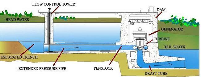
1 3- Hydropower The hydraulic power is one of the oldest energy sources of the mankind, namely for irrigation and industry. Nowadays, small hydro is one of the most valuable answers to the question of how to offer to isolated rural communities the benefits of electrification and the progress associated with it, as well as to improve the quality of life. The hydroelectric power plant utilises a natural or artificial fall of a river. The water flow energy is used to turn the wheel of a turbine and returns again to the river. This type of electricity production does not consume water, thus it is usually considered a renewable energy source. The flow will continue to fall downhill and the water will continue to be available as a resource for men and environment needs, thanks to the natural hydrologic cycle. The economic utilisation of renewable energies is now based on new technologies and on environmental protection techniques. Hydropower (large, small or micro), with its multiple advantages, as a decentralised, lowcost and reliable form of energy, is in the forefront of many developing countries to achieve energy selfsufficiecy. For environmental protection it must be considered, in each small hydro project, the ecological or reserved flow in order to protect downstream the wildlife habitats and to encourage or maintain the migration through fishpassages. It will be enhanced the main advantages to develop hydropower comparing with other electricity sources: It saves consumption of fossil, fuel, and firewood. It is self-sufficient without the need of fuel importation. It does not contribute for environment damages by resettlement, as it occurs with large dams and resvoirs. It can be a good private capital investment in developing or developed countries. It offers a decentralised electrification at a low running cost and with long life. Energy conversion and hydropower principles The theory of hydropower generation is based on the conversion of the hydraulic potential energy of a flow into electric energy, which corresponds to a differential net head. The energy of the flow is associated to the gravity energy through natural or artificially created topographic water falls in rivers or through hydraulic conveyance systems, composed by pressurised pipes or penstocks or by mixed hydraulic conveyance system composed by canal and penstocks.
2


3 The basic hydropower principle is based on the conversion of Ho or net head, the large part of the naturally dissipated head along a watercourse into mechanical and electrical energy: (the net head)
4 The net head of a hydropower plant built at section B can be created in quite a number of ways. Two fundamental ways are the following ones: to built a dam across a stream to increase the water level just above the powerplant; to divert part of the stream, with a minimum of headloss, to just above the powerplant built far away the dam. The net flow power Po and the corresponding energy Eo over an interval time t (s) of the hydropower plant will be respectively: The final useful head delivered to the electrical network is smaller than the available gross head: where is the global efficiency, resulting of the multiplication of partial efficiencies from the successive transport and conversion phases ( < 1). The hydroelectricity production is an energy conversion process, in which the water is the vehicle of transmission and transformation of the gravity potential energy into mechanical and electric energy by the turbine-generator set installed in the powerhouse. The water is led through pipes and/or canals to the turbine,
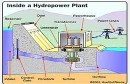
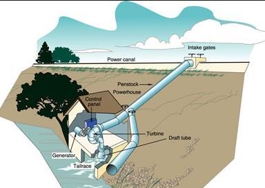
5 which turn the shaft of the generator to produce electric energy. From the powerhouse, after a convenient voltage transformation, transmission lines carry electricity out to communities or to the national grid. Classification of hydropower plants The classification of hydropower plants can be based on different factors: head: low (less than 50 m); medium (between 50 and 250 m); high (greater than 250 m); exploitation and storage: with daily (or seasonal) flow regulation (reservoir type); without flow regulation (run-of-the-river type); conveyance system: pressurised (penstock); mixed circuit (canal and penstock); powerhouse site: dam or diversion scheme; energy conversion mode: turbining or reversible pumping-turbining; type of turbines: impulse, reaction and reversible; installed power: micro (Pt < 100 kw); mini (100 kw < Pt < 500 kw); small (500 kw < Pt < 10 MW). The classification based on the power is very important because is an institutional and legislate reference. According to the mode of net head characterisation, the following main hydropower schemes can be identified: Dam scheme - The dam is used to concentrate the head, which raises the upstream water level. In this way, the powerhouse can be placed either at downstream incorporated inside the dam. Diversion scheme The utilisation of diversion structures, such as canals, tunnels or galleries or low-pressure conduits allows the head gain. A small dam can be used with long hydraulic circuit in order to obtain the net head at downstream end. Mixed scheme - A dam can partly raise the net head and a long hydraulic conveyance circuit will raise the other part. According to the mode of discharge exploitation, the following hydropower scheme types can be identified: Run-of-the-river scheme Power is generated without inflow regulation. It is a common scheme applied to mini or micro hydropower plants. Daily regulation scheme Power is generated according to the natural fluctuation of the daily demand, the water being stored in a regulating pond or small reservoir at offpeak times and discharging it at peak hours, resulting a bigger energy output comparatively to without regulation capability.
. Cascade scheme The cascade scheme is a typical exploitation of the river, in order to make the best use of the river falls.")
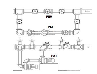
6 Seasonal regulation scheme This scheme is commonly applied in larger power plants, which needs a reservoir to store water in rainy season and discharge it in the dry season, enhancing a constant energy all year (normally it is not a common scheme in small power plants). Cascade scheme The cascade scheme is a typical exploitation of the river, in order to make the best use of the river falls. Power generation and different sector-users Water resources can be used in different ways to serve the society, taking into consideration all demands arising from different social and economic sector-users. Meanwhile, the exploitation and the utilisation of water resources aim to obtain the maximum benefit that should be controlled in order to reduce natural hazards and environmental impacts. Hydropower can be associated with different water uses: Power generation and water supply Reservoir Water supply system Pressure reducing valve Water distribution system Housings Daily demand Inlet control valve Generator Turbine Outlet Inlet Power generation and irrigation

7 Power generation and flood prevention Intakes Civil works are quite significant in Hydropower Plants (HP). There are different types of intakes with diversion flow to the turbine through the penstock: frontal, lateral, bottom drop and siphon type. For the two first types it is necessary to design the entrance shape in order to avoid separated zones of the flow and excessive head loss through wing walls. It is also necessary for all types to verify the minimum submergence in order to avoid vortex formation and, consequently, air entrance. The discharge control can be improved by special structures (e.g. narrow sections, weirs and gates or valves) depending upon if the flow is pressurised or of free surface type. The elevation of the water level can be controlled by a weir or by an inflatable or rubber dam or gate in order to create enough available head (Ho) to divert the desired discharge (Qo). Minimum submergence The vortex formation by insufficient intake submergence can induce air dragging or even solid material to the intake, reducing the turbine efficiency. The vortex development will depend on the geometry of the intake, the submergence and the approach flow velocity. The intake design criteria is based on the definition of minimum submergence in order to enable the guarantee of non-vortex formation, with air dragging into the hydraulic conveyance system.
8 d Two different types of flow approximation (i.e. symmetric and asymmetric) were considered and the following dimensionless equation is proposed: S C d V gd where: S is the submergence (m); d is the intake opening (m); V is the mean flow velocity at the inlet (m/s); g is the gravity acceleration (9.8 m/s 2 ) and C=1.7 (symmetric) or C=2.3 (asymmetric). S/d S/d=1+2,3 V/(gd) 0,5 0,5 S/d=2,3 V/(gd) Penino and Hecker Gordon S/d=1,7 V/(gd) 0, S/d=0,5(V /(gd) -1) Pressure pipe 0 0 0,5 1 1,5 2 V/(gd) 0,5 Different criteria for minimum submergence Bottom drop intake The bottom drop intake is largely used in SHP. Due to its simplicity it can be easily adapted to a low dam. The diverted discharge by this type of intake structure is a function of the rack characteristics, namely the opening degree or free area under non-submerged operational conditions. The design criteria must have into consideration the removing capacity of solid material by dragging. The rack is normally located at the top of the low dam, allowing the absorption of a discharge less or equal to the design one. Upstream Ho q Downstream Metalic rack qd Overflow spillway Collect channel Spillway Collect channel Low dam
9 length of the rack (m) 3,0 2,5 2,0 1,5 1,0 w idth = 2 m 0,5 w idth = 4 m w idth = 6 m 0,0 0,5 1,0 1,5 2,0 design discharge (m3/s) Estimation of the rack length as a function of the design discharge Friction head loss The friction loss along a canal or a penstock is expressed by H f J where L J = hydraulic gradient; L= length of the canal or the penstock (m). Reservoir Hydraulic grade line Total singular losses (curves, bends and valves) Gross head Net head Generator Conveyance system (low pressure pipe and penstock) Turbine V 2 /(2g) Tailrace Draft tube Hydraulic grade line of a hydro scheme equipped with a reaction turbine.
10 By assuming that the flow velocity is negligible in the reservoir, the gross and net heads are schematically defined in figure, for a reaction turbine with downstream draft tube. In this case the internal draft headlosses are considered in the turbine efficiency. - Pressure flow In closed pressurised pipes the flow is typically turbulent (Re > 2000), thus the Colebrook- White formula is advisable for friction head loss calculation. This formula requires an iterative method to solve the friction factor for each discharge value. The Moody diagram allows a graphical calculation. For this calculation it is necessary to know the mean velocity of the flow (U), the diameter of the pipe (D), the absolute roughness (k) and the kinematic viscosity of the water ( ). 1 f log 3.7 R e f where JD U 2g f 2 k D R UD e being f = Darcy-Weisbach factor; = relative roughness; R e = Reynolds number. In order to obtain the hydraulic gradient (J), it can be possible to establish the following iterative process based on any initial arbitrary value J n : J n1 2 U log 8 g D k 3.7D D g D J n 2 The value of the absolute roughness (k) depends on the material of the conduit. In Table 5.4 some k values are presented. Typical values of absolute roughness, k, for different type of materials material k (mm) cast iron - new - strongly rusty soldier steel - new - rusty concrete - rough - smooth
11 The friction head loss calculation can also be based on empirical formulae. In fact there are several empirical equations to estimate the hydraulic gradient (J), but they are only valid for some flow conditions. Two of the most popular empirical formulations are the Hazen-Williams and Gauckler-Manning-Strickler, which when expressed in SI units, are presented by the following equations: Q 0.849CS R Q K S R 2 J 0.63 J 0.54 where K and C depend on the pipe wall material; R is the hydraulic radius (R = D/4) and S is the pipe cross-section area. Typically coefficients of Gauckler-Manning-Strickler and Hazen-Williams formulas Materials K (m 1/3 /s) C (m 0.37 /s) steel cast iron concrete PVC Type of turbines The choice of standardised turbines for small hydro schemes depends upon the main system characteristics: net head, unit discharge and unit power. Hydraulic turbines convert hydropower energy into rotating mechanical energy. The main different types of turbines depend upon the way the water acts in the runner: a free jet at atmospheric pressure - impulse turbines; a pressurised flow - reaction turbines.

12 Resume of application range of standard turbines (based on several manufacturers data) Hydraulic Turbines H (m) Q (m 3 /s) P (kw) N s (r.p.m. ) (kw, m) Reaction Bulb Kaplan and propeller axial flow Francis with high specific speed - diagonal flow Francis with low specific speed radial flow Impulse Pelton <30 Turgo Cross-flow H (m) Q (m 3 /s) Specific speed Characteristic parameter N n s o H P 1.25 o
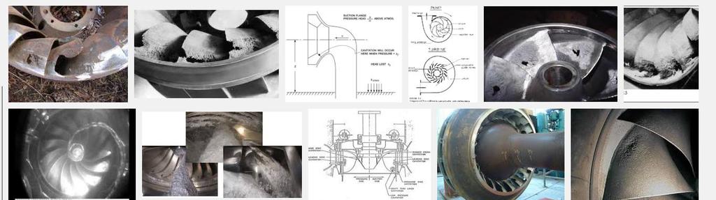
13 Variation of inlet triangle velocity with the specific speed (or runner shape). Reaction turbines Any reaction turbine is composed by the following elements: Spiral case - with decreasing cross section to downward direction to transform the pressure energy into kinetic one. Wicket gate (or guide vane) - guides the inlet of the flow into the runner, delivers it uniformly and controls the turbine discharge. Runner - radial or axial with or without movable blades. Draft tube - pipe with increasing cross section to downward direction. For reaction turbines, the flow is totally pressurized. Next step consists in calculation the runner position in order to avoid cavitation. The admissible suction head (h smax ) is defined by the difference between the characteristic runner section and the tailrace level. When the suction head is negative, the turbine operates in back-pressure. h s max p atm t v H o where
14 p atm = local barometric head (m); t v = vapour pressure (m); = dynamic depression coefficient or Thoma coefficient; H o = net head (m). Barometric head (absolute) and vapour pressure Altitude (m) p atm (m) Temperature (ºC) t v (m) Thoma coefficient ( ) gives the susceptibility to the cavitation occurrence of a reaction turbine. This parameter depends upon N s. Several curves have been proposed beeing one of them presented by Bureau of Reclamation, for reaction turbines with vertical shaft: N 1 s with N s in (m, kw) Shematic representation of suction turbine head (h s ). Out of normal operating conditions induce the cavitation phenomena occurrence. As a result of cavitation development, the performance of the turbine will be affected, since efficiency, appearance of vibrations and noise or blades erosion:
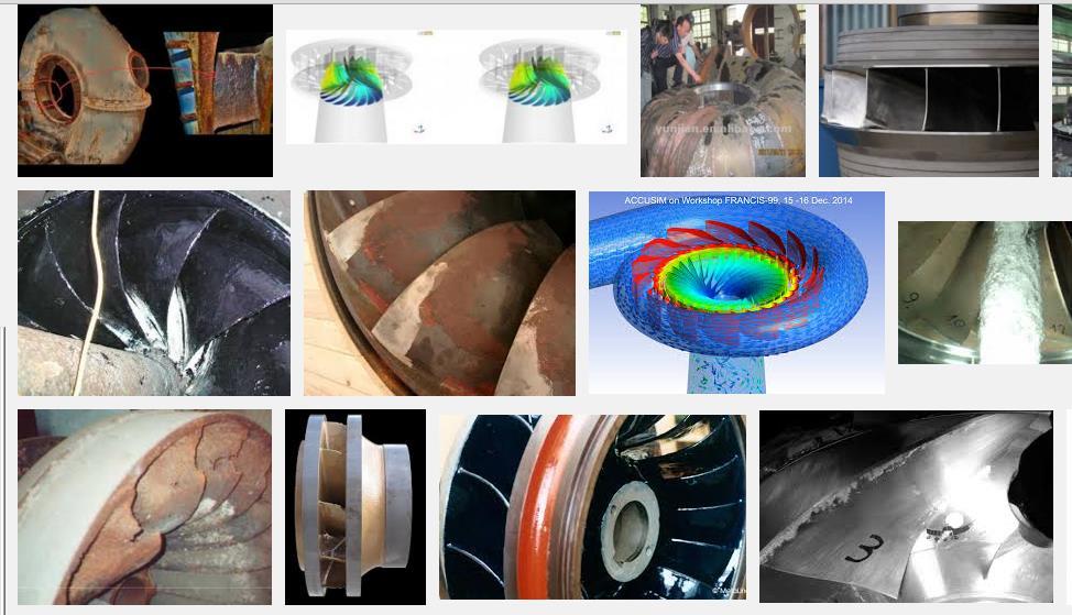
15
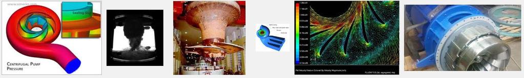
16 Characteristic Curves The operation of a turbine is defined by the characteristic curves that relate with the flow, head, power and torque for a rotational speed and wheel diameter. With this curves it s possible to trace equal efficiency lines, hill diagram. The main hydraulic characteristic is hydraulic power (P h ), that is obtain by using the specific weight fluid (γ), the discharge (Q), and the net head (H), and the mechanical power which is calculated by Torque (M), impeller rotational speed, fluid mass density (ρ), discharge, and free-vortex constant are used to calculate the engine or mechanical power (P e ), by using: The efficiency (η) is obtained using the electric power and the hydraulic power The theory of the hydraulic similarity consists in three essential laws: geometric similarity, kinematic similarity and dynamic similarity. They can be defined as: geometric similarity, the dimension of the turbine cannot be reduced to a smaller scale which can induce scale effects in the prototype; kinematic similarity, the triangle of speeds is equivalent in the inlet and outlet and dynamic similarity the polygon of forces must be similar both in the prototype as in the model. Figure - Turbine characteristic curves (KSB, 2005) Specific speed of a turbine gives the geometrical proportion of a similar turbine to a known turbine is defined by: N n s o H P 1.25 o In a turbine performance it must be defined two characteristic curves; the first corresponding to n=0, standstill curve, in which values of flow and head lower than this curve don t produce torque; and in the second, M=0, shows the values from which the torque isn t transmitted to the shaft (Figure).
17 Figure.. Torque curves Figure.. Efficiency curves for different rotational speeds


18 Figure.. Pressure results for the higher demand hour in PRV Figure Pressure results for the higher demand hour in Turbine (or PAT)
19
Hydroelectric power plants
 Hydroelectric power plants Hydroelectric power plants can drive from a water stream or accumulation reservoir. Run-of-river hydroelectric plants (those without accumulation reservoirs) built along a river
3. Design of Generation Equipment. 3.1 Turbine (1) Turbine Types Turbines are classified into two types according to their water energy utility:
 Turbine Types Turbines are classified into two types according to their water energy utility:") 3. Design of Generation Equipment 3.1 Turbine (1) Turbine Types Turbines are classified into two types according to their water energy utility: Impulse Turbines: all available water energy is converted
3. Design of Generation Equipment 3.1 Turbine (1) Turbine Types Turbines are classified into two types according to their water energy utility: Impulse Turbines: all available water energy is converted
SHRI RAMSWAROOP MEMORIAL COLLEGE OF ENGG. & MANAGEMENT
 B.Tech. [SEM VI(ME-61,62,63 & 64)] QUIZ TEST-1 Q-1). A jet strikes a smooth curved vane moving in the same direction as the jet and the jet get reversed in the direction. Show that the maximum efficiency
Renewable and Alternative Energies
 Department of Electrical and Energy Engineering This work is published under a license: Creative Commons BY-NC-SA 4.0 Contents Topic 1. Wind energy. Topic 2. Solar energy. Topic 3. Ocean energy.. Topic
Chapter 5 1. Hydraulic Turbines (Gorla & Khan, pp )
") Electronic Notes Chapter 5 1. Hydraulic Turbines (Gorla & Khan, pp.91 141) 1. Terminologies Related to A Hydropower Plant Hoover Dam generates more than 4 billion kilowatt-hours of electricity each year,
Electronic Notes Chapter 5 1. Hydraulic Turbines (Gorla & Khan, pp.91 141) 1. Terminologies Related to A Hydropower Plant Hoover Dam generates more than 4 billion kilowatt-hours of electricity each year,
Hydraulic Machines, K. Subramanya
 Hydraulic Machines power point presentation Slides has been adapted from Hydraulic Machines, K. Subramanya 2016-2017 Prepared by Dr. Assim Al-Daraje 1 Chapter (1 Part 1) Prepared by Dr. Assim Al-Daraje
A dimensional analysis for determining optimal discharge and penstock diameter in impulse and reaction water turbines
 A dimensional analysis for determining optimal discharge and penstock diameter in impulse and reaction water turbines Arturo S. Leon (Corresponding author). School of Civil and Construction Engineering,
Types of Hydropower Facilities
 Types of Hydropower Facilities 1 Impoundment Hydropower- uses a dam to store water. Water may be released either to meet changing electricity needs or to maintain a constant water level. 2 Run-of-River
Pumps, Turbines, and Pipe Networks, part 2. Ch 11 Young
 Pumps, Turbines, and Pipe Networks, part 2 Ch 11 Young Pump and Turbine Dimensional Analysis (11.5 Young) Say we want to replace turbines on the Hoover Dam Want to have a good design Essentially impossible
Determining Optimal Discharge and Optimal Penstock Diameter in Water Turbines
 Utah State University DigitalCommons@USU International Symposium on Hydraulic Structures Jun 9th, 1:30 PM - 3:30 PM Determining Optimal Discharge and Optimal Penstock Diameter in Water Turbines Arturo
2. (a) How do you classify water turbines? (b) Define and explain different efficiencies of a water turbine. [8+8]
![2. (a) How do you classify water turbines? (b) Define and explain different efficiencies of a water turbine. [8+8]](/thumbs/83/87300886.jpg "2. (a) How do you classify water turbines? (b) Define and explain different efficiencies of a water turbine. [8+8]") Code No: RR310302 Set No. 1 III B.Tech I Semester Supplementary Examinations, February 2007 HYDRAULIC MACHINERY AND SYSTEMS ( Common to Mechanical Engineering and Automobile Engineering) Time: 3 hours
Code No: RR310302 Set No. 1 III B.Tech I Semester Supplementary Examinations, February 2007 HYDRAULIC MACHINERY AND SYSTEMS ( Common to Mechanical Engineering and Automobile Engineering) Time: 3 hours
UNIT 5 HYDRAULIC MACHINES. Lecture-01
 1 UNIT 5 HYDRAULIC MACHINES Lecture-01 Turbines Hydraulic machines which convert hydraulic energy into mechanical energy. This mechanical energy is used to run electric generator which is directly coupled
UNIT I: UNIFORM FLOW PART B
 UNIT I: UNIFORM FLOW PART-A 1 Define open channel flow with example BT-1-1 2 Distinguish between open channel flow and pipe flow. BT-4-1 3 Compute the hydraulic mean depth of a small channel 1m wide, 0.5m
Small Hydro based energy generation
 Workshop on Capacity Development Program for Afghan Women (Clean Energy Access) Small Hydro based energy generation G Anil Head Small Hydro Power Dn., Energy Management Centre, Trivandrum 695017, Kerala,
 VALLIAMMAI ENGINEERING COLLEGE DEPARTMENT OF MECHANICAL ENGINEERING CE6451-FLUID MECHANICS AND MACHINERY UNIT- I: FLUID PROPERTIES AND FLOW CHARACTERISTICS PART-A 1. Find the surface tension in a soap
Code No: R Set No. 1
 Code No: R050210201 Set No. 1 II B.Tech I Semester Regular Examinations, November 2006 FLUID MECHANICS & HYDRAULIC MACHINERY (Electrical & Electronic Engineering) Time: 3 hours Max Marks: 80 Answer any
 DEPARTMENT OF CIVIL ENGINEERING CE6403/ APPLIED HYDRAULIC ENGINEERING QUESTION BANK TWO MARKS UNIT I UNIFORM FLOW 1. Differentiate open channel flow from pipe flow. 2. What is specific energy and is the
A techno-economical view on energy losses at hydropower dams (case study of Karun III Dam and Hydropower Plant)
") Computational Methods in Multiphase Flow VI 253 A techno-economical view on energy losses at hydropower dams (case study of Karun III Dam and Hydropower Plant) M. Jorabloo 1, M. Abdolahpour 2, R. Roshan
Computational Methods in Multiphase Flow VI 253 A techno-economical view on energy losses at hydropower dams (case study of Karun III Dam and Hydropower Plant) M. Jorabloo 1, M. Abdolahpour 2, R. Roshan
INCOMPRESSIBLE FLOW TURBOMACHINES Design, Selection, Applications,
 INCOMPRESSIBLE FLOW TURBOMACHINES Design, Selection, Applications, George F. Round Professor Emeritus McMaster University Hamilton, Ontario Canada ELSEVIER BUTTERWORTH HEINEMANN Amsterdam Boston Heidelberg
Chapter 5 1. Hydraulic Pumps (pp , Gorla & Khan; Wiki)
") Chapter 5 1. Hydraulic Pumps (pp. 47 90, Gorla & Khan; Wiki) 1. Two Basic Categories of Pumps Positive Displacement (PD) Pumps A positive displacement pump causes a fluid to move by trapping a fixed amount
Chapter 5 1. Hydraulic Pumps (pp. 47 90, Gorla & Khan; Wiki) 1. Two Basic Categories of Pumps Positive Displacement (PD) Pumps A positive displacement pump causes a fluid to move by trapping a fixed amount
Alpha College of Engineering
 Alpha College of Engineering Department of Mechanical Engineering TURBO MACHINE (10ME56) QUESTION BANK PART-A UNIT-1 1. Define a turbomahcine. Write a schematic diagram showing principal parts of a turbo
(a) the inlet and exit vane angles, (b) work done (c) Efficiency of the system. [16]
![(a) the inlet and exit vane angles, (b) work done (c) Efficiency of the system. [16]](/thumbs/81/82633878.jpg "(a) the inlet and exit vane angles, (b) work done (c) Efficiency of the system. [16]") Code No: R05310302 Set No. 1 III B.Tech I Semester Regular Examinations, November 2007 HYDRAULIC MACHINERY AND SYSTEMS ( Common to Mechanical Engineering and Automobile Engineering) Time: 3 hours Max Marks:
Code No: R05310302 Set No. 1 III B.Tech I Semester Regular Examinations, November 2007 HYDRAULIC MACHINERY AND SYSTEMS ( Common to Mechanical Engineering and Automobile Engineering) Time: 3 hours Max Marks:
= Guide angle = angle between direction of jet and direction of motion of vane/bucket.
 GEC223: FLUID MECHANICS MODULE 4: HYDROPOWER SYSTEMS TOPIC: IMPULSE TURBINES-PELTON WHEEL DEPARTMENT OF CIVIL ENGINEERING, LANDMARK UNIVERSITY, KWARA STATE, NIGERIA CONSTRUCTION AND WORKING OF A PELTON
Download From:
 Fluid Mechanics 1. A single acting reciprocating pump, running at 60 r.p.m, delivers 0.01 m2/sec of water. The area of the piston is0.05m2 and stroke length is 40 cm. Then theoretical discharge of the
Hydropower retrofitted onto existing water infrastructure assets
 Hydropower retrofitted onto existing water infrastructure assets Marco van Dijk Lecturer and Principal Researcher University of Pretoria / Water Research Commission South Africa Presentation Layout How
T.E. (Mech., Mech. S/W) (Semester II) Examination, 2011 TURBOMACHINES (New) (2008 Pattern)
 (Semester II) Examination, 2011 TURBOMACHINES (New) (2008 Pattern)") *4063218* [4063] 218 T.E. (Mech., Mech. S/W) (Semester II) Examination, 2011 TURBOMACHINES (New) (2008 Pattern) Time : 3 Hours Marks : 100 Instructions : 1) Answer any three questions from each Section.
*4063218* [4063] 218 T.E. (Mech., Mech. S/W) (Semester II) Examination, 2011 TURBOMACHINES (New) (2008 Pattern) Time : 3 Hours Marks : 100 Instructions : 1) Answer any three questions from each Section.
RRB TECHNICAL EXAM QUESTIONS
 RRB TECHNICAL EXAM QUESTIONS Fluid Mechanics 1. A single acting reciprocating pump, running at 60 r.p.m, delivers 0.01 m2/sec of water. The area of the piston is0.05m2 and stroke length is 40 cm. Then
Level 6 Graduate Diploma in Engineering Hydraulics and hydrology
 910-103 Level 6 Graduate Diploma in Engineering Hydraulics and hydrology Sample Paper You should have the following for this examination one answer book ordinary graph paper pen, pencil, ruler Work sheet
HYDRAULIC TURBINES GATE MASTER S ACADEMY. Hydraulic turbines
 8 YDRAULIC TURBIES 0. Ans : (a & d) ydraulic machine is a device which converts fluid energy into mechanical energy is called turbine. ydraulic machine is a device which converts mechanical energy into
SEES 503 SUSTAINABLE WATER RESOURCES HYDROELECTRIC POWER. Assist. Prof. Dr. Bertuğ Akıntuğ
 SEES 503 SUSTAINABLE WATER RESOURCES HYDROELECTRIC POWER Assist. Prof. Dr. Bertuğ Akıntuğ Civil Engineering Program Middle East Technical University Northern Cyprus Campus SEES 503 Sustainable Water Resources
Fluid Mechanics. The Energy Equation [7] Dr. Mohammad N. Almasri
![Fluid Mechanics. The Energy Equation [7] Dr. Mohammad N. Almasri](/thumbs/77/76088370.jpg "Fluid Mechanics. The Energy Equation [7] Dr. Mohammad N. Almasri") 1 Fluid Mechanics The Energy Equation [7] Dr. Mohammad N. Almasri http://sites.google.com/site/mohammadnablus/home 2 Introduction There are various types of devices and components that are utilized in
1 Fluid Mechanics The Energy Equation [7] Dr. Mohammad N. Almasri http://sites.google.com/site/mohammadnablus/home 2 Introduction There are various types of devices and components that are utilized in
Pumps, Turbines, and Pipe Networks. Ch 11 Young
 Pumps, Turbines, and Pipe Networks Ch 11 Young Chapter Topics Types of pumps and turbines Moment of momentum review Pump and turbine theory Energy and power Pump selection Pump-pipe networks Use of pipe
Francis Turbine Upgrade for the Lushui Generating Station by Using Computational Fluid Dynamics - A Case Study
 Francis Turbine Upgrade for the Lushui Generating Station by Using Computational Fluid Dynamics - A Case Study J. Huang, Ph.D., Hydraulic Energy Group, Sustainable Buildings and Communities, CANMET Energy
IMPACT AND PUNCTURING OF JARI TUNNEL AND ENLARGEMENT OF EXISTING TAPPINGS FOR ADDITIONAL WATER SUPPLY AND POWER GENERATION
 117 Paper No. 738 IMPACT AND PUNCTURING OF JARI TUNNEL AND ENLARGEMENT OF EXISTING TAPPINGS FOR ADDITIONAL WATER SUPPLY AND POWER GENERATION JAVED MUNIR, SYED ABBAS ALI, IRFAN MAHMOOD 118 Javed Munir,
EFFICIENCY ANALYSES FOR SMALL HYDRO POWER PLANT WITH FRANCIS TURBINE
 EFFICIENCY ANALYSES FOR SMALL HYDRO POWER PLANT WITH FRANCIS TURBINE Xhevat Berisha 1, Bukurije Hoxha 2 and Drilon Meha 3 1,2,3 Department of Thermotechnics and Renewable Energy, Faculty of Mechanical
Tutorial letter 101/0/2016
 Tutorial letter 101/0/2016 Hydraulic Machines III (Theory) FMA3602 Year Module Department of Mechanical and Industrial Engineering IMPORTANT INFORMATION: This tutorial letter contains important information
CH 6.docx CH 1.docx CH 2.docx CH 3.docx CH 4.docx CH 5.docx
 CH 6.docx CH 1.docx CH 2.docx CH 3.docx CH 4.docx CH 5.docx CH 6 MISCELLANEOUS MACHINES THEORY (1) With neat sketch explain construction and working of hydraulic torque Convertor [643] (2) Write short
Physical models application of flow analysis in regulated reservoir dams
 River Basin Management III 15 Physical models application of flow analysis in regulated reservoir dams M. R. M. Tabatabai 1, S. Faghihirad 2 & M. Kolahdoozan 3 1 Water Engineering Department, Power and
DESIGN OF A PELTON WHEEL TURBINE FOR A MICRO HYDRO POWER PLANT
 DESIGN OF A PELTON WHEEL TURBINE FOR A MICRO HYDRO POWER PLANT Manjunatha N 1, Kuldeepak Kumar 2, Dr. Thammaih Gowda 3 1, 2 Assistant Professor, Dept. of Mechanical Engineering, N.D.R.K.I.T, Hassan, Karnataka
Approach for Cost Determination of Electro-Mechanical Equipment in RoR SHP Projects
 Smart Grid and Renewable Energy, 2011, 2, 63-67 doi:10.4236/sgre.2011.22008 Published Online May 2011 (http://www.scirp.org/journal/sgre) 63 Approach for Cost Determination of Electro-Mechanical Equipment
Clean energy saving: applied research into Etna s water supply systems in Catania, Italy
 Energy and Sustainability 35 Clean energy saving: applied research into Etna s water supply systems in Catania, Italy F. Patania, A. Gagliano, F. Nocera & I. Pellegrino Energy and Environment Division
Hydropower. See the notes in Compedu Source: Marianne KTH
 Hydropower See the notes in Compedu http://www.energy.kth.se/compedu/webcompedu/index.html Source: Marianne Salomon @ KTH Global Renewable Energy Source: IEA Worldwide Hydropower Source: IEA Hydropower
Hybrid Hydroelectric Power Plant : The Ultimate Technology For Electricity Generation
 Hybrid Hydroelectric Power Plant : The Ultimate Technology For Electricity Generation Prof. Nilesh P. Patil. 1*, Prof. Dr. V. S. Patil. 2 1 - Asst. Professor (Chemical Engineering), University Institute
Energy Resources. Assosciate Professor
 Energy Resources Dr. Fahad Noor Assosciate Professor f.noor@uet.edu.pk Engr. Adnan Qamar Lecturer adnan@uet.edu.pk Hydro Power Hydropower energy is ultimately derived from the sun, which drives the water
00046 Term-End Examination June, 2015
 No. of Printed Pages : 5 BIME-013 B.Tech. - VIEP - MECHANICAL ENGINEERING (BTMEVI) 00046 Term-End Examination June, 2015 BIME-013 : TURBO MACHINES Time : 3 hours Maximum Marks : 70 Note : Answer any five
CE 6403 APPLIED HYDRAULIC ENGINEERING (REG -2013)
") CE 6403 APPLIED HYDRAULIC ENGINEERING (REG -2013) CE 6403 APPLIED HYDRAULIC ENGINNERING Page 1 CE 6403 APPLIED HYDRAULIC ENGINEERING 1.UNIT I UNIFORM FLOW SYLLABUS Definition and differences between pipe
CE 6403 APPLIED HYDRAULIC ENGINEERING (REG -2013) CE 6403 APPLIED HYDRAULIC ENGINNERING Page 1 CE 6403 APPLIED HYDRAULIC ENGINEERING 1.UNIT I UNIFORM FLOW SYLLABUS Definition and differences between pipe
Estimating Hydropower Potential of an Ungauged Stream
 Estimating Hydropower Potential of an Ungauged Stream Umaru Garba Wali Water Resources and Environmental Management Programme, Department of Civil Engineering, School of Engineering, College of Science
[4163] T.E. (Mechanical) TURBO MACHINES (2008 Pattern) (Common to Mech. S/W) (Sem. - II)
![[4163] T.E. (Mechanical) TURBO MACHINES (2008 Pattern) (Common to Mech. S/W) (Sem. - II)](/thumbs/77/76045894.jpg "[4163] T.E. (Mechanical) TURBO MACHINES (2008 Pattern) (Common to Mech. S/W) (Sem. - II)") Total No. of Questions : 12] P1061 SEAT No. : [Total No. of Pages : 7 [4163] - 218 T.E. (Mechanical) TURBO MACHINES (2008 Pattern) (Common to Mech. S/W) (Sem. - II) Time : 3 Hours] [Max. Marks :100 Instructions
Total No. of Questions : 12] P1061 SEAT No. : [Total No. of Pages : 7 [4163] - 218 T.E. (Mechanical) TURBO MACHINES (2008 Pattern) (Common to Mech. S/W) (Sem. - II) Time : 3 Hours] [Max. Marks :100 Instructions
FINAL Examination Paper (COVER PAGE) Programme : Diploma in Mechanical Engineering. Time : 8.00 am am Reading Time : 10 Minutes
 Programme : Diploma in Mechanical Engineering. Time : 8.00 am am Reading Time : 10 Minutes") Session : May 2013 FINAL Examination Paper (COVER PAGE) Programme : Diploma in Mechanical Engineering Course : EGR2180 : FLUIDS MECHANICS 2 Date of Examination : July 25, 2013 Time : 8.00 am 10.10 am Reading
Session : May 2013 FINAL Examination Paper (COVER PAGE) Programme : Diploma in Mechanical Engineering Course : EGR2180 : FLUIDS MECHANICS 2 Date of Examination : July 25, 2013 Time : 8.00 am 10.10 am Reading
COMPUTER APPLICATIONS HYDRAULIC ENGINEERING
 - 7535 COMPUTER APPLICATIONS IN HYDRAULIC ENGINEERING Connecting Theory to Practice Fifth Edition HAESTAD PRESS Table of Contents Revision History Foreword CHAPTER 1 BASIC HYDRAULIC PRINCIPLES 1 1.1 General
ErcoleMareliGroup. GreenPowerGenera on HYDROPOWERPLANTTURBINES
 ErcoleMareliGroup GreenPowerGenera on HYDROPOWERPLANTTURBINES SMALL SCALE HYDRO POWER PLANTS Ercole Marelli Power offers a wide range of solutions for hydropower applications. EMP employs new design techniques,
Turbo Machines Pumps and Turbines ME 268
 Turbo Machines Pumps and Turbines ME 268 Turbo Machines Turbo machines are dynamic fluid machines that either extract energy from a fluid (turbine) or add energy to a fluid (pump) as a result of dynamic
i. Weight density :- It is a ratio of weight to volume. unit 01 Marks Kinematic viscosity :- It is a ratio of dynamic viscosity to mass density.
 Important Instructions to examiners: 1) The answers should be examined by key words and not as word-to-word as given in the model answer scheme. 2) The model answer and the answer written by candidate
From Wikipedia, the free encyclopedia
 1 of 6 1/3/2017 2:26 PM From Wikipedia, the free encyclopedia Micro hydro is a type of hydroelectric power that typically produces from 5 kw to 100 kw of electricity using the natural flow of water. Installations
MICRO-HYDRO POWER. Technical
 MICRO-HYDRO POWER Introduction Water power can be harnessed in many ways; tidal flows can be utilised to produce power by building a barrage across an estuary and releasing water in a controlled manner
CE2253 APPLIED HYDRAULIC ENGINEERING (FOR IV - SEMESTER)
") CE2253 APPLIED HYDRAULIC ENGINEERING (FOR IV - SEMESTER) UNIT I to V QUESTION BANK Prepared by, M.SUGANYA. B.E., LECTURER / CIVIL DEPARTMENT OF CIVIL ENGINEERING CE2253 APPLIED HYDRAULIC ENGINEERING UNIT
CE2253 APPLIED HYDRAULIC ENGINEERING (FOR IV - SEMESTER) UNIT I to V QUESTION BANK Prepared by, M.SUGANYA. B.E., LECTURER / CIVIL DEPARTMENT OF CIVIL ENGINEERING CE2253 APPLIED HYDRAULIC ENGINEERING UNIT
Adjustable speed operation of a hydropower plant associated to an irrigation reservoir
 Adjustable speed operation of a hydropower plant associated to an irrigation reservoir Juan I. Perez, Jose R. Wilhelmi, Luis Maroto Department of Hydraulic and Energy Engineering, ETS de Ingenieros de
2/25, Ansari Road, Darya Ganj, New Delhi
 B.E.(Mechanical), M.I.E(India) M.B.M. Engineering College, Jodhpur M.E. (Structural), Delhi University B.E.(Civil) M.B.M. Engineering College, Jodhpur (AN ISO 9001:2008 Certified Company) VAYU EDUCATION
Code No: R Set No. 1
 Code No: R05310302 Set No. 1 III B.Tech I Semester Regular Examinations, November 2008 HYDRAULIC MACHINERY AND SYSTEMS ( Common to Mechanical Engineering and Automobile Engineering) Time: 3 hours Max Marks:
STATE UNIVERSITY OF NEW YORK COLLEGE OF TECHNOLOGY CANTON, NEW YORK COURSE OUTLINE CONS 322 HYDRAULICS
 STATE UNIVERSITY OF NEW YORK COLLEGE OF TECHNOLOGY CANTON, NEW YORK COURSE OUTLINE CONS 322 HYDRAULICS Prepared By: Joseph Reilly CANINO SCHOOL OF ENGINEERING TECHNOLOGY CIVIL AND CONSTRUCTION TECHNOLOGY
11/10/2009. Lake Uist - BAKER PT. Distributor from bore to penstocks Lowest level in draft tube FSL Top of surge tank.
 Parametric Analysis of Pump- Turbine Sites J. L. Gordon, P. Eng. Fellow CSCE 190.0 FSL 203.6 Top of surge tank. Lake Uist - BAKER PT 193.0 Deck El. 2120.6 Surge tank required? Yes 169.5 Bottom of surge
Unit 1. FLUID AND FLUID PROPERTIES.
 3 rd MECHANICAL ASSIGNMENT FOR FLUID MECHANICS AND HYDRAULIC MACHINES SUBJECT CODE: 3331903 Unit 1. FLUID AND FLUID PROPERTIES. (1) What is fluid? State and explain types of fluid. (2) Define the following
Chapter (2) Prepared by Dr. Assim Al-Daraje
 Prepared by Dr. Assim Al-Daraje") Chapter (2) Prepared by Dr. Assim Al-Daraje 1 INTRODUCTION The Pelton turbine is ideal for high-head and low-discharge situations. The number of jets in a turbine is usually one. However, where additional
Chapter (2) Prepared by Dr. Assim Al-Daraje 1 INTRODUCTION The Pelton turbine is ideal for high-head and low-discharge situations. The number of jets in a turbine is usually one. However, where additional
AC-TEC THE COMPANY. Kaplan, Francis, Pelton, Cross Flow and Mini Turbines.
 AC-TEC THE COMPANY Kaplan, Francis, Pelton, Cross Flow and Mini Turbines. The family business AC-TEC is specialized in the production of small hydro power plants for many decades and manufactures customized
DHANALAKSHMI COLLEGE OF ENGINEERING, CHENNAI DEPARTMENT OF CIVIL ENGINEERING CE 6403 APPLIED HYDRAULIC ENGINEERING UNIT I: UNIFORM FLOW
 DHANALAKSHMI COLLEGE OF ENGINEERING, CHENNAI DEPARTMENT OF CIVIL ENGINEERING CE 6403 APPLIED HYDRAULIC ENGINEERING UNIT I: UNIFORM FLOW PART A (2 marks) 1. Distinguish between open channel flow and conduit
WATER SUPPLY ENGINEERING
 1 WATER SUPPLY ENGINEERING (RESERVOIRS AND DISTRIBUTION SYSTEM) Compiled and Prepared By: Abhash Acharya Central Campus, Pulchowk 2 7.1 Systems of Supply: 7.1.1 Continuous System: The system of supply
Energy supply with hydropower
 Energy supply with hydropower University of Kassel, Department of Hydraulic Engineering g and Water Resources Management Prof. Dr.-Ing. Stephan Theobald www.renewables-made-in-germany.com 08.03.2016 in
Intro to. Part 1: Systems Overview. Dan New
 Intro to Hydropower Part 1: Systems Overview Dan New 2004 Dan New Hydropower is based on simple concepts. Moving water turns a turbine, the turbine spins a generator, and electricity is produced. Many
SMALL HYDROPOWER PLANTS
 G U I D E L I N E S F O R D E S I G N O F SMALL HYDROPOWER PLANTS Editor Helena RAMOS TECHNICAL CARD Copyright c 2000. Published in 2000 through WREAN (Western Regional Energy Agency & Network) and DED
Fig Micro-hydro s economy of scale ( based on data in 1985)
") CHAPTER 1 INTRODUCTION 1.1 Purpose of the Manual for Micro-Hydro Development Micro-Hydroelectric Power, called as a Micro-Hydro, usually does not supply electricity to the national grid. They are used
CHAPTER 1 INTRODUCTION 1.1 Purpose of the Manual for Micro-Hydro Development Micro-Hydroelectric Power, called as a Micro-Hydro, usually does not supply electricity to the national grid. They are used
Micro Hydro In a Municipal Water and Power System
 Micro Hydro In a Municipal Water and Power System By: Chris Thompson Colorado Springs Utilities Hydro Electric Power Plant Operator and Micro Hydro Consultant Presented at: The 2006 APPA Engineering and
UNIT I FLUID PROPERTIES AND FLUID STATICS
 SIDDHARTH GROUP OF INSTITUTIONS :: PUTTUR Siddharth Nagar, Narayanavanam Road 517583 QUESTION BANK (DESCRIPTIVE) Subject with Code : FM & HM (16CE112) Year & Sem: II-B.Tech & I-Sem Course & Branch: B.Tech
SCHOOL OF COMPUTING, ENGINEERING AND MATHEMATICS SEMESTER 1 EXAMINATIONS 2014/2015 ME257. Fluid Dynamics. Answer FOUR out of SIX questions
 s SCHOOL OF COMPUTING, ENGINEERING AND MATHEMATICS SEMESTER 1 EXAMINATIONS 2014/2015 ME257 Fluid Dynamics Time allowed: TWO hours Answer: Answer FOUR out of SIX questions Items permitted: Any approved
INVESTIGATIONS ON PERFORMANCE OF A SAVONIUS HYDROKINETIC TURBINE
 INVESTIGATIONS ON PERFORMANCE OF A SAVONIUS HYDROKINETIC TURBINE Ph.D. THESIS by ANUJ KUMAR ALTERNATE HYDRO ENERGY CENTRE INDIAN INSTITUTE OF TECHNOLOGY ROORKEE ROORKEE-247667 (INDIA) AUGUST, 2017 INVESTIGATIONS
Experiment No.2 STUDY & TRIAL ON A FRANCIS TURBINE & PLOTTING OF MAIN /OPERATING CHARACTERISTICS.
 Experiment No.2 STUDY & TRIAL ON A FRANCIS TURBINE & PLOTTING OF MAIN /OPERATING CHARACTERISTICS. Name of the student: Roll No: Date of Performance : Date of Submission Marks Scored: Signature of Staff
HydroHelp 5 AN EXCEL PROGRAM DEVELOPED FOR PRE-FEASIBILITY ASSESSMENT PUMP-STORAGE HYDROELECTRIC SITES. J. L. GORDON P.Eng.
 HydroHelp 5 AN EXCEL PROGRAM DEVELOPED FOR PRE-FEASIBILITY ASSESSMENT OF PUMP-STORAGE HYDROELECTRIC SITES BY J. L. GORDON P.Eng. January, 2009 HydroHelp 5 for pump-turbine sites. A continuation of the
STANDARDS / MANUALS / GUIDELINES FOR SMALL HYDRO DEVELOPMENT
 Draft May 19, 2008 STANDARDS / MANUALS / GUIDELINES FOR SMALL HYDRO DEVELOPMENT SPONSOR: MINISTRY OF NEW AND RENEWABLE ENERGY GOVERNMENT OF INDIA ELECTRO MECHANICAL GUIDE FOR SELECTION OF TURBINE AND GOVERNING
CE6403 APPLIED HYDRAULIC ENGINEERING UNIT 1 UNIFORM FLOW
 CE6403 APPLIED HYDRAULIC ENGINEERING UNIT 1 UNIFORM FLOW Definition and differences between pipe flow and open channel flow - Types of Flow - Properties of open channel - Fundamental equations - Velocity
Turbines II: Hydro and Wind GEOS 24705/ ENST 24705
 Turbines II: Hydro and Wind GEOS 24705/ ENST 24705 Copyright E. Moyer 2012 Dam Hydropower Water is guided to the turbine via a penstock that controls flow and pressure Image: Xeneca Corp. 3 main dam hydro
Design and Development of Pico-hydro Generation System for Energy Storage Using Consuming Water Distributed to Houses
 Design and Development of Pico-hydro Generation System for Energy Storage Using Consuming Water Distributed to Houses H. Zainuddin, M. S. Yahaya, J. M. Lazi, M. F. M. Basar and Z. Ibrahim Abstract This
Annex A Turbine Passage Modification Plan
 Appendix D Annex A Turbine Passage Modification Plan Table A1 Model Turbine Performance Table A2 Model Turbine Performance Table A3 Model Turbine Performance Table A4 Model Turbine Performance Table A5
Fabrication and Installation of Mini Kaplan Turbine
 Fabrication and Installation of Mini Kaplan Turbine Sasidhar Gurugubelli 1, Chandu Gummalla 2, Prasanth Gunipalli 3, Venkatesh balasa 4, Md Shafi 5 1 Assistant professor, lendi institute of engineering
ZHORIF IKMAL BIN ZAHARI MOHAMAD AKMAL BIN ISHAK NUR AZIMAH BINTI AHMAD KAMAL NURUL FATIHA SHAHIRA BINTI MOHD ZULKIFLI
 Persatuan Pelajar Kejuruteraan Mekanikal Universiti Teknologi Malaysia Kuala Lumpur ZHORIF IKMAL BIN ZAHARI MOHAMAD AKMAL BIN ISHAK NUR AZIMAH BINTI AHMAD KAMAL NURUL FATIHA SHAHIRA BINTI MOHD ZULKIFLI
The Islamic University of Gaza- Environmental Engineering Department Networks Design and Pumping Stations EENV Lecture 9: Pumping Station
 The Islamic University of Gaza- Environmental Engineering Department Networks Design and Pumping Stations EENV 5315 Lecture 9: Pumping Station Water supply pumping system Pumps are used to increase the
EXPERIMENTAL AND NUMERICAL INVESTIGATION OF CENTRIFUGAL PUMP PERFORMANCE IN REVERSE MODE`
 EXPERIMENTAL AND NUMERICAL INVESTIGATION OF CENTRIFUGAL PUMP PERFORMANCE IN REVERSE MODE` Jayendra B Patel 1, R.N.Mevada 2, Dheeraj Sardana 3, Vinod P. Rajput 4 1, 2, 3,4 Department of Mechanical Engineering,
Design and Simulation of Very Low Head Axial Hydraulic Turbine with Variation of Swirl Velocity Criterion
 International Journal of Fluid Machinery and Systems DOI: http://dx.doi.org/10.5293/ijfms.2014.7.2.068 Vol. 7, No. 2, April-June 2014 ISSN (Online): 1882-9554 Original Paper (Invited) Design and Simulation
Appendix 6: Choosing the Right Turbine
 Appendix 6: Choosing the Right Turbine A graphical representation of the power output of the hydro turbines in our product line is shown below. Once you have determined your site s head, flow, and your
Terry McGuire & Phil Leigh. New Mills Hydro. Heron Corn Mill. (case study)
") Terry McGuire & Phil Leigh New Mills Hydro p.leigh@lancaster.ac.uk nht@newmillshydro.com Heron Corn Mill (case study) Heron Corn Mill, Beetham Beetham, Cumbria Heron Corn Mill Historical water use in Cumbria
Terry McGuire & Phil Leigh New Mills Hydro p.leigh@lancaster.ac.uk nht@newmillshydro.com Heron Corn Mill (case study) Heron Corn Mill, Beetham Beetham, Cumbria Heron Corn Mill Historical water use in Cumbria
Hydro Electric Power (Hydel Power)
") Operating Principle Hydro Electric Power (Hydel Power) Hydro-electric power is generated by the flow of water through turbine, turning the blades of the turbine. A generator shaft connected to this turbine
Operating Principle Hydro Electric Power (Hydel Power) Hydro-electric power is generated by the flow of water through turbine, turning the blades of the turbine. A generator shaft connected to this turbine
WEST POINT PERTINENT DATA. GENERAL Location (damsite) Troup County GA, Chambers County AL, miles above mouth of Chattahoochee River
 Troup County GA, Chambers County AL, miles above mouth of Chattahoochee River") WEST POINT PERTINENT DATA GENERAL Location (damsite) Troup County GA, Chambers County AL, miles above mouth of Chattahoochee River 201.4 Drainage area, Buford Dam to West Point Dam, square miles 2,406
WEST POINT PERTINENT DATA GENERAL Location (damsite) Troup County GA, Chambers County AL, miles above mouth of Chattahoochee River 201.4 Drainage area, Buford Dam to West Point Dam, square miles 2,406
Pure Axial Flow with Aerofoil Theory.
 Kaplan Turbine P M V Subbarao Professor Mechanical Engineering Department Pure Axial Flow with Aerofoil Theory. The Fast Machine for A Low Head U b V wi V ri V fi V ai U b Vwi V fi V ai V ri Kaplan Turbine
HYDRO-QUÉBEC S CONTINUOUS FLOW MEASUREMENT SYSTEM: DEVELOPMENT OF AN INDUSTRIAL PROTOTYPE
 HYDRO-QUÉBEC S CONTINUOUS FLOW MEASUREMENT SYSTEM: DEVELOPMENT OF AN INDUSTRIAL PROTOTYPE M Bouchard Dostie 1, G Proulx 1, J Nicolle 2 and L Martell 2 1 Essais Spéciaux de Production, Hydro Québec, 5655
PICO HYDRO POWER GENERATION: RENEWABLE ENERGY TECHNOLOGY FOR RURAL ELECTRIFICATION
 PICO HYDRO POWER GENERATION: RENEWABLE ENERGY TECHNOLOGY FOR RURAL ELECTRIFICATION Dr. S.K. Dave 1, Ashokkumar A. Parmar 2, Ankit P. Shah 3, Nikhil M. Vyas 4 Lecturer (SG), Applied Mechanics Dept. & I/C
R13. (12M) efficiency.
 efficiency.") SET - 1 II B. Tech I Semester Regular/Supplementary Examinations, Oct/Nov - 2016 THERMAL AND HYDRO PRIME MOVERS (Electrical and Electronics Engineering) Time: 3 hours Max. Marks: 70 Note: 1. Question Paper
SET - 1 II B. Tech I Semester Regular/Supplementary Examinations, Oct/Nov - 2016 THERMAL AND HYDRO PRIME MOVERS (Electrical and Electronics Engineering) Time: 3 hours Max. Marks: 70 Note: 1. Question Paper
MICRO-HYDRO INSTALLATION SIZING Jacques Chaurette eng. January 17, 2008
 MICRO-HYDRO INSTALLATION SIZING Jacques Chaurette eng. January 17, 2008 www.lightmypump.com A friend of mine asked me to help size a micro-hydro installation that he was thinking of installing at his cottage.
Water intake structures for hydropower
 Water intake structures for hydropower Dritan Bratko1, Alban Doko 1 Department of Hydraulic and Hydrotechnic, Universiteti Politeknik i Tiranes, Albania Department of Hydraulic and Hydrotechnic, Universiteti
Chakachamna Hydro. AEA Geothermal Conference
 Chakachamna Hydro AEA Geothermal Conference August 2007 Chakachamna Hydro 300+ MW hydro opportunity identified Preliminary FERC License application filed in May 2006 Initial scoping/informational meetings
2 FINDING OF THE POTENTIAL SITES
 EXECUTIVE SUMMARY 1 Background S-1 2 User of Manual S-1 3 Applicable Range of Micro-hydro power in the Indonesia S-2 4 How to use this Manual S-2 Chapter 1 INTRODUCTION 1-1 1.1 Purpose of the Manual
Modeling and Simulation of Irrigation Canals with Hydro Turbines
 Modeling and Simulation of Irrigation Canals with Hydro Turbines S Mohan Kumar Scientist, Department of Research, ABB Global Industries and Services Ltd Bangalore, India * mohan.s.kumar@in.abb.com (corresponding