Solar PV System Code Compliance Best Practices, 2017 NEC Updates, and Opportunities for Improvement
|
|
|
- Madlyn Stokes
- 6 years ago
- Views:
Transcription


1 Solar PV System Code Compliance Best Practices, 2017 NEC Updates, and Opportunities for Improvement MassCEC Webinar April 2017 Presented by: Matt Piantedosi Manager of Solar Field Operations The Cadmus Group

2 Table of Contents Introduction About The Cadmus Group PV Inspections and Score Classifications PV Interconnection Array Grounding and Bonding Wiring Methods Microinverters Modules Roof Penetrations PV System Labeling String/Central Inverters Grounding Electrode System Inverter Output and AC Circuits Disconnecting Means Production Meter Outdoor Wiring Methods Rapid Shutdown 2

3 About Matt Piantedosi Manager of Solar Field Operations - BS Electrical Engineering Western New England College Inspected over 600 residential/commercial PV systems Licensed Master Electrician in MA and NH Licensed Journeyman Electrician in MA, RI, and CT Working in the trade for over 17 years B. A. Piantedosi Jr. Master Electrician Logan Electrical Company IAEI Boston Paul Revere Chapter Executive Board Member 3
4 About The Cadmus Group Renewable energy technical and economic expertise More than a decade of experience aiding clients to develop and support renewable energy in New England. Cadmus performs solar PV quality assurance inspections and design reviews for: Massachusetts Clean Energy Center Commonwealth Solar Program Solar Loan Program Solarize Massachusetts Mass Solar Connect Rhode Island Renewable Energy Fund, Renewable Energy Growth New York State Energy Research and Development Authority Various PV installers/investors Provide Owner s Agent Technical Assistance Department of Energy Resources Green Communities 4

5 Cadmus PV Inspections Typically 1-2 hours onsite Determined by quality observed and complexity A comprehensive inspection of all components. Program compliance: Equipment verification Production/TSRF Technical NEC compliance 5

6 Cadmus PV Inspections Random & Targeted New installers to program Expedited installers Post AHJ Inspection Work with installers, inspectors to resolve issues by providing guidance and education. For more information: 6

7 Our Data-Driven Approach to PV Inspections Data collected during PV inspections is used to track broad industry issues and trends, as well as provide targeted feedback to improve practices. 7

8 How We Classify Issues Each inspection is scored from 1 (poor) to 5 (excellent) based on how numerous and severe the issues are Issues classified as: Incidental Minor Major Critical 8
9 Incidental Non Conformance (4) Incidental issues are not expected to impact system operation or safety under normal operating conditions but still represent non-compliance with relevant codes/standards. Examples include: Missing screws on indoor enclosure covers (but cover is still secure and renders interior of enclosure inaccessible) Installation debris (e.g., bits of wire, packing materials) left onsite Poor wire management that is not expected to cause a fault condition Equipment installed does not match Program records but is considered equivalent Missing/incomplete labels Incorrect color code on wires 9
10 Minor Non Conformance (3) Minor issues pose a mid to long term risk of system failure or safety hazard Bonding neutral to ground downstream of service disconnect Insufficient clearance around boxes Undersized circuit protection (nuisance tripping) Improperly supported conductors or conduit 10
11 Major Non Conformance (2) Major issues are deemed likely to impact system performance or safety in the short-term, though they do not pose an immediate hazard Missing equipment grounding Missing or undersized grounding electrode conductor Improperly secured PV modules Missing/inadequate thermal expansion joints in long conduit runs 11
12 Critical Non Conformance (1) Critical issues pose an immediate risk of system failure and/or safety hazard. Often, we shut down systems with this level of defect for safety reasons. Exceeding current limits on busbars and/or conductors System not operational (ground fault, disconnected conductors, etc.) Exceeding inverter voltage limits Use of non-dc rated equipment in DC circuits 12
 Systems Article 705 Interconnected Electric Power Production")
13 Article National Electrical Code Key Articles to Solar PV Grounding and Bonding Article 300 Wiring Methods Article 690 Solar Photovoltaic (PV) Systems Article 705 Interconnected Electric Power Production Sources 13
14 PV Interconnection 14

15 Is this a supply-side or load-side connection? 15

16 Is this a supply-side or load-side connection? 16
17 Point of Connection (A) Supply Side (B) Load Side Feeder tap Backfed breaker Article
 Typically on customer side of utility meter Second set of service entrance conductors (Article 230) PV disconnect must service-rated NEC")
18 Supply Side Connection NEC Article (A) Interconnection on utility side of main service disconnect, (6) Typically on customer side of utility meter Second set of service entrance conductors (Article 230) PV disconnect must service-rated NEC Article (C) Wiring methods per
 Utility conductors must be on line")

19 Supply Side Connection NEC Article (A) Utility conductors must be on line terminals of disconnect These remain energized when disconnect is opened (turned off) 19
(1) The GEC shall be made at any accessible point from the load end of the: Overhead service conductors Service drop Underground service conductors Service lateral To the terminal or bus to")
20 Supply Side Connection Grounding Service-Supplied Alternating-Current Systems NEC Article (A)(1) The GEC shall be made at any accessible point from the load end of the: Overhead service conductors Service drop Underground service conductors Service lateral To the terminal or bus to which the grounded service conductor is connected at the service disconnecting means See also


21 Supply Side Connection Grounding Service-Supplied Alternating-Current Systems 21

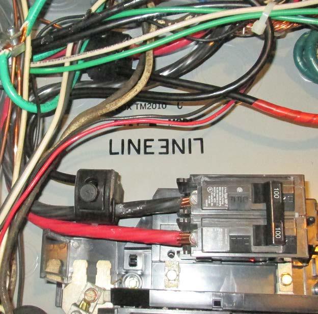
22 Examples of Tapped SE Conductors The Wrong Way Courtesy of: Mark Elsner, Town of Plymouth Conductors are terminated under lugs that are only rated for one wire, and dissimilar metals in contact with each other. 22

23 Examples of Tapped SE Conductors The Wrong Way Connection is made inside the utility meter enclosure. 23


24 PV Interconnection Considerations Terminal ratings should be followed: Conductor size Max conductors 24
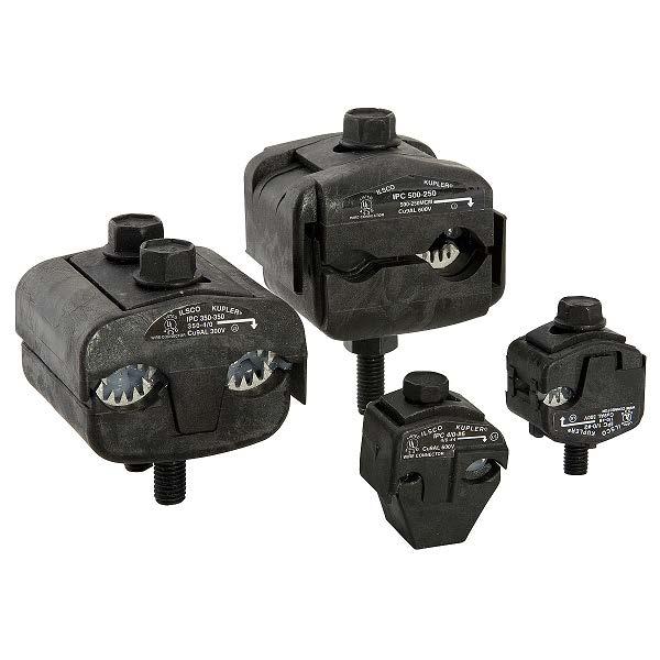

25 Insulation-Piercing Connectors/Taps Source: ILSCO.com Source: ILSCO.com 25


26 Insulation-Piercing Connectors/Taps Connectors installed outdoors must be rated for the environment. 26

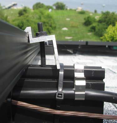
27 Custom Taps? Wire is wrapped the wrong way around the screw. 27

(2)(1) Feeders (B)(2)(3)")
28 Load Side Connection NEC Article (B) Key sections include: (B)(2)(1) Feeders (B)(2)(3) Busbar Interconnection 28
(2)(1)(a) Option (A) Feeder ampacity not less than sum of: Primary source OCPD 125% of inverter current Source:")
29 Bus or Conductor Ampere Rating - Feeders NEC Article (B)(2)(1)(a) Option (A) Feeder ampacity not less than sum of: Primary source OCPD 125% of inverter current Source: IAEI.com Existing conductors must be 29 increased in size (Option A)
(2)(1)(b) Option (B) Feeder ampacity not less than primary source OCPD Must add OCPD at interconnection")
30 Bus or Conductor Ampere Rating - Feeders NEC Article (B)(2)(1)(b) Option (B) Feeder ampacity not less than primary source OCPD Must add OCPD at interconnection Existing conductors must be protected (Option B) Source: IAEI.com 30
(2)(1) Existing conductors must be increased in size or")
31 Bus or Conductor Ampere Rating - Feeders NEC Article (B)(2)(1) Existing conductors must be increased in size or protected 31
(2)(1) Existing conductors must be increased in size or")
32 Bus or Conductor Ampere Rating - Feeders NEC Article (B)(2)(1) Existing conductors must be increased in size or protected 32
33 Bus or Conductor Ampere Rating - Busbars NEC Article (B)(2)(3)(a) Option (A) PV & Main less or equal to busbar Busbar ampacity not less than sum of: Main OCPD 125% of power source output current Main Breaker 100A Busbar 125A Example: Inverter current = 14.4A 14.4A x 125% = 18A 125% PV Output 18A 100% of 125A = 125A PV breaker can be located anywhere Main + PV = 118A 100% Busbar = 125A 118A feeds < 125A bus 33
34 Bus or Conductor Ampere Rating - Busbars NEC Article (B)(2)(3)(b) Option (B) 120% Rule 120% of busbar ampacity not less than sum of: Main OCPD 125% of power source output current Main Breaker 100A 125% PV Output 18A Busbar 100A 120% of 100A = 120A Example: Inverter current = 14.4A 14.4A x 125% = 18A Main + PV = 118A 120% Busbar = 120A 118A feeds < 120A bus PV breaker must be at opposite end Do not relocate label required 34
35 Bus or Conductor Ampere Rating - Busbars NEC Article (B)(2)(3)(c) Option (C) AC Combiner Panelboard Busbar ampacity not less than sum of: All breaker ratings (PV or other loads) Excluding main OCPD Load Breaker 20A PV Breakers 80A total Busbar 100A Permanent warning label required Example: 4 20A inverter breakers 4 x 20A = 80A Loads + PV = 100A 100% Busbar = 100A 100A loads & PV = 100A bus 35
(2)(3)(d) Option (D) 120% Rule (Center-Fed Panelboard in Dwellings) 120% of busbar ampacity not less than sum of: Main OCPD 125% of power source output current 125% PV Output 18A Example:")
36 Bus or Conductor Ampere Rating - Busbars NEC Article (B)(2)(3)(d) Option (D) 120% Rule (Center-Fed Panelboard in Dwellings) 120% of busbar ampacity not less than sum of: Main OCPD 125% of power source output current 125% PV Output 18A Example: Inverter current = 14.4A 14.4A x 125% = 18A Main Breaker 200A PV breaker can be at either end, but not both Main + PV = 218A 120% Busbar = 240A 218A feeds < 240A bus 36


37 Wire Harness and Exposed Cable AFCI Protection Former NEC Article (D)(6) Removed in 2017 NEC, no products available Intended for micro inverters Wire harness or cable output circuit rated: 240 Volts 30 Amps or less Not installed in a raceway, listed AFCI protection Circuit breaker, suitable for backfeed 37
(5) Listed plug-in type circuit breakers backfed from electric power sources that are listed and identified as interactive shall")
38 Breaker Fastening NEC Article (B)(5) Listed plug-in type circuit breakers backfed from electric power sources that are listed and identified as interactive shall be permitted to omit the additional fastener normally required by (D) for such applications. 38
39 Array Grounding/Bonding Wiring Methods Microinverters Modules 39

40 Equipment Grounding and Bonding NEC Article / A moderate amount of inspections contain issues with Array equipment grounding 40
41 Equipment Grounding and Bonding NEC Article / All metal parts likely to become energized Module frames Racking Metal raceways/enclosures Low impedance ground-fault current path back to the source or ground detector Inverter or AC panelboard 41

42 Connection of Grounding and Bonding Equipment NEC Article Listed pressure connectors Terminal bars Exothermic welding Machine screws Standard or thread-forming Engage 2 or more threads Secured with a nut Listed assembly/means Read the instructions!!! 42
43 Grounding the Racking Considerations Wire management Conductor type/material Size , PV modules, raceway/protection for smaller than #6 AWG Splices Where permissible Not in lay-in lugs 43
 and 250.")
44 Grounding the Racking Wrong Screw (110.3(B) and 250.8) 44

45 Grounding the Racking Trip Hazard 45
")
46 Module Frame Grounding NEC Article Many methods per manufacturer s instructions Lay-in lug Must be suitable for the environment in which it is installed Contact with aluminum (usually tin-plated copper) Outdoor/wet locations (suitable for direct-burial) Listed fitting WEEB Racking Integrated bonding Check the model! Plastic frame No ground required 46

47 Module Frame Grounding Unless it s plastic! 47
")
48 Module Frame Grounding Wrong Lugs (Copper or Not Listed for Outdoor) 48

49 Module Frame Grounding Right Fitting, Installed Wrong 49


50 Module Frame Grounding Integrated Bonding Considerations Some manufacturers: Only midclamps listed to bond module frames, not end clamps READ THE INSTRUCTIONS 50


51 Module Frame Grounding Integrated Bonding Considerations Other manufacturers: Midclamps and endclamps are listed to bond module frames 51
52 Conductor Protection Almost half of inspections contain issues with conductor protection Conductors shall be protected against physical damage (including those beneath array) Articles: (B)(4)(b) (A)(1) 52

53 PV conductors are not supported under the array. 53

54 PV conductors are subject to abrasion. 54

55 PV conductors are not supported and leaves and debris are collecting under the array. 55

56 Unprotected PV output conductors. 56

57 The Right Way PV output conductors installed in conduit. 57

58 The Right Way PV output conductors installed in conduit. 58

59 The Right Way PV conductors free from physical damage. 59

60 The Right Way PV conductors supported from roof surface. 60


61 PV conductors are properly supported under the array. Upper photo taken from ladder, lower photo taken from ground. 61

62 Microinverter Mounting Hardware Be aware of microinverter mounting bolt length relative to module frames!! 62
 Ground-mount arrays In readily accessible locations, conductors shall be")
63 Readily Accessible Locations NEC Article (A) Ground-mount arrays In readily accessible locations, conductors shall be guarded or installed in a raceway 63
 or be installed in a raceway.")
64 PV conductors in readily accessible locations shall be guarded (preferably not with CAUTION tape) or be installed in a raceway. 64

65 PV conductors in readily accessible locations shall be installed in a raceway. 65

66 PV conductors in readily accessible locations shall be guarded or installed in a raceway. 66

67 The Right Way Readily accessible PV conductors properly guarded. 67

68 The Right Way Readily accessible PV conductors properly guarded. 68
69 Module Mounting/Securing More than a quarter of all inspections contain issues with module/racking installation Modules shall be installed in accordance with their installation instructions, as required by NEC Article 110.3(B): Secured at proper locations Utilizing the proper hardware 69

70 Module Mounting/Securing Proper Locations Limitations for supporting modules in landscape Source: LGSolarUSA.com 70


71 Module Mounting/Securing Proper Hardware Endclamps are not one-size fits-all Midclamps typically can t be installed as endclamps 71

72 Module Mounting/Securing Rail Length Most manufacturers specify at least ½ of space: Between the end clamp and the end of the rail to Allow for thermal expansion and vibration. 72


73 Module Mounting/Securing Rail Length


74 Module Mounting/Securing Missing Hardware/Improperly Secured 74


75 Roof Penetrations/Flashing Improper/missing flashing 75


76 Lag Bolts Lag bolt missed the rafter. 76

77 Lag Bolts Lag bolts missed the rafter. 77

78 Lag Bolts 78

79 PV System Labeling 79


80 PV System Labeling Key Articles The majority of inspections contain issues labeling Many labeling requirements refer to (B) Field-Applied Hazard Markings Words, colors, symbols to meet ANSI Z NOT HAND WRITTEN Sufficient to withstand the environment involved 80


81 Labels are faded and not suitable for the environment. 81

82 Labels are faded and not suitable for the environment. 82


83 Labels are peeling and not suitable for the environment. 83


84 Labels are faded and not suitable for the environment. 84
(3) and (G)(4) On or in a building Raceways, enclosures,")
85 DC Raceway Label NEC Article (G)(3) and (G)(4) On or in a building Raceways, enclosures, every 10 Minimum 3/8 CAPS on Red 85

86 Warning labels for DC raceways shall be reflective. 86


87 PV System Disconnect NEC Article (B) 87


88 PV System Disconnect The Right Way 88
 Per 110.21(B) 89")
89 Disconnect Line/Load Energized NEC Article (B) Per (B) 89


90 2017 NEC DC Power Source NEC Article MAX SYSTEM DC-DC Converter 90

91 AC Power Source NEC Article

(3) 92")
92 Dual Power Sources NEC Article (B)(3) 92
(2)(3)(b) Per 110.")

93 Do Not Relocate NEC Article (B)(2)(3)(b) Per (B) POWER SOURCE OUTPUT CONNECTION; DO NOT RELOCATE THIS OVERCURRENT DEVICE 93

94 AC Combiner Panel NEC Article (B)(2)(3)(c) Per (B) THIS EQUIPMENT FED BY MULTIPLE SOURCES. TOTAL RATING OF ALL OVERCURRENT DEVICES, EXCLUDING MAIN SUPPLY OVERCURRENT DEVICE, SHALL NOT EXCEED AMPACITY OF BUSBAR. 94


95 Service Disconnect Directory NEC Article (B)/ Per (B) 95
96 String/Central Inverter 96
")


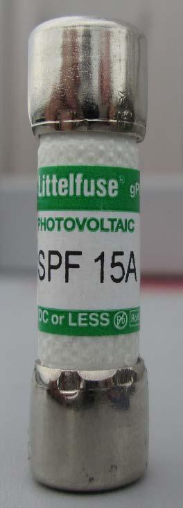

97 Fuses 690.9(D) requires listed PV overcurrent devices for DC conductors 97


98 Fuses Some inverters ship from factory without fuses. Fusing may be required depending on number of combined strings. See 690.9(A) and its exception. 98
99 Grounding Electrode System 99
100 Grounding Electrode System NEC Article (A) Buildings or Structures Supporting a PV Array Building or structure supporting a PV array shall have a grounding electrode system installed in accordance with Part III of Article 250. PV array equipment grounding conductor shall be connected to the grounding electrode system of the building or structure supporting the PV system in accordance with Part VII of Article 250. Sized in accordance with
 Close as practical to roof mounted arrays Connection per 250.52 and 250.")
101 Optional Array Grounding Electrode Conductor NEC Article (B) Ground rod intended for lightning protection Removed in 2011 NEC Back in 2014 NEC Now optional for 2017 NEC, (B) Close as practical to roof mounted arrays Connection per and Building steel may be considered a grounding electrode Permitted to connect to equipment ground Not required to connect to building grounding electrode system Direct connection to array frame or structure 101

102 Optional Array Grounding Electrode Conductor NEC Article (B) Axillary electrode required on ground mounted arrays Connection per and Pole may be considered a grounding electrode Permitted to connect to equipment ground Not required to connect to building grounding electrode system Direct connection to array frame or structure 102
103 Inverter Output and AC Circuit Disconnecting Means Wiring Methods 103
104 Disconnection of PV Equipment (Isolating Devices) NEC Article Isolating devices shall be provided to isolate PV modules, ac PC modules, fuses, dc-dc converters, inverters, and charge controllers from all conductors that are not solidly grounded 104


105 Disconnection of PV Equipment Inside the S brand Some inverters only include a DC disconnect. 105
 conductors that are not solidly")

106 Disconnection of PV Equipment (Isolating Devices) NEC Article Isolate equipment from all (power sources) conductors that are not solidly grounded Located either: Within the equipment Within sight and within 10 of equipment An additional AC disconnect may be required if the inverter does not contain one.
(5) Neutral conductor bonded to frame For bonus points: Article 200.")
107 Production Meter Violations Article (A)(5) Neutral conductor bonded to frame For bonus points: Article 200.6(A) #6 AWG & smaller reidentified Article #6 AWG & smaller reidentified 107
 Small conductors on lugs")
108 Production Meter Violations Article 110.3(B) Small conductors on lugs 108
109 Outdoor Wiring Methods 109


(4), 310.")
110 Type NM Cable NEC Article Article requires conductors to be marked. Prohibited in wet/damp locations Articles (B)(4), (C) Outdoor raceways are wet locations! Article Since 2008 NEC 110
111 Outdoor Enclosures Common violations: Not installed so as to prevent moisture from entering or accumulating in accordance with Penetrations not sealed, as required by 300.7(A) Indoor wire connectors, 110.3(B),

112 Enclosures must be installed so as to prevent moisture from entering or accumulating in accordance with

113 Enclosures must be installed so as to prevent moisture from entering or accumulating in accordance with

114 114 Enclosures must be installed so as to prevent moisture from entering or accumulating in accordance with

115 Enclosures must be installed so as to prevent moisture from entering or accumulating in accordance with
.")
116 Raceway must be sealed when passing between the interior and exterior of a building per 300.7(A). 116


117 Examples of sealant products that are listed for contact with electrical wiring. 117


118 Conductors Entering Boxes NEC Article Conductors entering boxes shall be protected The raceway or cable shall be secured to such boxes and conduit bodies 118


119 Bonding the Raceway NEC Article Conductive materials enclosing conductors SHALL BE BONDED! Plastic enclosure outside Metal inside Plastic DC disconnect 119


120 Lay-in lug Bonding Bushings Rated for Outdoor Use? Must be suitable for the environment Outdoor/wet locations (suitable for direct-burial) 120
")
121 121 A magnet may be used to determine if a lug does not contain stainless steel (outdoor) hardware.


122 Dissimilar Metals Beyond the lugs Dissimilar metals in contact will result in corrosion. 122

123 Dissimilar Metals Beyond the lugs Bare copper conductor is corroding because of contact with steel raceway. 123

124 Dissimilar Metals Beyond the lugs Bare copper conductor is corroding because of contact with steel raceway. 124

125 Rapid Shutdown of PV Systems on Buildings 125

126 Rapid Shutdown of PV Systems on Buildings NEC Article PV system circuits on or in buildings shall include a rapid shutdown function: (A) through (D) 126

127 About Article Intended to protect first responders Original 2014 proposal: Disconnect power directly under array Module-level shutdown 2014 NEC Compromise: Combiner-level shutdown 2017 NEC: Back to original, however Source: UL.com 127
128 Rapid Shutdown of PV Systems on Buildings NEC Article (A) Controlled Conductors Requirements for controlled conductors shall apply to PV circuits supplied by the PV system (B) Controlled Limits Array Boundary Defined as 1 from array in all directions 128


129 Rapid Shutdown of PV Systems on Buildings NEC Article (B)(1) Outside the 1 array boundary More than 3 inside a building 129
(1) Under 30 volts within 30 seconds Measured between: Any 2 conductors Any conductor")
130 Rapid Shutdown of PV Systems on Buildings NEC Article (B)(1) Under 30 volts within 30 seconds Measured between: Any 2 conductors Any conductor and ground Source: UL.com 130

131 Rapid Shutdown of PV Systems on Buildings NEC Article (B)(2) Effective January 1, 2019 Inside the 1 array boundary, one of following: 1. Array should be listed/field labeled as rapid shutdown 2. Controlled conductors limited to 80 volts within 30 seconds 3. Exception for arrays with no exposed wiring (solar shingles) 131
132 Rapid Shutdown of PV Systems on Buildings NEC Article (C) Initiation Device Shall be one of following: 1. Service disconnecting means 2. PV system disconnecting means 3. Readily accessible switch that plainly indicates whether it is in the off or on position Not more than 6 disconnects For one-family and two-family dwellings: Located outside! 132
 Equipment that performs the rapid shutdown shall be listed for providing rapid")
133 Rapid Shutdown of PV Systems on Buildings NEC Article (D) Equipment that performs the rapid shutdown shall be listed for providing rapid shutdown protection. 133


134 Rapid Shutdown of PV Systems on Buildings NEC Article (C)(3) Switch label that includes the following: Minimum 3/8 CAPS on Red Required even for microinverters! 134

(1)(b) Traditional shutdown outside array")
135 Rapid Shutdown of PV Systems on Buildings NEC Article (C)(1)(a) Array-level shutdown 2019 requirement (C)(1)(b) Traditional shutdown outside array boundary 2014 or 2017 requirement 135

136 Thank You Any Questions? Additional Resources: For installers: For your customer: And more at: Mass Solar Loan Team Massachusetts Clean Energy Center Tel: Fax: masscec.com Matt Piantedosi Manager of Solar Field Operations cadmusgroup.com Tel:
About Matt Piantedosi
 2017 NFPA Conference & Expo Solar PV System Inspections Best Practices and Commonly Found Violations Presented by: Matt Piantedosi Manager of Solar Field Operations The Cadmus Group About Matt Piantedosi
1. The plan needs to show compliance with the 2013 CEC, 2013 CBC and 2013 CRC. [ CBC] RESPONSE:
![1. The plan needs to show compliance with the 2013 CEC, 2013 CBC and 2013 CRC. [ CBC] RESPONSE:](/thumbs/90/102211462.jpg "1. The plan needs to show compliance with the 2013 CEC, 2013 CBC and 2013 CRC. [ CBC] RESPONSE:") Solar Panels Interactive PV system checklist: 1. The plan needs to show compliance with the 2013 CEC, 2013 CBC and 2013 CRC. [ 107.2 CBC] 2. The electrical plans show a different number of panels than
Solar Panels Interactive PV system checklist: 1. The plan needs to show compliance with the 2013 CEC, 2013 CBC and 2013 CRC. [ 107.2 CBC] 2. The electrical plans show a different number of panels than
Inspection Guide for PV Systems in One- and Two- Family Dwellings (For Rooftop Photovoltaic Systems meeting the Standard Plan)
") TOOLKIT DOCUMENT #7 Inspection Guide for PV Systems in One- and Two- Family Dwellings (For Rooftop Photovoltaic Systems meeting the Standard Plan) This document has two sections. Neither section is all-inclusive
TOOLKIT DOCUMENT #7 Inspection Guide for PV Systems in One- and Two- Family Dwellings (For Rooftop Photovoltaic Systems meeting the Standard Plan) This document has two sections. Neither section is all-inclusive
Permitting and Inspecting PV Systems. PV Codes and Standards 101. Photovoltaic System Basics
 Permitting and Inspecting PV Systems Presented by Bill Brooks, PE Brooks Engineering PV Codes and Standards 101 What are the applicable codes and standards for PV systems? Electrical codes - NEC Article
Residential Rooftop PV
 Model Inspection Checklist for PLAN REVIEW AND FIELD INSPECTION GUIDELINES Residential Rooftop PV Model Inspection Checklist for Residential Rooftop PV l PLAN REVIEW AND FIELD INSPECTION GUIDELINES l Interstate
Reference Information:
 Solar PV Simplified Standard Permit Application Requirements For: Central/String Inverter(s) & Micro-Inverter(s) Systems for One and Two Family Dwellings SCOPE: Use this application only for utility-interactive
CITY & COUNTY OF DENVER COMMUNITY PLANNING & DEVELOPMENT BUILDING PERMIT POLICY
 Page 1 of 5 REFERENCE Denver Building and Fire Code (DBC) Section 131, International Residential Code (IRC) Section M2301, the National Electrical Code (NEC) Articles 690 & 705 PROCEDURE The procedure
SECTION GROUNDING
 SECTION 16450 GROUNDING PART 1 - GENERAL 1.1 DESCRIPTION A. This section specifies general grounding and bonding requirements of electrical and telecommunication installations for personnel safety, equipment
PHOTOVOLTAIC (PV) SUBMITTAL REQUIREMENTS
 SUBMITTAL REQUIREMENTS") PHOTOVOLTAIC (PV) SUBMITTAL REQUIREMENTS Building Division 555 Santa Clara Street Vallejo CA 94590 707.648.4374 1. PERMIT INFORMATION: The installation of a photovoltaic solar electric system requires
PHOTOVOLTAIC (PV) SUBMITTAL REQUIREMENTS Building Division 555 Santa Clara Street Vallejo CA 94590 707.648.4374 1. PERMIT INFORMATION: The installation of a photovoltaic solar electric system requires
What to Look for When Conducting Plan Reviews and Inspections of Solar PV
 Presenter: Rudy Saporite Tuesday, September 12, 2017 9:45 AM - 11:15 AM WHAT TO LOOK FOR WHEN CONDUCTING PLAN REVIEWS AND INSPECTIONS OF SOLAR PV SYSTEMS SEPTEMBER 2017 ABOUT IBTS The Institute for Building
COUNTY OF RIVERSIDE BUILDING AND SAFETY DEPARTMENT PHOTOVOLTAIC PERMITTING GUIDELINES
 COUNTY OF RIVERSIDE BUILDING AND SAFETY DEPARTMENT Mike Lara Building Official PHOTOVOLTAIC PERMITTING GUIDELINES PLANS AND PERMITS In order to minimize installation problems, plans must be provided that
Code Change Alert: Permitting of Solar Photovoltaic Systems in Washington State
 Code Change Alert: Permitting of Solar Photovoltaic Systems in Washington State Emergency Rule Regarding Rooftop Solar Photovoltaic Installations On June 13, 2014 the Washington State Building Code Council
Address of Installation Building Permit #
 TOWN OF NISKAYUNA NY State Unified Solar Permit Application One Niskayuna Circle, Niskayuna NY 12309 Phone: 518-386-4522 Fax: 518-386-4592 Email: buiding@niskayuna.org The Town of Niskayuna has adopted
NY State Unified Solar Permit
 PERMIT APPLICATION NY State Unified Solar Permit Unified solar permitting is available statewide for eligible solar photovoltaic (PV) installations. Municipal authorities that adopt the unified permit
Small Scale Solar Permit Application
 Town of Berne Small Scale Solar Permit Application Town of Berne PO Box 57 Berne, NY 12023 (518) 872-1448 2/14/18 PROJECT ELIGIBILITY FOR PERMITTING PROCESS By submitting this application, the applicant
Building and Safety Division Public Information
 B&S STD E-18 Solar Photovoltaic (PV) Systems Revised: January, 2017 The following document outlines the requirements for the issuance of building and electrical permits for solar photovoltaic systems.
NY State Unified Solar Permit
 PERMIT APPLICATION NY State Unified Solar Permit Unified solar permitting is available statewide for eligible solar photovoltaic (PV) installations. Municipal authorities that adopt the unified permit
Field Inspection Guideline for PV Systems
 Field Inspection Guideline for PV Systems Prepared for: Interstate Renewable Energy Council (available at www.irecusa.org) Brooks Engineering 873 Kells Circle Vacaville, CA 95688 www.brooksolar.com Prepared
UNIVERSITY SERVICES ANNEX James Madison University Harrisonburg, Virginia State Project Code: Architect s Project Number:
 SECTION 260526 - GROUNDING AND BONDING FOR ELECTRICAL SYSTEMS PART 1 - GENERAL 1.1 RELATED DOCUMENTS A. Drawings and general provisions of the Contract apply to this Section. 1.2 SUMMARY A. This Section
NY State Unified Solar Permit
 PERMIT APPLICATION NY State Unified Solar Permit Unified solar permitting is available statewide for eligible solar photovoltaic (PV) installations. Municipal authorities that adopt the unified permit
NORTHEASTERN REMC ELECTRIC STANDARDS MANUAL
 NORTHEASTERN REMC ELECTRIC STANDARDS MANUAL WARNING Before digging or trenching... Call 811 Indiana Underground Protection Service 1-800-382-5544 AVOID BURIED POWER CABLES 4901 East Park 30 Drive P.O.
NY State Unified Solar Permit
 PERMIT APPLICATION- City of Elmira NY State Unified Solar Permit Unified solar permitting is available statewide for eligible solar photovoltaic (PV) installations. Municipal authorities that adopt the
PV System Permitting and Inspection. PV Codes and Standards Uniform Solar Energy Code
 PV System Permitting and Inspection Presented by Bill Brooks, PE Brooks Engineering PV Codes and Standards 101 What are the applicable codes and standards for PV systems? Electrical codes - NEC Article
SECTION GROUNDING AND BONDING FOR ELECTRONIC SAFETY AND SECURITY
 PART 1 - GENERAL 1.1 DESCRIPTION SECTION 28 05 26 GROUNDING AND BONDING FOR ELECTRONIC SAFETY AND SECURITY SPEC WRITER NOTE: Delete // // if not applicable to project. Also delete any other item or paragraph
WITH THE TITLE 24. replacement. story. stories, etc. R disconnects. to, PV. unit and any. supporting frame. conditions. greater than the main
 CITY OF CYPRESS Building Division 5275 Orange Avenue, Cypress, California 906300 714-229-6730 buildingpermits@ @ci.cypress.ca.us RESIDENTIAL PHOTOVOLTAIC SYSEMS ALL WORK SHALL REQUIRE COMPLIANCE WITH THE
NY State Unified Solar Permit
 PERMIT APPLICATION NY State Unified Solar Permit Unified solar permitting is available statewide for eligible solar photovoltaic (PV) installations. Municipal authorities that adopt the unified permit
NY State Unified Solar Permit
 VILLAGE OF UPPER BROOKVILLE PERMIT APPLICATION NY State Unified Solar Permit Unified solar permitting is available statewide for eligible solar photovoltaic (PV) installations. Municipal authorities that
NY State Unified Solar Permit
 VILLAGE OF FARMINGDALE NY State Unified Solar Permit Unified solar permitting is available statewide for eligible solar photovoltaic (PV) installations. Municipal authorities that adopt the unified permit
NY State Unified Solar Permit
 PERMIT APPLICATION NY State Unified Solar Permit Unified solar permitting is available statewide for eligible solar photovoltaic (PV) installations. Municipal authorities that adopt the unified permit
NY State Unified Solar Permit
 PERMIT APPLICATION NY State Unified Solar Permit PROJECT ELIGIBILITY FOR UNIFIED PERMITTING PROCESS By submitting this application, the applicant attests that the proposed project meets the established
Bulletin Grounding and bonding of solar photovoltaic systems Rules , , , and
 Bulletin 64-2-0 Grounding and bonding of solar photovoltaic systems Rules 64-064, 64-066, 64-068, 64-070 and 64-222 Scope (1) Introduction (2) Grounding of solar photovoltaic system output, ac grounding
SECTION SECONDARY UNIT SUBSTATIONS
 SECTION 26 12 16 SECONDARY UNIT SUBSTATIONS PART 1 GENERAL 1.1 SUMMARY This section describes metal-clad, indoor or outdoor, secondary unit substations with integral primary fused disconnect switches,
SERVICES CHAPTER 35. wire. For all other installations, the rating of the ungrounded conductors shall be not less than 60 amperes.
 CHAPTER 35 SERVICES SECTION E3501 GENERAL SERVICES E3501.1 Scope. This chapter covers service conductors and equipment for the control and protection of services and their installation requirements. E3501.2
Photovoltaic System Inspector Job Task Analysis Guide April 2017
 Photovoltaic System Inspector Job Task Analysis Guide April 2017 V. 04.17 www.nabcep.org Raising Standards. Promoting Confidence. NABCEP mission is to establish and operate high quality Credentialing programs
SECTION BUSWAYS
 PART 1 - GENERAL 1.1 DESCRIPTION SECTION 26 25 11 BUSWAYS SPEC WRITER NOTE: Delete between //----// if not applicable to project. Also delete any other item or paragraph not applicable to the section and
NY State Unified Solar Permit
 PERMIT APPLICATION NY State Unified Solar Permit Unified solar permitting is available statewide for eligible solar photovoltaic (PV) installations. Municipal authorities that adopt the unified permit
OVERHEAD SERVICES - SECONDARY
 OVERHEAD SERVICES - SECONDARY Contents - Overhead Services... O-1 General Requirements for Overhead Service... O-2 Names of Parts for Overhead Service... O-3 Service Attachment on an Unguyed Service Mast...
Building Codes in Effect: 2010 California Building, Residential, Fire, Energy and Electrical Codes, including Article 690.
 AGUA CALIENTE BAND OF CAHUILLA INDIANS A SOVEREIGN TRIBAL GOVERNMENT Planning & Development Department Building and Safety Division 5401 Dinah Shore Drive Palm Springs, CA 92264 (760) 669-6800 RESIDENTIAL
(Condensed from National Electric Code)
") WIRING, SPECIFICATIONS, INSPECTION, AND METER INSTALLATION PROCEDURES FOR RESIDENTIAL CUSTOMERS SERVED BY SOUTHWEST ARKANSAS ELECTRIC COOPERATIVE CORPORATION Effective April 1, 1974 Revised February 3,
WIRING, SPECIFICATIONS, INSPECTION, AND METER INSTALLATION PROCEDURES FOR RESIDENTIAL CUSTOMERS SERVED BY SOUTHWEST ARKANSAS ELECTRIC COOPERATIVE CORPORATION Effective April 1, 1974 Revised February 3,
NORTHEASTERN REMC ELECTRIC STANDARDS MANUAL
 NORTHEASTERN REMC ELECTRIC STANDARDS MANUAL WARNING Before digging or trenching... Call Indiana Underground Protection Service 1-800-382-5544 AVOID BURIED POWER CABLES CONTENTS Page # 100-200 OR 400 AMP
A. Provide a complete Distribution Panelboard system as indicated on the drawings, and as specified herein.
 16470 PANELBOARDS ************************************************************************************************************* SPECIFIER: CSI MasterFormat 2004 number: 26 24 16 An optional keynote to
SERVICE ENTRANCES. OPPD S Electrical Service Designer (ESD) shall designate the Point Of Entrance.
 shall designate the Point Of Entrance.") SERVICE ENTRANCES 3.01 POINT OF ENTRANCE General Service The customer, or the customer s electrician, should provide OPPD with a site plan, load schedule, and voltage requirements when requesting service.
SERVICE ENTRANCES 3.01 POINT OF ENTRANCE General Service The customer, or the customer s electrician, should provide OPPD with a site plan, load schedule, and voltage requirements when requesting service.
PV Codes and Standards 101
 BUILDING & INSPECTING CODE-COMPLIANT PV SYSTEMS Presented by Bill Brooks, PE Brooks Engineering Overview of Presentation PV System Basics Introduction to relevant Codes and Standards Summary of PV Electrical
PV SYSTEMS AND WORKMANSHIP
 Perspectives on PV pv systems and workmanship A series of articles on photovoltaic (PV) power systems and the National Electrical Code PV SYSTEMS AND WORKMANSHIP by John Wiles With electrical systems lifetimes
2008 NEC Guide Lines for Home Owner Doing Electrical Work on their Property
 2008 NEC Guide Lines for Home Owner Doing Electrical Work on their Property A brief summary of the most used code references for residential wiring State of Idaho Division of Building Safety Electrical
SECTION GROUNDING AND BONDING
 SECTION 16060 PART 1 GENERAL 1.01 DESCRIPTION A. Section includes requirements for an electrical grounding system, including electrodes, grounding rods, connectors, insulators, equipment grounding and
Revisions for the 2011 National Electrical Code - Part 2
 PDHonline Course E356 (3 PDH) Revisions for the 2011 National Electrical Code - Part 2 Instructor: Patrick Ouillette 2012 PDH Online PDH Center 5272 Meadow Estates Drive Fairfax, VA 22030-6658 Phone &
EFFECTIVE DATE: November 1, 2011, unless a later date is cited at the end of a section. [ NMAC - Rp,
 TITLE 14 CHAPTER 10 PART 4 HOUSING AND CONSTRUCTION ELECTRICAL CODES 2011 NEW MEXICO ELECTRICAL CODE 14.10.4.1 ISSUING AGENCY: The Construction Industries Division of the Regulation and Licensing Department.
National Electrical Code and Safety Considerations when Grounding Photovoltaic Modules via Rack Mounting Hardware
 National Electrical Code and Safety Considerations when Grounding Photovoltaic Modules via Rack Mounting Hardware There are a number of issues which should be considered when evaluating the grounding system
NEC 2017 Code Changes Chapter 1 - General
 NEC 2017 Code Changes Chapter 1 - General Changes from the 2014 code are highlighted in yellow. ARTICLE 110 - Requirements for Electrical Installations Part I. General 110.1 Scope. This article covers
Solar Photovoltaic (PV) Systems Questions and Answers Revised July 1, 2017
 Systems Questions and Answers Revised July 1, 2017") Solar Photovoltaic (PV) Systems Questions and Answers Revised July 1, 2017 (This document is subject to change as solar PV technologies and codes continue to evolve) The following frequently asked questions
Solar Photovoltaic (PV) Systems Questions and Answers Revised July 1, 2017 (This document is subject to change as solar PV technologies and codes continue to evolve) The following frequently asked questions
METERING INSTALLATION
 4.01 METERING SPECIFICATIONS METERING INSTALLATION Metering specifications will be issued to the customer by OPPD. Metering specifications are required before any work is started on all new wiring or additions
Temporary Wiring Practices And Guidelines For NECA. National Electrical Contractors Association Omaha, Nebraska
 Temporary Wiring Practices And Guidelines For NECA National Electrical Contractors Association Omaha, Nebraska Table of Contents I. Planning II. Lighting and Power III. Maintenance IV. Inspections V. Routing
Standard of Practice - Campus Electrical Distribution System
 A26.3 Standard of Practice - Campus Electrical Distribution System NOTE: Significant revisions or additions to the previous standards are highlighted in italics. GENERAL Designers shall verify that all
Manitoba Electrical Code
 THE MANITOBA HYDRO ACT (C.C.S.M. c. H190) Manitoba Electrical Code Regulation 76/2018 Registered June 15, 2018 Adoption of Canadian Electrical Code, Part I, 24th edition 1 Subject to section 3 and the
NORTHWESTERN UNIVERSITY PROJECT NAME JOB # ISSUED: 03/29/2017
 SECTION 26 0526 - GROUNDING AND BONDING FOR ELECTRICAL SYSTEMS PART 1 - GENERAL 1.1 RELATED DOCUMENTS A. Drawings and general provisions of the Contract, including General and Supplementary Conditions
2017 NEC Changes for Renewable Energy Systems Session one by Christopher LaForge
 2017 NEC Changes for Renewable Energy Systems Session one 2017 by Christopher LaForge Christopher LaForge IREC Certified Master Trainer NABCEP Certified Photovoltaic Installation Professional 30 years
SECTION GROUNDING AND BONDING
 SECTION 16060 GROUNDING AND BONDING PART 1 - GENERAL 1.1 RELATED DOCUMENTS A. Drawings and general provisions of the Contract, including General and Supplementary Conditions and Division 1 Specification
Revisions for the 2014 National Electrical Code Part 2
 PDH Course E429 Revisions for the 2014 National Electrical Code Part 2 Patrick S. Ouillette, P.E. 2014 PDH Online PDH Center 5272 Meadow Estates Drive Fairfax, VA 22030-6658 Phone & Fax: 703-988-0088 www.pdhonline.org
BULLETIN SUBJECT: GENERAL BULLETIN, 2015 SASK INTERPRETATIONS CORRECTIONS, AND ELECTRIC SERVICE REQUIREMENT CHANGES OR ADDITIONS
 SaskPower Electrical Inspections BULLETIN 01-2017 February 15, 2017 TO: LICENSED ELECTRICAL CONTRACTORS ELECTRICAL CONSULTANTS AND ENGINEERS SUBJECT: GENERAL BULLETIN, 2015 SASK INTERPRETATIONS CORRECTIONS,
Basic Requirements for Residential Electrical Installations
 Basic Requirements for Residential Electrical Installations Wayne County Building Department 428 West Liberty Street Wooster, Ohio 44691 Phone: 330-287-5525 Fax: 330-287-5649 This brochure is intended
ELECTRIC METERING GENERAL
 1.0 INDEX 1.0 INDEX 2.0 SCOPE 3.0 GENERAL REQUIREMENTS 4.0 EQUIPMENT 5.0 METER REQUIREMENTS 6.0 METER FACILITIES 7.0 ELECTRICAL CONNECTIONS 2.0 SCOPE This guide covers general requirements and codes for
SECTION PART 1 GENERAL
 SECTION 16060 GROUNDING AND BONDING PART 1 GENERAL 1.1 SUMMARY A. Section Includes: Grounding of electrical systems and equipment and basic requirements for ground for equipment, circuits, and systems.
Proposals and Process 2017 National Electrical Code
 Proposals and Process 2017 National Electrical Code for Solar America Board for Codes and Standards Stakeholder Meeting; October 23, 2014 Ward Bower Ward Bower Innovations LLC Introduction The New NFPA
2003 International Residential Code ELECTRICAL PROVISIONS ONLY October 2005 EDITORIAL CHANGES SEVENTH PRINTING
 2003 International Residential Code ELECTRICAL PROVISIONS ONLY October 2005 EDITORIAL CHANGES SEVENTH PRINTING E3305.3: now reads The space equal to the width and depth of the panelboard and extending
Click here to get back to 2011 NEC Code Updates Part 1
 www.garyklinka.com Page 1 of 13 2011 NEC Code Updates Code Language Part 1 Click here to get back to 2011 NEC Code Updates Part 1 100 Definitions Ampacity. The maximum current, in amperes, that a conductor
FOR ALL STAKEHOLDERS TO HAVE A SUCCESSFUL PROJECT
 Our Goal is FOR ALL STAKEHOLDERS TO HAVE A SUCCESSFUL PROJECT with us and that together we keep people and structures safe and buildings economically viable to serve the needs of our community. We strive
CONTENTS. B. System Design and Performance Requirements
 16060 Grounding and Bonding This document provides design standards only, and is not intended for use, in whole or in part, as a specification. Do not copy this information verbatim in specifications or
A. All materials shall be tested and listed by an OSHA approved Nationally Recognized Testing Laboratory (NRTL).
.") 16450 GROUNDING ************************************************************************************************************* SPECIFIER: CSI MasterFormat 2004 number: 26 05 26 An optional keynote to the
16450 GROUNDING ************************************************************************************************************* SPECIFIER: CSI MasterFormat 2004 number: 26 05 26 An optional keynote to the
MREC March, 2005 Powering the Dairy Industry
 Mark A. Cook Manager Licensed Designer of Engineering Systems Certified Commercial and UDC Electrical Inspector Certified Master Electrician Public Service Commission of Wisconsin mark.cook@starband.net
MECKLENBURG COUNTY. Land Use and Environmental Service Agency Code Enforcement 7/14/10 ELECTRICAL CONSISTENCY MEETING. Code Consistency Questions
 MECKLENBURG COUNTY Land Use and Environmental Service Agency Code Enforcement 7/14/10 ELECTRICAL CONSISTENCY MEETING Code Consistency Questions 1. We were turned down for an underground installation of
POOLS, SPAS AND HOT TUBS
 POOLS, SPAS AND HOT TUBS City of San Juan Capistrano Development Services Department 32400 Paseo Adelanto San Juan Capistrano, CA 92675 Phone: (949) 493-1171 Fax: (949) 661-5451 http://www.sanjuancapistrano.org/
DOWNTOWN UNDERGROUND NETWORK SECONDARY SERVICES GUIDELINES
 Guidelines effective March 5, 2007 NES is committed to providing safe, reliable electric service at a reasonable price for all of our customers. These guidelines offer direction for activities relating
Please check with your local inspection authority for any additional requirements before installation.
 Specifications for Residential Underground Electric Service Installation This brochure addresses most typical residential underground service installations. Variances for the following specifications must
6. SECONDARY SERVICES (under 600 volts) 6.1 AVAILABILITY For the electrical characteristics of available secondary services see Section 3.4.
 6.1 AVAILABILITY For the electrical characteristics of available secondary services see Section 3.4.") 6. SECONDARY SERVICES (under 600 volts) 6.1 AVAILABILITY For the electrical characteristics of available secondary services see Section 3.4. 6.2 OVERHEAD SERVICES Wiring of any premises for connection
6. SECONDARY SERVICES (under 600 volts) 6.1 AVAILABILITY For the electrical characteristics of available secondary services see Section 3.4. 6.2 OVERHEAD SERVICES Wiring of any premises for connection
Solar PV Standard Plan Simplified Microinverter and ACM Systems for One- and Two-Family Dwellings
 1 P a g e ATTACHMENT 6 Solar Standard Plan Simplified Microinverter and ACM Systems for One- and Two-Family Dwellings AC inverter output rating of 10 kw, with a maximum of 3 branch circuits, one module
37-SDMS-01 REV. 03 SPECIFICATIONS FOR
 37-SDMS-01 REV. 03 SPECIFICATIONS FOR LOW VOLTAGE MOLDED CASE CIRCUIT BREAKERS FOR SERVICE CONNECTIONS This specification is property of SEC and subject to change or modification without any notice CLAUSE
6. SECONDARY SERVICES (under 600 volts) 6.1 AVAILABILITY For the electrical characteristics of available secondary services see Section 3.4.
 6.1 AVAILABILITY For the electrical characteristics of available secondary services see Section 3.4.") 6. SECONDARY SERVICES (under 600 volts) 6.1 AVAILABILITY For the electrical characteristics of available secondary services see Section 3.4. 6.2 OVERHEAD SERVICES Wiring of any premises for connection
6. SECONDARY SERVICES (under 600 volts) 6.1 AVAILABILITY For the electrical characteristics of available secondary services see Section 3.4. 6.2 OVERHEAD SERVICES Wiring of any premises for connection
Specifications for Residential Overhead Electric Service Installation
 Specifications for Residential Overhead Electric Service Installation This brochure addresses most typical residential overhead service installations. Variances for the following specifications must be
2015 Code Rollout Meeting Q & A
 1 SECTION QUESTION SaskPower Inspections Dept. ANSWER 2 3 4 5 6 7 8 9 10 11 12 15-02-024 15-02-200 15-02-200 15-02-200 15-02-314 Are existing single or double 'weather proof when not in use' covers allowed
Top Changes 2014 NEC
 Top Changes 2014 NEC MICHAEL JOHNSTON EXECUTIVE DIRECTOR STANDARDS AND SAFETY NECA General Information This presentation previews significant changes for the 2014 NEC. Two-part series on 2014 NEC changes
EFFECTIVE DATE: July 1, 2008, unless a later date is cited at the end of a section. [ NMAC - Rp,
 TITLE 14 CHAPTER 10 PART 4 HOUSING AND CONSTRUCTION ELECTRICAL CODES 2008 NEW MEXICO ELECTRICAL CODE 14.10.4.1 ISSUING AGENCY: The Construction Industries Division of the Regulation and Licensing Department.
Title: YALE OFFICE OF FACILITIES PROCEDURE MANUAL Chapter: 01 - Yale Design Standard Division: Electrical Standards
 Date Description of Change Pages / Sections Modified ID 6/15/16 Updated format, division title, and removed references to other sections. - mgl44 A. Summary This section contains design criteria for the
TEMPORARY METER POLE INSTALLATION
 TEMPARY METER POLE INSTALLATION MEMBER PROVIDED Location to be made by REMC within 50' of our transformer or existing service Temporary pole to be properly braced 24" 3 wire weatherhead (located 24" from
A. Section includes busway and fittings including plug-in units.
 SECTION 26 25 00 ENCLOSED BUS ASSEMBLIES PART 1 - GENERAL 1.1 SUMMARY A. Section includes busway and fittings including plug-in units. 1.2 REFERENCES A. Institute of Electrical and Electronics Engineers:
SPECIAL SPECIFICATION 6499 Environmentally controlled Communications Building
 2004 Specifications CSJ 0720-03-095 SPECIAL SPECIFICATION 6499 Environmentally controlled Communications Building 1. Description. Furnish and install Environmentally Controlled Communications Building
OVERHEAD SERVICES - RESIDENTIAL & GENERAL SERVICE. See Chapter 3, Section 3.01 for more information about point of entrance (POE).
.") 6.01 GENERAL OVERHEAD SERVICES - RESIDENTIAL & GENERAL SERVICE See Chapter 3, Section 3.01 for more information about point of entrance (POE). In all cases, the customer installs, owns, and maintains the
6.01 GENERAL OVERHEAD SERVICES - RESIDENTIAL & GENERAL SERVICE See Chapter 3, Section 3.01 for more information about point of entrance (POE). In all cases, the customer installs, owns, and maintains the
The Canadian Electrical Code (Saskatchewan Amendments) Regulations, 1999
 Regulations, 1999") CANADIAN ELECTRICAL CODE 1 The Canadian Electrical Code (Saskatchewan Amendments) Regulations, 1999 Repealed by Chapter E-6.3 Reg 8 (effective June 24, 2003). Formerly Chapter E-6.3 Reg 6 (effective March
CANADIAN ELECTRICAL CODE 1 The Canadian Electrical Code (Saskatchewan Amendments) Regulations, 1999 Repealed by Chapter E-6.3 Reg 8 (effective June 24, 2003). Formerly Chapter E-6.3 Reg 6 (effective March
MUSCO ENGINEERING ASSOCIATES Consulting Engineers
 Consulting Engineers website: www.muscoengineering.com 375 Morgan Lane, Unit 307 West Haven, CT 06516 Telephone #: (203) 932-1901 Fax #: (203) 931-1550 email: admin@muscoengineering.com Electrical Equipment
TABLE OF CONTENTS CHAPTER 2 WIRING AND PROTECTION CHAPTER 1 GENERAL RULES... 19
 TABLE OF CONTENTS About This Textbook... xvii How to Use the National Electrical Code... 1 Article 90 Introduction to the National Electrical Code... 7 90.1 Purpose of the NEC... 7 90.2 Scope of the NEC...
ELECTRICAL BULLETIN
 PO Box 697 Halifax, Nova Scotia B3J 2T8 Labour and Advanced Education ELECTRICAL BULLETIN 2012-01 From: David MacLeod,C.E.I.,P.Eng. Pg 1 of 8 Provincial Chief Electrical Inspector Date : March 1, 2012
a) Line and load compartments must be separated by a stable barrier.
 Line and load compartments must be separated by a stable barrier.") 1.00 GENERAL 1.01 The electric utility shall furnish and connect all meters, instrument transformers, test switches, and meter control wiring necessary to complete the meter installation. 1.02 The customer
1.00 GENERAL 1.01 The electric utility shall furnish and connect all meters, instrument transformers, test switches, and meter control wiring necessary to complete the meter installation. 1.02 The customer
SECTION FACILITY LIGHTNING PROTECTION
 PART 1 - GENERAL 1.1 DESCRIPTION SECTION 26 41 00 FACILITY LIGHTNING PROTECTION SPEC WRITER NOTE: Delete between //----//if not applicable to project. Also delete any other item or paragraph not applicable
Essex County College - West Essex Campus Addition And Renovations dlb # / 11-14
 SECTION 270526 - GROUNDING AND BONDING FOR COMMUNICATIONS PART 1 - GENERAL 1.1 RELATED DOCUMENTS A. Drawings and general provisions of the Contract, including General and Supplementary Conditions and Division
UNITED COOPERATIVE SERVICES. SPECIFICATIONS FOR SELF-CONTAINED METER INSTALLATIONS August 2014
 UNITED COOPERATIVE SERVICES SPECIFICATIONS FOR SELF-CONTAINED METER INSTALLATIONS August 2014 A member may obtain a new, single phase service from the Cooperative by providing or purchasing a meter loop.
2. Article (A) Delete the measurement of 6 feet 7 inches and insert: 66 inches (5 feet 6 inches).
 Delete the measurement of 6 feet 7 inches and insert: 66 inches (5 feet 6 inches).") H. The National Electric Code 2011 is hereby revised: 1. Article 230.70 (A) (1) Delete in its entirety and insert: 230.70 (A) (1) Readily Accessible Location. The service disconnect means shall be installed
H. The National Electric Code 2011 is hereby revised: 1. Article 230.70 (A) (1) Delete in its entirety and insert: 230.70 (A) (1) Readily Accessible Location. The service disconnect means shall be installed
SECTION GROUNDING AND BONDING FOR ELECTRICAL SYSTEMS
 SECTION 26 05 26 - GROUNDING AND BONDING FOR ELECTRICAL SYSTEMS PART 1 - GENERAL 1.1 RELATED DOCUMENTS A. Drawings and general provisions of the Contract, including General and Supplementary Conditions
WIRING METHODS CHAPTER 38
 CHAPTER 38 WIRING METHODS SECTION E3801 GENERAL REQUIREMENTS E3801.1 Scope. This chapter covers the wiring methods for services, feeders and branch circuits for electrical power and distribution. E3801.2
METERING INSTALLATIONS (GENERAL REQUIREMENTS)
") 1. METER SOCKETS Meter sockets are supplied and installed by the customer or an electrical contractor. The meter socket shall be mounted so the socket jaws are in true horizontal and vertical planes and
1. METER SOCKETS Meter sockets are supplied and installed by the customer or an electrical contractor. The meter socket shall be mounted so the socket jaws are in true horizontal and vertical planes and
Site Survey in Project Info Structural Info Electrical Info
 PROJECT INFORMATION Project Name: Site Survey in 1 2 3 Project Info Structural Info Electrical Info ***ASTERISK COLOR CODE KEY*** = Required Field = Account Preference HOMEOWNER INFORMATION First Name: