Phase II Report on Hydrology, Hydraulics, and Low Water Dams
|
|
|
- Benedict Rodgers
- 6 years ago
- Views:
Transcription


1 Phase II Report on Hydrology, Hydraulics, and Low Water Dams Arkansas River Corridor Tulsa, OK May 2005 Submitted To: U. S. Army Corps of Engineers Tulsa District Prepared by: The GUERNSEY Team 5555 N. Grand Blvd. Oklahoma City, OK
2 Table of Contents Section Page 1.0 Background/Requirements...1 Figure 1: Site Location Map General Summary of Hydrology and Hydraulics Dam Locations Low Water Dam No. 1 (City of Broken Arrow) Low Water Dam No. 2 (City of Bixby) Low Water Dam No. 3 (City of Jenks/Yale Avenue Bridge) Low Water Dam No. 4 (City of Tulsa/96 th Street and Creek Turnpike Bridges) Low Water Dam No. 5 (City of Tulsa) Low Water Dam No. 6 (City of Tulsa) Low Water Dam No. 7 (Sand Springs) Low Water Dam No. 8 (Sand Springs) Hydraulic Backwater Evaluations General Concept Plan Low Water Dam No. 2 (City of Bixby) Low Water Dam No. 3 (City of Jenks/Yale Avenue Bridge) Low Water Dam No. 4 (City of Tulsa/96 th Street and Creek Turnpike Bridges) Low Water Dam No. 5 (City of Tulsa) Low Water Dam No. 6 (City of Tulsa) Low Water Dam No. 7 (Sand Springs) HEC RAS Computer Printouts Backwater Model Summary Tables...14 Figure 2 Typical Cross Section of Low Water Dam...15 Figure 3 Arkansas River Profile with Low Water Dams Figure 4 Pedestrian/Maintenance Bridge over Low Water Dams Estimates of Probable Development Costs Initial Capital Costs of Low Water Dams Maintenance of Low Water Dams...18 Figures 5, 6, and 7 Cost Summary Sheets Other Considerations for River Development PSO Rock Dam Potential Island...21 TOC - 1
3 6.3 Other Types of Low Water Dams Hydropower Evaluation Environmental Issues Water Quality Evaluations INCOG Water Quality Report Recommendations Recommendations for Next Phase Study...24 TOC - 2
4 1.0 BACKGROUND/REQUIREMENTS Aerial photographs provided by the Indian Nation Council Of Governments (INCOG) and the Phase I Vision Plan prepared by Carter & Burgess were reviewed for the purpose of evaluating the various locations for future low water dams on the Arkansas River between Keystone Dam and the Tulsa/Wagoner County line southeast of Broken Arrow, Oklahoma. This information was used in conjunction with data obtained through Project team meetings, agency consultation, technical evaluations, and preliminary environmental information collected for the Phase II Master Plan and Pre-Reconnaissance Study. GUERNSEY Team member HISINC, L.L.C. performed the hydrologic and hydraulic analyses for the Phase II study. Figure 1 provides a Site Location Map for the Arkansas River Corridor. This figure depicts the proposed low water dam locations from the Phase I Vision Plan and identifies the technically feasible dam locations identified in this Hydrology and Hydraulics Analysis Report (H/H Report). The purpose the H/H Report is to: convey the results of the detailed engineering evaluations of each of the low water dams identified in Phase I discuss the development sequencing of the low water dams that were evaluated, classify the low water dams based on their technical and economic feasibility, and identify those low water dams that are recommended for further detailed analysis and consideration in the continuing phases of Vision Page 1 of 24
5 FIGURE 1 SITE LOCATION MAP Page 2 of 24


6 SAND SPRINGS TULSA JENKS Technically Feasible Low Water Dam Location BROKEN ARROW BIXBY SITE LOCATION MAP ARKANSAS RIVER MASTER PLAN AND PRE-RECONNAISSANCE STUDY C.H. G UERNSEY FIGURE 1 EDAW ALABACK DESIG N HISINC MAY 2005
7 2.0 GENERAL SUMMARY OF HYDROLOGY AND HYDRAULICS The U.S. Army Corps of Engineers, Tulsa District (Tulsa District) completed the updating of the Hydrologic Engineering Centers, River Analysis System (HEC RAS) hydraulic backwater elevations and floodplain limits model for the Arkansas River in late December 2004 and the Corps Super hydrology/flows model in early January This data will be used in the new Arkansas River backwater model that will be the basis for a Letter of Map Revision (LOMR) to the Federal Emergency Management Agency (FEMA) on behalf of Tulsa County sometime in The previous backwater model was developed in 1977 as part of the initial FEMA Flood Insurance Study (FIS) and had not been thoroughly reviewed since that time. The new backwater model is based on new cross sections derived from 2002 aerial topography, on-site field survey cross sections, and Arkansas River sedimentation range data. The cross section locations in the new model are different than the original model; however, the bridge locations and river mile designations are very similar. Similarly, the Tulsa District has updated the existing Super hydrology model and re-evaluated the hydraulic spillway capacity of Keystone Dam. A detailed review of the new model has not been performed as part of this study. However, based on discussions with the Tulsa District s modelers there is very little change in the water surface elevations from the 1977 model, and floodplain limits are being revised primarily based on the new more detailed topographic mapping. The Tulsa District indicates that the new hydrology shows the originally accepted 170,000 cubic feet per second (cfs) for the Base Flood flow, commonly accepted to be the 100-Year event, will be raised to 205,000 cfs. However, the Arkansas River has been degraded and eroded over the past 25 years leading to increased channel storage. The increased channel storage allows the River to handle a larger flow without a noticeable increase in water surface elevation. A copy of the April 2001 Flood Emergency Plan for Keystone Lake was provided by the Tulsa District for this H/H Report. This document addresses the flooding limits on the Arkansas River for the maximum spillway discharge, 940,000 cfs, and the flooding limits in the event of a dam breach. The previously identified maximum historical inflow to Keystone Lake was 344,000 cfs during the October 1986 flood. The maximum recorded flow at the United States Geological Survey (USGS) Tulsa gage was 301,800 cfs from this same flooding event. Floodplain mapping for the new Arkansas River backwater model is currently in process at the Tulsa District. As stated, this new mapping will be submitted to FEMA for modification of the existing FEMA Flood Insurance Rate Maps (FIRM) which will be issued after the new hydrology study, new backwater modeling, and proposed changes to the FEMA FIRM floodplain limits have been accepted by FEMA. This will establish the new floodplain Page 3 of 24
8 boundaries for the Arkansas River between Keystone Dam and the Tulsa/Wagoner County Line. When complete, these boundaries will provide the basis for preparing maps to illustrate the elevations of the Base Flood flow or 100-year event, as well as flood elevations for the maximum release rate from Keystone Dam that can be maintained by the current levee system along the Arkansas River Corridor. Page 4 of 24
9 3.0 LOW WATER DAM LOCATIONS The following is a summary of the proposed locations presented in the Phase I Vision Plan, and the potential relocation of some existing low water dams including the rationale behind the proposed relocations. The potential locations are presented beginning at the Tulsa/Wagoner County line and proceeding upstream to Keystone Dam. 3.1 LOW WATER DAM NO. 1, CITY OF BROKEN ARROW The proposed location of this low water dam is between the extension of 145th East Avenue and 161st East Avenue, located downstream of a future nature park and upstream of the existing City of Broken Arrow wastewater treatment plant. There are currently no bridges crossing the Arkansas River at these locations, but there is a long range plan for a bridge extending East 161st Street South to connect with South 193 rd East Avenue downstream of this low water dam location. The Phase I Vision Plan proposes the expansion of recreational sports complexes in the Indian Springs area. The low potential for commercial, residential, and recreational development in this area suggests that a low water dam would be a long range consideration. 3.2 LOW WATER DAM NO. 2, CITY OF BIXBY This proposed low water dam location is downstream of Memorial Road Bridge. The existing bridge provides easy access for construction of the dam, while the river lake created by the dam would enhance visual aesthetics from the Bridge. The Memorial Road Bridge would also provide ready access to development around the low water dam location. There are two existing sand and gravel operations at the bridge location that could be incorporated into the operation and maintenance of the new river lake. The City of Bixby has no current economic development plans adjacent to the Arkansas River, though there are several private subdivisions being developed on both the north and south side of the Arkansas River at the current time, along with some small private commercial developments. This location has high volume traffic loads and the existing City Park on the north side of the Arkansas River has been recently renovated with the addition of an amphitheatre. The reasonable potential for commercial, residential, and recreational development in this area makes a low water dam feasible within a 5 to 15-year timeframe. Page 5 of 24
10 3.3 LOW WATER DAM NO. 3, JENKS/SOUTH TULSA YALE AVENUE BRIDGE This proposed low water dam location is southeast of the future privately-funded Yale Avenue Bridge southeast of the City of Jenks. Once constructed, this bridge would provide access for construction of the dam, while the river lake created by the dam would enhance the view from the Bridge. The Bridge would also provide ready access to development around the low water dam and associated river lake. The Public Service Company of Oklahoma (PSO) Riverside Station, an electrical generating station, is upstream of this location and the impoundment would provide a more constant water supply for PSO s station. There is also an existing sand and gravel operation opposite the PSO Riverside Station that could be incorporated into the operation and maintenance of the new river lake. There is a future park and residential development proposed south of East 121st Street South. The proposed Yale Avenue Bridge will be a privately owned toll bridge and financing for this project is currently in progress. There is good potential for commercial, residential, and recreational development due to the planned construction of the Yale Avenue Bridge at this location. 3.4 LOW WATER DAM NO. 4, JENKS/SOUTH TULSA 96 TH STREET AND CREEK TURNPIKE BRIDGES This proposed low water dam location is downstream of the 96 th Street and Creek Turnpike Bridges and upstream of the Polecat Creek Confluence. The existing bridges would provide visual and vehicular access to the low water dam and river lake area from both the eastbound and west-bound traffic. A low water dam and river lake would enhance the new Oklahoma Aquarium, the Riverwalk Crossing Area, and the proposed Creek Nation Development with an attractive water feature. There is an existing sand and gravel operation downstream of this location on the west bank of the River that could be incorporated into the operation and maintenance of the new river lake. There is extensive commercial, recreational, and residential development in this area and a low water dam would likely result in short range economic benefits. 3.5 LOW WATER DAM NO. 5, CITY OF TULSA UPSTREAM OF 81 ST STREET This site is shown on the Phase I Vision Plan to be located upstream of 81st Street and upstream of the confluence with Joe Creek. There is a potential for short range economic benefits of a low water dam in this location; however, the City of Tulsa Southside Wastewater Treatment Plant on the downstream side of Interstate 44 (I-44) would discharge its wastewater treatment plant effluent directly into the river lake created by Low Water Dam No. 5. Page 6 of 24
11 3.6 LOW WATER DAM NO. 6, CITY OF TULSA UPSTREAM OF I-44 This dam, as shown on the Phase I Vision Plan, is to be located upstream of the I-44 Bridge. There are currently plans and right-of-way acquisitions for widening Skelly Drive which will change in the River corridor characteristics. The location of the Southside Wastewater Treatment Plant likely makes relocating this low water dam from its Phase I Vision Plan location infeasible. The treatment plant effluent needs to discharge downstream of a low water dam to minimize the water quality impacts to the pool. A low water dam at this location has the potential to impact the existing kayaking activities at the existing PSO rock dam by raising the tailwater level of the existing riffle and reducing the whitewater effect. The height of the new dam may need to be lower in this location to avoid these impacts. The potential for commercial, residential, and recreational development exists at this location. The River Parks Low Water Dam and Zink Lake at 21 st Street are next in sequence traveling upstream from Low Water Dam No LOW WATER DAM NO. 7, SAND SPRINGS MAIN STREET The site for this low water dam in the Phase I Vision Plan is downstream of the Highway 97 Bridge near the Main Street extension. The existing bridge would allow ready access to the dam. The dam and the river lake could be seen both from the existing bridge and the existing park. The dam would also impound water at the Sand Springs River City Park which is proposed to be enhanced, along with the area to the north of River City Park into the Main Street area of Sand Springs. Also there is an existing Sand Springs Gravel/Mohawk Materials Sand and Gravel operation on the upstream side of the Highway 97 Bridge that could benefit commercially from sand and gravel maintenance operations for the proposed low water dam, since the available volume of sand and gravel is diminishing in this reach of the Arkansas River. This area of the Arkansas River is being strategically addressed for commercial and recreational development and the presence of a low water dam downstream of the Highway 97 Bridge supports this strategy. 3.8 LOW WATER DAM NO. 8, SAND SPRINGS 177 TH WEST AVENUE This low water dam as shown on the Phase I Vision Plan would be located downstream of a future 177 th West Avenue bridge as well as the existing bald eagle habitat area and extension of the River City Park. This area currently exhibits a low potential for commercial, residential, and recreational development in the short- and mid-range timeframe; thus a low water dam in this area is likely a long range consideration. Page 7 of 24
12 4.0 HYDRAULIC BACKWATER EVALUATIONS The following is a summary of the hydraulic backwater evaluations performed during the H/H Report for the low water dams proposed for future study under the Vision 2025 planning. The low water dams have been categorized, based upon technical and economic feasibility, as: Tier 1 short range development, less than 5 years, Tier 2 mid-range development, 5-15 years, Tier 3 long range development, greater than 15 years, or Infeasible based on technical, economic, or environmental impacts. In addition, other comments on potential enhancements along the reach of the River will be noted. Low water dams number 1 and number 8 have been categorized as Tier 3 and were not analyzed further in this H/H Report. Copies of the HEC RAS backwater model output data for both the U.S. Army Corps of Engineers base model dated December 2004 and the proposed Project model prepared as a part of this H/H Report are included in Section 4.8. In addition, a backwater summary table has been developed to compare the water surface elevations, energy grade elevations, channel velocities, flow area, and top width for the 100-Year, 1986 historic flood event, and the levee design flows provided by the Corps of Engineers. A copy of the HEC RAS models on CD is being provided to the U.S. Army Corps of Engineers for their use in review of the proposed modeling that has been performed as part of this Phase II evaluation. In each case, the proposed Project model elevations are equal to, or less than the existing Corps of Engineers base model elevations, thus surmising the hydraulic design of the proposed low water dams are acceptable and meet all of the hydraulic criteria presented earlier in the H/H Report. 4.1 GENERAL CONCEPT PLAN The general concept plan for each low water dam is to provide multiple sets of bascule gates across the entire crest of each low water dam. With this concept, the possibility of storing significant sediments, sands, and gravels on the upstream side of the each low water dam is reduced. Each gate or set of gates would require a hydraulic operator at each end of each gate. These hydraulic operators would be housed in towers adjacent to each gate or fixed ogee weirs along the crest of the dam. The towers would also provide structural support for the pedestrian/maintenance walkway proposed for construction above each of the low water dams. The pedestrian/maintenance walkways would also connect the east and west Page 8 of 24
13 banks of the Arkansas River for easy access to recreational, commercial, and residential locations. The main structure of each low water dam will be a reinforced concrete ogee spillway section with a fixed crest elevation. This structure provides the support for the gates and provides uncontrolled spillway capacity to pass Arkansas River flows. It is proposed to create a hydraulically efficient pier nose and tail at each tower location. As with the original Zink Lake Dam, the operational concept is proposed to maintain a fixed pool level between 0 cfs flow and approximately 10,000 cfs flow. A hydraulic operator will cause the gates to open or close based on signals from an upstream level controller. Above some yet to be determined flow rate, the bascule gates are fully opened on the bottom of the Arkansas River, allowing Arkansas River flows to pass both through the entire gate opening and over the fixed ogee weir. The bascule gates will begin to close once the flows decrease to some yet to be determined rate. The hydraulic operators on the bascule gates are set to a fully open fail safe operation in the event of loss of hydraulic pressure or mechanical failure to assure that each low water dam would not cause an upstream flooding impact in the event of a mechanical failure. Each gate should be operated periodically to assure that it is functional. Each low water dam is required to be hydraulically designed to pass the Base Flood flow, currently understood to be the 100-Year flood event, without causing a rise in the upstream water surface elevation, in accordance with FEMA, the City of Tulsa, the U.S. Army Corps of Engineers, and Tulsa County floodplain management criteria. Each low water dam that was hydraulically evaluated in this study meets these criteria within current standards of hydraulic design. The elevations and assumed dam heights to achieve these results are subject to change when further detailed studie s are performed. For each low water dam location, it will be necessary to consider more detailed field survey data, geologic stratum, land ownership, and economic development opportunities on the banks of the Arkansas River. For each low water dam a hydraulic concept design was created and input into the HEC RAS backwater analysis. At the end of this section is a Summary Table that presents the new Corps of Engineers Backwater model results and compares them with those generated having the low water dams included in the model. 4.2 LOW WATER DAM NO. 2, CITY OF BIXBY Low Water Dam No. 2 is proposed to be located downstream of Memorial Road Bridge at River Station in the new Corps of Engineers HEC RAS backwater model. Page 9 of 24
14 This low water dam is proposed to have three sets of bascule gates across the crest of the dam. These could either be sets of four 45-foot long gates, or sets of two 100-foot long gates. For the hydraulic modeling in this study, sets of four 45-foot long gates were considered since there will be more towers required thus creating more obstruction in the Arkansas River floodplain. The proposed bottom of each gate is at Elev based on the best available data from the INCOG aerial topography and the new Corps of Engineers HEC RAS backwater model. The fixed ogee crest is proposed to be at Elev thus creating a 7-foot deep pool at the upstream face of the low water dam. This is the maximum height of dam that can be created at this location, based on the information available, without causing a rise in the water surface elevation. The recreational river lake that is created will reach to approximately River Sta or 2.2 river miles upstream to approximately 5,000 feet downstream of Low Water Dam No. 3. This location would be feasible from an engineering and economic perspective; however, negative water quality effects would be associated with this dam. Water quality issues are further discussed in Section 7.0 of this report. Based on the negative water quality impacts associated with Low Water Dam No. 2, it has been categorized as infeasible at this time. 4.3 LOW WATER DAM NO. 3, JENKS/SOUTH TULSA YALE AVENUE BRIDGE Low Water Dam No. 3 is proposed to be located downstream of the proposed privatelyfunded Yale Avenue Bridge southeast of the City of Jenks at River Station in the new Corps of Engineers HEC RAS backwater model. This low water dam is proposed to have five sets of bascule gates across the crest of the dam. These could either be sets of four 45-foot long gates, or sets of two 100-foot long gates. For the hydraulic modeling in this study, sets of four 45-foot long gates were considered since there will be more towers required thus creating more obstruction in the Arkansas River floodplain. The proposed bottom of each gate is at Elev based on the best available data from the INCOG aerial topography and the new Corps of Engineers HEC RAS backwater model. The fixed ogee crest is proposed to be at Elev thus creating a 6.5-foot deep pool at the upstream face of the low water dam. This is the maximum height of dam that can be created at this location, based on the information available, without causing a rise in the water surface elevation. This low water dam has more gates due to the width of the Arkansas River at this location. The final location would be dependent on the location and modification of the Arkansas River banks after the proposed Yale Avenue Bridge is located and constructed. The recreational river lake would reach to approximately River Sta or 3 river miles upstream to the downstream side of Low Water Dam No. 4. This location would be feasible from an engineering and economic perspective; Page 10 of 24
15 however, negative water quality effects would be associated with this dam. Water quality issues are further discussed in Section 7.0 of this report. Based on the negative water quality impacts associated with Low Water Dam No. 3, it has been categorized as infeasible at this time. 4.4 LOW WATER DAM NO. 4, JENKS/SOUTH TULSA 96 TH STREET AND CREEK TURNPIKE BRIDGES Low Water Dam No. 4 is proposed to be located downstream of the 96 th Street and Creek Turnpike Bridges and upstream of the Polecat Creek Confluence at River Station in the new Corps of Engineers HEC RAS backwater model. This low water dam is proposed to have three sets of bascule gates across the crest of the dam. These could either be sets of four 45-foot long gates, or sets of two 100-foot long gates. For the hydraulic modeling in this study, sets of four 45-foot long gates were considered since there will be more towers required thus creating more obstruction in the Arkansas River floodplain. The proposed bottom of each gate is at Elev based on the best available data from the INCOG aerial topography and the new Corps of Engineers HEC RAS backwater model. The fixed ogee crest is proposed to be at Elev thus creating an 8-foot deep pool at the upstream face of the low water dam. This is the maximum height of dam that can be created at this location, based on the information available, without causing a rise in the water surface elevation. The recreational river lake that is created will reach to approximately River Sta or 2.9 river miles upstream to approximately 3,100 feet downstream of the 71 st Street Bridge over the Arkansas River and downstream of the effluent discharge location from the City of Tulsa Southside Wastewater Treatment Plant. This low water dam location is classified as a Tier 1 dam location based on technical feasibility and potential economic benefits. This low water dam site is proposed as one of the conceptual plan locations for low water dams in the Phase II Master Plan. 4.5 LOW WATER DAM NO. 5, CITY OF TULSA UPSTREAM OF 81 ST STREET Low Water Dam No. 5 is proposed to be located upstream of the Joe Creek Confluence near 81 st Street at River Station in the new Corps of Engineers HEC RAS backwater model. This low water dam was modeled with three sets of bascule gates across the crest of the dam. The hydraulic modeling included both sets of four 45-foot long gates, and sets of two 100-foot long gates. The proposed bottom of each gate was at Elev based on the Page 11 of 24
16 best available data from the INCOG aerial topography and the new Corps of Engineers HEC RAS backwater model. The fixed ogee crest was initially set at Elev thus creating a 6.5-foot deep pool at the upstream face of the low water dam. Multiple trials of dam configurations were evaluated with none meeting the no-rise criteria established for installation of a low water dam. Each trial run reduced the dam height by 0.5 feet until the final runs were set with a dam height of 3.0 feet which is considered non-economic. The downstream Low Water Dam No. 4 creates a river lake that causes a backwater effect through most of the proposed pool that would be created by Low Water Dam No. 5 and tails out downstream of the 71 st Street Bridge. Based on the hydraulic modeling and negative water quality effects, detailed in Section 7.0, Low Water Dam No. 3 is categorized infeasible. 4.6 LOW WATER DAM NO. 6, CITY OF TULSA UPSTREAM OF I-44 Low Water Dam No. 6 is proposed to be located upstream of the I-44 Bridge and upstream of the Cherry Creek confluence at River Station in the new Corps of Engineers HEC RAS backwater model. This low water dam is proposed to have three sets of bascule gates across the crest of the dam. These could either be sets of four 45-foot long gates, or sets of two 100-foot long gates. For the hydraulic modeling in this study, sets of four 45-foot long gates were considered since there will be more towers required thus creating more obstruction in the Arkansas River floodplain. The proposed bottom of each gate is at Elev based on the best available data from the INCOG aerial topography and the new Corps of Engineers HEC RAS backwater model. The fixed ogee crest is proposed to be at Elev thus creating an 8-foot deep pool at the upstream face of the low water dam. This is the maximum height of dam that can be created at this location, based on the information available, without causing a rise in the water surface elevation. The recreational river lake that is created will reach to approximately River Sta or 1.9 river miles upstream to a point between the existing PSO rock dam and the downstream side of the existing Zink Lake Low Water Dam. A dam at this location and at this height will affect the existing kayaking activity on the west bank of the Arkansas River by increasing the tailwater elevation of the white water area and reducing the hydraulic head that creates the white water effect. A shorter dam could be used at this location to avoid impacts to the kayaking area; however, a smaller river lake would result from this change. Based the proposed level and timeframe of development, Low Water Dam No. 6 is categorized as Tier 2, for mid-range, 5 to 15 year, consideration. Page 12 of 24
17 4.7 LOW WATER DAM NO. 7, SAND SPRINGS MAIN STREET Low Water Dam No. 7 is proposed to be located downstream of the Highway 97 Bridge near the Main Street extension at River Station in the new Corps of Engineers HEC RAS backwater model. This low water dam is proposed to have three sets of bascule gates across the crest of the dam. These could either be sets of four 45-foot long gates, or sets of two 100-foot long gates. For the hydraulic modeling in this study, sets of four 45-foot long gates were considered since there will be more towers required thus creating more obstruction in the Arkansas River floodplain. The proposed bottom of each gate is at Elev based on the best available data from the INCOG aerial topography and the new Corps of Engineers HEC RAS backwater model. The fixed ogee crest is proposed to be at Elev thus creating a 7-foot deep pool at the upstream face of the low water dam. This is the maximum height of dam that can be created at this location, based on the information available, without causing a rise in the water surface elevation. The recreational river lake that is created will reach to approximately River Sta or 4.8 river miles upstream to a point near the Shell Creek confluence with the Arkansas River. This low water dam location is classified as a Tier 1 dam location based on technical feasibility and potential economic benefits. This low water dam site is proposed as one of the conceptual plan locations for low water dams in the Phase II Master Plan. 4.8 HEC RAS BACKWATER COMPUTER RUN SUMMARIES This section presents the summary printouts from the HEC RAS Backwater Modeling. There are two sets of HEC RAS computer printout summaries for each modeling plan. Plan 01 is the Tulsa District s Base Model that was provided to the Project Team in December 2004 which represents the newly created Arkansas River model that will be used for the FEMA Letter of Map Revision of the currently effective Flood Insurance Rate Maps for Tulsa County. One set of summary printouts presents only the 100-Year, 1986 Flood event and the Levee Design Flows. The second set of summary printouts presents the 10- Year, 50-Year, 100-Year, 500-Year 1986 Flood event, Water Quality Flows provided to INCOG, and the Levee Design Flows. Plan 02 is the Tulsa District s Base Model that has been modified to add cross sections and low water dams at each of the locations described in the preceding sections. One set of summary printouts presents only the 100-Year, 1986 Flood event and the Levee Design Flows. The second set of summary printouts presents the 10-Year, 50-Year, 100-Year, Page 13 of 24
18 500-Year 1986 Flood event, Water Quality Flows provided to INCOG, and the Levee Design Flows. A Summary Table has also been created for the each of the following flood events: Base/100-Year Flood, 1986 Flood Event, and the Levee Design Flow. Data from each of the HEC RAS Plans 01 and 02 were input into these Summary Tables to provide a ready comparison of the change in water surface elevation, energy grade elevation, channel velocity, flow area, and top width of the floodwaters between the Base Corps Model and the Proposed Low Water Dam Model. Figure 2 shows a typical low water dam representative of those being recommended for further detailed analysis. Figure 3 shows the Arkansas River profile including the proposed low water dams and associated river lakes. Page 14 of 24
19 FIGURE 2 - TYPICAL CROSS SECTION OF A LOW WATER DAM Page 15 of 24

20
21 FIGURE 3 ARKANSAS RIVER PROFILE Page 16 of 24
22
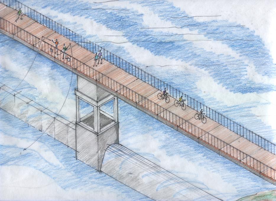
23 FIGURE 4 PROPOSED CONCEPT FOR PEDISTRIAN/MAINTENANCE BRIDGE OVER THE TOP OF THE LOW WATER DAM. Page 17 of 24
24
25 5.0 ESTIMATES OF PROBABLE DEVELOPMENT COSTS 5.1 INITIAL CAPITAL COSTS OF LOW WATER DAMS An estimate of the initial capital costs of a typical low water dam with three sets of bascule gates was created for this report. To develop these costs not only were the initial construction costs considered, but also the design engineering, construction management, and legal and administrative costs. The costs for the pedestrian/maintenance bridge were developed by the Project Team and are included as a separate category from the low water dam costs. Financing costs are not included at this time. Specific quotations were obtained from a manufacturer of the bascule gates that are proposed to be utilized for the typical low water dam. A preliminary design of the reinforced concrete fixed ogee section of the dam was prepared to estimate the concrete quantities and rock excavation quantities. An allocation, based on the original design of the Zink Lake Low Water Dam was made for the electrical and mechanical portions of the typical low water dam, considering that there will be additional sets of gates across the entire crest of the low water dam. The cost summary sheets for the typical low water dam are included at the end of this section as Figures 5, and 6. Figure 7 shows the cost estimate for rehabilitation of Zink Dam. Detailed cost sheets are available upon written request. 5.2 MAINTENANCE OF LOW WATER DAMS One of the major criticisms of the existing low water dam that creates Zink Lake is the issue of sedimentation. During the original design, extensive investigations were made concerning options for maintaining Zink Lake. Due to lack of initial capital funding, the number of bascule gates were reduced from the original design which reduced the capability to pass suspended sand during high flow events. Again, due to reduced maintenance funding capability, an undersized dredge was purchased by the River Parks Authority which was not able to perform adequately and was eventually eliminated from use. It is recommended that as a part of the development of any additional low water dams an initial escrow account be established that will provide perpetual financial resources for proper maintenance of the existing and any new river lakes that are created. Adequate equipment, permitting, manpower, etc. needs to be established to maintain the new river lakes. In addition, for some of the low water dams in locations where there are existing sand and gravel operations, a concept has been considered for collection and transfer of sand and Page 18 of 24
26 gravel to the banks of the Arkansas River that will minimize maintenance dredging operations for the dam operators, and with the support of the sand and gravel operators, could reduce the collection costs of the existing sand and gravel operations. A meeting was held with the sand and gravel operation owners on the Arkansas River during this Phase II study. Based on extensive discussions of various maintenance concepts, and the currently diminishing volume of sand and gravel that is being transported downstream by the higher frequency flooding events, it was generally concluded that any type of mechanical or hydraulic sand collection system built into the new low water dams would not be economical. Instead, the sand and gravel operators would consider periodically dredging the pools upstream of each low water dam on an approximate five year cycle. The sand and gravel operators requested the opportunity to review the quality of the sand and gravel in Zink Lake and evaluate the approximate quantities. With this information, and if a staging area is made available by the River Parks Authority for storage handling and truck loading in the immediate area, the sand and gravel operators would consider removing the sand and gravel buildup at little or no cost to River Parks Authority or other governing agency, and would sell the sand and gravel to cover their costs of performing the maintenance dredging. Another issue raised by the staff of the River Parks Authority is the accessibility for maintenance of the gates and hydraulic equipment. It is proposed in the future low water dams to create a pedestrian walkway/maintenance access bridge over the operating towers in each of the gate bays along the low water dam. A preliminary concept is shown on Figure 4. These towers would provide the structural support for the pedestrian walkway/maintenance access bridge and would allow maintenance vehicles to drive onto the bridge to perform periodic maintenance of the hydraulic equipment used to operate the gates. An alternate to the periodic sand and gravel removal is the additional of another set of gates in the center of the existing Zink Lake Dam. This option is similar to the original design concept prepared in This would require dewatering of the existing Zink Lake for approximately 3 months, the removal of a section of the existing low water dam, construction of two towers to support the new hydraulic gate operators, installation of the new gate sections, and construction of an electrical and hydraulic duct bank in the rock ledge either upstream or downstream of the existing dam sill to connect to the existing hydraulic system. Upgrading of the control system would also be required to interconnect the new gate sections. Discussions were raised about the use of an upstream siltation basin as a possible solution to the existing sedimentation issue. The main problem with this concept is the approach velocities from the existing rock sill upstream of the I-244 Bridge to the downstream side of the new 11 th Street Bridge. There is an eroded section near all of the bridge piers that is Page 19 of 24
27 over 12 feet deep due to the high velocities, therefore an upstream sedimentation basin is not applicable in this reach of the Arkansas River. Page 20 of 24
28 FIGURES 5, 6, and 7 - COST SUMMARY SHEET Page 21 of 24
29
30
31
32 6.1 PSO ROCK DAM 6.0 OTHER CONSIDERATIONS FOR RIVER DEVELOPMENT The old rock dam just south of the existing low water dam could be rebuilt or cleaned up as the diversion for the water intake on the west bank of the River. It would not be feasible to create a new concrete low water dam there, and it would detract from the existing historical significance of the existing rock diversion dam. However, both sides of the River in this area need to be improved and the rock dam maintained for aesthetics. This is also an area that is currently used for kayaking, and this reach of the River could possibly be extended to further fulfill this purpose. 6.2 POTENTIAL ISLAND At 161 st West Avenue, approximately 13 miles upstream of the Highway 97 Bridge Crossing, there is an area in the existing riverbed that has a large sand bar. This can be seen from Highway 412 heading west and from Highway 51 heading east. This would be a good location for a new natural habitat island with trees, etc. like the Smith Islands at the River Parks Zink Lake. It would have to be evaluated in the backwater model, but there is no other development in the area and an island could provide a wildlife sanctuary area. 6.3 OTHER TYPES OF LOW WATER DAMS One issue that has been raised during various discussions is alternative types of low water dams such as inflatable dams. There are many benefits with the inflatable type dam; however, there is always one major impediment vandalism. Though the major manufacturers of the rubber bladders that create the inflatable dam have examined many different types of fabrics, there has been no solution to penetration by rifle bullets, knives, or arrows from high power bows. Municipalities, rural water districts, etc. that currently have these types of dams, whether in an urban area or in a remote rural area, generally concur that the maintenance costs associated with the vandalism and the interruption of operation of the dams are major issues. Several owners have removed the inflatable dams and replaced them with alternate steel type gates to avoid loss of water. Other weir types may be feasible upon further analysis. 6.4 HYDROPOWER EVALUATION The Tulsa District requested the consideration of hydropower at each of the proposed low water dams. Hydropower provides a renewable/green energy source utilizing the natural river flows in the Arkansas River combined with the hydraulic power head developed with the creation of the low water dams. In the early 1980 s, a report was prepared for the U.S. Page 22 of 24
33 Department of Energy to evaluate high flow, low head turbine-generator technology for applications such as the Arkansas River. At that time, every known manufacturer of turbines or generators was contacted to evaluate the available technology. Though there were types of equipment commercially available, the economic evaluation of such applications was not feasible from an initial capital investment or a maintenance and operation perspective. During this study, the remaining viable turbine manufacturers in the world were contacted to determine the status of this older technology. Each manufacturer responded that the high flow, low head technology did not develop after the initial concept in the early to mid 1980 s and that such projects were determined at that time, and still today, not to be economically feasible. 6.5 AQUATIC LIFE ISSUES There has been discussion concerning the potential for fish passage around/over the proposed low water dams. Other issues have been raised regarding the preservation of existing fisheries in the River. Information concerning the migration and spawning periods of the various species of fish will be developed and this information will be compared with the historical flows in the Arkansas River. The initial evaluations determined that the migrations generally occur during historic higher flow periods when there is sufficient depth of water over the low water dams and the tailwater elevations are higher, thus there is no significant differential between the upstream pool elevation and the downstream tailwater elevation. Thus, during periods of high flows, there is sufficient depth of water flow over each of the low water dams to allow fish passage without restriction. During periods of low flows, there may not be sufficient water depths to pass fish and therefore mitigation measures may be required in the design of future low water dams, and possible remediation of the existing low water dam at Zink Lake. 6.6 WATER QUALITY EVALUATONS INCOG performed an update of the water quality model for the Arkansas River as part of the Vision 2025 planning process. The Guernsey Team supported this modeling effort by coordinating the new Corps of Engineers hydraulic backwater model with the INCOG water quality model to develop compatible cross section locations between the two models. Then INCOG used the preliminary conceptual design data for the proposed low water dams to evaluate the water quality impact at the various dam locations evaluated to determine any change in water quality in the pool areas as a result of the possible installation of the low water dams. A copy of the INCOG Water Quality Evaluation report is presented herewith. Page 23 of 24
34 7.0 INCOG WATER QUALITY REPORT The INCOG Water Quality Report presented in this section was prepared as a part of the evaluation of the Arkansas River to determine the impact on the dissolved oxygen with the addition of certain low water dams. The two Tier 1 low water dams Dam No. 4 south of 96 th Street Bridge in Jenks/South Tulsa area and Dam No. 7 east of Highway 91 in Sand Springs did not exhibited unacceptable dissolved oxygen levels. Dam No. 6, upstream of I-44, is classified as a Tier 2 dam and does not present unacceptable dissolved oxygen levels. The Tier 3 dams, Dam No. 1 and Dam No. 8, were not included in this analysis. Low Water Dam Nos. 2 and 3 were demonstrated to create unacceptable dissolved oxygen levels and are, therefore, considered infeasible at this time. Page 24 of 24
35
36
37
38
39 8.0 RECOMMENDATIONS 8.1 RECOMMENDATIONS FOR NEXT PHASE STUDY Based on the hydraulic evaluations performed to date, the following recommendations are made for the next phase of study: 1. Specific site locations be established in the field for the two proposed low water dams classified as Tier Field surveys be performed in the reach of each location to provide detailed topographic information concerning the locations, including sufficient area upstream and downstream of the proposed axis of the low water dam to adjust the location as necessary. 3. Preliminary geotechnical explorations be made with the general area of the proposed low water dams to establish the foundation conditions for each Tier 1 low water dam. 4. Detailed conceptual plans be developed for each Tier 1 low water dam. With this data, the hydraulic backwater analyses should be updated to finalize the maximum height of each dam. 5. The cost estimate be updated using the detailed conceptual plans. 6. The feasibility of each Tier 1 low water dam be determined, considering all factors of commercial and economic development, maintenance, etc. Page 25 of 24
Conceptual-Level Cost Estimates Arkansas River Corridor Dam Improvement and River Bank Stabilization Projects
 TECHNICAL MEMORANDUM Conceptual-Level Cost Estimates Arkansas River Corridor Dam Improvement and River Bank Stabilization Projects TO: COPIES: PREPARED BY: Tulsa County File CH2M HILL DATE: September 2,
Conceptual Design and Feasibility of a Natural Fishway at the Fremont BART Weir, Alameda Creek, California
 Conceptual Design and Feasibility of a Natural Fishway at the Fremont BART Weir, Alameda Creek, California Final Report September 2005 Prepared by Center for Ecosystem Management and Restoration, Oakland,
Freight Street Development Strategy
 Freight Street Development Strategy Appendix B: Naugatuck River Floodplain Analysis Freight Street Development Strategy DECEMBER 2017 Page B-1 1.0 NAUGATUCK RIVER FLOODPLAIN AT FREIGHT STREET 1.1 Watershed
Appendix P. U.S. Fish and Wildlife Service Planning Aid Letter
 Appendix P U.S. Fish and Wildlife Service Planning Aid Letter This page is intentionally left blank. United States Department of the Interior FISH AND WILDLIFE SERVICE Missouri Ecological Services Field
APPENDIX A HYDROLOGIC AND HYDRAULIC ANALYSIS
 APPENDIX A HYDROLOGIC AND HYDRAULIC ANALYSIS GENERAL The Hydrologic and Hydraulic information presented in this appendix is provided as a supplement to the Dallas Floodway Extension General Re-evaluation
THE EFFECTS OF URBANIZATION ON THE MINGO CREEK WATERSHED
 THE EFFECTS OF URBANIZATION ON THE MINGO CREEK WATERSHED by Tim Marshall (presented at the Sixth Conference on Hydrometeorology in Indianapolis, IN, 1984) 1. INTRODUCTION Urbanization of flood plains presents
Appendix Q Draft Location Hydraulic Study Report For the State Route 32 Widening Between Fir Street and Yosemite Drive at Dead Horse Slough and South
 Appendix Q Draft Location Hydraulic Study Report For the State Route 32 Widening Between Fir Street and Yosemite Drive at Dead Horse Slough and South Fork Dead Horse Slough in the, California Draft Location
ATTN: Regulatory Office 1645 South 101 st East A venue Tulsa, OK
 Public Notice U.S. Army Corps of Engineers Tulsa District Reply To: U.S. Army Corps of Engineers ATTN: Regulatory Office 1645 South 101 st East A venue Tulsa, OK 74128-4609 SWT-2013-179 Public Notice No.
Red River Flooding. June 2015 Caddo and Bossier Parishes. Presented by: Richard Brontoli RRVA, Executive Director
 Red River Flooding June 2015 Caddo and Bossier Parishes Presented by: Richard Brontoli RRVA, Executive Director Kiwanis Club of SE Shreveport May 2, 2018 Where the Rain Falls Matters I-30 versus I-20 Caddo
Hackensack River Flood Reduction Study Update
 Township of River Vale Hackensack River Flood Reduction Study Update November 11, 2013 Purpose of Study To Analyze Where Frequent Flooding Is Impacting Property and How It Might Be Reduced Hackensack River
Missouri River Bed Degradation Integrated Feasibility Study and Environmental Impact Statement
 Pubic Scoping Meeting Missouri River Bed Degradation Integrated Feasibility Study and Environmental Impact Statement Jesse Granet Environmental Resources Specialist Kansas City, MO March 11, 2014 US Army
4. Present Activities and Roles
 4. Present Activities and Roles The present missions, authorities, activities and roles of the various agencies involved with flood protection, floodplain management and flood-damage reduction are identified
IAFSM 2010 Annual Conference. City of Rockford Keith Creek Greenway Flood Mitigation Project
 IAFSM 2010 Annual Conference City of Rockford Keith Creek Greenway Flood Mitigation Project March 10, 2010 Introduction Problem Overview 1890 s Building of homes along Keith Creek 1920 s Home construction
VII - WATER CONTROL PLAN
 VII - WATER CONTROL PLAN 7-01. General Objectives. Regulation of Saylorville Lake in conjunction with Lake Red Rock provides flood control benefits along both the Des Moines and Mississippi Rivers. Additionally,
SECTION 7.0 PROJECT FEASIBILITY, ENGINEER S RECOMMENDATION AND DESIGN ISSUES NEEDING RESOLUTION
 SECTION 7.0 PROJECT FEASIBILITY, ENGINEER S RECOMMENDATION AND DESIGN ISSUES NEEDING RESOLUTION 7.1 PROJECT FEASIBILITY The determination of project feasibility is based upon several criteria established
Engineering Report Preliminary Floodplain Study. Executive Summary
 Executive Summary Engineering Report Preliminary Floodplain Study The Federal Emergency Management Agency (FEMA) has updated the Flood Insurance Rate Maps (FIRM) for Finney County, including the City of
Ceresco Dam Removal Project. Michigan Watershed Summit March 25, 2015 Luke Trumble, P.E., MDEQ-WRD Jay Wesley, MDNR-Fisheries
 Ceresco Dam Removal Project Michigan Watershed Summit March 25, 2015 Luke Trumble, P.E., MDEQ-WRD Jay Wesley, MDNR-Fisheries Outline Overview of Ceresco Dam History Public Process Funding Dam Removal Ecosystem
MILL CREEK FISH PASSAGE CONCEPTUAL DESIGNS FINAL REPORT
 MILL CREEK FISH PASSAGE CONCEPTUAL DESIGNS FINAL REPORT Prepared for Tri State Steelheaders Contact: Brian Burns 216 N. Roosevelt, PO Box 1375 Walla Walla, WA 99362 Prepared by Waterfall Engineering, L.L.C.
Dallas Floodway Improvements
 TRINITY RIVER CORRIDOR PROJECT Dallas Floodway Improvements Refinement of the Balanced Vision Plan - Update to the Trinity River Committee 01-March March-2004 Status of the Urban Design Study As result
S.R. 4007, Section 14B PADEP Environmental Assessment Form. Enclosure C Description of Aquatic Habitat
 S.R. 4007, Section 14B PADEP Environmental Assessment Form Description of Aquatic Habitat Cresheim Creek is the only water resource that exists within the project area. No jurisdictional wetlands were
Presentation Overview
 Little Dry Creek Restoration Deep River Flood Risk Management Final Presentation to LCRBDC June 10, 2015 Presentation Overview Project Overview & Background Information Data Collection Model Development
Project Information. Pursuant to Section 404 of the Clean Water Act (33 U.S. Code 1344), notice is hereby given that
, notice is hereby given that") US ARMY Corps Of Engineers Little Rock District JOINT PUBLIC NOTICE CORPS OF ENGINEERS STATE OF ARKANSAS Application Number: 2014-00083-1 Date: December 22, 2014 Comments Due: January 16, 2015 TO WHOM
US ARMY Corps Of Engineers Little Rock District JOINT PUBLIC NOTICE CORPS OF ENGINEERS STATE OF ARKANSAS Application Number: 2014-00083-1 Date: December 22, 2014 Comments Due: January 16, 2015 TO WHOM
Prepared for: City of Jeffersonville. November Prepared by
 JEFFERSONVILLE STORMWATER MASTER PLAN HYDRAULICS APPENDIX JEFFERSONVILLE, INDIANA Prepared for: City of Jeffersonville November 2011 Prepared by Christopher B. Burke Engineering, Ltd. 115 W. Washington
Case Studies in Hazard Class Reductions Implementation of NY s Guidance for Dam Hazard Classification
 Case Studies in Hazard Class Reductions Implementation of NY s Guidance for Dam Hazard Classification Gregory J Daviero, PhD, PE, Principal Kevin Ruswick, PE, CFM, Associate May 2, 2014 Schnabel Engineering
Appendix A. Location of Transects, Study Sections, Instream Structures and U.S. Geological Survey Gage Stations -Russian River and Lower Dry Creek
 scanned for KRIS Appendix A Location of Transects, Study Sections, Instream Structures and U.S. Geological Survey Gage Stations -Russian River and Lower Dry Creek Symbols used are defined in the following
Grafton Hydro, LLC. 55 Union Street, 4 th Floor Boston, MA, USA Tel: Fax: October 9, 2015
 Grafton Hydro, LLC 55 Union Street, 4 th Floor Boston, MA, 02108-2400 USA Tel: +617-710-1114 Fax: +617-367-3796 October 9, 2015 Kimberly D. Bose, Secretary Federal Energy Regulatory Commission 888 First
Supplemental Watershed Plan Agreement No. 10 for Neshaminy Creek Watershed Core Creek Dam (PA-620) Bucks County, Pennsylvania
 Bucks County, Pennsylvania") Supplemental Watershed Plan Agreement No. 10 for Neshaminy Creek Watershed Core Creek Dam (PA-620) Bucks County, Pennsylvania Project Authorization USDA's Small Watershed Program is carried out under the
Supplemental Watershed Plan Agreement No. 10 for Neshaminy Creek Watershed Core Creek Dam (PA-620) Bucks County, Pennsylvania Project Authorization USDA's Small Watershed Program is carried out under the
Chapter 6 Erosion & Stormwater Study Team
 Chapter 6 Erosion & Stormwater Study Team Objective How do we stabilize the Las Vegas Wash environment to most effectively reduce erosion and enhance wetlands? Introduction The Las Vegas Wash (Wash) has
NOTICE OF PREPARATION
 NOTICE OF PREPARATION Date: June 12, 2014 To: From: Subject: Governor s Office of Planning and Research/State Clearinghouse Unit, Responsible Agencies, Trustee Agencies, and Interested Parties Announcement
OKLAH ARKANSAS RIVER LOW WATER DAM PROJECT DOCUMENT SEARCH FLOODPLAIN REQUIREMENTS AND ORDINANCES
 OKLAH ARKANSAS RIVER LOW WATER DAM PROJECT DOCUMENT SEARCH FLOODPLAIN REQUIREMENTS AND ORDINANCES UPDATED JUNE 2013 Table of Contents Executive Summary... 1 Section 1 - Excerpts from Previous Studies...
Technical Memorandum No. 8 June 3, 2013 Page 2. FEMA Floodplain Mapping Flood Elevations at WWTP
 Page 2 FEMA Floodplain Mapping Flood Elevations at WWTP Existing Flood Control Facilities The City of Davis WWTP is located immediately north of the Willow Slough Bypass and west of the Yolo Bypass (see
STUDY 7.0 FISH PASSAGE
 STUDY 7.0 FISH PASSAGE STUDY 7.0 FISH PASSAGE... 7-1 1. GOALS AND OBJECTIVES OF STUDY... 7-1 2. RELEVANT RESOURCE MANAGEMENT GOALS... 7-2 3. BACKGROUND AND EXISTING INFORMATION... 7-2 4. PROJECT NEXUS...
Public Notice. Public Notice No. Date: April 8, 2016 CENAP-PL-E Comment Period Closes: May 9, 2016
 Public Notice Public Notice No. Date: April 8, 2016 CENAP-PL-E-16-02 Comment Period Closes: May 9, 2016 USACE Philadelphia District: http://www.nap.usace.army.mil COBBS CREEK FISH PASSAGE PROJECT SECTION
APPENDIX A. Hydraulic Investigations: Cascade Mall at Burlington
 APPENDIX A m SUMMARY REPORT FOR E.I.S. Hydraulic Investigations: Cascade Mall at Burlington July 12, 1982 John E. Norman, P.E. 14779 Northeast 32nd, #A201 Bellevue, WA 98007 (206) 882-1767 92 General A
EXHIBIT B PLANT OPERATION AND RESOURCES UTILIZATION
 EXHIBIT B PLANT OPERATION AND RESOURCES UTILIZATION TABLE OF CONTENTS PAGE LIST OF FIGURES... i 1.0 PLANT OPERATION AND RESOURCES UTILIZATION... 1 1.1 PLANT OPERATION... 1 1.1.1 Adverse Flow... 1 1.1.2
FLOOD CHARACTERISTICS
 simple yet widely accepted modeling approach that uses a constant flow to represent a flooding event, and it is currently the most common tool used for FIS efforts. Modeling for the FM Diversion project
If any questions arise concerning this application, please contact us.
 Cherokee Rivers Company, LLC 390 Timber Laurel Lane Lawrenceville, GA 30043 Office of the Secretary Federal Energy Regulatory Commission Mail Code: DHAC, PJ-12 888 First Street, N.E. Washington, D.C. 20426
PRENTISS CREEK (SUB-E) KENSINGTON PLACE CONCEPT PLAN VILLAGE OF DOWNERS GROVE, ILLINOIS AUGUST, 2011
 KENSINGTON PLACE CONCEPT PLAN VILLAGE OF DOWNERS GROVE, ILLINOIS AUGUST, 2011") PRENTISS CREEK (SUB-E) KENSINGTON PLACE CONCEPT PLAN VILLAGE OF DOWNERS GROVE, ILLINOIS AUGUST, 2011 Submitted to: NATHANIEL HAWK, STAFF ENGINEER VILLAGE OF DOWNERS GROVE 5101 WALNUT AVENUE DOWNERS GROVE,
PRENTISS CREEK (SUB-E) KENSINGTON PLACE CONCEPT PLAN VILLAGE OF DOWNERS GROVE, ILLINOIS AUGUST, 2011 Submitted to: NATHANIEL HAWK, STAFF ENGINEER VILLAGE OF DOWNERS GROVE 5101 WALNUT AVENUE DOWNERS GROVE,
Technical Memorandum. Hydraulic Analysis Smith House Flood Stages. 1.0 Introduction
 Technical Memorandum Hydraulic Analysis Smith House Flood Stages 1.0 Introduction Pacific International Engineering (PIE) performed a hydraulic analysis to estimate the water surface elevations of the
Fargo-Moorhead Flood Risk Management Project Supplement to Environmental Impact Statement (SEIS) Final Preparation Notice May 21, 2018
 Final Preparation Notice May 21, 2018") Fargo-Moorhead Flood Risk Management Project Supplement to Environmental Impact Statement (SEIS) Final Preparation Notice May 21, 2018 1. Title of EIS being supplemented and date of completion: Final Environmental
Fargo-Moorhead Flood Risk Management Project Supplement to Environmental Impact Statement (SEIS) Final Preparation Notice May 21, 2018 1. Title of EIS being supplemented and date of completion: Final Environmental
Annex V Concrete Structures Removal Plan
 Appendix D Annex V Concrete Structures Removal Plan Figure V1 Lower Granite Sequences of Concrete Removal and Cofferdam Figure V2 Little Goose Sequence of Concrete Removal and Cofferdam Figure V3 Lower
Appendix J Hydrology and Hydraulics
 Appendix J Hydrology and Hydraulics Marsh Lake Dam Ecosystems Restoration Feasibility Study Hydraulics & Hydrology Appendix January 2011 Contents List of Figures iii List of Tables iii I. General 1 II.
S.R. 2027, Section 02B PADEP Environmental Assessment Form. Enclosure C Description of Aquatic Habitat
 S.R. 2027, Section 02B PADEP Environmental Assessment Form Description of Aquatic Habitat Water resources that exist within the project area include Hosensack Creek and two palustrine emergent (PEM) wetlands.
III. INVENTORY OF EXISTING FACILITIES
 III. INVENTORY OF EXISTING FACILITIES Within the Growth Management Boundary, the existing storm drainage facilities are largely associated with development that has historically occurred in the ten drainage
EVALUATION - SECTION 404 OF THE CLEAN WATER ACT DISCHARGE OF SEDIMENTS FROM OR THROUGH A DAM
 EVALUATION - SECTION 404 OF THE CLEAN WATER ACT DISCHARGE OF SEDIMENTS FROM OR THROUGH A DAM U.S. ARMY CORPS OF ENGINEERS, NEW ENGLAND DISTRICT CONCORD, MA PROJECT: Northfield Brook Dam, Naugatuck River
RE: Recommendations for Staged Implementation of Alternative 3a
 March 10, 2006 Ms. Julie Thomas Coastal San Luis Resource Conservation District 545 Main Street, Suite B-1 Morry Bay, Ca 93442 RE: Recommendations for Staged Implementation of Alternative 3a Dear Ms. Thomas,
Questions & Responses from April 26, 2017 Public Presentation
 Questions & Responses from April 26, 2017 Public Presentation Questions and comments were gathered on index cards collected at the Public Presentation by the Maumee Watershed Conservancy District and Stantec
APPENDIX CENTRAL CITY CLEAR FORK / WEST FORK TRINITY RIVER, AND MARINE CREEK FEASIBILITY STUDY
 APPENDIX CENTRAL CITY CLEAR FORK / WEST FORK TRINITY RIVER, AND MARINE CREEK FEASIBILITY STUDY GENERAL CIVIL DESIGN The purpose of this appendix is to provide feasibility level engineering information
CLAY STREET BRIDGE REPLACEMENT
 HYDROLOGY /HYDRAULICS REPORT. EL DORADO COUNTY CLAY STREET BRIDGE REPLACEMENT Prepared by: Joseph Domenichelli Domenichelli & Associates 1107 Investment Blvd., Suite 145 El Dorado Hills, California 95762
SWAP Risk Informed Methods for Stormwater Assessment and Prioritization
 SWAP Risk Informed Methods for Stormwater Assessment and Prioritization Sara Hillegas Woida, Hydraulic Engineer US Army Corps of Engineers, Pittsburgh Thomas Maier, Biologist/Planner US Army Corps of Engineers,
FEMA/USACE Coordination Plan
 FEMA/USACE Coordination Plan Project: Fargo-Moorhead Metropolitan Feasibility Study ND Diversion Channel with upstream staging Federal Plan (Authorized WRRDA 2014) Project Design: Project Reach: U.S. Army
Current Construction Projects
 Zone 4 Report to the Zone Commissioners By Jason Uhley, General Manager-Chief Engineer November 2018 Current Construction Projects Sunnymead MDP Line B (aka Heacock Channel), Stages 3 and 4 (4-8-00011-03,
DRAINAGE SUBMITTAL CHECKLIST
 Project Name: Firm Name: Map ID: Engineer: Address: City: State: Zip: Phone Number: Fax Number: Property Owner: Address: City: State: Zip: Reviewed By: Date Received: Date Accepted for Review: The following
DRAFT FINDING OF NO SIGNIFICANT IMPACT (FONSI) LEVEE VEGETATION MAINTENANCE MILL CREEK FLOOD CONTROL PROJECT WALLA WALLA, WASHINGTON JULY 2015
 LEVEE VEGETATION MAINTENANCE MILL CREEK FLOOD CONTROL PROJECT WALLA WALLA, WASHINGTON JULY 2015") DRAFT FINDING OF NO SIGNIFICANT IMPACT (FONSI) LEVEE VEGETATION MAINTENANCE MILL CREEK FLOOD CONTROL PROJECT WALLA WALLA, WASHINGTON JULY 2015 I. Introduction/Proposed Action The U.S. Army Corps of Engineers,
DRAFT FINDING OF NO SIGNIFICANT IMPACT (FONSI) LEVEE VEGETATION MAINTENANCE MILL CREEK FLOOD CONTROL PROJECT WALLA WALLA, WASHINGTON JULY 2015 I. Introduction/Proposed Action The U.S. Army Corps of Engineers,
Technical Memorandum No River Geometry
 Pajaro River Watershed Study in association with Technical Memorandum No. 1.2.5 River Geometry Task: Collection and Analysis of River Geometry Data To: PRWFPA Staff Working Group Prepared by: J. Schaaf
Upper Mississippi River Floodplain Island Restoration Details
 Upper Mississippi River Floodplain Island Restoration Details Mississippi Makeover Meeting Citizens Advisory Group December 1, 2009 Hastings City Hall Community Room Scot Johnson Minnesota Department of
This is a digital document from the collections of the Wyoming Water Resources Data System (WRDS) Library.
 Library.") This is a digital document from the collections of the Wyoming Water Resources Data System (WRDS) Library. For additional information about this document and the document conversion process, please contact
This is a digital document from the collections of the Wyoming Water Resources Data System (WRDS) Library. For additional information about this document and the document conversion process, please contact
DES MOINES RIVER RESERVOIRS WATER CONTROL PLAN UPDATES IOWA ASCE WATER RESOURCES DESIGN CONFERENCE
 DES MOINES RIVER RESERVOIRS WATER CONTROL PLAN UPDATES 237 237 237 217 217 217 200 200 200 0 0 0 163 163 163 131 132 122 80 119 27 252 174.59 110 135 120 112 92 56 IOWA ASCE WATER RESOURCES DESIGN CONFERENCE
Created by Simpo PDF Creator Pro (unregistered version) Asst.Prof.Dr. Jaafar S. Maatooq
 Asst.Prof.Dr. Jaafar S. Maatooq") Lect.No.9 2 nd Semester Barrages, Regulators, Dams 1 of 15 In order to harness the water potential of a river optimally, it is necessary to construct two types of hydraulic structures, as shown in Figure
Lect.No.9 2 nd Semester Barrages, Regulators, Dams 1 of 15 In order to harness the water potential of a river optimally, it is necessary to construct two types of hydraulic structures, as shown in Figure
Hydrology and Flooding
 Hydrology and Flooding Background The 1996 flood Between February 4, 1996 and February 9, 1996 the Nehalem reporting station received 28.9 inches of rain. Approximately 14 inches fell in one 48 hour period.
Breach Analyses of High Hazard Dams in Williamson County
 Breach Analyses of High Hazard Dams in Williamson County John R. King 1, P.E., Kim Patak 2, P.E., Blaine Laechelin 3, E.I.T. Abstract The Upper Brushy Creek WCID operates 23 dams in the Upper Brushy Creek
Section H Project Description Narrative
 Section H Project Description Narrative Permit No. Pennsylvania Department of Transportation, Engineering District 2-0, 1924 Daisy Street Extension, P.O. Box 342, Clearfield, PA 16830 S.R. 2004, Section
Farmington Dam Repurpose Project
 Farmington Dam Repurpose Project 2017 $158,100,000 to re-purpose the Farmington Dam from flood protection only to a long-term water storage facility that increases water supply reliability to the region.
STATE OF MISSOURI CLEAN WATER ACT SECTION 401 WATER QUALITY CERTIFICATION 2012 GENERAL AND SPECIFIC CONDITIONS
 STATE OF MISSOURI CLEAN WATER ACT SECTION 401 WATER QUALITY CERTIFICATION 2012 GENERAL AND SPECIFIC CONDITIONS These conditions ensure that activities carried out under Nationwide Permits (NWPs) do not
This is a digital document from the collections of the Wyoming Water Resources Data System (WRDS) Library.
 Library.") This is a digital document from the collections of the Wyoming Water Resources Data System (WRDS) Library. For additional information about this document and the document conversion process, please contact
This is a digital document from the collections of the Wyoming Water Resources Data System (WRDS) Library. For additional information about this document and the document conversion process, please contact
Lessons [being] learnt 2016 Flood in Cedar Rapids. Sandy Pumphrey Project Engineer II Flood Mitigation
![Lessons [being] learnt 2016 Flood in Cedar Rapids. Sandy Pumphrey Project Engineer II Flood Mitigation](/thumbs/77/74998790.jpg "Lessons [being] learnt 2016 Flood in Cedar Rapids. Sandy Pumphrey Project Engineer II Flood Mitigation") Lessons [being] learnt 2016 Flood in Cedar Rapids Sandy Pumphrey Project Engineer II Flood Mitigation 319 286 5363 s.pumphrey@cedar-rapids.org Agenda 2008 Flood Event 2016 Flood Event [Long Term] Flood
Lessons [being] learnt 2016 Flood in Cedar Rapids Sandy Pumphrey Project Engineer II Flood Mitigation 319 286 5363 s.pumphrey@cedar-rapids.org Agenda 2008 Flood Event 2016 Flood Event [Long Term] Flood
Public Information Centre September 19 th, 2017
 Public Information Centre September 19 th, 2017 WELCOME! Public Information Centre for the Maple Hill Creek Rehabilitation Class Environmental Assessment Please take the time to sign our sign in sheet
Chattahoochee River Dam Removal and Ecosystem Restoration Project: Meeting Ecosystem Restoration and Recreation Goals
 Chattahoochee River Dam Removal and Ecosystem Restoration Project: Meeting Ecosystem Restoration and Recreation Goals Doug Baughman and Ryan Mitchell CH2M HILL Rick McLaughlin McLaughlin Whitewater Design
Development of Stage-Discharge Ratings for Site 2240 Bear Creek at Cold Spring
 Development of Stage-Discharge Ratings for Site 2240 Bear Creek at Cold Spring Prepared for: Urban Drainage and Flood Control District 2480 W. 26 th Avenue Suite 156-B Denver, CO 80211 May 19, 2006 (Rev
EXHIBIT B PROJECT OPERATIONS
 EXHIBIT B PROJECT OPERATIONS HOLT HYDROELECTRIC PROJECT FERC NO. 2203 DRAFT LICENSE APPLICATION Alabama Power Company Birmingham, Alabama Prepared by: July 2012 EXHIBIT B PROJECT OPERATIONS HOLT HYDROELECTRIC
Elko Project Water Use Plan. Revised for Acceptance by the Comptroller of Water Rights
 Elko Project Water Use Plan Revised for Acceptance by the Comptroller of Water Rights 7 April 2005 B Elko Project Water Use Plan Revised for Acceptance by the Comptroller of Water Rights Elko Project
Appendix K Civil Engineering
 Appendix K Civil Engineering Fargo-Moorhead Metropolitan Area Flood Risk Management Final Feasibility Report and Environmental Impact Statement Prepared by: U.S. Army Corps of Engineers St. Paul District
Available Yield from Reallocation in Federal Reservoirs Excluding Lake Aquilla. The USACE study evaluated four alternatives for each reservoir:
 4B.18 4B.18.1 BRA Reservoirs Excluding Lake Aquilla 1 4B.18.1.1 Description of Option 2 Reservoirs owned by the United States Army Corps of Engineers (USACE) typically serve multiple functions, including
Least Tern Island Project Endangered Engineering
 Least Tern Island Project Endangered Engineering December 11, 2002 Submitted By: Scott Schneider Mary Crawford Matthew Simpson BAE 4012 Dr. Paul Weckler Table of Contents Introduction..1 Statement of work....1
TABLE OF CONTENTS. 1.0 Background Watershed Description Hydrology - HEC-HMS Models Hydraulics - HEC-RAS Models...
 TABLE OF CONTENTS 1.0 Background... 1 2.0 Watershed Description... 1 3.0 Hydrology - HEC-HMS Models... 2 3.1 Hydrologic Approach... 2 3.2 Drainage Areas... 2 3.3 Curve Numbers... 2 3.4 Lag Times... 3 3.5
APPENDIX H: SFEIS FLOODPLAIN IMPACT ANALYSIS SECTION
 TH 36/STH 64 St. Croix River Crossing 2005 Water Resources Preliminary Design Report APPENDIX H: SFEIS FLOODPLAIN IMPACT ANALYSIS SECTION within the project area. Other methods of attaining this reduction
4. FISH PASSAGE CONCEPTS
 Feasibility Study for Restoration of Titlow Lagoon Fish Passage South Puget Sound Salmon Enhancement Group 4. FISH PASSAGE CONCEPTS Fish passage could be improved by rehabilitating the existing fish passage,
SOUTH FORK AMERICAN RIVER (CHILI BAR), CALIFORNIA
, CALIFORNIA") Hydropower Project Summary SOUTH FORK AMERICAN RIVER (CHILI BAR), CALIFORNIA CHILI BAR HYDROELECTRIC PROJECT (P-2155) Photo Credit: PG&E This summary was produced by the Hydropower Reform Coalition and
Hydropower Project Summary SOUTH FORK AMERICAN RIVER (CHILI BAR), CALIFORNIA CHILI BAR HYDROELECTRIC PROJECT (P-2155) Photo Credit: PG&E This summary was produced by the Hydropower Reform Coalition and
Feasibility Study Work Plan. for the. Passaic River Study Area
 Feasibility Study Work Plan for the Passaic River Study Area different from the version submitted to US EPA (1995) due to changes in software. There has been no change in content Page i of iii VOLUME 3
Dawson County Public Works 25 Justice Way, Suite 2232, Dawsonville, GA (706) x 42228
 x 42228") Dawson County Public Works 25 Justice Way, Suite 2232, Dawsonville, GA 30534 (706) 344-3500 x 42228 DAWSON COUNTY STORM WATER REVIEW CHECKLIST Project Name: Property Address: Engineer: Fax #/Email: Date:
Dawson County Public Works 25 Justice Way, Suite 2232, Dawsonville, GA 30534 (706) 344-3500 x 42228 DAWSON COUNTY STORM WATER REVIEW CHECKLIST Project Name: Property Address: Engineer: Fax #/Email: Date:
PEARCE CREEK CONFINED DISPOSAL AREA MODIFICATION
 US Army Corps of Engineers Philadelphia District PEARCE CREEK CONFINED DISPOSAL AREA MODIFICATION CECIL COUNTY MARYLAND STORMWATER MANAGEMENT PLAN NARRATIVE INITIAL SUBMISSION JUNE 2014 1 PEARCE CREEK
CHAPTER 7. San Dieguito River Flooding Adaptation
 CHAPTER 7 San Dieguito River Flooding Adaptation This chapter includes a range of adaptation measures to address vulnerabilities from flooding along the San Dieguito River, including the river valley,
CHAPTER 3 FLOOD RELATED STUDIES
 CHAPTER 3 FLOOD RELATED STUDIES Although the area has experienced regular flooding there have been few formal flood studies until more recently. There are a number of water quality studies in the basins.
Restoring an Urban River in a Historic Setting Lower Pawtuxet River, R.I.
 Restoring an Urban River in a Historic Setting Lower Pawtuxet River, R.I. Thomas Ardito Narragansett Bay Estuary Program Sam Whitin, Andy Lipsky EA Engineering, Science & Technology Rita L. Holahan, Pawtuxet
Warm Springs Hydro LLC 5203 South 11 th East Idaho Falls, ID
 Warm Springs Hydro LLC 5203 South 11 th East Idaho Falls, ID 83404 208-522-8069 ted@tsorenson.net September 26, 2013 Elizabeth A.O. Moats Oregon Department of Fish and Wildlife 107 20 th Street La Grande,
TOLEDO BEND PROJECT FERC NO DRAFT LICENSE APPLICATION EXHIBIT E - ENVIRONMENTAL EXHIBIT 2.0 PROPOSED ACTION AND ALTERNATIVES
 TOLEDO BEND PROJECT FERC NO. 2305 DRAFT LICENSE APPLICATION EXHIBIT E - ENVIRONMENTAL EXHIBIT 2.0 PROPOSED ACTION AND ALTERNATIVES May 2011 Copyright 2011.Sabine River Authority of Texas and Sabine River
Takatz Lake Project - Alaska
 BEFORE THE FEDERAL ENERGY REGULATORY COMMISSION APPLICATION FOR PRELIMINARY PERMIT SUBMITTED BY: City and Borough of Sitka Electric Department 105 Jarvis Street Sitka, Alaska 99835 June, 2008 Initial Statement
BOSTON BAY HABITAT REHABILITATION AND ENHANCEMENT PROJECT (HREP) MERCER COUNTY, ILLINOIS
 MERCER COUNTY, ILLINOIS") BOSTON BAY HABITAT REHABILITATION AND ENHANCEMENT PROJECT (HREP) MERCER COUNTY, ILLINOIS UPPER MISSISSIPPI RIVER RESTORATION ENVIRONMENTAL MANAGEMENT PROGRAM ROCK ISLAND DISTRICT FACT SHEET I. LOCATION
BOSTON BAY HABITAT REHABILITATION AND ENHANCEMENT PROJECT (HREP) MERCER COUNTY, ILLINOIS UPPER MISSISSIPPI RIVER RESTORATION ENVIRONMENTAL MANAGEMENT PROGRAM ROCK ISLAND DISTRICT FACT SHEET I. LOCATION
Overview of Corps of Engineers Programs That Could Assist with Multi-Use Issues at Lake Shady. Corps of Engineers St.
 Overview of Corps of Engineers Programs That Could Assist with Multi-Use Issues at Lake Shady Corps of Engineers St. Paul District July 6, 2009 Who is the Corps, and what do they do? Federal Agency Provides
THIS IS NOT A PAID ADVERTISEMENT. Public Notice. Public Notice No. CENAP-OP-R September 20, 2018
 THIS IS NOT A PAID ADVERTISEMENT Public Notice Wanamaker Building 100 Penn Square East Philadelphia, PA 19107-3390 ATTN: CENAP-OP-R Public Notice No. Date CENAP-OP-R-2018-0567-46 September 20, 2018 Application
SUMMARY OF BACKGROUND INFORMATION REVIEWED
 TO: FROM: Mark Lobermeier, PE Ismael Martinez, PE Brad Woznak, PE, PH, CFM Tim Diedrich, PE DATE: RE: Kinni Corridor Plan - Hydrologic & Hydraulic Analysis Summary SEH No. RIVER 138553 14.00 This draft
APPENDIX E SECTION 404 (B) (1) EVALUATION OF DREDGE AND FILL MATERIAL
 (1) EVALUATION OF DREDGE AND FILL MATERIAL") APPENDIX E SECTION 404 (B) (1) EVALUATION OF DREDGE AND FILL MATERIAL SECTION 404 (B) (1) EVALUATION FOR AUGUSTA ROCKY CREEK SECTION 205 FEASIBILITY STUDY, RICHMOND COUNTY, GEORGIA FEBRUARY 2016 TABLE
APPENDIX E SECTION 404 (B) (1) EVALUATION OF DREDGE AND FILL MATERIAL SECTION 404 (B) (1) EVALUATION FOR AUGUSTA ROCKY CREEK SECTION 205 FEASIBILITY STUDY, RICHMOND COUNTY, GEORGIA FEBRUARY 2016 TABLE
Preliminary Hydraulic Analysis for the Proposed Woodfin Wave Project
 Preliminary Hydraulic Analysis for the Proposed Woodfin Wave Project September 26, 2017 Presented to: Town of Woodfin 90 Elk Mountain Rd. Woodfin, NC 28804 Presented by: Scott Shipley S 2 O Design and
Drainage Criteria Manual Review
 City of Colorado Springs Stormwater Management Assessment and Standards Development Drainage Criteria Manual Review March 8, 2013 Springsgov.com/City Agencies/Stormwater/Stormwater Engineering/ Stormwater
8. A. AQUATIC HABITATS
 ENCLOSURE C S.R. 1006 SECTION 80S DELAWARE CANAL BRIDGE REHABILITATION PROJECT, TINICUM TOWNSHIP, BUCKS COUNTY, PENNSYLVANIA DESCRIPTION OF AQUATIC HABITAT 8. A. AQUATIC HABITATS (1) Food Chain Production-
Missouri River Bed Degradation Feasibility Study. Technical Report
 Missouri River Bed Degradation Feasibility Study Technical Report May 2017 This page is intentionally left blank. Missouri River Bed Degradation Feasibility Study Technical Report i This page is intentionally
McElroy s Run Impoundment Structural Stability Assessment Report
 Allegheny Energy Supply Company, LLC A FirstEnergy Company Pleasants Power Station Pleasants County, West Virginia October 2016 Prepared for: Allegheny Energy Supply Company, LLC A FirstEnergy Company
Skagit River Flood Damage Reduction Study
 Skagit River Flood Damage Reduction Study Preliminary Measures Presentation Aug. 18, 2008 Introduction Preliminary measures are required by the Corps planning guidance - ER-1105-2-100. Six-Step Planning
Modernization of High Hazard Dams in Austin, Texas. TFMA Spring Conference May 23, 2007
 Modernization of High Hazard Dams in Austin, Texas TFMA Spring Conference May 23, 2007 Modernization of High Hazard Dams in Austin, Texas City of Austin Glen Taffinder, P.E. Stormwater Pond Dam Safety
SAW MILL RIVER DAYLIGHTING ANALYSIS AT RIVER PARK CENTER
 SAW MILL RIVER DAYLIGHTING ANALYSIS AT RIVER PARK CENTER Prepared for: Struever Fidelco Cappelli LLC McLaren Project No. 6 August 28 TABLE OF CONTENTS. INTRODUCTION 2. SAW MILL RIVER: FEMA STUDY... 2..