CHAPTER 10 PRELIMINARY TREATMENT
|
|
|
- Bartholomew Goodwin
- 6 years ago
- Views:
Transcription
1 CHAPTER 10 PRELIMINARY TREATMENT TM /AFM 88-11, Volume III General considerations. Preliminary treatment of wastewater includes screening, grinding, grit removal, flotation, equilization, and flocculation. Screens, grinders and grit removal are provided for the protection of other equipment in the treatment plant. Air flotation and flocculation aid in the removal of suspended solids and oil in the primary clarifier and reduce the biological loading on secondary treatment processes. Prechlorination or pre-aeration may be required to prevent odor problems and to eliminate septic conditions where wastewater has abnormally long runs to the plant. Equalization structures are used to dampen diurnal flow variations and to equalize flows to treatment facilities Bar screens. a. Description and function. The primary function of coarse screening is protection of downstream facilities rather than effective removal of solids from the plant influent. All screens used in sewage treatment plants or in pumping stations may be divided into the following classifications: (1) Trash racks, which have a clear opening between bars of 1½ to 4 inches and are usually cleaned by hand, by means of a hoist or; possibly, by a power-operated rake. (2) Standard, mechanically cleaned bar screen with clear openings from ½ to 1½ inches (fig 10-1). 10-1
2 10-2
3 (3) Fine screen with openings ¼ inch wide or smaller. b. Design basis. Screens will be located where they are readily accessible. An approach velocity of 2 feet per second, based on average flow of wastewater through the open area, is required for manually cleaned bar screens. For a mechanically cleaned screen, the approach velocity will not exceed 3.0 feet per second at maximum flows. (1) Bar spacing. Clear openings of 1 inch are usually satisfactory for bar spacing, but ½ to 1½-inch openings may be used. The standard practice will be to use 5/16-inch x 2-inch bars up to 6 feet in length and 3/8-inch x 2-inch or 3/8-inch x 2½-inch bars up to 12 feet in length. The bar will be long enough to extend above the maximum sewage level by at least 9 inches. (3) Size of screen channel. The maximum velocity through the screen bars, based on maximum normal daily flow, will be 2.0 feet per second. For wet weather flows or periods of emergency flow, a maximum velocity of 3.0 feet per second will be allowed. This velocity will be calculated on the basis of the screen being entirely free from debris. To select the proper channel size, knowing the maximum storm flow and the maximum daily normal flow, the procedure is as follows: the sewage flow (million gallons per day) multiplied by the factor will give the sewage flow (cubic feet per second). This flow (in cubic feet per second) divided by the efficiency factor obtained from table 10-1 will give the wet area required for the screen channel. The minimum width of the channel should be 2 feet and the maximum width should be 4 feet. As a rule, it is desirable to keep the sewage in the screen channel as shallow as possible in order to keep down the head loss through the plant; therefore, the allowable depth in the channel may be a factor in determining the size of the screen. In any event, from the cross-sectional area in the channel, the width and depth of the channel can be readily obtained by dividing the wet area by the depth or width, whichever is the known quantity. (3) Velocity check. Although screen channels are usually designed on the basis of maximum normal flow or maximum storm flow, it is important to check the velocities which would be obtained through the screen for minimum or intermediate flows. The screen will be designed so that, at any period of flow, the velocities through the screen do not exceed 3 feet per second under any flow condition. (4) Channel configuration. Considerable attention should be given to the design of the screen channel to make certain that conditions are as favorable as possible for efficient operation of the bar screen. The channel in front of the screen must be straight for 25 feet. Mechanical screens with bars inclined at an angle of 15 degrees from the vertical will be installed. (5) Screenings. The graph shown in figure 10-2 will be used to predict the average amount of screenings that will be collected on the bar screen. The information required to make this estimate is flow and bar spacing. Grinding of the screenings (and returning them to the wastewater flow), incineration, and landfilling are satisfactory methods for disposal of the screenings. 10-3
4 10-4
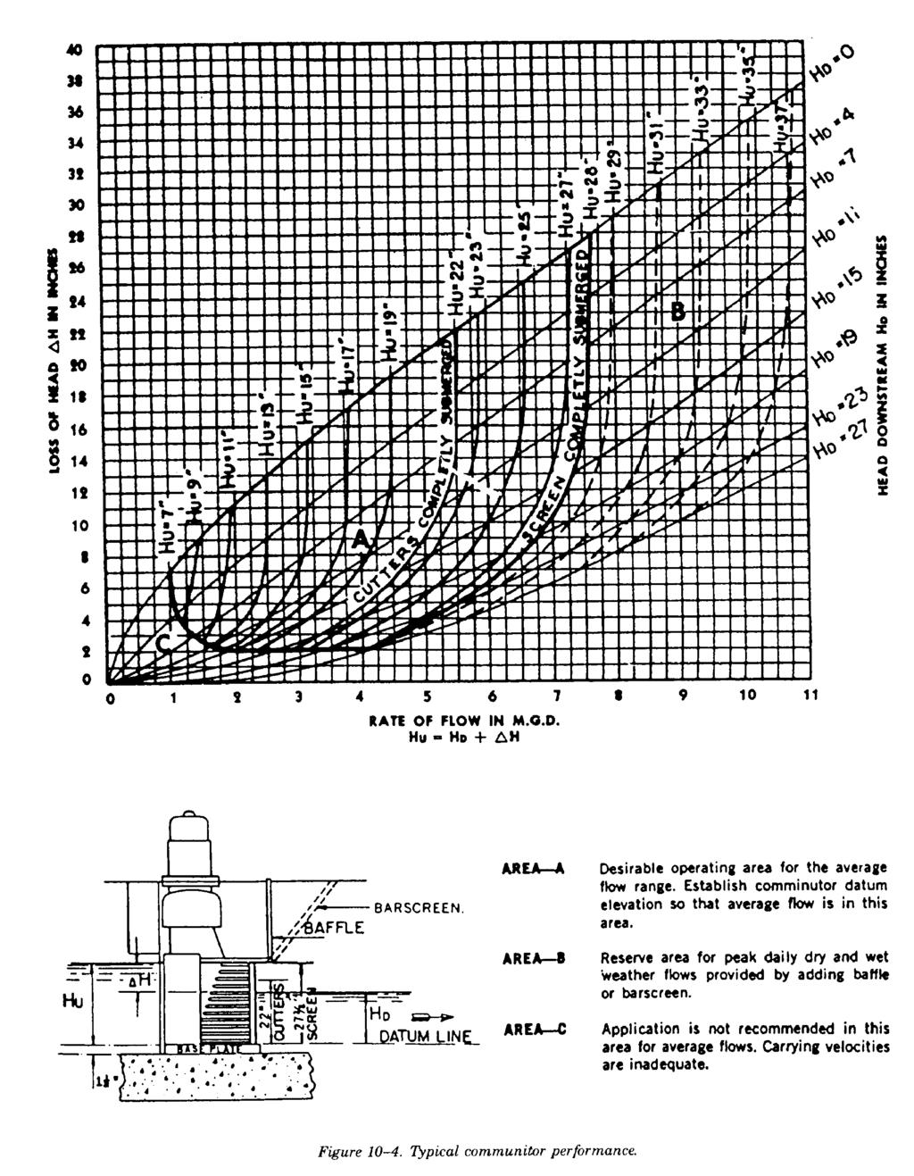
5 (6) Design procedure. Select bar size and spacing and determine efficiency factor. Determine number of units desired. Divide total maximum daily flow or total maximum storm flow by the number of screens desired to obtain maximum flow per screen. The procedure is then as follows: cfs 2 Maximum daily flow in mgd Maximum daily flow in cfs. Maximum storm flow in mgd = Maximum storm flow in cfs. = Net area through bars for maximum daily flow. cfs = Net area through bars for maximum storm flow. 3 Whichever of the above gives the larger value shall be used for design. Net area in sq.ft. Efficiency coefficient for bars Minimum width of bar rack = 2 ft; maximum width = 4 ft. Channel cross§ion wet area Maximum desired width or depth ' Gross area or channel cross§ion wet area. ' Corresponding depth or width. The figures are based on recessing channel walls 6 inches each side for chain tracks and screen frame. The overall width of screen frame is 12 inches greater than width of bar rack. If it is not possible to recess the wall, the channel should be made 1 foot wider than calculated above Comminuting devices a. Description and function. Comminuting devices are shredders which incorporate mechanisms that cut the retained material without removing it from the sewage flow. Comminutors are protective devices for the plant and also provide a means for reducing odors, flies and unsightliness often found around other coarse-screening devices. However; solids from a comminutor produce more scum at the digesters. Comminutors are generally located between grit chambers and the primary settling tanks. b. Design basis. Comminutors will be required in locations where the removal of screenings will be difficult. Comminutors are available commercially; their design consists basically of screening device and cutting device (fig 10-3). More recently, "in-line" comminutors have been used to reduce the cost of structures for shredding solids. Each comminuting device must have a bypass for maintenance and repair purposes. The bypass will include a bar screen, described as coarse screens in paragraph 10-2a. Manufacturer s data and rating tables for these units will be consulted for recommended channel dimensions, capacity ranges, upstream and downstream submergence, and power requirements. Figure 10-4 illustrates a typical manufacturer's design data. 10-5
6 10-6
7 10-7
8 10-4. Grit chambers. a. Purpose. The primary purpose of grit chambers is to protect pumps and other mechanical equipment. They may not be required if surface runoff is excluded from the sanitary sewer system; however; current policy is to include grit chambers for equipment protection regardless of the nature of the sewer system. Silting occurs through improper joints, broken manholes, and other openings in the system even without contributing surface runoff. Grit chambers will be located ahead of pumps and comminuting devices. Coarse bar racks will be placed ahead of mechanically cleaned grit-removal facilities. There are two types of grit chambers: horizontal-flow and aerated. The first attempts at controlling the wastewater velocity so that grit would settle out were the use of horizontal-flow chambers designed to maintain the velocity as close to 7 feet per second as practical. This velocity will carry most of the smaller organic particles through the chamber and will tend to resuspend those that settle but will allow the heavier inorganic grit to settle out. In recent years, the aerated grit chamber has been more widely used because introducing oxygen into the wastewater early in the treatment process is beneficial and there is minimal head loss through the chamber; however, the increased operational and energy costs must be included in evaluating this option. b. Horizontal-flow grit chamber. (1) Design basis. Grit chambers will be designed for a controlled velocity of 1 foot per second (at the average rate of flow) in order to prevent settling of organic solids (at low rates of flow) and scouring (at high rates of flow). The velocities at these conditions will not vary more than 10 percent from the design velocity. A sample design is shown in appendix C. (2) Velocity control. Control of velocity within a grit chamber will be provided by a control section paced by a weir, a Parshall flume, or a Venturi flume. (a) The weir will be either a proportional weir, Parshall flume or Venturi flume. Appendix C contains formulations and tables for design parameters applicable to such flow-control devices. (b) A Parshall flume is effective in controlling the velocity through a grit chamber within reasonable limits if the width of the flume throat is narrow enough to cause wide variations in the depth of water for the expected range of flow rates. Appendix C includes formulations and parameters of design for Parshall flumes. One advantage of Parshall flume control is that it can serve for both metering and velocity control. (c) A Venturi flume of rectangular cross-section is effective for the control of velocity in a rectangular grit chamber. The design of the effluent channel and other structures below the flume must be such that the head loss between the grit chamber and the effluent channel is not less than one-third the difference in elevations of the upstream crest and flume floor. Formulation and related design parameters for Venturi flume control are presented in appendix C. (3) Design factors. Grit chambers will be designed for a controlled velocity of approximately 1 foot per second and a detention period of 45 seconds. The design of grit chambers and flow-control devices is discussed and illustrated in appendix C. (a) Horizontal surface area. To size a grit chamber with rectangular cross-section, first determine the horizontal surface area using equation 10-1: where: 10-8 A = QX, (eq 10-1) A = horizontal surface area (sq ft); Q = flow rate (cfs); X = settling rate of grit particle (sec per ft). (Assume X = 16.7 sec/ft for all military installations.)
9 D ' L VX TM /AFM 88-11, Volume III Assume a grit chamber width of 2 feet for flows less than 1 million gallons per day, and 2 to 4 feet for flows between 1 and 2 million gallons per day. For flows greater than 2 million gallons per day, divide the area calculated above by the assumed width to obtain the length of the channel. At a flow velocity of 1.0 foot per second, the depth of flow can be determined by equation 10-2: where: D = depth of flow (ft); L = length of channel (ft); V = flow velocity (fps); X = settling rate (sec/ft). (eq 10-2) The rectangular cross-section channel will be used in treatment plants with capacity less than 2 million gallons per day. The parabolic channel is costly and best suited to larger plants. Square grit chambers are sized as rectangular cross-section channel chambers; horizontal area is the basis of design. These units are best suited to flows greater than 2 million gallons per day. (b) Channel size. In channel grit chambers, the length will be designed to be 50 percent longer than theoretically required to allow for turbulence and outlet distribution. The floor of the chamber will be far enough below the weir crest to make allowance for the accumulation of about 2.5 cubic feet of grit every 10 days per million gallons of wastewater. This depth allowance will be not less than 2½ inches. The channels will be as narrow as possible without causing serious submergence of the crown of the inlet sewer. The effluent channel will be designed so that objectionable shooting velocities are not produced and submergence of the weir crest by tail water will not exceed permissible limits. c. Aerated grit chamber. When wastewater flows into an aerated grit chamber, the grit will settle at rates dependent on the size, specific gravity, and the velocity of roll in the tank. The variable rate of air diffusion is a method of velocity control which can be easily adjustable to different field conditions. The following design criteria are to be used: (1) Air rates. The air system should be designed to provide 8 cubic feet per minute per foot of grit chamber length. The design should allow the air rate to be controlled over a range. (2) Detention time. The chamber should be designed to have a detention time of 3 minutes at the maximum flow rate. (3) Geometry. The inlet and outlet should be placed to prevent short circuiting in the chamber. In addi tion, the inlet should introduce the wastewater directly into the circulation pattern caused by the air. The outlet should be at a right angle to the inlet with a baffle. A length to width ratio of 4:1 should be used. d. Quantity of grit. The following design values should be used to provide storage for the collected grit. These values, along with the anticipated frequency of grit removal, will determine the storage volume required. (1) Combined sewer system. For a sewer system carrying both stormwater and domestic wastewater, storage for 30 cubic feet of grit per million gallons of flow should be provided. (2) Separate sewer system. Storage for 10 cubic feet of grit per million gallons of flow should be included. e. Disposal of grit. Impervious surfaces with drains will be provided as grit-handling areas. If the grit is to be transported, the conveying equipment must be designed to minimize loss of material. Suitable drainage facilities must be provided for a screenings-collection platform and for storage areas. Grit disposal will be in a sanitary landfill. 10-9
10 10-5. Dissolved air flotation. Flotation is a unit process whereby particulate matter is separated from a wastewater, causing the matter to float to the liquid surface. Criteria are provided in the EPA Manual 625/ Dissolved air flotation units will not be installed without permission from HQDA (DAEN-ECE-G) WASH DC for Army projects or HQ USAF/LEEE WASH DC for Air Force projects. Permission will be granted only when adequate laboratory or pilot studies data are available and when adequate justification for the additional maintenance and operational labor requirements is provided Wastewater flocculation. Flocculation units will be used and will immediately precede clarification units when a chemical precipitation process is employed as part of primary, secondary, or advanced wastewater treatment schemes. a. Methods. Porous diffuser tubes or plates are commonly used for air agitation; but perforated pipes, impingement diffusers, jet diffusers, or helix-type diffusers may also be used for air flocculation. Mechanical flocculation is achieved by revolving or reciprocating paddles, radial-flow turbine impellers, or draft tubes. In typical situations, mechanical aerators (vertical draft tube type) will be used in single tanks arranged for cross flow. b. Design factors. Mechanical and air flocculation units for domestic wastewater will be designed for 30 minutes of flocculation detention time followed by a clarifier with surface settling rates of 800 gallons per day per square foot. The air requirement for flocculation is 0.1 standard cubic feet per gallon at 30 minutes of detention time. To insure proper agitation, air will be supplied at 2.5 standard cubic feet per minute per linear foot of tank channel. The number and size of air diffusers are determined by dividing the total air requirement by the optimum air diffusion rate per unit (4.0 cubic feet per minute per square foot of porous diffuser area). Water depths vary from 8 to 13 feet. In rectangular tanks, the ratio of length to width will be 3:1 For mechanical flocculation, revolving paddles may be either horizontal or vertical. Peripheral-paddle speed should be kept in the range of 1.0 to 3.0 feet per second to minimize deposition and yet avoid destruction of the flocs. Table 10-2 presents values for design factors to be used in designing typical sewage treatment plants. c. Power Requirements. To compute the power requirements and velocity gradient requirements, the following formula should be used: 10-10
11 Typical values of G for a detention time of 15 to 30 minutes vary from 20 to 75 second. Figure 10-5 _1 is supplied to aid the designer in determining the horsepower requirement for flocculation systems. To use the figure, select G and detention time desired. (Note: flocculation tank volume can be determined from the design flow rate and the detention time.) Enter chart at detention time and find power. Correct by multiplying by the appropriate factor contained in the table accompanying the figure
12 10-12
Introduction to Preliminary Wastewater Treatment
 Introduction to Preliminary Wastewater Treatment Course No: C02-033 Credit: 2 PDH J. Paul Guyer, P.E., R.A., Fellow ASCE, Fellow AEI Continuing Education and Development, Inc. 9 Greyridge Farm Court Stony
WASTEWATER TREATMENT (1)
") Wastewater Engineering (MSc program) WASTEWATER TREATMENT (1) Prepared by Dr.Khaled Zaher Assistant Professor, Public Works Engineering Department, Faculty of Engineering, Cairo University Wastewater Flow
Wastewater Engineering (MSc program) WASTEWATER TREATMENT (1) Prepared by Dr.Khaled Zaher Assistant Professor, Public Works Engineering Department, Faculty of Engineering, Cairo University Wastewater Flow
Sanitary and Environmental Engineering I (4 th Year Civil)
") Sanitary and Environmental Engineering I (4 th Year Civil) Prepared by Dr.Khaled Zaher Assistant Professor, Public Works Engineering Department, Faculty of Engineering, Cairo University Wastewater Flow
Sanitary and Environmental Engineering I (4 th Year Civil) Prepared by Dr.Khaled Zaher Assistant Professor, Public Works Engineering Department, Faculty of Engineering, Cairo University Wastewater Flow
14. SCREENS. in the Figure 8.1. BARS TROUGH
 1 14. SCREENS The primary treatment incorporates unit operations for removal of floating and suspended solids from the wastewater. They are also referred as the physical unit operations. The unit operations
Liquid Stream Fundamentals: Grit Removal
 FACT SHEET Liquid Stream Fundamentals: Grit Removal Grit removal is an essential component of the wastewater treatment process. Not only does the removal of grit help protect downstream equipment from
Domestic Waste Water (Sewage): Collection, Treatment & Disposal
: Collection, Treatment & Disposal") Domestic Waste Water (Sewage): Collection, Treatment & Disposal Sanitary sewers Storm water sewers Combined sewers Types of sewers: Types of collection system Building sewer/building connections:connected
Domestic Waste Water (Sewage): Collection, Treatment & Disposal Sanitary sewers Storm water sewers Combined sewers Types of sewers: Types of collection system Building sewer/building connections:connected
1. Overview 2 2. Definitions 2 3. Laboratory Testing Criteria 2. A. Laboratory Qualifications 2. B. Analysis of TSS Samples 2. C.
 New Jersey Department of Environmental Protection Laboratory Protocol to Assess Total Suspended Solids Removal by a Hydrodynamic Sedimentation Manufactured Treatment Device January 25, 2013 Contents 1.
Screening, Definition: The unit involved is called a screen.
 Screening, Definition: Screening is a unit operation that separates materials in and/or on water (found in different sizes) from water and from entering water treatment facilities and mains. The unit involved
Vortex Separator. May be more cost-effective pre-treatment devices than traditional wet or dry basins.
 Description Vortex separators: (alternatively, swirl concentrators) are gravity separators, and in principle are essentially wet vaults. The difference from wet vaults, however, is that the vortex separator
CHAPTER 12 TRICKLING FILTER PLANTS
 CHAPTER 12 TRICKLING FILTER PLANTS TM 5-814-3/AFM 88-11, Volume III 12-1. General considerations. Trickling filter plants have been justified by their low initial cost, low operating and maintenance costs,
Industrial Pretreatment WT - Intakes
 Preliminary Unit Operations and Processes Preliminary Treatment remove materials that will interfere with further treatment Physical size separation Bar racks Screens Size reduction Grinders Barminutor
1. Overview 2 2. Definitions 2 3. Laboratory Testing Criteria 2. A. Laboratory Qualifications 2. B. Analysis of TSS Samples 2. C.
 1 2 3 4 5 6 New Jersey Department of Environmental Protection Laboratory Protocol to Assess Total Suspended Solids Removal by a Filtration Manufactured Treatment Device January 18, 2013 7 8 9 10 11 12
Oak Orchard Wastewater Treatment Plant. Wet Weather Operating Plan
 Oak Orchard Wastewater Treatment Plant Wet Weather Operating Plan July 2014 TABLE OF CONTENTS Section 1 Introduction and Overview. 1 Section 2 Wet Weather Operational Strategy.3 a. Wet Weather Operation
INITIAL TREATMENT By Kenny Oyler. Headworks:
 The headworks of a wastewater treatment plant is the initial stage of a complex process.this process reduces the level of pollutants in the incoming domestic and industrial wastewater to a level that will
Definition separation of unstable and destabilized suspended solids from a suspension by the force of gravity
 SEDIMENTATION-1 TEKNOLOGI PENGOLAHAN LIMBAH Definition separation of unstable and destabilized suspended solids from a suspension by the force of gravity 1 Applications in Wastewater Treatment grit removal
ATTACHMENT 1 GENERAL FACILITY INFORMATION. BOD5 mg/l mg/l TSS mg/l mg/l NH3-N mg/l mg/l
 ATTACHMENT 1 GENERAL FACILITY INFORMATION 1. Facility Name: 2. Type of Facility: 3. Population Served: Present: Design: 4. Flow: Average Maximum Peak 5. Water Quality: Present Design Assumed Actual Source:
City of Hudson. Wastewater Treatment Plant Improvements. Columbia County, New York. Facility Plan. Delaware Engineering, P.C.
 City of Hudson Columbia County, New York Wastewater Treatment Plant Improvements Facility Plan Prepared By: Delaware Engineering, P.C. 28 Madison Avenue Extension Albany, New York 12203 (Phone) 518-452-1290
Waste Water treatment
 The Islamic University of Gaza Faculty of Engineering Civil Engineering Department Environmental Engineering (ECIV 4324) Instructor: Dr. Abdelmajid Nassar Lect. 24-25 Waste Water treatment 1 Composition
4.4.6 Underground Detention
 4.4.6 Underground Detention Limited Application Water Quality BMP Description: Detention storage located in underground pipe systems or vaults designed to provide water quantity control through detention
A NEW METHOD FOR EVALUATING PRIMARY CLARIFIERS Alex Ekster and Cristina Pena San Jose/Santa Clara Water Pollution Control Plant City of San Jose
 A NEW METHOD FOR EVALUATING PRIMARY CLARIFIERS Alex Ekster and Cristina Pena San Jose/Santa Clara Water Pollution Control Plant City of San Jose ABSTRACT A new method has been developed for evaluating
Physical water/wastewater treatment processes
 Physical water/wastewater treatment processes Tentative schedule (I) Week 1: Introduction Week 2: Overview of water/wastewater treatment processes Week 3: Major contaminants (Chemicals and pathogens) Week
WASTE WATER TREATMENT SYSTEM
 WASTE WATER TREATMENT SYSTEM Manual Coarse and Mechanical Fine Screens: We manufacture high quality screens that are widely used for removing suspended particles from the waste water. These screens are
Grit Collection & Classification Case Studies
 Grit Collection & Classification Case Studies OWEA 2010 Specialty Biosolids Specialty Workshop Brian F. McNamara, HRSD Definition of Grit Metcalf & Eddy 2 nd Edition 1979 grit, consisting of sand, gravel,
1 Construction The sewage treatment plant (STP) is to be an Icon-Septech Pty Ltd Turbojet 4000 as described below and as shown on the drawings.
 is to be an Icon-Septech Pty Ltd Turbojet 4000 as described below and as shown on the drawings.") 1 Construction The sewage treatment plant (STP) is to be an Icon-Septech Pty Ltd Turbojet 4000 as described below and as shown on the drawings. 2 Design Parameters Domestic sewage will be collected from
1 Construction The sewage treatment plant (STP) is to be an Icon-Septech Pty Ltd Turbojet 4000 as described below and as shown on the drawings. 2 Design Parameters Domestic sewage will be collected from
1 Construction The sewage treatment plant (STP) is to be an Icon-Septech Pty Ltd Turbojet 5000 as described below and as shown on the drawings.
 is to be an Icon-Septech Pty Ltd Turbojet 5000 as described below and as shown on the drawings.") 1 Construction The sewage treatment plant (STP) is to be an Icon-Septech Pty Ltd Turbojet 5000 as described below and as shown on the drawings. 2 Design Parameters Domestic sewage will be collected from
1 Construction The sewage treatment plant (STP) is to be an Icon-Septech Pty Ltd Turbojet 5000 as described below and as shown on the drawings. 2 Design Parameters Domestic sewage will be collected from
SETTLING REVIEW CHECKLIST
 SETTLING REVIEW CHECKLIST Water Quality Wastewater Technical Review and Guidance FACILITY NAME CONSULTING ENGINEER DATE Water/Wastewater/#5.73, May 2001 SITE INSPECTION (DATE & INSPECTOR) PLANNING OR DESIGN
Thornton Sewer Plant Operations Manual -DRAFT-
 Thornton Sewer Plant Operations Manual -DRAFT- February 2014 Prepared for: HOUSING AUTHORITY OF THE COUNTY OF SAN JOAQUIN P.O. BOX 447 421 S. EL DORADO STREET STOCKTON, CA 95203 Prepared by: BLACK WATER
Capability of the Aqua-Swirl Concentrator to Remove Trash from Stormwater Runoff
 Capability of the Aqua-Swirl Concentrator to Remove Trash from Stormwater Runoff June 27, 2012 The purpose of this document is to demonstrate the capability of the Aqua-Swirl Concentrator to capture trash
CHAPTER 5 SEWAGE PUMPS AND LIFT STATIONS
 15 October 1973 FM 5-163 CHAPTER 5 SEWAGE PUMPS AND LIFT STATIONS 5-1. General Pumps for lifting sanitary sewage, storm water, and plant-unit effluents are usually high-capacity, low-head types with large
1 Construction The sewage treatment plant (STP) is to be an Icon-Septech Pty Ltd Turbojet 2000 as described below and as shown on the drawings.
 is to be an Icon-Septech Pty Ltd Turbojet 2000 as described below and as shown on the drawings.") 1 Construction The sewage treatment plant (STP) is to be an Icon-Septech Pty Ltd Turbojet 2000 as described below and as shown on the drawings. 2 Design Parameters Domestic sewage will be collected from
1 Construction The sewage treatment plant (STP) is to be an Icon-Septech Pty Ltd Turbojet 2000 as described below and as shown on the drawings. 2 Design Parameters Domestic sewage will be collected from
SC-01 Surface Outlet and Baffle Sediment Basin
 Greenville County Technical Specification for: SC-01 Surface Outlet and Baffle Sediment Basin 1.0 Surface Outlet and Baffle Sediment Basin This Specification contains requirements for the design and construction
Table of Contents Introduction... 3
 1 Table of Contents Introduction... 3 1. Installation Instructions:... 5 2. First of all the Site evaluation... 5 2.1 Where the tank should be built?... 5 2.2 Pipework... 6 3. Construction of a French
Norwalk, CT Water Pollution Control Facility (WPCF) CSO Capacity and Treatment Evaluation. Subject: Task 3 Existing Grit Removal System Assessment
 CSO Capacity and Treatment Evaluation. Subject: Task 3 Existing Grit Removal System Assessment") A Technical Memorandum Date: Project: Norwalk, CT Water Pollution Control Facility (WPCF) CSO Capacity and Treatment Evaluation Subject: Task 3 Existing Grit Removal System Assessment This memorandum presents
A Technical Memorandum Date: Project: Norwalk, CT Water Pollution Control Facility (WPCF) CSO Capacity and Treatment Evaluation Subject: Task 3 Existing Grit Removal System Assessment This memorandum presents
Klickitat County. On-Site Sewage System. Construction Manual
 Homeowner OSS Design and Construction Guide Klickitat County On-Site Sewage System Construction Manual Minimum standards and recommendations expected for the construction of on-site wastewater treatment
Course: Wastewater Management
 Course: Wastewater Management Prof. M. M. Ghangrekar Questions 1 1. Describe advantages and disadvantages offered by the water carriage system. 2. What are the possible adverse effects when untreated or
CTB3365x Introduction to Water Treatment
 CTB3365x Introduction to Water Treatment W2c Primary sedimentation Jules van Lier The screened and de-gritted sewage is further conveyed towards the biological treatment step. Can we remove some part of
Palmer Wastewater Treatment Plant Environmental Impacts. A summary of the impacts of this treatment alternative are listed below:
 6.1.3 Environmental Impacts A summary of the impacts of this treatment alternative are listed below: 1. The Matanuska River will receive treated effluent as it currently does. 2. Effluent quality would
FULL SCALE LABORATORY EVALUATION OF STORMCEPTOR MODEL STC 450 FOR REMOVAL OF TSS
 FULL SCALE LABORATORY EVALUATION OF STORMCEPTOR MODEL STC 450 FOR REMOVAL OF TSS Brian Lee, Scott Perry AUTHORS: Stormwater Specialists, Imbrium Systems Corporation, 12 Madison Ave, Toronto, Ontario, M5R
Client: City of Pontiac Project Name: Regional WWTP Feasibility Location: Pontiac, MI Project Number: Issue Date: October 23, 2006
 Client: City of Pontiac Project Name: Regional WWTP Feasibility Location: Pontiac, MI Project Number: 13649553 Issue Date: October 23, 2006 Subject: WWTP Condition Assessment Auburn Plant 1. Grit Removal:
Chapter 6 STEP System Force Main Velocity Evaluation
 Chapter 6 STEP System Force Main Velocity Evaluation \\7348101\TOC.doc CHAPTER 6 STEP System Force Main Velocity Evaluation 6.1 INTRODUCTION The City s existing STEP (septic tank effluent pump) pumps currently
Economics, Design, and Operation of Sewage-Treatment Plants W. E. Ross
 Economics, Design, and Operation of Sewage-Treatment Plants W. E. Ross Superintendent, Treatment Plant Richmond, Indiana In view of all the stress placed on post-war planning and construction, it was thought
SAFL Baffle Research Summary
 SAFL Baffle Research Summary Four years of research was conducted to develop and test the SAFL Baffle. The research took place at the University of Minnesota s St. Anthony Falls Laboratory and was funded
TEMPORARY SEDIMENT TRAP CODE
 ILLINOIS URBAN MANUAL PRACTICE STANDARD TEMPORARY SEDIMENT TRAP CODE 960 Source: DEFINITION A small temporary stormwater storage structure designed to trap sediment. PURPOSE The purpose of this practice
Study and Modification of Sewage Treatment Plant, at Jaspur
 IJIRST International Journal for Innovative Research in Science & Technology Volume 4 Issue 10 March 2018 ISSN (online): 2349-6010 Study and Modification of Sewage Treatment Plant, at Jaspur Arnab Biswas
Learning objectives. Upon successful completion of this lecture, the participants will be able to:
 Solomon Seyoum Learning objectives Upon successful completion of this lecture, the participants will be able to: Describe and perform the required step for designing sewer system networks Outline Design
DRIP EMITTER SYSTEM STUDY GUIDE
 DRIP EMITTER SYSTEM STUDY GUIDE Minimum Criteria for Pressurized Subsurface Absorption Fields Utilizing Emitters. Subsurface systems utilizing emitters may be used in lieu of conventional or other alternative
HUBER Sewerage Program
 HUBER Sewerage Program Machines and system solutions for stormwater treatment and sewer system management Equipment and system solutions for application in combined and separated sewer systems Advanced
When confronted with increasing peaking. Managing the deluge
 Located on more than 121 ha (300 ac) of land, the Trinity River Authority (Dallas) Central Regional Wastewater water resource recovery facility is an advanced secondary treatment facility and a winner
A signed statement from the manufacturer listing the protocol requirements and indicating that all of the requirements were met or exceeded.
 Protocol for Manufactured Hydrodynamic Sedimentation Devices for Total Suspended Solids Based on Laboratory Analysis Dated August 5, 2009, Revised December 15, 2009 The New Jersey Stormwater Management
PERKFILTER. Design Guide
 PERKFILTER Design Guide TABLE OF CONTENTS Description Function Treatment Processes System Hydraulics System Sizing PerkFilter Configurations Inspection and Maintenance Requirements Verification and Approvals
401 Sanitary Sewer System Design Criteria. The following additional design requirements shall also apply:
 SECTION 400 SANITARY SEWER SYSTEM The design of sanitary sewers shall be in conformance with the applicable sections of the State of Washington, Department of Ecology manual, Criteria for Sewage Works
Module 9 : Sewage And Storm water Pumping Stations. Lecture 11 : Sewage And Storm water Pumping Stations
 1 P age Module 9 : Sewage And Storm water Pumping Stations Lecture 11 : Sewage And Storm water Pumping Stations 2 P age 9.1 Introduction There are certain locations where it is possible to convey sewage
AERATED POND REVIEW CHECKLIST
 Water Quality AERATED POND REVIEW CHECKLIST Wastewater Technical Review and Guidance FACILITY NAME Water/Wastewater/#5.04, May 2001 DATE CONSULTING ENGINEER SITE INSPECTION (DATE & INSPECTOR) PLANNING
Chapter 9 Sanitary Sewers
 Chapter 9 Sanitary Sewers I:\AD\030\U30\U30009.docx 4-8-16 Section 9.1 Topic General Requirements Chapter 9 Sanitary Sewers Page 9-1 9.2 Plan Submittals 9-1 9.3 Determination of Flow 9-1 9.4 Facility Design
Chapter 5 Existing Wastewater Facilities
 Chapter 5 Existing Wastewater Facilities \\7348101\TOC.doc CHAPTER 5 Existing Wastewater Facilities 5.1 INTRODUCTION Lacey s wastewater utility serves over 21,000 acres (33 square miles) of residential
A SIMPLE SOLUTION TO BIG SNAIL PROBLEMS - A CASE STUDY AT VSFCD S RYDER STREET WASTEWATER TREATMENT PLANT
 A SIMPLE SOLUTION TO BIG SNAIL PROBLEMS - A CASE STUDY AT VSFCD S RYDER STREET WASTEWATER TREATMENT PLANT Timothy R. Tekippe, P.E.,* Robert J. Hoffman, P.E.,* Ronald J. Matheson,** Barry Pomeroy** *Carollo
Sanitary Sewer Systems. Sewage Collection System. Types of Sewage 10/12/2016. General Overview
 Sanitary Sewer Systems General Overview Sewage Collection System Pipes Pumping stations Maintenance entry points manholes Types of Sewage Sanitary Domestic sewage: human wastes and washwater from public
4.28 Underground Detention
 4.28 Underground Detention Detention Structural Stormwater Control Description: Detention storage located in underground tanks or vaults designed to provide water quantity control through detention and/or
Effluent Conveyance. Paul Trotta, P.E., Ph.D. Justin Ramsey, P.E. Chad Cooper
 Effluent Conveyance Paul Trotta, P.E., Ph.D. Justin Ramsey, P.E. Chad Cooper University Curriculum Development for Decentralized Wastewater Management 1 NDWRCDP Disclaimer This work was supported by the
Utilizing ScaleBlaster to Reduce Lime Scale Build-up in an Industrial Wastewater Treatment Plant
 Utilizing ScaleBlaster to Reduce Lime Scale Build-up in an Industrial Wastewater Treatment Plant Documented by The Village of Sauget Physical/Chemical Plant May, 2015 Purpose Case Study: Utilizing ScaleBlaster
CITY OF BELTON, MISSOURI WWTF FACILITY PLAN UPDATE TECHNICAL MEMORANDUM NO. 1 WWTF FLOW PROJECTIONS AND PROJECT PHASING. FINAL September 2012
 CITY OF BELTON, MISSOURI WWTF FACILITY PLAN UPDATE TECHNICAL MEMORANDUM NO. 1 WWTF FLOW PROJECTIONS AND PROJECT PHASING FINAL September 2012 903 E. 104TH STREET, SUITE 320 KANSAS CITY, MISSOURI 64131 P.
Woodford County Health Department 1831 S. Main Street, Eureka, IL Phone: (309) Fax: (309)
 Fax: (309)") Woodford County Health Department 1831 S. Main Street, Eureka, IL 61530 Phone: (309) 467-3064 Fax: (309) 467-5104 www.woodfordhealth.org APPLICATION/PERMIT FOR PRIVATE SEWAGE DISPOSAL SYSTEM FEE: $225.00
Woodford County Health Department 1831 S. Main Street, Eureka, IL 61530 Phone: (309) 467-3064 Fax: (309) 467-5104 www.woodfordhealth.org APPLICATION/PERMIT FOR PRIVATE SEWAGE DISPOSAL SYSTEM FEE: $225.00
ACTIVITY: Dewatering Operations AM 12
 Targeted Constituents Significant Benefit Partial Benefit Low or Unknown Benefit Sediment Heavy Metals Floatable Materials Oxygen Demanding Substances Nutrients Toxic Materials Oil & Grease Bacteria &
/ Marley MARPAK Modular Biomedia /
 / Marley MARPAK Modular Biomedia / The Marley MARPAK Difference SPX Cooling Technologies is a world leader in the design, manufacturing and construction of cooling products. The design and production of
Design and Maintenance Considerations for SNOUT Stormwater Quality Systems
 Design and Maintenance Considerations for SNOUT Stormwater Quality Systems Background: The SNOUT system from Best Management Products, Inc. (BMP, Inc.) is based on a vented hood that can reduce floatable
Wastewater Collection. (Sewer Alternatives)
") Wastewater Collection (Sewer Alternatives) Sewer Basics Collection and transport of wastewater from each home/building to the point where treatment occurs. Wastewater Characterization Solids Liquids Pipe
Wastewater Collection (Sewer Alternatives) Sewer Basics Collection and transport of wastewater from each home/building to the point where treatment occurs. Wastewater Characterization Solids Liquids Pipe
Sediment Basin. Fe= (Depends on soil type)
") 3.9 Sediment Control Description: A sediment basin is an embankment with a controlled outlet that detains stormwater runoff, resulting in the settling of suspended sediment. The basin provides treatment
3.9 Sediment Control Description: A sediment basin is an embankment with a controlled outlet that detains stormwater runoff, resulting in the settling of suspended sediment. The basin provides treatment
PERFORMANCE OF FLOATING HORIZONTAL AERATORS IN AERATED LAGOONS AND OXIDATION DITCHES
 PERFORMANCE OF FLOATING HORIZONTAL AERATORS IN AERATED LAGOONS AND OXIDATION DITCHES PRESENTED ON WEDNESDAY, APRIL 4, 2001 AT THE TEXAS WATER 2001 ANNUAL CONFERENCE LARRY W. MOORE CIVIL ENGINEERING DEPARTMENT
Primary: Removal of a portion of the suspended solids and organic matter from the wastewater by gravity
 1 Preliminary: Removal of wastewater constituents such as rags, sticks, floatables, grit, and grease that may cause maintenance or operational problems with the subsequent processes Primary: Removal of
SPILL ESTIMATION. Not Just A Guess Anymore
 SPILL ESTIMATION Not Just A Guess Anymore SPILL ESTIMATION Under current regulations accurate spill estimation has become critical to the operation and maintenance of a sanitary collection system Reporting
Air Lift Pumps (Grit Pump) ST-027
 ST-027") Air Lift Pumps (Grit Pump) ST-027 I. Grit removal facilities at Gilroy/Morgan Hill Plant. a. Aerated grit chambers and appurtenant equipment. 1. 2 grit tanks 2. Effective volume 47,713 Gal each. 3. Aeration
Air Lift Pumps (Grit Pump) ST-027 I. Grit removal facilities at Gilroy/Morgan Hill Plant. a. Aerated grit chambers and appurtenant equipment. 1. 2 grit tanks 2. Effective volume 47,713 Gal each. 3. Aeration
Dissolved Oxygen (DO):
:") Section VIII Water Treatment- Introduction Dissolved Oxygen (DO): - The source of D.O in water is photosynthesis and aeration - It is one of important parameters to measure the water quality. - It gives
Section VIII Water Treatment- Introduction Dissolved Oxygen (DO): - The source of D.O in water is photosynthesis and aeration - It is one of important parameters to measure the water quality. - It gives
Final Drainage Report
 Thornton Electric Substation Project Final Drainage Report December 14, 2016 DRAFT Prepared for: Xcel Energy, 1800 Larimer Street, Suite 400, Denver, Colorado 80202 Prepared by: 350 Indiana Street, Suite
Report. Inflow Design Flood Control System Plan Belle River Power Plant East China, Michigan. DTE Energy Company One Energy Plaza, Detroit, MI
 Report Inflow Design Flood Control System Plan Belle River Power Plant East China, Michigan DTE Energy Company One Energy Plaza, Detroit, MI October 14, 2016 NTH Project No. 62-160047-04 NTH Consultants,
APPENDIX B SAND MOUND
 3701-29-15 1 I. Introduction APPENDIX B SAND MOUND All soil absorption components and technologies shall be designed and installed to meet the requirements of rule 3701-29-15 of the Administrative Code
Private Sewage Systems Standard of Practice Proposed Revisions
 Private Sewage Systems Standard of Practice Proposed Revisions The Government of Alberta is currently reviewing the Standard of Practice (SOP) for Private Sewage Systems. To this end, the Alberta government
13.8 SEWAGE TREATMENT FLOW SHEET
 1 13.7.5 Flow Patterns of Reactors The flow pattern in the reactors depends on mixing conditions in them. This mixing in tern depends upon the shape of the reactor, energy spent per unit volume of the
SEWER SYSTEM DESIGN GUIDELINES
 SEWER SYSTEM DESIGN GUIDELINES PART 1 GENERAL 1.1 GENERAL GUIDELINES A. The following sewer system design guidelines are based on Federal, State and Local health requirements, and the Berkeley County Water
Chapter 6 Sand Filtration Treatment Facilities
 Sand Filtration Treatment Facilities 6.1 Purpose This chapter presents criteria for the design, construction and maintenance of runoff treatment sand filters. Treatment sand filters are used to collect,
HUBER Sewerage Program
 WASTE WATER Solutions HUBER Sewerage Program Machines and system solutions for stormwater treatment and sewer system management Combined and Storm Water Treatment Innovative technology and solutions for
Providing Infrastructure Redundancy at the Rocky River WWTP. Timothy McCann AECOM Keith Bovard Rocky River WWTP
 Timothy McCann AECOM Keith Bovard Rocky River WWTP WWTP Infrastructure Redundancy Redundancy As NASA Would Say: A Backup Plan for the Backup Plan Nuclear Power Plant Wastewater Treatment Plant Page 3 Infrastructure
Standards for Soil Erosion and Sediment Control in New Jersey May 2012 STANDARD FOR SLOPE PROTECTION STRUCTURES. Definition
 STANDARD FOR SLOPE PROTECTION STRUCTURES Definition Structures to safely conduct surface runoff from the top of a slope to the bottom of the slope. Purpose The purpose of this practice is to convey storm
NC-PC Industry Day Pretreatment 101. Industrial Waste Impacts on POTW Treatment Processes. Dawn Padgett Operations Manager Charlotte Water
 NC-PC Industry Day Pretreatment 101 Industrial Waste Impacts on POTW Treatment Processes Dawn Padgett Operations Manager Charlotte Water NC-PC Industry Day Definitions BOD Amount of oxygen consumed by
IMPROVED BIO-TOWER TECHNOLOGY MUNICIPAL SEWAGE TREATMENT
 IMPROVED BIO-TOWER TECHNOLOGY FOR MUNICIPAL SEWAGE TREATMENT Regd. Office : Henabh Center, 1326, Shukrawar Peth, Off. Bajirao Road, PUNE : 411 002 (INDIA), Tel. : 24473299 (5 Lines) 24474696, (Voice Mail)
Fuzzy Filter: The Right Path for Graton Community Services District
 WWD Article Application in Action: Water Reuse Fuzzy Filter: The Right Path for Graton Community Services District First Lagoon Effluent Filtration with Compressible Media Filter for Water Reuse Application
Maintenance Procedures
 Maintenance Procedures Maintenance Record When a Terre Kleen unit is newly installed, frequent inspection is highly recommended. The design of the Terre Kleen unit permits easy inspection. It is recommended
Jensen Deflective Separator (JDS) Stormwater Treatment Unit
 Stormwater Treatment Unit") Jensen Deflective Separator (JDS) Stormwater Treatment Unit A Full Capture, Screening, Swirl-Concentrating, Stormwater Treatment Unit The Jensen Deflective Separator (JDS) is a fullcapture, screening,
Jensen Deflective Separator (JDS) Stormwater Treatment Unit A Full Capture, Screening, Swirl-Concentrating, Stormwater Treatment Unit The Jensen Deflective Separator (JDS) is a fullcapture, screening,
June 19, 2013 Annual OWEA Conference Steven Reese, P.E.
 June 19, 2013 Annual OWEA Conference Steven Reese, P.E. Solids Review Storage and Mixing Considerations Enhancing Mixing Case Studies Shake: Chopper Pump and Nozzles Rattle: Jet Mix and Nozzles Roll: Linear
Water and Wastewater Engineering Prof. C. Venkobacher Department of Civil Engineering Indian Institute of Technology, Madras Lecture-17
 Water and Wastewater Engineering Prof. C. Venkobacher Department of Civil Engineering Indian Institute of Technology, Madras Lecture-17 In the last class we were discussing about the wastewater treatment
Next-generation modeling tool helps you get the most from your clarifier
 Clarifier Proce Next-generation modeling tool helps you get the most from your clarifier Alonso Griborio, Paul Pitt, and John Alex McCorquodale 52 W E & T w w w. w e f. o r g / m a g a z i n e 2008 Water
INFRASTRUCTURE & OPERATION
 SECTION C: INFRASTRUCTURE & OPERATION Advice on completing this section is provided in the accompanying Guidance Note. C.1 Operational Information Requirements Provide a description of the plant, process
Contact the Jurisdictional Engineer for materials allowed by each jurisdiction.
 Design Manual Chapter 3 - Sanitary Sewers 3C - Facility Design 3C-1 Facility Design A. Capacity of Pipe Pipe sizes 15 inches and smaller should carry the peak flow at a depth of no more than 0.67 of the
The Wastewater Insight
 September 07 Volume 4.9 The Wastewater Insight RAIN RAIN GO AWAY Rain Rain go away How does rain impact the wastewater treatment plant? MYSTERY BUG OF THE MONTH We started this month out with a new Mystery
PART V - STORM DRAIN DESIGN CRITERIA
 PART V - STORM DRAIN DESIGN CRITERIA A. Hydrology Studies and Hydraulic Analyses 1. Drainage area master plans and calculations are to be submitted with all subdivision improvement plans, permit improvement
PART V - STORM DRAIN DESIGN CRITERIA
 PART V - STORM DRAIN DESIGN CRITERIA A. Hydrology Studies and Hydraulic Analyses 1. Drainage area master plans and calculations are to be submitted with all subdivision improvement plans, permit improvement
APPENDIX G HYDRAULIC GRADE LINE
 Storm Drainage 13-G-1 APPENDIX G HYDRAULIC GRADE LINE 1.0 Introduction The hydraulic grade line is used to aid the designer in determining the acceptability of a proposed or evaluation of an existing storm
Facilities Plan. Technical Memorandum No. TM-WW-7 Hydraulic Analysis and Effluent Pump Station
 City of St. Joseph, Missouri Hydraulic Analysis and Effluent Pump Station By Work Order No. 09-001 B&V Project 163509 May 20, 2010 Table of Contents 1.0 Executive Summary...1 2.0 Purpose of Study...2 3.0
CITY OF YUMA WASTEWATER TREATMENT PLANTS. Cactus Moon Education, LLC.
 CITY OF YUMA WASTEWATER TREATMENT PLANTS Wastewater Purify Processes Environment Influent Landfill Bacterial Micro-organism Biological Clarification Residual Anaerobic Methane Bio-Solids Vocabulary All
Chemical Treatment. Batch treatment required, flow through continuous treatment not allowed
 Chemical Treatment SE-11 Objectives EC SE TR WE NS WM Erosion Control Sediment Control Tracking Control Wind Erosion Control Non-Stormwater Management Control Waste Management and Materials Pollution Control
Wastewater Collection System
 WASTEWATER COLLECTION SYSTEM CE 370 1 Wastewater Collection System The function of the collection system is to collect the wastewater from residential, commercial, and industrial areas within the service