CFD Analysis of a Low Head Propeller Turbine with Comparison to Experimental Data By: Artem Ivashchenko, Mechanical Solutions, Inc.
|
|
|
- Barnaby Briggs
- 6 years ago
- Views:
Transcription


1 CFD Analysis of a Low Head Propeller Turbine with Comparison to Experimental Data By: Artem Ivashchenko, Mechanical Solutions, Inc. Edward Bennett, Mechanical Solutions, Inc.
2 CFD Analysis of a Low Head Propeller Turbine with Comparison to Experimental Data By: Artem Ivashchenko, P.E., and Edward M. Bennett, Ph.D. Mechanical Solutions, Inc., USA Prepared for: HydroVision 2017 ABSTRACT Mechanical Solutions, Inc. (MSI) was contracted to perform several CFD analyses of an axial hydroturbine, with the purpose of validating the experimental data obtained by a hydroturbine test loop. The turbine in question was an axial turbine with a generator integrated into the runner shroud, designed as a single unit that could be dropped into a suitably-sized pipe. Additionally, MSI was to suggest possible modifications to the turbine geometry based on the results of the CFD analyses. MSI employed two CFD codes, ANSYS CFX and STAR-CCM+, which were used to conduct several transient analyses, three of which are detailed in this paper. The results of the transient analyses revealed good correlation between the numerical predictions and the experimental data. Both codes closely predicted the pressures measured by the physical pressure taps in the turbine. However, both codes consistently overpredicted the torque extracted by the turbine, and, as a result, the turbine efficiency. The predictions from STAR-CCM+ for turbine efficiency were consistently closer to the experimental results than those made by CFX. The majority of the torque losses occurred in the annular cavity above the runner shroud formed by the generator, where viscous drag on the rotating surfaces nullified 12% of the torque produced by the runner blades at the target operating conditions. An effort should thus be made to minimize the shroud diameter and axial length of the runner portion of the generator to minimize the losses due to drag. On the other hand, the draft tube and stay vane sections represented relatively minor sources of pressure losses for this configuration, and the drag on the exposed shaft in the draft tube was minimal. 1
3 INTRODUCTION Historically, hydropower has been realized by the development of large-scale projects with high head, requiring significant environmental and capital costs. These opportunities are also limited in their availability. However, low head hydropower is less costly in terms of environmental effects and construction costs, and provides a plentiful source of power throughout the world. Additionally, low head hydropower can often utilize existing infrastructure, such as non-powered dams and canals, to further reduce the impact of extracting hydraulic power. Low head hydropower does not come without its challenges. As the installations are often smaller in size, highly efficient designs are required to provide adequate return on investment, and creative approaches are necessary to limit the hardware and installation costs. As such, it is imperative that accurate analytical modeling be employed to reduce the cost of development to meet these objectives. Mechanical Solutions, Inc. (MSI) was contracted to perform several CFD analyses of an axial hydroturbine tested in a loop, presented in Figure 1. The hydroturbine in question was designed as a single unit that could be fitted into a suitably-sized pipe, with the generator integrated into the runner shroud. The goal of the analyses was to validate the experimental data obtained from testing, and to suggest possible performance improvements to the turbine geometry. MSI was provided with the CAD models of the turbine geometry and several drawings of the test loop. These were used to model a section of the test loop from the inlet pipe up to but not including the elbow after the draft tube reducer, as highlighted in Figure 2.

4 Figure 1. Hydroturbine Test Loop Layout.
5 Figure 2. The Boundaries of the CFD Model.


6 ANALYTICAL METHODS Using several photos, drawings and the provided CAD models, the partial loop flowpath assembly was built in ANSYS DesignModeler, as presented in Figure 3. It was then imported into ANSYS Mechanical, where the CFD mesh was created, which consisted of tetrahedral elements in the free stream, and prismatic elements along the wall. An exception was the shroud seal leakage domain, which was meshed with hexahedral elements in the main flow. The mesh was then transferred to ANSYS CFX for analysis, and the CFX model is shown in Figure 4. Concurrently, the flowpath model was also imported into STAR-CCM+ and, using the same mesh sizings, was meshed with polyhedral elements in the free stream and prismatic elements along the wall. The shroud seal leakage domain, however, was imported directly from the CFX model as a completed mesh. The complete flowpath mesh for STAR-CCM+ is presented in Figure 5. Figure 3. The Flowpath Model in ANSYS DesignModeler.


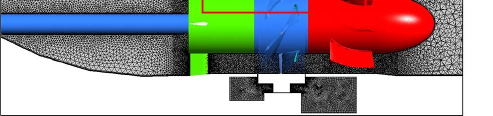
7 Figure 4. The Flowpath Mesh in ANSYS CFX.


8 Figure 5. The Flowpath Mesh in STAR-CCM+. Where appropriate, advantage was taken of the bilateral or periodic symmetry of various turbine domains during the meshing process, for example by meshing a single blade sector and then patterning and fusing the mesh. This process ensured mesh uniformity through the bladed sections of the geometry, as well as the mesh symmetry in the draft tube and the reducer. The mesh statistics for both CFD codes are presented in Table 1.
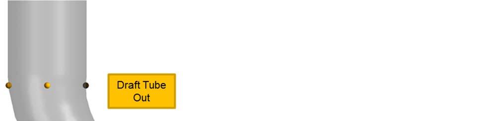
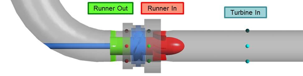
9 Table 1. Mesh Statistics for the Flowpath Models in CFX and STAR-CCM+. CFX STAR-CCM+ Domain Nodes Elements Vertexes Cells Inlet Extension 46, ,085 87,870 65,600 Nose Cone 67, , , ,630 Inlet Guide Vanes 1,419,670 4,946,151 1,481, ,267 Runner 1,276,095 4,283,530 4,589,435 1,434,930 Stay Vanes 788,120 2,795,320 2,944, ,788 Draft Tube 250, , , ,044 Draft Tube Extension 118, , , ,000 Reducer 59,874 74, ,164 35,478 Reducer Extension 118, ,000 90,092 68,400 Seal Leakage 4,693,680 4,558,320 4,693,680 4,558,320 TOTAL 9,308,517 18,223,314 15,286,887 8,024,457 Both models were solved with water as a single-phase, isothermal fluid at 30 C, using the Shear Stress Transport (SST) k-ω turbulence model. The SST model is a blend of the k-ω model in the boundary layer and the k-ε model in the free stream, based on the distance to the nearest surface and other flow variables. The blending is beneficial because the k-ε model is superior in the free stream conditions, where the k-ω model is too sensitive to the inlet turbulence properties, but is inferior to the k-ω model in predicting the onset of flow separation along the walls. In effect, the SST model combines the best of both worlds for CFD computations. STAR-CCM+ employed the segregated flow solver, which solves the flow equations for pressure and velocity components in an uncoupled manner, i.e. independently from one another, and then correlates the results using a predictor-corrector approach. Its use is appropriate for incompressible or mildly compressible flows, and is advantageous because it is more robust and it consumes less computational resources than the coupled flow model, which is the only model employed by CFX. Both CFD codes utilized scalable wall functions to simulate boundary layer effects, which is a common and accepted practice in industrial CFD applications. MSI endeavored to maintain a wall function non-dimensionalized distance between 10 and 50, which is the generally accepted practice. MSI then performed transient CFD analyses for several different flow conditions, as detailed in the next section. The timestep was set so that the runner domain rotated one degree per every timestep, i.e. 360 timesteps per one revolution. The mass flow rate was set at the inlet of the model, while static pressure was set at the outlet to roughly match the experimental results. The monitored values included the torque on rotating surfaces and the static pressure at the probe locations, set up to mimic the manifold rings in the test model, as shown in Figure 6. The transient analyses were run until the monitor value plots for torque and pressure were judged to have settled.

10 Figure 6. Pressure Measurement Locations.


11 CFD RESULTS MSI conducted several CFD validations in both CFX and STAR-CCM+, three of which are presented in this paper. For all analyses, MSI monitored the plots of relevant pump performance properties, such as mass flow, pressure and torque, to assess convergence, as presented in Figure 7. MSI also monitored static pressure at locations of physical pressure probes as described by the customer. The results for the target operating conditions are summarized in Table 2. Figure 7. Typical Convergence Plots.
12 Table 2. CFD Results Summary for the Target Operating Conditions. Turbine In Runner In Static Head Runner Out Draft Tube Out Total Head [m] [m] [m] [m] [m] STAR-CCM CFX Experiment Torque Ideal Water Power Shaft Power Efficiency [N-m] [kw] [kw] [n] STAR-CCM % CFX % Experiment % The results show good correlation between the experimental data and the pressure measurements predicted by the two CFD codes. Both codes underpredicted the total head of the turbine, although STAR-CCM+ was off by a smaller margin (1.3% versus 3.7% for CFX). The main discrepancy was encountered for the torque measurement predictions, as both CFX and STAR-CCM+ overpredicted the torque extracted by the turbine (by 7.1% and 6.8%, respectively), and consequently the turbine efficiency. It is MSI s opinion that some this overprediction is caused by the bearing losses, which are not modeled in the CFD analyses. The turbine used three sets of bearings: a spherical roller bearing at the IGV section, a deep groove ball bearing at the stay vane section, and an angular contact ball bearing near the dynamometer coupling. The total estimated bearing losses for this configuration were 400 W, which represented about 19% of the discrepancy in shaft power between the experimental data and the numerical predictions. Other mechanical sources of torque loss could include the losses in the dynamometer or in the stuffing box of the draft tube. In addition to mechanical losses, several other factors could be responsible for the difference in torque results. The most likely cause could be discrepancies in geometry between the CAD models and the experimental setup. The generator cavity was not an exact copy of the actual geometry, and minute differences in generator clearance could cause a profound change in torque results. Furthermore, surface roughness of the wetted faces could also play a role, because all the surfaces in the CFD analyses were modeled as hydraulically smooth. In reality, while MSI was informed that the rotor blades were machined smoothly, the same was not assuredly true for the rotor shroud. If the shroud or the generator cavities were rough, this would increase the viscous drag on the surfaces, and thus decrease the torque value, as discusses in more detail below.
13 Another reason for the discrepancy could be the inaccuracy of the turbulence models based on Reynolds-averaged Navier-Stokes (RANS) equations. To investigate that, MSI performed four more CFD analyses in STAR-CCM+ with different RANS turbulence models, as presented in Table 3. The results do not show a significant deviation from the original SST k-ω model in either head or torque. All other head values are within 1.7% of the 11 meters predicted by the SST model, and all other torque predictions are slightly higher, and thus further removed from the experimental value. An investigation of other more computationally intensive turbulence models, such as the Detached Eddy Simulation (DES) models or the Reynolds Stress Transport (RST) model, would thus be warranted. Table 3. CFD Results Summary for Other RANS Turbulence Models in STAR-CCM+. Turbine In Runner In Static Head Runner Out Draft Tube Out Total Head [m] [m] [m] [m] [m] SST k-ω Standard k-ω Realizable k-ε Standard k-ε Spalart-Allmaras Torque Ideal Water Power Shaft Power Efficiency [N-m] [kw] [kw] [n] SST k-ω % Standard k-ω % Realizable k-ε % Standard k-ε % Spalart-Allmaras % Yet another possibility is cavitation in either the turbine itself, or in the test loop pump. MSI did not have any information on the pump, so that possibility could not be investigated. As for the turbine, MSI was able to conduct a multi-phase CFD analysis to simulate possible cavitation inside the turbine runner domain. However, the cavitation analysis did not predict a significant change in turbine performance.

14 MSI also investigated the torque breakdown of the turbine to assess possible performance improvements. The results are presented in Table 4. The torque breakdown indicated that the main contributor to drag losses was the portion of the rotating shroud in the leakage path, with over 15% relative to the overall torque value. Therefore it would be prudent to seek ways to reduce the surface area in the leakage path on which the viscous forces operate, highlighted in dark orange in Figure 8. It should also be noted that the exposed shaft was not a significant source of drag in this configuration. Table 4. Torque Breakdown Summary for the Target Operating Conditions. CFX STAR-CCM+ Value [N-m] Percentage Value [N-m] Percentage Runner Blades % % Runner Hub % % Runner Shroud % % Exposed Shaft % % Leakage Surfaces % % TOTAL % % Figure 8. Selected Surfaces Contributing to the Drag on the Runner.


15 The velocity flowfield is presented in Figures 9 and 10. Both codes showed a significant recirculation region behind the stay vanes, as expected. There was also strong swirling flow in the generator cavity, which contributed to the large viscous drag on the runner. Figure 9. Turbine Velocity Flowfield in CFX (top) and STAR-CCM+ (bottom).

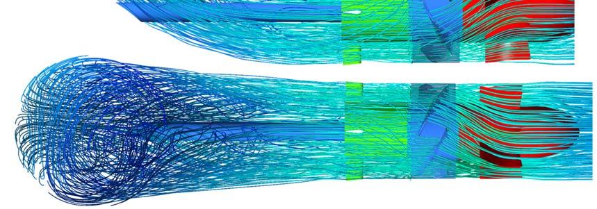

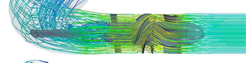
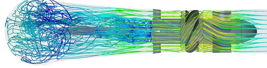
16 Figure 10. Turbine Velocity Streamlines in CFX (top) and STAR-CCM+ (bottom).

 (3) (4) (4a) (4b) (5) (6) (7) Outlet (10) Static Pressure [bar] 2.090 1.")
![966 1.687 1.643 1.040 0.888 0.962 1.129 1.035 Total Pressure [bar] 2.208 2.200 2.176 1.783 1.596 1.269 1.247 1.179 1.156 Mass Flow [kg/s] 466.0 466.0 466.0 5.8 5.8 466.0 466.0 466.1 466.](/docs-images/74/70123940/images/17-2.jpg "0 STAR-CCM+ Inlet (1) (3) (4) (4a) (4b) (5) (6) (7) Outlet (10) Static Pressure [bar] 2.037 1.913 1.634 1.535 0.956 0.829 0.884 1.054 0.957 Total Pressure [bar] 2.156 2.148 2.")
17 MSI also performed a relative comparison of the two codes in terms of their pressure predictions through the model flowpath. The pressure results were mass-flow averaged at every interface between the model regions, shown in Figure 11, and are presented in Table 5. The results correlate closely throughout, although STAR-CCM+ predicts a smaller total pressure drop through the draft tube than CFX does, and thus a larger draft tube effectiveness. Figure 11. Interface Measurement Locations. Table 5. Interface Measurements. CFX Inlet (1) (3) (4) (4a) (4b) (5) (6) (7) Outlet (10) Static Pressure [bar] Total Pressure [bar] Mass Flow [kg/s] STAR-CCM+ Inlet (1) (3) (4) (4a) (4b) (5) (6) (7) Outlet (10) Static Pressure [bar] Total Pressure [bar] Mass Flow [kg/s]
18 Tables 6 and 7 present the summary of two validations performed at a slower speed than previously, tagged as B and C. Both CFD codes did a reasonable job at matching the experimental results, although in these cases STAR-CCM+ was demonstrably better at estimating the turbine efficiency. In both cases, CFX underpredicted the total head of the turbine (by 4.6% and 3.4%), while STAR-CCM+ slightly overpredicted it (by 1.3% and 3.5%). As before, the two codes also overpredicted the torque (8.7% and 8.9% for STAR-CCM+, 11.9% and 9.4% for CFX). However, in its efficiency estimates, CFX was off by over 8 points in both cases, versus about 3 points for STAR-CCM+. Table 6. CFD Results Summary for Two Additional Validations. Validation B Turbine In Runner In Static Head Runner Out Draft Tube Out Total Head [m] [m] [m] [m] [m] STAR-CCM CFX Experiment Torque Ideal Water Power Shaft Power Efficiency Validation B [N-m] [kw] [kw] [n] STAR-CCM % CFX % Experiment % Validation C Turbine In Runner In Static Head Runner Out Draft Tube Out Total Head [m] [m] [m] [m] [m] STAR-CCM CFX Experiment Torque Ideal Water Power Shaft Power Efficiency Validation C [N-m] [kw] [kw] [n] STAR-CCM % CFX % Experiment %
19 Table 7. Torque Breakdown Summary for Two Additional Validations. CFX STAR-CCM+ Validation B Value [N-m] Percentage Value [N-m] Percentage Runner Blades % % Runner Hub % % Runner Shroud % % Exposed Shaft % % Leakage Surfaces % % TOTAL % % CFX STAR-CCM+ Validation C Value [N-m] Percentage Value [N-m] Percentage Runner Blades % % Runner Hub % % Runner Shroud % % Exposed Shaft % % Leakage Surfaces % % TOTAL % %
20 CONCLUSIONS AND RECOMMENDATIONS 1. Several transient CFD analyses were completed to evaluate the hydroturbine test loop flowpath geometry. Two CFD codes were used in this effort, ANSYS CFX and Star- CCM+, which revealed good correlation between the two codes and the experimental test data. 2. Both codes provided close predictions for the pressures measured by the physical pressure taps in the turbine. However, both codes consistently overpredicted the torque extracted by the turbine. About 20% of that overprediction was due to the bearing losses not being accounted for in the CFD analyses. 3. As a result of the torque overprediction, the codes also overpredicted the turbine efficiency. The predictions from STAR-CCM+ were consistently closer to the experimental results than those made by CFX. 4. Aside from mechanical losses, other factors that can cause the torque discrepancy are, in order from more likely to less likely: the geometry differences between CAD model and test model (most significantly the generator clearance), surface roughness of the test model (CFD analyses were performed with hydraulically smooth surfaces), trapped air in the test loop or inlet conditions with added turbulence or swirl. 5. Additional analyses using four other RANS turbulence models did not reveal a significant difference in results compared to the original SST k-ω turbulence model. An investigation using other more computationally intensive turbulence models, such as the Detached Eddy Simulation (DES) models or the Reynolds Stress Transport (RST) model, would thus be warranted. 6. The majority of the torque losses occurred in the annular cavity formed by the generator, where viscous drag on the external surfaces of the runner represented a 12% loss of the torque produced by the runner blades. An effort should thus be made to minimize the shroud diameter and axial length of the runner portion of the generator to minimize the losses due to drag. 7. The draft tube and stay vane sections represented relatively minor sources of pressure losses for this configuration.
21 AUTHORS Artem Ivashchenko, P.E., is a project engineer who, as a CFD analyst, has handled a variety of assignments involving investigative fluid dynamic analysis of a wide array of turbomachinery components, from centrifugal pumps and hydroturbines to compressors, medical devices and washing machines. He is a licensed engineer in the states of New Jersey and Colorado. Dr. Edward M. Bennett is the Vice President of Fluids Engineering at MSI. He has been involved with fluid dynamics and the aero/hydrodynamic design of turbomachinery for the past thirty five years, including numerous Francis, Kaplan and Pelton hydroturbines. He graduated from the Naval Academy, and holds a Ph.D. in Fluid Mechanics from Johns Hopkins University. REFERENCES Spalart, P. R. and Allmaras, S. R., "A One-Equation Turbulence Model for Aerodynamic Flows", AIAA Paper , Wilcox C. D., Turbulence Modeling for CFD, 2nd Ed., DCW Industries, Menter, F. R., "Two-Equation Eddy-Viscosity Turbulence Models for Engineering Applications", AIAA Journal, 32 (8): , ANSYS/CFX Version 17 Users Manual. STAR-CCM+ Version 12 Users Manual.
Derivation of Global Parametric Performance of Mixed Flow Hydraulic Turbine Using CFD. Ruchi Khare, Vishnu Prasad and Sushil Kumar
 Derivation of Global Parametric Performance of Mixed Flow Hydraulic Turbine Using CFD Ruchi Khare, Vishnu Prasad and Sushil Kumar Ruchi Khare Vishnu Prasad Sushil Kumar Abstract: The testing of physical
An Experience with Simulation Modelling for Radial Flow Pump
 International Journal of Emerging Engineering Research and Technology Volume 3, Issue 11, November 2015, PP 23-28 ISSN 2349-4395 (Print) & ISSN 2349-4409 (Online) An Experience with Simulation Modelling
International Journal of Scientific & Engineering Research, Volume 6, Issue 8, August ISSN
 International Journal of Scientific & Engineering Research, Volume 6, Issue 8, August-2015 232 Numerical Simulation for Unsteady Flow Analysis of Kaplan Turbine Vaibhav Chandrakar 1, Dr. Ruchi Khare 2
CFD Analysis of Pelton Runner
 International Journal of Scientific and Research Publications, Volume 4, Issue 8, August 2014 1 CFD Analysis of Pelton Runner Amod Panthee *, Hari Prasad Neopane **, Bhola Thapa ** * Turbine Testing Lab,
Recent approach to refurbishments of small hydro projects based on numerical flow analysis
 Recent approach to refurbishments of small hydro projects based on numerical flow analysis by Swiderski Engineering Ottawa, Canada Preamble Computational Fluid Dynamics (CFD) already established its strong
Computational Fluid Dynamic Analysis in De-staging of Centrifugal Pumps
 Computational Fluid Dynamic Analysis in De-staging of Centrifugal Pumps Vishnu R Nair 1, Shinas K V 2, Souganth Sugathan Manjhiparambil 3 Student, Department of Mechanical Engineering, IES College of Engineering,
Analysis of the Kaplan turbine draft tube effect
 IOP Conference Series: Earth and Environmental Science Analysis of the Kaplan turbine draft tube effect To cite this article: L Motycak et al 2010 IOP Conf. Ser.: Earth Environ. Sci. 12 012038 View the
Flow visualization at suction of a twin screw compressor
 Flow visualization at suction of a twin screw compressor A. Kovacevic, M. Arjeneh, S. Rane, N. Stosic, M. Gavaises, City University London Abstract Rotary twin screw machines are commonly used for handling
Evaluating Performance of Steam Turbine using CFD
 Evaluating Performance of Steam Turbine using CFD Sivakumar Pennaturu Department of Mechanical Engineering KL University, Vaddeswaram, Guntur,AP, India Dr P Issac prasad Department of Mechanical Engineering
INVESTIGATIONS ON PERFORMANCE OF A SAVONIUS HYDROKINETIC TURBINE
 INVESTIGATIONS ON PERFORMANCE OF A SAVONIUS HYDROKINETIC TURBINE Ph.D. THESIS by ANUJ KUMAR ALTERNATE HYDRO ENERGY CENTRE INDIAN INSTITUTE OF TECHNOLOGY ROORKEE ROORKEE-247667 (INDIA) AUGUST, 2017 INVESTIGATIONS
Comparison of experimental results of horizontal kaplan turbine with computational fluid dynamics
 University of Iowa Iowa Research Online Theses and Dissertations Summer 2012 Comparison of experimental results of horizontal kaplan turbine with computational fluid dynamics Vijaya Bijukchhe University
By Kimbal A. Hall, PE. Submitted to: WESTFALL MANUFACTURING COMPANY. May ALDEN RESEARCH LABORATORY, INC. 30 Shrewsbury Street Holden, MA 01520
 COMPUTATIONAL FLOW MODEL OF WESTFALL'S 36 3050 THREE STAGE MIXER TO BE INSTALLED IN THE PERCHLORATE BLENDING STATION FOR THE CITY OF REDLANDS, CALIFORNIA GFS-411507-1R2 By Kimbal A. Hall, PE Submitted
FLUID STRUCTURE INTERACTION MODELLING OF WIND TURBINE BLADES BASED ON COMPUTATIONAL FLUID DYNAMICS AND FINITE ELEMENT METHOD
 Proceedings of the 6th International Conference on Mechanics and Materials in Design, Editors: J.F. Silva Gomes & S.A. Meguid, P.Delgada/Azores, 26-30 July 2015 PAPER REF: 5769 FLUID STRUCTURE INTERACTION
Numerical Investigation of the Flow Structure in a Kaplan Draft Tube at Part Load
 IOP Conference Series: Earth and Environmental Science PAPER OPEN ACCESS Numerical Investigation of the Flow Structure in a Kaplan Draft Tube at Part Load To cite this article: R Maddahian et al 2016 IOP
International Journal of Research ISSN NO: Volume 7, Issue XII, December/2018. Page No:830
 A SCHEMATIC STUDY AND APPROACH OF A KAPLAN TURBINE VARYING FLUID FLOW RATE BY USING CFD ANALYSIS B.Vamsi Krishna Branch: Thermal engineering Roll no:14351d2121 Dr.Samuel George institute of Engg & Technology,
Improved Performance of Polypropylene Centrifugal Pump Using CFD
 Improved Performance of Polypropylene Centrifugal Pump Using CFD Gautam Nain 1, Rahul Malik 2 1 M.Tech Scholar, Department of Mechanical Engineering, PMCE, Sonipat 2 Head of Department,, Department of
OPTIMIZATION OF A MODEL FRANCIS TURBINE S PARAMETERS FOR THE MOST EFFICIENT PERFORMANCE CASE
 16 th International Conference on Clean Energy (ICCE-2018) 9-11 May 2018, Famagusta, N. Cyprus OPTIMIZATION OF A MODEL FRANCIS TURBINE S PARAMETERS FOR THE MOST EFFICIENT PERFORMANCE CASE Deniz Sarper
Hydraulic Machines, K. Subramanya
 Hydraulic Machines power point presentation Slides has been adapted from Hydraulic Machines, K. Subramanya 2016-2017 Prepared by Dr. Assim Al-Daraje 1 Chapter (1 Part 1) Prepared by Dr. Assim Al-Daraje
Research Article Research on Pump Volute Design Method Using CFD
 Rotating Machinery Volume 211, Article ID 136, 7 pages doi:1.1155/211/136 Research Article Research on Pump Volute Design Method Using CFD Sunsheng Yang, Fanyu Kong, and Bin Chen Research Center of Fluid
Blade number effect for a ducted wind turbine
 Journal of Mechanical Science and Technology (8) 984~99 Journal of Mechanical Science and Technology www.springerlink.com/content/738-494x DOI.7/s6-8-743-8 Blade number effect for a ducted wind turbine
CFD analysis of high speed Francis hydraulic turbines
 TRANSACTIONS OF THE INSTITUTE OF FLUID-FLOW MACHINERY No. 131, 2016, 111 120 Maciej Kaniecki a, Zbigniew Krzemianowski b CFD analysis of high speed Francis hydraulic turbines a Research and Development
2. In terms of operating as a machine, a sail boat energy from the air. A. Extracts B. Adds
 CHAPTER 12 1.Turbomachines are mechanical devices that either energy from a fluid, in the case of a turbine, or energy to a fluid, in the case of a pump. YOUR ANSWER: Extract, add 2. In terms of operating
Computational Fluid Dynamics-based Simulation to Francis Turbine under a Runaway Condition
 Computational Fluid Dynamics-based Simulation to Francis Turbine under a Runaway Condition Liying Wang, Bingyao Li, Weiguo Zhao and Qingjiao Cao Abstract When the turbine operates in a runaway condition,
A Computational Study on the Performance Improvement of Low-Speed Axial Flow Fans with Microplates
 Journal of Applied Fluid Mechanics, Vol. 10, No. 6, pp. 1537-1546, 2017. Available online at www.jafmonline.net, ISSN 1735-3572, EISSN 1735-3645. DOI: 10.18869/acadpub.jafm.73.243.27492 A Computational
UNIVERSITY OF ENGINEERING AND TECHNOLOGY TAXILA CIVIL ENGINEERING DEPARTMENT OUTCOME BASED EDUCATION CE-308: FLUID MECHANICS II
 UNIVERSITY OF ENGINEERING AND TECHNOLOGY TAXILA CIVIL ENGINEERING DEPARTMENT OUTCOME BASED EDUCATION CE-308: FLUID MECHANICS II Course Contents: Fluid flow in pipes Reynold's number and its significance.
Flow simulation and efficiency hill chart prediction for a Propeller turbine
 IOP Conference Series: Earth and Environmental Science Flow simulation and efficiency hill chart prediction for a Propeller turbine To cite this article: T C Vu et al 2010 IOP Conf. Ser.: Earth Environ.
Australian Journal of Basic and Applied Sciences
 AENSI Journals Australian Journal of Basic and Applied Sciences ISSN:1991-8178 Journal home page: www.ajbasweb.com Numerical Investigation of the Aerodynamics of Three Blades Vertical Axis Wind Turbine
Engineering & Expertise Hydraulic Modeling. Computational fluid dynamics
 Engineering & Expertise Hydraulic Modeling Computational fluid dynamics Engineering & Expertise Total solution engineering increases operational efficiency Introduction Understanding fluid flow inside
Design and Simulation of Very Low Head Axial Hydraulic Turbine with Variation of Swirl Velocity Criterion
 International Journal of Fluid Machinery and Systems DOI: http://dx.doi.org/10.5293/ijfms.2014.7.2.068 Vol. 7, No. 2, April-June 2014 ISSN (Online): 1882-9554 Original Paper (Invited) Design and Simulation
CFD Modelling of Pump as Turbine with Various Number of Blade for Microhydro System
 CFD Modelling of with Various Number of Blade for Microhydro System Mohd Azlan Ismail 1, Al Khalid Othman 2, Hushairi Zen 3, Mohd Suffian Misran 4 1,2,3 Faculty of Engineering, University Malaysia Sarawak,
DESIGN OPTIMISATION OF CONICAL DRAFT TUBE OF HYDRAULIC TURBINE
 DESIGN OPTIMISATION OF CONICAL DRAFT TUBE OF HYDRAULIC TURBINE Dr. Ruchi Khare, Dr. Vishnu Prasad, Mitrasen Verma Department of Civil Engineering M.A. National Institute of Technology Bhopal,India ruchif4@rediffmail.com
SCORG TM Setup for CFD Simulation of Twin Screw Machines with STAR-CCM+
 SCORG V5.4, 2016 SCORG Setup for CFD Simulation of Twin Screw Machines with STAR-CCM+ SCORG is the CFD grid generation tool for rotary twin screw machines. The tool includes additional modules for designing
Cloud computing simulation for improvement of turbomachinery efficiency & renewable energy
 Cloud computing simulation for improvement of turbomachinery efficiency & renewable energy M. Andreoli, A. Arcidiacono EnginSoft S.p.A. R. Bergamin ZECO S.r.l Outline Fortissimo project Partners Turbomachinery
Investigation on pressure fluctuation in a Francis turbine with improvement measures
 IOP Conference Series: Earth and Environmental Science OPEN ACCESS Investigation on pressure fluctuation in a Francis turbine with improvement measures To cite this article: J J Feng et al 2014 IOP Conf.
Development of Design Tool for Low-Head Francis Turbine. * Corresponding author
 Proceedings of the International Symposium on Current Research in Hydraulic Turbines CRHT VI March 14, 2016, Turbine Testing Lab, Kathmandu University, Dhulikhel, Nepal Paper no. CRHT2016-20 Development
MODERN PRACTICES FOR MEASUREMENT OF GAS PATH PRESSURES AND TEMPERATURES FOR PERFORMANCE ASSESSMENT OF AN AXIAL TURBINE
 Review of the Air Force Academy No.1 (33)/2017 MODERN PRACTICES FOR MEASUREMENT OF GAS PATH PRESSURES AND TEMPERATURES FOR PERFORMANCE ASSESSMENT OF AN AXIAL TURBINE Daniel OLARU, Valeriu VILAG, Gheorghe
Optimum design on impeller blade of mixed-flow pump based on CFD
 Available online at www.sciencedirect.com Procedia Engineering 31 (2012) 187 195 International Conference on Advances in Computational Modeling and Simulation Optimum design on impeller blade of mixed-flow
Performance of a bulb turbine suitable for low prototype head: model test and transient numerical simulation
 IOP Conference Series: Earth and Environmental Science Performance of a bulb turbine suitable for low prototype head: model test and transient numerical simulation To cite this article: L Zhu et al IOP
CFD Analysis of Oil Flooded Twin Screw Compressors
 CFD Analysis of Oil Flooded Twin Screw Compressors Sham RANE, Ahmed KOVACEVIC, Nikola STOSIC City University London, Centre for Compressor Technology, London, EC1V 0HB, UK sham.rane@city.ac.uk July 11-14,
CFD ANALYSIS OF DROGUE ASSEMBLY FOR UNDERWATER APPLICATION
 2th Annual CFD Symposium, August 9-1, 218, Bangalore CFD ANALYSIS OF DROGUE ASSEMBLY FOR UNDERWATER APPLICATION KUNJUNNI M*, RONI FRANCIS, DIWAKAR V M, P. VINOD Naval Physical & Oceanographic Laboratory,
Aerodynamic Design of 2.5 MW Horizontal Wind Turbine Blade in Combination with CFD Analysis
 Aerodynamic Design of 2.5 MW Horizontal Wind Turbine Blade in Combination with CFD Analysis Seul-Ki Yeom *, Tae-Jin Kang *, Warn-Gyu Park 1) School of Mechanical Engineering, Pusan National University,
Numerical Investigation of the Aerodynamics of Three Blades Vertical Axis Wind Turbine having Movable Vanes
 Numerical Investigation of the Aerodynamics of Three Blades Vertical Axis Wind Turbine having Movable Vanes Kadhim H. Suffer 1, a,, Ryspek. U. 2,b 1, 2, 4 School of Manufacturing Engineering 1,2 University
INCOMPRESSIBLE FLOW TURBOMACHINES Design, Selection, Applications,
 INCOMPRESSIBLE FLOW TURBOMACHINES Design, Selection, Applications, George F. Round Professor Emeritus McMaster University Hamilton, Ontario Canada ELSEVIER BUTTERWORTH HEINEMANN Amsterdam Boston Heidelberg
Review of optimization of mixed flow impeller using Ansys CFX
 IOSR Journal of Mechanical and Civil Engineering (IOSR-JMCE) e-issn: 2278-1684,p-ISSN: 2320-334X, PP 12-16 www.iosrjournals.org Review of optimization of mixed flow impeller using Ansys CFX Prof. Prashant.S.
NUMERICAL ANALYSIS OF THE EFFECT OF SPLITTER BLADES ON DRAFT TUBE CAVITATION OF A LOW SPECIFIC SPEED FRANCIS TURBINE
 6 th IAHR International Meeting of the Workgroup on Cavitation and Dynamic Problems in Hydraulic Machinery and Systems, September 9-11, 2015, Ljubljana, Slovenia NUMERICAL ANALYSIS OF THE EFFECT OF SPLITTER
heat exchanger modelling for generator ventilation systems
 heat exchanger modelling for generator ventilation systems This paper discusses how the heat exchanger/cooler is modelled using CFD (Computational Fluid Dynamics) as a porous medium and the associated
EVALUTION OF EROSION WEAR OF CETRIFUGAL PUMP USING CFD
 EVALUTION OF EROSION WEAR OF CETRIFUGAL PUMP USING CFD Satish kumar Department of Mechanical Engineering, Thapar Institute of Engineering and Technology, (India) ABSTRACT Centrifugal pumps are extensively
Francis Turbine Upgrade for the Lushui Generating Station by Using Computational Fluid Dynamics - A Case Study
 Francis Turbine Upgrade for the Lushui Generating Station by Using Computational Fluid Dynamics - A Case Study J. Huang, Ph.D., Hydraulic Energy Group, Sustainable Buildings and Communities, CANMET Energy
Chapter 5 1. Hydraulic Pumps (pp , Gorla & Khan; Wiki)
") Chapter 5 1. Hydraulic Pumps (pp. 47 90, Gorla & Khan; Wiki) 1. Two Basic Categories of Pumps Positive Displacement (PD) Pumps A positive displacement pump causes a fluid to move by trapping a fixed amount
Chapter 5 1. Hydraulic Pumps (pp. 47 90, Gorla & Khan; Wiki) 1. Two Basic Categories of Pumps Positive Displacement (PD) Pumps A positive displacement pump causes a fluid to move by trapping a fixed amount
Improving Efficiency of Submersible Pump Impeller of Mixed Flow Type by Design Modification through CFD Analysis
 Improving Efficiency of Submersible Pump Impeller of Mixed Flow Type by Design Modification through CFD Analysis Naveen Nagalinga Lohar 1, Prof. S A Janawade 2. 1Department of Mechanical Engineering (M.Tech
Alpha College of Engineering
 Alpha College of Engineering Department of Mechanical Engineering TURBO MACHINE (10ME56) QUESTION BANK PART-A UNIT-1 1. Define a turbomahcine. Write a schematic diagram showing principal parts of a turbo
Testing of a 1 kw-class Cryogenic Turboalternator
 426 Brayton Cryocooler Developments 1 Testing of a 1 kw-class Cryogenic Turboalternator D. Deserranno, A. Niblick, M. Zagarola Creare Hanover, NH 03755, USA ABSTRACT Future NASA missions will require hydrogen
Advanced Electric Submersible Pump Design Tool for Geothermal Applications
 Geothermal Resources Council s 36 th Annual Meeting Reno, Nevada, USA September 30 October 3, 2012 Advanced Electric Submersible Pump Design Tool for Geothermal Applications Xuele Qi, Norman Turnquist,
Available online at ScienceDirect. Procedia Engineering 105 (2015 )
") Available online at www.sciencedirect.com ScienceDirect Procedia Engineering 105 (2015 ) 692 697 6th BSME International Conference on Thermal Engineering (ICTE 2014) Adjacent wake effect of a vertical
Available online at www.sciencedirect.com ScienceDirect Procedia Engineering 105 (2015 ) 692 697 6th BSME International Conference on Thermal Engineering (ICTE 2014) Adjacent wake effect of a vertical
Application of CFD for Analyzing Quenching and Quench System Design. Andrew L. Banka
 Application of CFD for Analyzing Quenching and Quench System Design Andrew L. Banka Purpose Quenching - one of last (and more dramatic) steps in heat treat process Poor quench? Distortion Part to part
DESIGN-POINT, OFF-DESIGN MEANLINE PERFORMANCE ANALYSIS AND CFD COMPUTATIONS OF THE AXIAL TURBINE TO MICRO GASTURBINE ENGINE
 Journal of KONES Powertrain and Transport, Vol. 16, No. 4 2009 DESIGN-POINT, OFF-DESIGN MEANLINE PERFORMANCE ANALYSIS AND CFD COMPUTATIONS OF THE AXIAL TURBINE TO MICRO GASTURBINE ENGINE Wojciech Bar Rzeszow
Discovering Better Designs Faster for Centrifugal Pumps
 Discovering Better Designs Faster for Centrifugal Pumps Presentation Outline Motivation for Modeling & Simulation Improving pump performance within a short development cycle The process/workflow and the
AEROTHERMAL PERFORMANCE OF PARTIAL AND CAVITY SQUEALER TIP IN A LINEAR TURBINE CASCADE
 Journal of Thermal Engineering CONFERENCE ON ADVANCES IN MECHANICAL ENGINEERING ISTANBUL 2016 ICAME2016 11-13 May 2016, Yildiz Technical University, Istanbul, Turkey AEROTHERMAL PERFORMANCE OF PARTIAL
Computational Fluid Dynamics Technology Applied to High Performance, Reliable Axial Compressors for Power Generation Gas Turbines
 Mitsubishi Heavy Industries Technical Review Vol. 52 No. 1 (March 2015) 1 Computational Fluid Dynamics Technology Applied to High Performance, Reliable Axial Compressors for Power Generation Gas Turbines
Sediment Erosion in Hydro Turbines
 Sediment Erosion in Hydro Turbines Hari Prasad Neopane, PhD Associate Professor & Head Department of Mechanical Engineering Kathmandu University Nepal Outline of Presentation Status of Electricity Generation
The importance of optimising sump design for the reliable operation of rotodynamic pumps
 The importance of optimising sump design for the reliable operation of rotodynamic pumps Richard Brewis Project Engineer BHR Group Steve Graham Sales Director Bedford Pumps Ltd 02 Why is it important to
Hydraulic performance of a low specific speed centrifugal pump with Spanwise-Slotted Blades
 IOP Conference Series: Materials Science and Engineering OPEN ACCESS Hydraulic performance of a low specific speed centrifugal pump with Spanwise-Slotted Blades To cite this article: D X Ye et al 2013
Numerical investigation on effect of blade shape for stream water wheel performance.
 IOP Conference Series: Materials Science and Engineering PAPER OPEN ACCESS Numerical investigation on effect of blade shape for stream water wheel performance. To cite this article: N F Yah et al 2018
Appendix B. Glossary of Steam Turbine Terms
 Operator s Guide to General Purpose Steam Turbines: An Overview of Operating Principles, Construction, Best Practices, and Troubleshooting. Robert X. Perez and David W. Lawhon. 2016 Scrivener Publishing
T.E. (Mech., Mech. S/W) (Semester II) Examination, 2011 TURBOMACHINES (New) (2008 Pattern)
 (Semester II) Examination, 2011 TURBOMACHINES (New) (2008 Pattern)") *4063218* [4063] 218 T.E. (Mech., Mech. S/W) (Semester II) Examination, 2011 TURBOMACHINES (New) (2008 Pattern) Time : 3 Hours Marks : 100 Instructions : 1) Answer any three questions from each Section.
*4063218* [4063] 218 T.E. (Mech., Mech. S/W) (Semester II) Examination, 2011 TURBOMACHINES (New) (2008 Pattern) Time : 3 Hours Marks : 100 Instructions : 1) Answer any three questions from each Section.
PREDICTION OF PERFORMANCE OF GAS TURBINE OPERATING ON AIR USING 3D CFD
 International Journal of Mechanical Engineering and Technology (IJMET) Volume 8, Issue 1, January 2017, pp. 256 263, Article ID: IJMET_08_01_028 Available online at http://www.iaeme.com/ijmet/issues.asp?jtype=ijmet&vtype=8&itype=1
00046 Term-End Examination June, 2015
 No. of Printed Pages : 5 BIME-013 B.Tech. - VIEP - MECHANICAL ENGINEERING (BTMEVI) 00046 Term-End Examination June, 2015 BIME-013 : TURBO MACHINES Time : 3 hours Maximum Marks : 70 Note : Answer any five
Study of a Supercritical CO 2 Turbine with TIT of 1350 K for Brayton Cycle with 100 MW Class Output: Aerodynamic Analysis of Stage 1 Vane
 Study of a Supercritical CO 2 Turbine with TIT of 1350 K for Brayton Cycle with 100 MW Class Output: Aerodynamic Analysis of Stage 1 Vane Joshua Schmitt, Rachel Willis, David Amos, Jay Kapat Center for
NUMERICAL STUDY ON FILM COOLING AND CONVECTIVE HEAT TRANSFER CHARACTERISTICS IN THE CUTBACK REGION OF TURBINE BLADE TRAILING EDGE
 S643 NUMERICAL STUDY ON FILM COOLING AND CONVECTIVE HEAT TRANSFER CHARACTERISTICS IN THE CUTBACK REGION OF TURBINE BLADE TRAILING EDGE by Yong-Hui XIE *, Dong-Ting YE, and Zhong-Yang SHEN School of Energy
ACTIVE FLOW CONTROL OF VORTEX ROPE IN A CONICAL DIFFUSER
 ACTIVE FLOW CONTROL OF VORTEX ROPE IN A CONICAL DIFFUSER Ardalan Javadi * Department of Applied Mechanics, Chalmers University of Technology, SE-412 96, Göteborg, Sweden Håkan Nilsson Department of Applied
The Pennsylvania State University The Graduate School College of Engineering THE HISTORY AND DESIGN OF A RAPIDLY DEPLOYABLE
 The Pennsylvania State University The Graduate School College of Engineering THE HISTORY AND DESIGN OF A RAPIDLY DEPLOYABLE ADVANCED HUBLESS LOW HEAD HYDROPOWER TURBINE A Thesis in Mechanical Engineering
Research on the cavitation characteristic of Kaplan turbine under sediment flow condition
 IOP Conference Series: Earth and Environmental Science Research on the cavitation characteristic of Kaplan turbine under sediment flow condition To cite this article: L Weili et al 2010 IOP Conf. Ser.:
Design of Experiment Pressure Measurements Inside the Tokke Runner. * Corresponding author
 Proceedings of the International Symposium on Current Research in Hydraulic Turbines CRHT VI March 14, 2016, Turbine Testing Lab, Kathmandu University, Dhulikhel, Nepal Paper no. CRHT2016-16 Design of
Behaviour of Secondary Coolant Flow on the Turbine Blade Surface
 Proceedings of the 2 nd World Congress on Mechanical, Chemical, and Material Engineering (MCM'16) Budapest, Hungary August 22 23, 2016 Paper No. HTFF 124 DOI: 10.11159/htff16.124 Behaviour of Secondary
Numerical analysis of eccentric orifice plate using ANSYS Fluent software
 IOP Conference Series: Materials Science and Engineering PAPER OPEN ACCESS Numerical analysis of eccentric orifice plate using ANSYS Fluent software To cite this article: D Zahariea 2016 IOP Conf. Ser.:
Comparative Analysis of Different Orifice Geometries for Pressure Drop
 IJSTE - International Journal of Science Technology & Engineering Volume 2 Issue 10 April 2016 ISSN (online): 2349-784X Comparative Analysis of Different Orifice Geometries for Pressure Drop C. R. Sanghani
Effect of Orifice Plate Shape on Performance Characteristics
 IOSR Journal of Mechanical and Civil Engineering (IOSR-JMCE) e-issn: 2278-1684,p-ISSN: 2320-334X, Volume 13, Issue 4 Ver. VII (Jul. - Aug. 2016), PP 50-55 www.iosrjournals.org Effect of Orifice Plate Shape
International Journal of Scientific and Research Publications, Volume 8, Issue 8, August ISSN
 International Journal of Scientific and Research Publications, Volume 8, Issue 8, August 2018 314 Flow Analysis of Turgo Impulse Turbine for Low Head Power Plant Hnin Hnin Ei *, Myat Myat Soe ** * Department
Investigation of Rotating Instability in the Last Stage of Low Pressure Turbine during Low volume flow Operation
 Investigation of Rotating Instability in the Last Stage of Low Pressure Turbine during Low volume flow Operation Dilip Kumar Garg 1, Shrinivas Chambalwar 2, Jayant Sarode 3, Ajay Dhanopia 4 1 Department
Numerical Investigation of the Flow Dynamics of a Supersonic Fluid Ejector
 Proceedings of the International Conference on Heat Transfer and Fluid Flow Prague, Czech Republic, August 11-12, 2014 Paper No. 171 Numerical Investigation of the Flow Dynamics of a Supersonic Fluid Ejector
[Asif, 4(8): August, 2015] ISSN: (I2OR), Publication Impact Factor: 3.785
![[Asif, 4(8): August, 2015] ISSN: (I2OR), Publication Impact Factor: 3.785](/thumbs/89/97956162.jpg "[Asif, 4(8): August, 2015] ISSN: (I2OR), Publication Impact Factor: 3.785") IJESRT INTERNATIONAL JOURNAL OF ENGINEERING SCIENCES & RESEARCH TECHNOLOGY CFD ANALYSIS AND FABRICATION OF BLADE OF A HORIZONTAL AXIS WIND TURBINE USING DIFFERENT T. Mohammed Asif *, G. Praveen Kumar Yadav
IJESRT INTERNATIONAL JOURNAL OF ENGINEERING SCIENCES & RESEARCH TECHNOLOGY CFD ANALYSIS AND FABRICATION OF BLADE OF A HORIZONTAL AXIS WIND TURBINE USING DIFFERENT T. Mohammed Asif *, G. Praveen Kumar Yadav
International Symposium on Current Research in HydraulicTurbines DESIGN AND CFD ANALYSIS OF PICO HYDRO TURGO TURBINE
 Kathmandu University International Symposium on Current Research in HydraulicTurbines (CRHT-VII) DESIGN AND CFD ANALYSIS OF PICO HYDRO TURGO TURBINE Sudish Gyanwali 1*, Kush Kuikel 1 and Abinath Thapa
Development in Performance of Impeller used in Centrifugal Pump by using Computational Fluid Dynamics
 Development in Performance of Impeller used in Centrifugal Pump by using Computational Fluid Dynamics Nilesh N Patil Student Department Mechanical of Engineering D.K.T.E S Textile and Engineering Institute,
Tentative Study on Performance of Darriues-Type Hydroturbine Operated in Small Open Water Channel
 IOP Conference Series: Earth and Environmental Science OPEN ACCESS Tentative Study on Performance of Darriues-Type Hydroturbine Operated in Small Open Water Channel To cite this article: D Matsushita et
Principles of. Turbomachinery. Seppo A. Korpela. The Ohio State University WILEY A JOHN WILEY & SONS, INC., PUBLICATION
 Principles of Turbomachinery Seppo A. Korpela The Ohio State University WILEY A JOHN WILEY & SONS, INC., PUBLICATION CONTENTS Foreword xiii Acknowledgments xv 1 Introduction 1 1.1 Energy and fluid machines
ORCHID Turbine. Fluid-dynamic design and characterization of a mini-orc turbine for laboratory experiments
 Prof. ORCHID Turbine Fluid-dynamic design and characterization of a mini-orc turbine for laboratory experiments M. Pini, C. De Servi, M. Burigana, S. Bahamonde, A. Rubino, S. Vitale, P. Colonna ORC2017-14/09/2017
NUMERICAL ANALYSIS FOR DRAG REDUCTION IN COMMERCIAL BUSES
 e- ISS: 2278-1684, p-iss : 2320 334X UMERICAL AALYSIS FOR DRAG REDUCTIO I COMMERCIAL BUSES J. Godwin John 1, A.Muthuvel 2,. Prakash 3 1 (M.Tech ICE, HITS/ HIDUSTA University, IDIA) 2, 3 (Automobile Department,
Performance estimation on micro gas turbine plant recuperator
 Performance estimation on micro gas turbine plant recuperator Laura Alina STIKA 1, Jeni Alina POPESCU,1, Sorin Gabriel TOMESCU 1, Valeriu-Alexandru VILAG 1 Corresponding author 1 National Research and
The Effect of Solidity on a Tidal Turbine in Low Speed Flow
 The Effect of Solidity on a Tidal Turbine in Low Speed Flow T Hernández-Madrigal #1, A Mason-Jones #2, T O Doherty #3, DM O Doherty *4 # Cardiff Marine Energy Research Group, Cardiff University Queens
Optimisation of wastegate bypass flow reintroduction for increased turbine stage efficiency
 Optimisation of wastegate bypass flow reintroduction for increased turbine stage efficiency C. Hasler Cummins Turbo Technologies Advanced Technology Dept, England ABSTRACT A significant proportion of modern
Case Study and Numerical Analysis of Vibration and Runner Cracks for the Lipno I Hydroelectric Project
 IOP Conference Series: Earth and Environmental Science PAPER OPEN ACCESS Case Study and Numerical Analysis of Vibration and Runner Cracks for the Lipno I Hydroelectric Project To cite this article: J Zouhar
VALIDATION OF A CFD MODEL IN RECTANGULAR SETTLING TANKS
 Proceedings of the 13 th International Conference on Environmental Science and Technology Athens, Greece, 5-7 September 2013 VALIDATION OF A CFD MODEL IN RECTANGULAR SETTLING TANKS A. GKESOULI 1, A. I.STAMOU
Analysis of Centrifugal Pump Impeller Using ANSYS
 Analysis of Centrifugal Pump Impeller Using ANSYS Deepak E P 1, Dr.S.Sankar 2, Tedy Thomas 3, Sreejith K.V 4 M.Tech Scholar, Dept. of ME, NCERC, Pampady, Kerala, India 1 H.O.D, Dept. of ME, NCERC, Pampady,
Performance analysis of a counter-rotating tubular type micro-turbine by experiment and CFD
 IOP Conference Series: Earth and Environmental Science Performance analysis of a counter-rotating tubular type micro-turbine by experiment and CFD To cite this article: N J Lee et al 2012 IOP Conf. Ser.:
ISSN: [Nema* et al., 6(2): February, 2017] Impact Factor: 4.116
![ISSN: [Nema* et al., 6(2): February, 2017] Impact Factor: 4.116](/thumbs/87/96605485.jpg "ISSN: [Nema* et al., 6(2): February, 2017] Impact Factor: 4.116") IJESRT INTERNATIONAL JOURNAL OF ENGINEERING SCIENCES & RESEARCH TECHNOLOGY DESIGN AND EVALUATION OF PERFORMANCE OF CONICAL TYPE DRAFT TUBE WITH VARIATION IN LENGTH TO DIAMETER RATIO Umashankar Nema*, Dr.
IJESRT INTERNATIONAL JOURNAL OF ENGINEERING SCIENCES & RESEARCH TECHNOLOGY DESIGN AND EVALUATION OF PERFORMANCE OF CONICAL TYPE DRAFT TUBE WITH VARIATION IN LENGTH TO DIAMETER RATIO Umashankar Nema*, Dr.
Analysis of Flue Gas Flow Behavior in Economiser Duct Using Cfd
 Analysis of Flue Gas Flow Behavior in Economiser Duct Using Cfd Anand Kumar S Malipatil 1, Shivaraj 2 Department of Thermal Power Engineering, VTU-Gulbarga Abstract-- Energy saving and efficiency are the
CFD Analysis of a Mixture Flow in a Producer Gas Carburetor for optimizing the design configuration
 CFD Analysis of a Mixture Flow in a Producer Gas Carburetor for optimizing the design configuration T.R.Ani1 l, S.D.Ravi 2, M.Shashikanth 2, P.G.Tewari 3 and N.K.S.Rajan 4 l Research student, and Assistant
Thermodynamics of. Turbomachinery. Fluid Mechanics and. Sixth Edition. S. L. Dixon, B. Eng., Ph.D. University of Liverpool, C. A. Hall, Ph.D.
 Fluid Mechanics and Thermodynamics of Turbomachinery Sixth Edition S. L. Dixon, B. Eng., Ph.D. Honorary Senior Fellow, Department of Engineering, University of Liverpool, UK C. A. Hall, Ph.D. University
Effects of shaft supporting structure on performance test of axial flow fan
 IOP Conference Series: Materials Science and Engineering PAPER OPEN ACCESS Effects of shaft supporting structure on performance test of axial flow fan To cite this article: R Ma et al 2016 IOP Conf. Ser.:
Alden Turbine Development: Overview of Preliminary Engineering
 Alden Turbine Development: Overview of Preliminary Engineering November 16 th, 2010 Voith Hydro All rights reserved. Presentation Overview Engineering Overview Design Modifications Model Testing Mechanical