OPERA SAFETY CASE. Date: 20 December 2017 Compilers: Ewoud Verhoef, Erika Neeft, Neil Chapman, Charles McCombie.
|
|
|
- Emily Burke
- 6 years ago
- Views:
Transcription
1 OPERA SAFETY CASE Date: 20 December 2017 Compilers: Ewoud Verhoef, Erika Neeft, Neil Chapman, Charles McCombie
2 Contents Foreword... 7 Summary... 8 Introduction... 9 How much waste is destined for geological disposal?... 9 What could a Dutch a geological disposal facility look like?...10 Analysing safety and costs...10 The multibarrier basis of the GDF...11 What is the Natural Barrier System?...11 Boom Clay...11 Overlying and underlying geological formations...11 How might climate change impact the natural barriers?...11 What is the Engineered Barrier System?...12 Cementitious materials comprise much of the EBS...12 How will the waste containers behave in the GDF?...12 Waste material behaviour and gas production...12 How will the disposal system evolve over time?...13 From closure to1000 years...13 From 1000 to10,000 years...14 From 10,000 to100,000 years...14 From 100,000 years to one million years...14 How safe is the OPERA GDF?...16 The Normal Evolution Scenario...16 Can the disposal system be optimised?...16 Conclusions of the initial OPERA Safety Case...17 What is the feasibility of constructing the GDF?...17 What does OPERA say about the feasibility of siting the GDF?...17 Does the OPERA GDF provide adequate safety?...17 Other evidence underpinning confidence in safety...17 Improving the design and the Safety Case...17 Looking forwards Introduction Why do we need geological disposal? The Dutch Context Roles of a Safety Case in Geological Disposal Context and objectives of the Dutch Safety Case Execution of OPERA...24 Research Tasks in OPERA Structure of the Safety Case report Geological Disposal Disposal objectives Different options for the geological host rock Geological formations considered as potential host rocks in the Netherlands Activities through the lifecycle of a GDF Site selection Construction Operation Closure and beyond Approach to demonstrating repository safety Required levels of safety Structure of a safety case The safety strategy Roles of the safety case Need for action Disposal concept Site selection Construction Operation Operational upgrade Closure Post-closure Post-licensing Requirements Management System Level 1: National and international requirements Level 2: COVRA strategic requirements Level: 3: Strategic requirements of the GDF Level 4: Requirements on system components The Disposal Facility and its Evolution into the Far Future The wastes destined for geological disposal LILW TENORM HLW The OPERA geological disposal facility (GDF) Surface facilities Underground facilities Disposal drifts Shaft and tunnel liners Waste packages How the OPERA disposal system provides solation and containment Changing climate Other possible evolution scenarios Abandonment of the GDF Poor sealing of the GDF Anthropogenic greenhouse gas effects on future climate Faulting affecting the geological barrier Intensified glaciation Human Intrusion What-if scenarios The Natural Barrier System The Boom (Rupel) Clay Thickness and depth Natural radioactivity of the Boom Clay Water movement in the Boom Clay Hydraulic properties Discontinuities as potential flow pathways Effects of ice loading on water movement in the Boom Clay Mineralogy and retention properties of the Boom Clay Porewater composition Identification of uncertainties Overlying and underlying geological formations

3 5.2.1 Parameter values for OPERA The potential impact of climate change on the natural barriers Assumptions for the post-closure safety assessment Identification of uncertainties The Engineered Barrier System The tunnel liner and tunnel backfill Tunnel liner Interaction of the tunnel liner with the Boom Clay The tunnel backfill OPERA assumptions for the role of the tunnel liner and backfill Uncertainties and further work The waste packages The HLW supercontainer OPERA assumptions for the role of the supercontainer overpack Uncertainties and further work The Konrad Type II Container for depleted uranium OPERA assumptions for the role of the Konrad container cement matrix Uncertainties and further work Containers for LILW The waste materials Vitrified HLW OPERA assumptions for the behaviour of the vhlw matrix Uncertainties and further work Spent fuel from research reactors OPERA assumptions for the behaviour of spent fuel Uncertainties and further work Non-heat generating HLW: technological waste, compacted hulls and ends OPERA assumptions for the behaviour of technological wastes Uncertainties and further work Other high-level wastes OPERA assumptions for the behaviour of legacy HLW Low and Intermediate Level (LILW) waste forms OPERA assumptions for the behaviour of cemented LILW Uncertainties and further work The radioactivity of the wastes Evolution of the GDF system Closure to 1000 years Expected behaviour Conditions assumed in the safety assessment to 10,000 years Expected behaviour Conditions assumed in the safety assessment ,000 to 100,000 years Expected behaviour Conditions assumed in the safety assessment ,000 to 100,000,000 years Expected behaviour Conditions assumed in the safety assessment The OPERA Safety Assessment Modelling approach Uncertainties in the Modelling Modelling the Waste-Engineered Barrier System Modelling the Boom Clay Modelling the overlying and underlying geological formations Treatment of the biosphere Yardsticks for judging post-closure performance Calculated radiation doses Other yardsticks Safety assessment of the Normal Evolution Scenario Calculated radiation doses in the base case Performance of the GDF system Sensitivity analyses and opportunities to optimise the system Container failure and release Host rock diffusion rates Simplifications in the safety assessment Waste-Engineered Barrier system Boom Clay Gas generation and dissipation Retardation mechanisms Constant climate Synthesis and conclusions Aims of OPERA Feasability of constructing a GDF in the Boom Clay Feasability of siting a GDF in the Boom Clay The objective and design of the OPERA GDF How the OPERA GDF to is expected to perform What the OPERA safety assessment shows Conservatisms and open issues in the OPERA safety case Other evidence underpinning confidence in safety Improving the design and the safety case Overall conclusions Looking forwards Roadmap for the future Dutch GDF programme Organisation of RWM in the Netherlands: roles of the parties Drivers for the COVRA GDF programme Key topics Shorter-term objectives References APPENDIX 1: RESEARCH TASKS IN OPERA APPENDIX 2: REQUIREMENTS IN THE DISPOSAL SYSTEM Level 1: National and international requirements Level 2: COVRA Strategic requirements Level: 3: Strategic requirements of GDF Level 4: Requirements on system components APPENDIX 3: Comparison of the OPERA and CORA APPENDIX 4: OPLA and CORA APPENDIX 5: Radionuclide inventory of each waste group at the expected time of disposal


4 Foreword The principal objective of this report is to present an overview of the results and conclusions of the Safety Case for a geological disposal facility in the Boom Clay of the Netherlands. The present report is a scientific/technical document that describes engineering and geological requirements needed to assure that a safe GDF can be implemented in the Netherlands. A separate, complementary synthesis report deals with the wider, societal issues of disposal. The work has been performed in the framework of the OPERA research programme which also includes some further research topics and these are also mentioned. The principal objectives of OPERA were: To examine the feasibility and long-term safety of a Geological Disposal Facility (GDF) in the Boom Clay of the Netherlands To strengthen the national competences in scientific and technical areas related to geological disposal To select - using a structured process - the R&D activities to be carried out in the Dutch disposal programme over the coming years To inform politicians, the public and the scientific/ technical community about the progress of geological disposal planning in the Netherlands. OPERA is financed by the Dutch authority for nuclear safety and radiation protection (ANVS) and the public limited liability company Electriciteits-Produktiemaatschappij Zuid-Nederland (EPZ) and coordinated by COVRA. The present report is an overall summary of the achievements of the OPERA programme. COVRA acknowledges all the researchers from Dutch and foreign research organisations that have contributed to OPERA. It was decided at the outset to structure the programme and the future work around the development of a series of Safety Cases for a GDF in the Netherlands; this approach is in line with common international practice. Accordingly, the report is labelled as an Initial Safety Case. However, because of the national context of the geological disposal programme in the Netherlands, and because of the wider than usual range of objectives and the correspondingly target readership, there are significant differences between the Initial Safety Case presented here and GDF safety cases from other countries, which have often been prepared in order to meet some specific permitting or licensing requirement. The OPERA safety case is less comprehensive, given that it is an initial analysis that will be followed by further iterations. This initial Safety Case covers only one of the options for geological disposal that are being studied in the Netherlands. The report focuses on clay as a host rock. Because of this, the Netherlands has benefited greatly through the close cooperation which has been possible with the Belgian waste disposal programme, in which comprehensive investigations on Boom Clay as a host rock have been in progress for many years. However, the option of disposal in salt is still open, and significant earlier work has been done in the Netherlands on this potential host rock. In any case, no siting decisions will be taken in the Netherlands for a long time into the future, so that the next generation of safety cases whether in clay or in salt will continue to be generic in nature. On the other hand, the present report is wider in scope than many other safety cases for two reasons. Firstly, because of the wish to make the report accessible to as wide a readership as possible, explanatory material has been included to describe the basic concepts involved in geological disposal and to summarise the current international consensus on the recognised approaches to achieving safety and on the structure of a technical Safety Case for a GDF. Secondly, additional information is included on the overall scope of the OPERA programme since the current report is intended to summarise also the structure of the R&D projects which underpin OPERA. Finally, proposals for future scientific and technical studies which have been developed using the information gathered in the process of safety case preparation are presented at the end of the current report in a roadmap laying out all COVRA s activities leading eventually to implementation of a GDF in the Netherlands. COVRA is willing to receive any comment readers might have. 6 7
 in the Boom Clay, which will contain")

5 Summary What s new in OPERA? The principal objective of this report is to present an overview of the results and conclusions of the OPERA Safety Case for a geological disposal facility (GDF) in the Boom Clay, which will contain almost all radioactive wastes arising in the Netherlands. Because it marks a major milestone in the Dutch radioactive waste management programme, the report also covers other research performed in the framework of the wider OPERA research programme. The OPERA programme and future work on geological disposal is being structured around the development of a series of Safety Cases for a GDF in the Netherlands. The national context of the geological disposal programme, the wider than usual range of objectives and the wide target readership, mean that there are significant differences between the Initial Safety Case presented here and recent national Safety Cases published in other countries. The OPERA Safety Case is less comprehensive, given that it is an initial analysis that will be followed by further iterations. This initial Safety Case covers only one of the options for geological disposal that are being studied in the Netherlands. The report focuses on clay as a host rock but the option of disposal in salt remains open and no siting decisions will be taken in the Netherlands for many decades into the future. On the other hand, the report is wider in scope than many other national Safety Cases. To make the report accessible to a wide readership, explanatory material has been included to describe the basic concepts involved in geological disposal and to summarise the current international consensus on the recognised approaches to achieving safety and to structuring a technical Safety Case for a GDF. In addition, proposals for future scientific and technical studies have been developed, using the information gathered during preparation of the Safety Case. These are presented in a roadmap, laying out all COVRA s (Centrale Organisatie Voor Radioactief Afval) ongoing activities leading eventually to implementation of a GDF in the Netherlands. The present report is a scientific/technical document. It describes engineering and geological requirements needed to assure that a safe GDF can be implemented in the Netherlands. The OPERA project team is, however, fully aware that a successful GDF programme must address both technical and societal issues. OPERA has initiated work on communication with the Dutch public, to which this report is a contribution. A separate, complementary synthesis report deals with the wider, societal issues of disposal, including stakeholder engagement and conditions for an inclusive process for long-term decision-making on disposal [Heuvel van den, 2017]. This report by the OPERA Advisory Group also provides recommendations on how this important issue will be continued in future projects. Conservative estimates have been developed quantifying the levels of safety achievable for a GDF constructed in the Boom Clay and containing all of the waste streams produced in the country. An updated design concept has been produced for the GDF in particular with an engineered barrier concept including a supercontainer for the most active wastes. Recent developments in other countries considering deep disposal in clays have been fully integrated: in particular, there has been close cooperation with the Belgian disposal programme. The structure of the OPERA project focuses on development of an Initial Safety Case: this also gives a framework for future planning. The inventory of waste types is comprehensive: in particular spent research reactor fuel is treated in detail and the focus on depleted uranium as a waste form is novel. The use of publicly accessible data on a potential host rock in the Netherlands. The cost estimate for a GDF in Boom Clay has been updated based on demonstrated construction and emplacement techniques from the Belgian programme. Based on the results, priorities and specific goals have been developed for future work in the Netherlands, which are integrated in a long-term roadmap. The execution of the research was coordinated by the national Waste Management Organisation, COVRA and carried out by a wide range of Dutch research entities, with significant input also from organisations in other countries. Introduction Nuclear technologies are used in electricity generation, medicine, industry, agriculture, research and education. These technologies generate radioactive wastes that must all be managed in a way that ensures safety and security at all times. For materials that remain hazardous for thousands to hundreds of thousands of years, the acknowledged approach to long-term isolation and confinement is disposal in a stable geological environment beneath the Earth s surface, by emplacement in a GDF. The Netherlands, along with other countries with significant quantities of long-lived radioactive wastes, has chosen geological disposal as the official national policy. The reference date for implementing a national GDF is around 2130, more than 100 years from now. The extended timescales allow flexibility in case options other than disposal in a national GDF become available, such as disposal of Dutch waste in a shared, multinational repository. OPERA is not the first Dutch programme on geological disposal. It includes novel elements relative to its predecessor programmes, OPLA ( ) and CORA ( ). The main thrust of the OPERA Safety Case report is to provide an overview of the arguments and evidence that can lead to enhancing technical and public confidence in the levels of safety achievable Waste Category Volume [m3] in an appropriately designed and located GDF. It addresses three important objectives: Increase technical, public and political confidence in the feasibility of establishing a safe GDF in the Netherlands. Enhance the knowledge base in the Netherlands related to geological disposal. Guide future work in the overall OPERA programme in the Netherlands. The development of scientific and technical understanding, data and arguments that support the Safety Case has been structured by addressing specific research questions using a multidisciplinary approach, involving tasks covering many areas of expertise. How much waste is destined for geological disposal? The OPERA waste inventory is based on the Dutch base case nuclear scenario: no new nuclear power plants and operation of the present nuclear power plant until its intended closure in The expected eventual inventory of wastes from all sources that is destined for geological disposal is summarised below. These are relatively small quantities when compared with other nuclear power nations. In storage (2130) Packaged for disposal (2130) Weight [tonne] Number of containers Volume [m3] Max weight [tonne] Processed LILW Depleted uranium Vitrified HLW Spent research reactor fuel Other HLW

6 What could a Dutch a geological disposal facility look like? The GDF design developed for OPERA is based on the universally adopted multibarrier system of natural and engineered barriers that contain and isolate the wastes and prevent, reduce, or delay migration of radionuclides from them to the biosphere. It consists of surface and underground facilities, connected by vertical shafts and (optionally) an inclined ramp. It is located at a depth of about 500 m in the Boom Clay formation. A thickness of about 100 metres of Boom Clay is considered sufficient both to facilitate excavation of the GDF and to provide an adequate barrier function, although smaller thicknesses might also be feasible. A distinguishing feature of the OPERA disposal concept is the amount of cementitious material in the disposal tunnels and the waste containers. The supercontainers use a thick cement buffer, the tunnels use a thick concrete liner and cement or concrete is used to fill the gaps within the supercontainers and between the supercontainers and the tunnel walls. Stainless steel enveloppe Concrete buffer Carbon steel overpack Stainless steel canister Vitrified waste The GDF design and the proposed implementation process allow an estimate to be made of the future costs that will be incurred. These estimates determine the financial contributions that are being paid by current waste producers in order to ensure that the national waste fund will be sufficient for GDF implementation. The total costs for disposal in 2130, based on the timetable shown at the left, are estimated to be EUR(2017) 2 billion, 70% of this being for design and construction. The cost estimate is based on a definitive decision on the disposal method being made around An underground observation phase of ten years is included, to facilitate retrieval of waste packages before closure if required. If this phase is extended to 50 or even 100 years, costs will not change significantly. The development of the disposal concept and the site selection process are not included in the cost estimate. The multibarrier basis of the GDF Boom Clay The Boom Clay is the host rock for the GDF, the principal natural barrier, and the most important barrier in the complete multibarrier system. The Boom Clay s contribution to post-closure safety is to provide a stable, low permeability barrier that isolates and protects the wastes and the Engineered Barrier System (EBS) from dynamic natural processes and prevents water from flowing through them. It provides long-term containment of radionuclides by ensuring that their transport away from the GDF can only occur by the extremely slow process of diffusion in stagnant porewaters. The Boom Clay is old and stable. It was deposited during the Oligocene Epoch around 30 million years ago and has the capability to isolate the waste from people and environment for at least one million years. It is present in a potentially appropriate depth range of 300 to 600 m across large parts of the NW and SE Netherlands, in thicknesses of greater than 50 m. For OPERA, a generic case was selected with the GDF at 500 m in a clay layer 100 m thick. The GDF contains four groups of disposal tunnels with different dimensions: for vitrified high-level waste (vhlw), for spent fuel from research reactors (SRRF), for non-heat-generating high-level waste (HLW) and for the disposal of low and intermediate level waste (LILW) and depleted uranium. The most radioactive wastes are encapsulated in a supercontainer, adapted from the Belgian concept, consisting of a carbon steel overpack, a concrete buffer and stainless steel envelope, as illustrated below for one vhlw canister. Analysing safety and costs site selection process Cost disposal: 2.05 billion euro discounted to 2130, real term 2017 license application process design and construct waste emplacement Quantitative analysis of the safety of the GDF is the central theme of this Safety Case. Estimates of potential radiological impacts to people are described for various future scenarios of how the disposal system might evolve. The Normal Evolution Scenario (NES) is the central case considered and assumes normally progressing, undisturbed construction, operation and closure of the GDF, with no significant external disturbance of the disposal system in the future. The OPERA safety assessment recognises that, within the next 100,000 years to 1 million years, major climate change is to be expected, leading to periods of global cooling, lowering of sea level and the formation of permafrost and mid-latitude ice sheets, which might cover the GDF area. OPERA also identified a range of Altered Evolution scenarios for future assessment, as well as a range of speculative what-if scenarios that might also be considered. observation and closure Observation and closure 5% institutional control Waste emplacement 24% License application process 1% Design and construct 70% included in cost estimate The basis of geological disposal has been firmly established internationally for the last 30 years on the concept of the multibarrier system, whereby a series of engineered and natural barriers act in concert to isolate the wastes and contain the radionuclides that they contain. The relative contributions to safety of the various barriers at different times after closure of a disposal facility and the ways that they interact with each other depend upon the design of the disposal system. The design itself is dependent on the geological environment in which the facility is constructed. Consequently, the multibarrier system can function in different ways at different times in different disposal concepts. What is the Natural Barrier System? The host rock for the GDF, the Boom Clay formation, and the overlying geological formations comprise the natural barriers within the multibarrier system. The very low permeability of the Boom Clay means that its pore waters are effectively stagnant (i.e., there is no water movement) and diffusion can be assumed to be the dominant process by which chemical species can move through it. It is sufficiently plastic that it does not contain open fractures that could act as pathways for water (and radionuclide) movement. The Boom Clay displays a strong retention or retardation capacity for many radionuclides. It is recognised that there are uncertainties related to the properties of the Boom Clay that need to be studied in the future. For example, permeability values of Boom Clay measurements of relevant disposal depth have not yet been made; the retardation of radionuclides in Boom Clay needs to be quantified more reliably; the potential impact on radionuclide transport of gases produced by corrosion of GDF materials needs further study. Overlying and underlying geological formations The Boom Clay is part of a thick sequence of Paleogene and Neogene sediments called the North Sea Group, which broadly forms the upper hundreds of metres of the landmass across the Netherlands. The sedimentary formations that immediately underlie the Boom Clay and overlie it to the surface are weakly consolidated or unconsolidated mixed layers of variable thicknesses of sand, silt and clay. These are permeable and include aquifers. They contribute to post-closure safety because any radionuclides that diffuse out of the Boom Clay and move through these large bodies of groundwater will be dispersed and diluted, thus reducing their concentrations and their consequent hazard potential. How might climate change impact the natural barriers? During the Quaternary glacial cycles, the Netherlands has periodically been covered by ice sheets extending down across the Baltic and North Sea areas from a Scandinavian ice cap. Not every glaciation has been sufficiently intense to cause ice cover as far south as the Netherlands and, even in the more intense glacial periods, not all of the present country has been covered by ice. Ice-sheet loading can affect hydraulic conditions in the Boom Clay at depth and potentially result in water movement in the clay. This was modelled in the previous research (CORA) programme, but OPERA has not yet taken this modelling further. The modelled ice-sheet thickness in CORA was 1000 metre, which is now Natural barrier system Engineered barrier system Component Host rock Biosphere Surrounding rock formations Repository building Waste package Waste form
7 considered unrealistically thick, based on OPERA research. Outward advective flow from the Boom Clay during compaction by ice sheet loading is thus expected to be smaller than calculated in the CORA programme. A concern in siting the Dutch GDF will be to avoid the possibility for deep erosion after a future intense glaciation, during the change in climate from a glacial to an interglacial state. This is considered to be the only potentially detrimental geological process that could substantially affect the normal evolution of the OPERA disposal system. In a future GDF siting programme, it will be essential to look in more detail at the likelihood and consequences of such a scenario. Current understanding is that interglacial conditions are likely to persist for around 100,000 years. If deep erosion does not affect a GDF until some time after 100,000 years, the radioactivity of the HLW will already have been markedly reduced. The current OPERA safety assessment makes the simplifying assumption of a constant interglacial climate for a period of a million years and beyond, and radionuclide transport is calculated assuming present climate conditions. For at least the next 100,000 years, this is considered reasonably realistic and also generally conservative, in that relatively warm conditions are characterised by higher flow in the overlying formations than during colder periods. Inclusion of glacial climates will be dealt with in future scenario analysis work. What is the Engineered Barrier System? The EBS, which provides both physical and chemical containment of the radionuclides in the wastes, is protected by the stable Boom Clay formation, with no movement of groundwater in the GDF. Some decades after closure, the whole EBS will essentially comprise stagnant waters in a heterogeneous barrier system with interconnected porosity, where chemical reactions are mediated by the slow diffusion of chemical species through the porewaters. Cementitious materials comprise much of the EBS Cementitious materials (tunnel liner, backfill, buffer, waste conditioning matrices) dominate the overall volume of materials in each section of the GDF up to 98% in the case of the supercontainers for vhlw. In the OPERA concept, they are assumed to have no physical containment role after closure of the GDF, but they fulfil an important safety function, by controlling the chemistry of the EBS, imposing highly alkaline conditions in porewaters and providing mineral surfaces that can interact with radionuclides in solution. In this way, the cementitious materials provide a substantial chemical buffer that favours chemical containment of many radionuclides by reducing their solubilities and promoting sorption. The chemical and mechanical evolution of the cementitious materials over time thus needs to be evaluated. The tunnel liner provides mechanical support for the tunnels during the operational phase. After closure, this support function is no longer assumed to function and overburden stresses can be transferred from the surrounding geological formations through the liner onto the mass of the EBS materials in the tunnels. The foamed concrete tunnel backfill has a low permeability to water but relatively high gas permeability, which limits the build-up of gas in the disposal facility. How will the waste containers behave in the GDF? Conservatively, the only container assigned a post-closure containment role is the inner carbon steel overpack of the HLW/SF supercontainer. This prevents access of porewaters to the waste for as long as it can sustain mechanical and early thermal stresses and resist failure through corrosion. It is designed to provide complete containment for 1000 years, beyond the early thermal period when temperatures in the EBS are significantly elevated due to heat emission from the vhlw and SRRF. In the NES, corrosion will eventually result in loss of integrity of the overpack safety function, resulting in the so-called failure time used in the safety assessment. Four cases for the longevity of the supercontainer overpack have been studied in OPERA: 1000 years, 35,000 years (the base case value), 70,000 years (the realistic corrosion case) and 700,000 years. The thickness of the overpack can be optimised to meet any specific longevity performance requirements that might arise from further consideration of the results of the current or future OPERA assessments. The Konrad Type II containers used for depleted uranium are assumed to have a failure time of 1500 years. The 200 and 1000 litre steel and cement LILW packages contribute to chemical containment, but the OPERA conservative assumption is that radionuclides are released instantaneously into the EBS porewaters after closure of the GDF, so an effective zero failure time for LILW packages is used in the safety assessment. Waste material behaviour and gas production The long-term behaviour of the solid waste forms, in particular how they react with and dissolve in pore waters in the EBS, contributes to the delay and attenuation of releases of radioactivity by limiting and spreading in time the release of radionuclides. The vhlw glass is conservatively assumed to dissolve either very rapidly, within 260 years, or (still conservatively) over 20,000 years, or at a more realistic and much slower rate, taking more than 6 million years to dissolve completely. Owing to its high corrosion rate, SRRF provides relatively little containment function to limit the rate of release of radionuclides once pore waters have penetrated the supercontainer overpack. Degradation behaviour is controlled by corrosion of the aluminium matrix and cladding, which will corrode rapidly, as aluminium is not thermodynamically stable in water. A pessimistic assumption is made of instant release of all radionuclides into EBS pore waters upon failure of the overpack. Gas can be generated in the GDF by metal corrosion or microbial activity in several of the wastes and the materials of the EBS, with anaerobic corrosion of metals expected to be the main mechanism by which hydrogen gas can be formed. If the gas generation rate is larger than the capacity for migration out of the system as a dissolved gas, a free gas phase will be formed. This might result in gas-driven movement of radionuclides present in pore waters. Hydrogen from the corrosion of steel is calculated to remain in solution, but the higher generation rate from aluminium would lead to a gas phase being present. In this case, pathways could be created by dilation of the clay, temporarily creating cracks and a mechanism for fluid flow. Work in other national programmes suggests that the effects are largely or wholly reversible. Information available from the Belgian and other national programmes suggests that the rate of gas production in the GDF could be accommodated by dispersion in the geosphere, but this will be design and site specific. OPERA has not yet carried out calculations to assess gas-mediated migration of radionuclides in pore waters, or the potential radiological impacts of gaseous species. This will ultimately depend on the specific properties of the host rock at the site eventually selected for the GDF and thus will be an issue to be addressed in detail nearer to that time. If it is thought that adverse impacts are possible, then an engineering solution might be considered. The largest LILW family by volume is depleted uranium, generated by URENCO during the uranium enrichment process. The second largest waste family is compacted waste collected from some two hundred industrial and medical organisations. The third largest waste family arises from the production of medical isotopes. Although the cementitious materials used to grout the wastes provide both chemical and physical containment, the OPERA safety assessment assumes instantaneous release of radionuclides upon failure of the outer containers, which is conservatively assumed to occur immediately upon closure of the GDF. How will the disposal system evolve over time? The information available to OPERA to quantify GDF performance is subject to different types and levels of uncertainty. OPERA allows for this by making conservative simplifications, assuming poor HLW disposal tunnel performance, using pessimistic parameter values and omitting potentially beneficial processes. The results of the OPERA safety assessment are thus expected to be pessimistic forecasts of system performance. However, it is essential at the same time for system engineering optimisation purposes to make best estimates of how we expect the system to behave, acknowledging the uncertainties along the way. This allows a balanced view that will inform later decisions on GDF design optimisation and, eventually, on acceptable site characteristics. For example, this approach avoids over-engineering system components unnecessarily, or rejecting otherwise acceptable GDF sites. OPERA compares best estimates of the behaviour of system components in different timeframes (expected evolution) with the simplified assumptions of the safety assessment. The expected behaviour is summarised in the illustration below. From closure to1000 years Pore spaces in the materials in the disposal tunnels will progressively become saturated with water from the Boom Clay. Over the first decades to a few hundred years, there will be a temperature gradient outwards into the clay, as the temperature due to the radioactive decay heat from the SRRF and vhlw builds up and declines. The elevated temperature and the influx of clay pore waters containing dissolved organic carbon and other solutes will promote chemical reactions leading to the localised precipitation of minerals. supercontainer after closure 1,000 years 10,000 years 100,000 years The disposal tunnel has a concrete liner for mechnical support. After emplacement of the supercontainer in the tunnels, the void space between the container and the lines are backfilled with foamed concrete. Pore water very slowly diffuses into concrete liner and cement components diffuse into clay. Slow diffusion-dominated, anoxic corrosion of the overpack has started. RRSF has cooled down, but has not come into contact with water. 1,000,000 years Immobile, long-lived radionuclides will remain within the degraded EBS. Most other nuclides migrate very slowly through diffusion and retardation processes in the clay and eventually decay. Due to sorption, dispersion and dilution only extremely small concentrations of non-sorbing, long-lived nuclides reach the biosphere. Concrete components of the EBS undergo slow mineral transformation controlled by diffusion from and into the Boom Clay. slow diffusion-dominated, anoxic corrosion of the overpack continues. Most of short-lived radioactivity has decayed in-situ. Concrete components of the EBS are beginning to lose their distinct identity to form a continuous mass. The majority of supercontainers maintain the containment function (intact overpack). the radiotoxicity of the RRSF is close to that of the original uranium ore. Biospere Surrounding formations Boom Clay 500m 12 13
8 The lithostatic load of the geological formations overlying the tunnels will be taken up by the tunnel liner. The concrete is expected to degrade slowly by reaction with clay pore waters, inwards from the Boom Clay / tunnel liner interface. Since the degradation will penetrate only a few tens of millimetres into the liner after 1000 years, it is unlikely that this very limited decalcification could cause the liner to begin to lose compressive strength. The alkaline conditions in the concrete liner, backfill and supercontainer buffer will limit the amount of corrosion of the supercontainer overpack. As the steel outer shell and the overpack corrode in water under anaerobic conditions, hydrogen gas will be generated and will diffuse out of the EBS and into the Boom Clay, where it will be dispersed. At the end of this period, it is expected that the properties and geometry of the tunnels and the EBS will have changed very little, there will be limited chemical interaction between the clay pore waters and the cementitious materials and the overpack will be mechanically and physically intact, but corroding. The initially high radiotoxicity of the SRRF and vhlw will have reduced considerably during this period of total containment. Elsewhere in the GDF, the ILW and LLW steel packages will start to corrode, possibly losing their integrity, allowing waste to begin to leach slowly. A simplified behaviour is modelled in the OPERA safety assessment. In the early failure case, all the overpack fail by a combination of corrosion and lithostatic load, exactly at 1000 years. The tunnel liner has degraded, so that the lithostatic load is transmitted directly onto the overpack, which is weakened by corrosion and fails. The load is then transmitted onto the inner canister, which also fails. At that point, vhlw begins to dissolve as it comes into contact with water. SRRF and the radionuclides it contains are dissolved instantly. Radionuclides are then free to diffuse out into the Boom Clay. The LILW containers are failed from the time of GDF closure and all LILW groups (except depleted uranium) are assumed dissolved instantly. The uranium dissolution rate is controlled by its low solubility. From 1000 to10,000 years The concrete components of the EBS are expected to undergo slow mineral transformation, leading to some loss of strength of the tunnel liner. However, the end of this period, the liner and the backfill will have undergone only very limited decalcification (tens of millimetres), which will not have penetrated the supercontainer buffer, even though the outer steel shell will have corroded through. It is possible that the tunnel liner will locally have a reduced load bearing function. Alkaline conditions in the buffer pore waters will persist, so the slow corrosion rate of the overpack steel would continue, but it is expected that all the supercontainers would retain their integrity throughout this period. By 10,000 years, most of the short-lived radioactivity in the SRRF and other wastes will have decayed in-situ, the long-lived radionuclides will remain in (or in the vicinity of) the waste containers, and the hazard potential of all classes of HLW will have diminished considerably. That of vhlw will have become less than the uranium ore from which the (now reprocessed) fuel was originally manufactured. The conservative behaviour modelled in the OPERA safety assessment early failure case, is that all the radionuclides in the SRRF are assumed to enter solution instantly after 1000 years and be free to diffuse out into the Boom Clay. For LILW, all the containers are assumed to have failed immediately after closure of the GDF, with all radionuclides instantly released into the total porosity of the EBS. For depleted uranium, the containers are assumed to fail at 1500 years, with the release of uranium into the Boom Clay limited by its low solubility. From 10,000 to100,000 years The liner, backfill and buffer are likely to begin to lose their distinct individual identity to form a more continuous mass of cementitious materials. But, modelling studies show that the inner buffer of the supercontainer in contact with the overpack will still retain its design properties. Precipitation of calcite would be advanced in the outer half of the concrete liner, which could block the porosity of the concrete, hindering diffusion. The ph in the supercontainer buffer remains high, even after 100,000 years, continuing to hinder corrosion of the overpack. It seems probable that the majority of supercontainers would retain their containment function throughout this period. Upper estimates of corrosion lifetime for a 30 mm thick overpack are from 700,000 up to several millions of years, although it is to be assumed that some containers would have been penetrated locally by these very long times. It is possible that some supercontainers might lose their containment function towards the end of the 100,000 period, although the inner canisters would still have to corrode or collapse under the lithostatic load. As a consequence, it is expected that the vhlw and SRRF in most packages would not be exposed to leaching by porewaters within this period. Around the end of this period, the radiotoxicity of the SRRF will be close to that of the original uranium ore from which it was manufactured. The conservative base failure case in the OPERA safety assessment assumes that the supercontainers all fail at 35,000 years. The realistic corrosion case assumes 70,000 years. All the radionuclides in the SRRF are assumed to enter solution instantly at these times and be free to diffuse out into the Boom Clay. The vhlw is assumed to dissolve quickly: for the base case it dissolves and releases its radionuclides at a steady rate within 20,000 years. Throughout this period, the EBS is allocated no containment function and all the radionuclides remaining in the waste are assumed to be free to diffuse out into the Boom Clay. Radionuclides already released into the Boom Clay are assumed to have entered the overlying sediments and be migrating towards the biosphere. From 100,000 years to one million years Even up to the million years, the clay host rock itself will show look little different from its original state. However, it can be assumed that both the physical strength and chemical containment functions of the concrete will have broken down completely by the end of this period. This will be a progressive process over the 100,000 to one million year timescale, with the mechanical and corrosion failure times of overpacks and inner canisters being staggered over many tens of thousands of years, so that the access of pore waters to the spent fuel and the start of release of radionuclides would be spread over long periods of time. Mobile radionuclides will be mobilised into pore waters that enter the inner canisters and will start to diffuse through the degraded concrete into the Boom Clay. Others will enter solution extremely slowly. Many radionuclides diffuse so slowly with respect to their half-lives that they will decay to insignificance during transport though a thick clay formation. Uranium could take hundreds of millions of years to diffuse into the overlying formations. The most mobile radionuclides will reach the aquifer system in the overlying sediments, with some being sorbed onto the sediments. Sorption, dispersion and the large delay and dilution in space and time, mean that these mobile radionuclides can reach the biosphere only in extremely small concentrations. After a million years, immobile and long-lived radionuclides will still remain within the degraded EBS. U-238, the main component of depleted uranium, will remain within the GDF until the inexorable processes of geological erosion over hundreds of millions of years disperse it into new sediments and rocks. It will behave like a naturally occurring ore body. In contrast, the conservative safety assessment models forecast that, with the exception of the long-lived uranium series radionuclides, practically all radioactivity that has not decayed will have migrated out of the Boom Clay and been dispersed into the sediments and the biosphere within a few hundreds of thousands of years. supercontainer after closure 1,000 years 35,000 years 100,000 years After closure of the repository the EBS consists of concrete (liner, backfill, buffer supercontainer), a steel overpack and the HLW inside. 100,000-1,000,000 years The wastes that dominate the calculated exposures are vitrified HLW and SRRF, even though the volumes of these wastes are relatively small compared to other wastes. The calculated peak exposure is about 10 µsv Effective dose rate [Sv/a] 1E-02 1E-03 1E-04 1E-05 1E-06 1E-07 1E-08 1E-09 1E-10 1E-11 Until the moment of container failure, the containment of the EBS remains intact and no migration of radionuclides takes place. per year, at about 200,000 years into the future. This peak is ten times lower than the reference value selected for OPERA (0.1 msv per year) and about 150 times lower than average natural background radiation exposures. After failure of the container, The HLW instantly dissolves and diffuses into the Boom Clay, except for vitrified HLW, where the glass starts to dissolve gradually releasing the radionulides. 1E time [years] Even after a 100,000 years, only a very small fraction of the radionuclides has left the Boom Clay and entered the surrounding formations. Vitrified HLW Spent Fuel Biospere Surrounding formations Boom Clay 500m Non-heat-generating HLW Depleted Uranium LILW Sum Reference value 14 15


9 The illustration below summarises the simplified behaviour modelled in the OPERA safety assessment over each of the periods discussed above and can be compared with the previous illustration of expected behaviour. How safe is the OPERA GDF? The OPERA safety assessment calculates the potential impacts of the GDF on the environment over the timescales discussed. The results are compared with indicators and reference values used for judging the performance of the disposal system and its overall safety. The assessment model splits the geological disposal system into compartments, evaluating radionuclide behaviour within each and calculating transfers between them. The biosphere acts as the receptor for any radioactivity that moves upwards from the geosphere. OPERA models biosphere processes that determine how people might be exposed to radionuclides from the GDF. A uniform temperate climate is assumed for the whole period of the OPERA calculations. This is considered adequate for the present preliminary safety assessment in this phase of the Dutch geological disposal programme. OPERA models the radiological impacts (radiation exposure or dose) of ingestion, inhalation and external radiation by radionuclides entering a well, surface water bodies (rivers, lakes, ponds) and wetlands. The modelled well is small, at shallow depth and supplies a family with all its drinking and other water, including water used for crop irrigation and livestock. The calculated potential radiation dose to an individual is compared with a reference dose. In Dutch legislation, no dose constraints are yet defined for geological disposal, so a reference value has been set at 0.1 msv per year, a value used in most other national programmes. The flux of radiotoxicity from the GDF into the biosphere is another useful reference value; it can be compared to that from radionuclides naturally present in the overburden entering the biosphere. The Normal Evolution Scenario The Normal Evolution Scenario (NES), along with sensitivity analyses of some key parameters, is the reference case for this initial stage of OPERA. Future work will evaluate additional cases and scenarios. The figure below presents the calculated radiation doses to individuals as a function of time after GDF closure, for all the wastes in the GDF, using the conservative case of early failure for the supercontainer at 1000 years. It shows the contributions of each waste family to the effective dose rate, aggregated for all radionuclides. Depleted uranium is not visible because its contribution to the calculated dose is so low that it is below the scale of the figure. The wastes that dominate the calculated exposures are vhlw and SRRF, even though the volumes of these wastes are relatively small compared to other wastes. The calculated peak exposure is about 10 µsv per year, at about 200,000 years into the future. This peak is ten times lower than the reference exposure value selected for OPERA and about 250 times lower than average natural background radiation exposures in the Netherlands. The supercontainers hold the largest fraction of the radioactivity in the GDF and contain it completely until their allocated time of failure. In the base case of the NES, this occurs at 35,000 years, at which time all the supercontainers are pessimistically assumed to fail together and all of the radioactivity in them to become instantly available to enter porewaters and diffuse out into the Boom Clay. From this time onwards, the bulk of the calculated total radiotoxicity in the system resides in the Boom Clay. About a tenth of the total radiotoxicity resides in the depleted uranium, which is still within the GDF, where its low solubility and mobility continue to contain it. Only a tiny fraction of the radiotoxicity enters the overlying geological formations; by the time of peak releases to the biosphere at 200,000 years, this fraction represents only about one millionth of the activity that is contained within the Boom Clay and the GDF. As expected in this geological disposal concept, the Boom Clay represents the principal and most influential barrier in the multibarrier system. A key observation is that, within a few hundred thousand to a million years, almost all the radioactivity initially in the GDF has either decayed within the GDF or the Boom Clay; only a tiny fraction has migrated out to be diluted and dispersed in the overlying formations and biosphere. The GDF has effectively performed its isolation and containment task by this time. The exception to this picture is depleted uranium, which, although it comprises more than half the mass of the waste materials in the GDF, contains only about 0.2% of the total radioactivity at the time of disposal. Its principal radionuclide (naturally occurring U-238) has a half-life that is so long that it does not decay perceptibly within tens of millions of years. In calculations run out to the very far future, uranium series radionuclides are the only significant contributors to exposures, but in the NES these exposures occur only after some tens of million years into the future. A further key observation is that it is not possible to mitigate these exposures by any realistic optimisation of disposal system engineering, but that they are a minute fraction of natural background radiation doses and arise from what is effectively a natural material that, owing to its low mobility, is expected to remain within the geological environment. Overall, even using pessimistic approaches, the performance assessment calculations for the NES show that potential radiation exposures to people in the future are orders of magnitude below those currently experienced by people in the Netherlands from natural sources of radioactivity. Also, they would not occur until many tens or some hundreds of thousands of years into the future. The calculated impacts for the NES are also well below typical, internationally accepted, radiation protection constraints for members of the public. Can the disposal system be optimised? Optimising the radiological protection provided by the GDF is an important objective for the future. In OPERA, optimisation options examined have as yet been limited to evaluating different containment periods in the supercontainer. For slow release rates and a very long containment time in the supercontainer, the calculated peak exposure is little reduced, only being pushed further out into the future, so there appears to be little advantage in using a much thicker overpack, if peak dose is the main concern. However, these conclusions are based only on the NES and other evolution scenarios have not yet been studied in OPERA. Conclusions of the initial OPERA Safety Case What is the feasibility of constructing the GDF? The OPERA GDF concept is based on the well-developed Belgian GDF design for Boom Clay, but its construction is proposed to be at about 500 m, twice the depth of the Belgian underground research facility in the Boom Clay. This increases the isolation provided by the geological environment but also presents increasing engineering challenges. Geotechnical assessment within OPERA indicates that a stable and robust GDF can be engineered and operated at this depth, but more needs to be known more about the nature and variability of Boom Clay properties and about the in-situ stress regime on a regional basis across the Netherlands to refine the current outline concept. Existing tunnelling techniques using a tunnel-boring machine can be used to excavate the GDF. The working design will need to be refined and optimised progressively, as more information on the Boom Clay becomes available. Construction and operational feasibility at the assumed depth depend on using a heavy-duty tunnel lining and support system. There are options for the types of cement and concrete that can be used for the EBS; this will allow tailoring and optimisation of the GDF design in the future. Overall, there is considerable scope to adapt and optimise the engineering design of the GDF over future years and it is expected that the eventual design (if Boom Clay is chosen as the host rock) will be significantly further developed from the OPERA concept. What does OPERA say about the feasibility of siting the GDF? OPERA was not a siting study, but it is important to have confidence that suitable locations for a GDF might be available if Boom Clay is eventually selected as the host formation. Boom Clay is present in appropriate thicknesses and depth range across large parts of the NW and SE Netherlands, but there are significant uncertainties in its depth-thickness distribution. Data on Boom Clay properties at 500 m are sparse and need to be considerably improved. The eventual GDF design can be adapted to be compatible with the specific properties of many candidate locations, thus allowing flexibility in depth and layout aspects that are not critical to safety. A siting programme will need to avoid certain geological structures and features, and guidelines and criteria for doing this will need to be developed. Factors that will need to be taken into account include natural resources, variability of Boom Clay properties, and regions that show evidence of past deep glacial erosion. Future development of the concept will depend on obtaining better data on the Boom Clay at depth, as well as on regional hydrogeological and geomechanical properties of overlying formations. This will require access to boreholes and samples from relevant disposal depths. At the current programme phase, boreholes do not represent the commencement of a siting programme, but rather a scientific approach to achieving broader validation of some of OPERA s geoscientific assumptions. Other potential GDF host rocks exist in the Netherlands, some of which have been evaluated in the past and all of which will be studied in more detail in the future. These include Zechstein rock salt and other Paleogene formations, including the Ypresian Clay. It is recognised by COVRA that siting a GDF involves considerably more than evaluating technical factors. Any future siting programme will need to take account of societal requirements and will be staged, progressive and consensual in nature. Does the OPERA GDF provide adequate safety? The GDF concept provides complete containment and isolation of the wastes during the first few hundreds to a few thousand years when the hazard potential of the wastes is at its highest, but is decaying rapidly. Beyond 10,000 years, we expect that any residual radioactivity that escapes the degraded GDF will be contained by the Boom Clay for hundreds of thousands to millions of years. A minute fraction of highly mobile radioactivity will move into surrounding geological formations on this timescale, but will be diluted and dispersed in deep porewaters and groundwaters, resulting in concentrations that cause no safety concerns and are well below natural levels of radioactivity in drinking water. Other evidence underpinning confidence in safety Natural and archaeological analogues of materials preservation in clays show that all degradation processes can be much slower than typically modelled. The preservation of ancient woods for millions of years in Neogene clays in Italy (see image below) and Belgium is a good example of how the absence of groundwater flow and the presence of anoxic conditions contribute to very long-term preservation, even of fragile organic material. The 2000 year preservation of Roman iron objects in similar anoxic conditions (see image below) supports the OPERA assumptions on the minimum longevity of the supercontainer overpack. Roman cements and concretes show that the massively cement-dominated OPERA engineered barrier system can maintain its physical properties and structural stability for thousands of years. Natural radioactivity, present in all rocks, soils and waters around us, provides a useful yardstick against which to compare the impacts of the GDF. The unavoidable natural radiation exposures to which we are all subject are higher than those from even our pessimistically calculated releases. We live in, and human-kind has evolved in, a naturally radioactive environment. Confidence in the reliability of the OPERA performance assessment calculations is also enhanced by the fact that they are broadly similar to those estimated independently for a wide range of wastes and host rocks, in other national programmes. For example, they are closely comparable with the impacts calculated for the proposed Belgian GDF, also in Boom Clay. Improving the design and the Safety Case A number of processes and scenarios that could affect or alter the NES have not yet been treated at this stage of OPERA and thus constitute open issues that will require further R&D and safety 16 17
10 assessment. The principal uncertainties have been identified in each OPERA work package and will be addressed by future OPERA studies. Not all of the work is required in the next decades, but will be staged over several iterations of the future OPERA programme. Overall conclusions of OPERA Over the six years of its operation, OPERA and has achieved its principal aims and has been a valuable exercise to progress and support national policy in the Netherlands. A GDF in the Boom Clay at around 500m depth can clearly fulfil its task of permanently isolating Dutch wastes and protecting current and future generations. The results obtained to date give confidence that the disposal of all the current Netherlands inventory of long-lived and highly active radioactive wastes at depth in the Boom Clay is feasible. The approach evaluated is sufficiently flexible to handle any likely future inventory changes, or respond to changes in disposal schedule. The OPERA GDF concept, if implemented at a site with an appropriate geological setting, is capable of providing high levels of safety that match those estimated in other national programmes. It would clearly meet international standards for this type of facility. Predicted radiation exposures of people are extremely small, far below exposures to natural background radioactivity and would not occur until tens or hundreds of thousands of years into the future. The quality of drinking water in terms of its content of radiotoxic elements will not be affected today or in the future. More work remains to be done, however, and continued RD&D will enhance and optimise the GDF design, giving a clearer picture of future costs and implementation flexibility. OPERA has built upon CORA, which built upon OPLA, and it is essential to maintain continuity of expertise and knowledge amongst the scientific and technical community in the Netherlands. Future work will involve desk studies and laboratory testing and experiments. However, it is also recommended that some deep geological sampling and testing is carried out in the near-future to provide a firmer basis for future work. This is perhaps the greatest area of technical uncertainty in the OPERA work to date. OPERA has focussed on the Boom Clay: salt formations and other clay formations are also options for a GDF. Salt has been explored in the past and would merit an equivalent exercise to OPERA in the near future. Much of the information and many of the approaches developed in OPERA are directly transferrable to evaluation of these other formations. Looking forwards The information generated in OPERA can be used to support waste management policy development in the Netherlands and to provide a more accurate basis for establishing future financial provisions for waste management. In particular, the availability of a safety assessment reference case and approach allows COVRA to make disposability assessments of any future waste arisings or packaging proposals from waste producers. The OPERA results are compatible with the policy decision to provide long-term storage and carry out a staged programme of RD&D into geological disposal: they effectively show that an endpoint of geological disposal exists and can be implemented. OPERA has developed a roadmap for this future RD&D that starts with the identification of the key topics that need to be addressed in future work. The illustration below shows these key topics for the main components in the disposal system, along with the drivers for carrying out further work and the priorities currently attached to each component. The highest priority is associated with obtaining further information on the Boom Clay. Awareness of the GDF design concept and its requirements in terms of depth, area and geological conditions will facilitate fitting this facility into national planning policies and priorities for the use of underground space. At present, there are good prospects for disposing Dutch radioactive waste within the Boom Clay, but more data need to be collected on its properties and their variability at relevant depths. The existence of the OPERA project and its findings are important contributions to satisfying the Netherlands obligations under both EC Directive 2011/70/EURATOM and the IAEA Joint Convention, showing that substantial progress has been made on the national programme. The project also supports the Netherlands position of carrying out a dual-track (national and potential multinational) policy for radioactive waste management. The results can be used as the Netherlands contributions to the development of multinational projects. Major projects such as OPERA have been completed in the past, but there has been no continuity to maintain expertise. This situation needs to be avoided and OPERA provides a strong launching point for a planned programme of technology maintenance and transfer within Netherlands organisations, national knowledge management for the future, and continued cooperation with national and international waste management initiatives. Component Key topics Drivers Priority Society Integrating societal aspects into technical research S D C 2 Biosphere - (Current knowledge sufficient) S D C 4 Surrounding rock formations Salinity in deeper ground water model Effect of climatic change S D C 3 Host rock Geotechnical properties Diffusion dominated transport Retardation Long-term evolution S D C 1 Drivers S = confidence in long-term safety D = disposability C = costing Priority Engineered barrier system Concrete evolution Waste package design Tunnels and galleries S D C 2 high low 18 19


11 How OPERA can increase confidence, enhance knowledge and guide future work 1. Introduction 1.1 Why do we need geological disposal? Nuclear technologies are used in electricity generation, medicine, industry, agriculture, research, and education. As a consequence, radioactive wastes are generated; all of these wastes must be managed in a way that ensures safety and security at all times. Radioactivity naturally decays over time, so that safety can be achieved by ensuring that the wastes are isolated from the human environment until they no longer pose a hazard. The period of time for which the wastes must be isolated depends on the type of waste. It can range from a few days for very short-lived waste to more than 100,000 years for some of the long-lived waste. The necessary levels of isolation are achieved in a first phase by containing the radioactive materials in safe and secure storage facilities. Storage of radioactive waste in surface facilities for periods up to many decades is a proven safe technology and is applied globally. Nonetheless, this storage method is not a longterm or final solution for wastes that remain radioactive for very long times and for which the necessary continued active monitoring and inspection, security and maintenance cannot be assured. For materials that remain hazardous for thousands to hundreds of thousands of years, the acknowledged approach to long-term isolation and confinement is disposal in a stable geological environment, deep enough beneath the surface of Earth to exclude disruptions due to near-surface processes and events. This is referred to as emplacement in a Geological Disposal Facility (GDF). Geological processes in the deep underground occur at slow and predictable rates over very long periods of time. At the current state of science and technology, geological disposal is the only solution that can ensure no radioactivity will ever return to the human environment at concentrations that can be harmful. 1.2 The Dutch Context For this above reasons, the Netherlands, along with other countries with significant quantities of long-lived radioactive wastes, has chosen geological disposal as the official national policy. The decision-in-principle to dispose of Dutch radioactive waste in a GDF was taken by the government in 1984, [VROM, 1984: p.5]. The Dutch policy is for more than thirty years based the aboveground storage of the radioactive waste for a period of at least 100 years, after which disposal deep below ground is foreseen around The definitive decision on this disposal method will be taken around As it is not possible to predict with any certainty what the best means of managing radioactive waste will be when it becomes time to reach a decision in 2100, or what then social thinking will be the policy provides a certain flexibility in terms of timetable [ANVS, 2016]. This choice is determined by the facts that waste inventories accumulate slowly, facilities ensuring safe surface storage for decades have been implemented, and a long period allows time for the build-up of the funds needed for implementation of a GDF. Furthermore, the extended timescales allow flexibility in case other options other than disposal in a national GDF become available. One such possibility is the disposal of Dutch waste in a shared, multinational repository. The Netherlands also keeps this option open; R&D activities taking place within 20 21
12 the resulting dual track policy are devoted to assessing and developing both options. However, the present Safety Case report focusses on analysing the safety that could be achieved by implementation of a dedicated national GDF. All national Radioactive Waste management Programmes in the EU are obliged to comply with the Waste Directive [EU, 2011 & EZ, 2013]. The Dutch programme is prepared and published by ANVS (Autoriteit Nucleaire Veiligheid en Stralingsbescherming). COVRA (Centrale Organisatie Voor Radioactief Afval) is charged with implementation of the Dutch policy. OPERA was started before the implementation of the EU Waste Directive and some OPERA results have been included in the latest National Programme [ANVS, 2016]. OPERA is not the first Dutch programme on geological disposal. The preparation of the OPERA research programme was begun by COVRA and NRG in This followed a quiescent period after completion in 1993 of the OPLA project on salt disposal and in 2001 of the CORA project on disposal in clay and salt. These three programmes started for different reasons. The first programme, OPLA, started in the eighties and studied how to dispose of reprocessed high level waste in an onshore GDF in rock salt. An offshore programme (DORA) was run in parallel with OPLA. There were protests against the ocean disposal of low-level waste which was ongoing at that time; these led to the abandonment in 1982 of this end-point management technology. The second programme, CORA, was initiated to investigate the retrievability of wastes from a GDF and also to consider poorly indurated clays onshore in the Netherlands as potential host rocks. Valuable information has throughout been available from the Belgian programme that has demonstrated the feasibility of constructing a research facility in Boom Clay at the Mol site. OPERA was initiated to structure the research necessary for the eventual development of a geological disposal facility in the Netherlands. Box 1.1 summarises the novel elements in OPERA relative to its predecessor programmes. As in most national geological disposal programmes, the repository concept in the Netherlands involves containment of wastes by means of a system of multiple barriers (see Chapter 2). The barriers isolate and contain the radioactive wastes and prevent, reduce, or delay migration of radionuclides from the waste. The barriers are natural (geological) and man-made (engineered). The waste is isolated from the accessible biosphere by constructing the facility at least a few hundred metres below ground level in a stable geological formation. The rock types that are currently being considered in the Netherlands are salt and clay. Earlier Dutch work focussed mostly on salt, but the present programme, OPERA, is focussed on a specific clay formation called the Boom Clay - a potential host rock that is also considered by ONDRAF/NIRAS in Belgium. The distribution of other Tertiary clay formations in the Netherlands has been investigated in the previous programme CORA. The final choice of preferred host rock will remain open for some long time into the future since further work will be done in OPERA on salt and also the other Dutch clay formations will be considered. Disposal refers to the emplacement of waste with no intention to retrieve it, but this does not mean that retrieval of waste is impossible [IAEA, 2011a]. Indeed, in the Netherlands, maintaining the ability to retrieve the wastes during the operational phase of the GDF is an official requirement. Retrieval of waste from a deep borehole is considered more difficult than disposal of waste in a GDF and therefore borehole disposal is not investigated in OPERA. Box 1-1: What s new in OPERA? Details of specific differences between the present OPERA project and its predecessor project, CORA, are discussed in Appendix 3. The following points highlight the areas in which progress has been made in OPERA. Conservative estimates have been developed quantifying the achievable levels of safety for a GDF constructed in the Boom Clay of the Netherlands and containing all of the waste streams produced in the country. An updated design concept has been produced for the GDF in particular with an engineered barrier concept that includes a supercontainer for the most active wastes. Recent developments in other countries considering deep disposal in clays have been fully integrated; in particular there has been close cooperation with the Belgian disposal programme. Emphasis is placed on identifying and highlighting the contributions to safety of all components in the GDF system. This approach is used to justify the choices made in the disposal concept and to help identify the knowledge gaps of processes and data. The structure of the OPERA project has been determined by the decision to focus on development of an Initial Safety Case; this also gives a framework for future planning. The inventory of waste types is comprehensive; in particular spent research reactor fuel is treated in detail and the focus on depleted uranium as a waste form is novel. Publicly accessible data has been used to determine the spatial variability of a potential host rock in the Netherlands. The cost estimate for a GDF in Boom Clay has been updated, based on demonstrated construction and emplacement techniques from the Belgian programme. Based on the results and conclusions from the Initial Safety Case, priorities and specific goals have been developed for future work; these are integrated into a long-term roadmap illustrating the continuing efforts planned in the Netherlands on GDF development. The execution of the research was coordinated by the national Waste Management Organisation, COVRA and carried out by a wide range of Dutch research entities, with significant input also from organisations in other countries. Although the reference date for implementation lies relatively far into the future, continuing research is required to learn from the development of geological disposal programmes in other countries, to resolve outstanding scientific, technical and societal issues, and to develop progressively the disposal project for Dutch waste. It will be necessary to develop and preserve the necessary expertise and knowledge for such a project over more than a century [EL&I, 2011]. Moreover, decisions and actions taken throughout the sequential steps in radioactive waste management are closely interrelated. Accordingly, the technologies used today for collection and treatment of radioactive waste need to take account of the characteristics of the future GDF in order to ensure the wastes will be acceptable for disposal in the facility when it is implemented. A national radioactive waste disposal programme involves a number of different actors in the country and the roles and responsibilities of each must be clear. Responsibility starts with the generators of the waste. In the Netherlands, the current policy is that the generators transfer their wastes to a single waste management organisation, COVRA, which collects, treats, conditions and then stores the radioactive waste. The eventual implementation of a GDF and therefore also the coordination of research on geological disposal are also tasks of COVRA. A key role is played by the official nuclear regulator appointed by the government. In the Netherlands, this is ANVS which is responsible for assessing the safety of nuclear installations and licensing any activities that these carry out. The public also plays a decisive role and potentially affected communities, in particular, need to be involved in the decisionmaking process leading to implementation of the GDF. The consensus on the safety of geological disposal referred to above is less broad within the general public than it is within the technical community; there has been significant public opposition to disposal projects in many countries, including the Netherlands. The repository implementer must therefore take steps to inform and communicate with members of the public in general and with potential host communities for a repository in particular. After 7 years, OPERA, has reached the stage at which the results can be presented to the public as input for a wider discussion on future progress. Information on the OPERA work is presented in the present report and numerous, more detailed reports have been produced and published on COVRA s website. The main thrust of this report, however, is to provide an overview of the arguments and evidence that can lead to enhancing technical and public confidence in the achievable safety levels of a GDF of the design proposed for implementation at depth in the Boom Clay of the Netherlands. This is done by structuring the document in the form of a Safety Case, as is recommended by international bodies and as has been done to date in numerous national geological disposal programmes [NEA, 2017]. The remainder of the present Chapter introduces the reader to the role and the context of a Safety Case in geological disposal and then lays out concisely the structure of the overarching OPERA research project which has provided much of the detailed input for the Dutch Safety Case. A final section then outlines the structure of the rest of the report which focusses on the specifics of the Safety Case. 1.3 Roles of a Safety Case in Geological Disposal Safety Case is a common term applied in many industries where potential hazards to workers and the public must be assessed. In the geological disposal of radioactive wastes, it has been used widely for over two decades, both in national programmes and in the documents of the International Atomic Energy Agency (IAEA), the European Commission (EC) and the Nuclear Energy Agency (NEA). Since the turn of this century, the safety case concept for GDFs has been developed in NEA [NEA 2004a, 2013a] and IAEA documents [IAEA 2006, 2011a, 2011b, 2012]describing the nature and purpose of safety cases. It has also been introduced into international safety standards and guides and there have been major symposia devoted to the topic. The currently most widely accepted description of a safety case for geological disposal is that formulated by the IAEA in 2011 and reproduced in the 2013 NEA update. The concise definition used in OPERA is from the IAEA Safety Standards for Geological Disposal [IAEA 2011a]. The safety case is an integration of arguments and evidence that describe, quantify and substantiate the safety, and the level of confidence in the safety, of the geological disposal facility. In Chapter 3, more details are given on the structure of a safety case and on the specific application of international guidance in the OPERA programme. In the context of the present report, several key additional generic points concerning safety cases can be made, and their relevance to the Dutch case explained: Safety cases are made at various stages in a repository development programme, so that an iterative process is necessary. OPERA represents the first iteration of a safety case for a GDF in the Boom Clay of the Netherlands. At earlier stages, key data may be incomplete or not yet accurate enough. This can be seen clearly in the present report, where many data are unavailable - sometimes because they will be the focus of future work, sometimes because they are site specific and no location is intended to be selected for the Dutch GDF for many decades. In this situation, a Safety Case can make conservative, well-founded assumptions and then show that these still allow safety goals to be met: OPERA follows this approach by making many conservative (i.e. pessimistic) assumptions about the performance of the GDF. Later work may therefore lead to higher predicted levels of safety and/or to design modifications. In addition, an early stage Safety Case may make preliminary assumptions that will have to be justified before a definitive safety case can be made. This is certainly the case for site specific data in the COVRA programme. Accordingly, the assumptions made by COVRA must be clearly stated and the approaches to confirming their validity laid out. For this reason the final Chapter of the present report outlines the roadmap for future work on radioactive waste disposal in the Netherlands. A safety case made under these conditions can be characterised as a conditional safety case. The present OPERA Safety Case is clearly of this conditional nature. 1.4 Context and objectives of the Dutch Safety Case Reflecting the standard structure of a Safety Case, and taking into account the specific status of the Dutch waste management strategy and also of the OPERA programme, some key points determine the contents of the current report
13 As is noted above and described in more detail in Chapter 3, Safety Cases are produced throughout the long process of repository development. The present initial Safety Case is far removed from the key safety case for licensing that will be produced only after all issues concerning system design and also facility siting have been resolved. The Safety Case at present is a conditional Safety Case, which will however make clear exactly which data are to be directly collected in the future. The Safety Case put forward here is also restricted to consideration of the long-term, post-closure safety of the GDF. Nevertheless, preparation of an OPERA Safety Case at the present stage of the Dutch GDF programme can address three important objectives: 1. The primary objective is to increase technical, public and political confidence in the feasibility of establishing in the Netherlands a safe geological disposal facility for all of the radioactive wastes that have been and will be produced in the country. In the stepwise process towards realisation of the GDF, decision milestones are reached at each step. The key decision at the current OPERA phase is whether the predicted levels of safety justify proceeding with development of a geological disposal programme in the Netherlands. 2. A further key aim is to enhance the knowledge base in the Netherlands related to geological disposal. There has been a hiatus of several years in scientific and technical activities on this topic in the Netherlands. The OPERA programme has renewed the earlier technical and scientific studies and looked more deeply into various topics, in the process enhancing national capabilities and providing information for a wider debate on the question of geological disposal. 3. Finally, a specific purpose of the OPERA programme - and specifically the current safety case report - is to guide future work in the Netherlands. The key information that is currently insufficiently known and which results in the characterisation of the present safety case as conditional will become the focus of future scientific investigations. 1.5 Execution of OPERA The current Dutch OPERA research programme for the geological disposal of radioactive waste has been in execution since However, the work builds on research carried out since 1972 in the Netherlands. Accordingly, Appendices 3 and 4 present a concise overview of the past 45 years of research. It describes the development of the disposal concept for different types of waste, the proposed designs for a GDF, the operations for emplacement of the waste and closure of the GDF and also the Dutch parliamentary response to the proposed disposal concepts. The OPERA Research Plan [Verhoef 2011a] expands upon the research programme description in the Meerjarenplan [Verhoef 2011b], which describes the purpose and context of the OPERA Safety Case in more detail. The research involves both technical and societal aspects. The main objective of the OPERA research programme is to provide tools and data for the development of Safety Cases for national repository concepts for radioactive waste disposal in two host rocks present in the Netherlands, rock salt and the Boom Clay. The financial execution of the research programme was controlled by the Steering group. Members of the Advisory Group have been nominated by the Dutch government and they monitored the research programme. Their advice for the future will be presented together with the presentation of this OPERA Safety Case. The programme management was supported by the Safety Case group and the management could ask experts to perform technical audits. The research into geological disposal was embedded in the academic course Chemistry of Nuclear Fuel Cycle at Delft University of Technology. The development of scientific and technical understanding, data and arguments that support the Safety Case for the assessment of the given GDF concept can be structured by addressing specific research questions. In OPERA, six main research topics were selected, related to specific processes determining the safety of disposal in the Boom Clay: Future evolution of the geosphere (isolation) Integrity of the container/engineered barriers system (EBS) during and beyond the so-called thermal phase when some of the disposed wastes are generating significant heat (physical containment) Source term determining how radionuclides are released from the HLW/ILW/LLW waste matrices and the engineered barrier system (physical and chemical containment) Radionuclide migration in the Boom Clay (transport and retention) Radionuclide migration in surrounding rock formations (dilution and dispersion) Radionuclide migration and uptake in the biosphere (dilution and dispersion, bioaccumulation). To address all aspects of these main questions, a multidisciplinary approach covering many areas of expertise is necessary. The tasks in the OPERA research programme are organized in a work package structure, reflecting the different fields of work or disciplines. The programme is organized in a modular way, containing a larger number of separate tasks with well-defined content and clear interfaces with other tasks. This is designed to enable OPERA and future research programmes to evaluate, refine or replace contributions on a very detailed level. The list of tasks initiated in OPERA is illustrated in Figure 1.1 and summarised below. The full list research tasks in OPERA and the resulting reports are described more completely in Appendix 1. The starting point for execution of the tasks is the use of the existing national and international literature database and transfer or adaptation of the information to a generic GDF in the Netherlands. Where necessary, literature survey and comparison is complemented by experimental research. To increase the efficiency and to avoid duplication of work, the OPERA research programme is run in close cooperation with the Belgian research programme on radioactive waste disposal. For both countries, the host rock considered and many elements of the GDF design are similar. The role of OPERA has been to take all relevant existing knowledge on clay disposal into consideration and then to organise projects to allow development and analysis of a GDF concept specifically for the Boom Clay in the Netherlands. Research Tasks in OPERA WP1: Safety Case context WP1.1: Waste characteristics WP1.2: Political requirement and societal expectations WP1.3: Communicating the Safety Case WP2: Safety Case WP2.1: Definition of the Safety Case WP2.2: GDF design in rock salt WP3: Repository Design WP3.1: Feasibility studies WP3.2: Design modification WP4: Geology and geohydrology WP4.1: Geology and hydrogeological behaviour of the geosphere WP4.2: Hydrogeological boundary conditions for the near-field WP5: Geochemistry and geomechanics WP5.1: Geochemical behaviour of EBS WP5.2: Properties, evolution and interactions of the Boom Clay EDUCATION evaluation, advice progress WORK PACKAGE 1 Define the goals of OPERA, and the context of a Safety case for a Dutch GDF Document and discuss results, identify open issues and future work required European framework programme financial planning, reporting STEERING GROUP PROGRAMME MANAGEMENT Technical audit Programme director results approval Programme secretary RESEARCH PROJECTS WORK PACKAGE 2 Define structure of Safety Case; assess current state of knowledge (salt and clay) WORK PACKAGE 7 Run assessment models estimating potential consequences of releases from the GDF initiate, steering, coordination WORK PACKAGE 3 Develop GDF design; confirm feasibility; study optimisation WORK PACKAGE 6 AND 7 Develop future scenarios; study the fate of radionuclides for each BGS, Brenk Systemplannung GmbH, Deltares, ECN, Envirologic Inc, GRS, IBR, NRG, SCK CEN, Sherpa &de Fries, TNO, TU-Delft and U-Utrecht Figure 1-1: Organigram of OPERA and organisation of research in different work packages. WP6: Radionuclide migration WP6.1: Radionuclide migration in the Boom Clay WP6.2: Radionuclide migration in the surrounding rock formation WP6.3: Radionuclide migration and uptake in the biosphere WP7: Scenario and performance assessment WP7.1: Scenarios WP7.2: PA model development and parameterization WP7.3: Safety assessment 1.6 Structure of the Safety Case report This is a stand-alone document describing the safety case work and the associated research carried out in OPERA in order to make progress towards the eventual development of a geological disposal facility. Chapter 2 describes the concept of geological disposal, provides an international perspective on the current state of geological disposal development and summarizes the lifecycle of a GDF. Chapter 3 describes the approach to developing geological WORK PACKAGE 4 Characterise geological and hydrological settings and their evolution WORK PACKAGE 5 Characterise geochemical and geomechanical settings and their evolution Belgian research programme ADVISORY GROUP 24 25

14 disposal in the Netherlands, the structure of the safety case and the different requirements for geological disposal. The core research programme of OPERA is introduced in Chapter 4. It describes the amount of waste expected to be disposed with the current nuclear programme, the disposal concept investigated in OPERA and the scenarios that are taken into account when calculating the evolution of the GDF and its potential impact on safety. The characteristics of the different components of the GDF, the host rock and the surrounding geological formations are described in Chapters 5 and 6. For each component, the uncertainties that are associated with lack of knowledge and understanding that are relevant for safety are described. Chapter 7 compares the expected and assumed evolution of the system over the next million years. The impact of external factors, such as natural events and future human actions is described. A central part of the safety case is the safety assessment in which potential future doses or risks are evaluated. Chapter 8 shows the results of the calculational modelling. Chapter 9 discusses whether the expected long-term safety of the modelled GDF justifies proceeding to further stages in the geological disposal programme of the Netherlands and Chapter 10 gives a justification for the prioritization of future research. References are listed in Chapter 11. A series of Appendices gives more detailed information on some of the topics introduced at a broader level in the main text. How are wastes isolated from the human environment until they no longer pose a hazard 2. Geological Disposal This chapter aims to give the less directly involved reader a general overview of the concept of deep geological disposal, covering the objectives, the safety measures adopted in a GDF and the practical activities to be carried out throughout the long period from planning through to final closure which might take place only 100 years later. The concept of using geological disposal to manage radioactive wastes originated in the late 1950s, when it was advocated by a panel of scientists and engineers in the USA as the most appropriate way to deal permanently with long-lived, solid radioactive wastes (NRC, 1957). A general technical review of geological disposal was produced by Chapman and Hooper (2012) and this section is based upon the concepts summarised there. Geological disposal aims to remove a hazardous material from the immediate human and dynamic, natural surface environment to a stable geological environment deep underground where it will be protected from disturbance by disruptive natural or human processes. The wastes and their packaging and containment materials will degrade slowly and even the most stable geological environments will eventually change with the passage of geological time, so that complete containment of all radionuclides for all times is not feasible. However, the radioactivity of the wastes also decreases with time, by natural radioactive decay, and the engineered and geological barriers in the system delay any migration through to the human environment, thus allowing further decay as well as dilution and dispersion. The long-term safety of a geological disposal facility (GDF) therefore depends on the balance of the rates of the processes of radionuclide release, transport and decay. The basis of geological disposal has been firmly established internationally for the last 30 years on the concept of the so-called multi-barrier system, whereby a series of engineered and natural barriers act in concert to isolate the wastes and contain Natural barrier geological environment Engineered barriers buffer/backfill metal overpack metal container solid wasteform Figure 2-1: The general concept of the multi-barrier system for geological disposal of radioactive wastes ((adapted from Chapman and Hooper 2012) 26 27
15 the radionuclides that they contain. The relative contributions to safety of the various barriers at different times after closure of a disposal facility and the ways that they interact with each other depend upon the design of the disposal system. The design itself is dependent on the geological environment in which the facility is constructed. Consequently, the multi-barrier system can function in different ways at different times in different disposal concepts. Typical, generic components in a multi-barrier system are shown in Figure 2-1, which distinguishes between the engineered barrier system (EBS) and the surrounding natural barrier. An important aspect of the concept is that the barriers should not all lose their functions through a common cause so that the overall functioning of the safety system should compensate for the consequences of breakdown of any one barrier by the protective action of the others [ONDRAF/NIRAS, 2001a: p.17-18]. In OPERA, six components of the overall GDF system are distinguished and are shown in Figure 2-2. The three, inner EBS components lie within the near-field of the disposal system, while the natural barrier, comprised of the host rock and the surrounding rock formations, constitutes the geosphere or far-field. 2.1 Disposal objectives The multi-barrier concept of disposal addresses two principal objectives with respect to providing safety (IAEA, 2011a) - isolation of the wastes and containment of the radionuclides associated with them: ISOLATION: removes the wastes safely from direct interaction with people and the environment. In order to achieve this, locations and geological environments must be identified for a disposal facility that are deep, Natural barrier system Engineered barrier system Component High-Level Waste Low- and Intermediate-Level Waste Biosphere Surrounding rock formations Host rock Repository building Waste package Waste orm At storage For disposal Physical media: soil, atmosphere, climate, water bodies et cetera Living organisms: humans, animals and bacteria, interacting with physical media Formations in the (extended) Netherlands Hydrological Instrument: aquifers and aquitards Poorly indurated clay or salt formation unaffected by the presence of excavations Backfill can be composed of materials such as foamed concrete, crushed salt and bentonite. Concrete support is required for poorly indurated clay such as Boom and Ypresian Clay. Canister Overpack, concrete buffer, steel envelope for clay Overpack, for salt Form can consist of different materials including glass, UAl x, zircalloy and concrete inaccessible and stable over long periods (for example, where rapid uplift, erosion and exposure of the waste will not occur) and which are unlikely to be drilled into or excavated in a search for natural resources in the future. CONTAINMENT: means retaining the radionuclides within the multibarrier system until natural processes of radio active decay have reduced the potential hazard considerably for many radionuclides, a GDF can provide total containment until they decay to insignificant levels of radioactivity within the waste packages. However, the engineered barriers in a disposal facility will degrade progressively over hundreds and thousands of years and lose their ability to provide complete containment. Because some radionuclides decay extremely slowly and/ or are mobile in water, their complete containment is not possible in groundwater bearing formations. Assessing the safety of geological disposal involves evaluating the transport and potential impacts of these radionuclides, if they eventually reach people and the surface environment even in extremely low concentrations and at thousands of years into the future. Fulfilling both of these key objectives is of particular importance during the early years when the hazard potential of the wastes is highest. In fact, because the wastes in the Dutch inventory will have been safely in storage for many decades before they are emplaced in a GDF, their hazard potential at disposal will already have diminished significantly. Each of the barriers in the multi-barrier system contributes to ensuring isolation and containment. A generic set of such contributions to safety is shown in Table 2-1. Concrete and galvanized, painted steel or steel container Waste matrix can be grout and can No additional packaging considered for disposal Waste matrix can be grout and can consist of a variety of materials including glass, metal, ash, textile and plastic. U 3 O 8 conditioned with concrete Far field (geosphere) Near field Barrier component Wasteform: the solid waste material Waste container: generally metal or concrete: for higher activity wastes the container might have an outer metal overpack Buffer or backfill: around the waste container, separating the package from the rock. In many designs, a natural clay buffer (bentonite) is used Mass backfill: for access and service openings. Various natural materials and cements in different parts of the GDF, chosen to be compatible with the geological environment Sealing systems: emplaced locally in tunnels and shafts at key points in the system Natural geological barrier: the host rock in which the waste emplacement tunnels or caverns are constructed and all the overlying geological formations, which might be different to the host formation Generic contributions to Safety provide a stable, low-solubility matrix that limits the rate of release of the majority of radionuclides by dissolving slowly in groundwaters that come into contact with it protect the wasteform from physical disruption (e.g. by movement in the bedrock) prevent groundwaters from reaching the wasteform for a period of time act as a partial barrier limiting the movement of water in and around the wasteform after corrosion has breached the container control the redox conditions in the vicinity of the wasteform by corrosion reactions, thus controlling the solubility of some radionuclides allow the passage of any evolved gases from the wasteform out into the surrounding engineered barrier system protect the waste container from physical disruption (e.g. by movement in the bedrock) control the rate at which groundwaters can move to and around the waste container (e.g. by preventing flow) control the rate at which chemical corrodants in groundwaters can move to the waste container condition the chemical characteristics of groundwater and pore water in contact with the container and the wasteform so as to reduce corrosion rate and/or solubility of radionuclides control the rate at which dissolved radionuclides can move from the wasteform out, into the surrounding rock control or prevent the movement of radionuclide-containing colloids from the wasteform into the rock suppress microbial activity in the vicinity of the waste permit the passage of gas from the waste and the corroding container out into the rock restore mechanical continuity and stability to the rock and engineered barrier region of the facility so that the other engineered barriers are not physically disrupted (e.g. as a clay buffer takes up water and expands) close voids that could otherwise act as groundwater flow pathways within the facility prevent easy access of people to the waste packages cut off potential fast groundwater flow pathways within the backfilled facility (e.g. at the interface between mass backfill and rock) prevent access of people into the backfilled facility isolate the waste from people and the natural surface environment by providing a massive radiation shield protect and buffer the engineered barrier system from dynamic human and natural processes and events occurring at the surface and in the upper region of the cover rocks (e.g. major changes in climate, such as glaciation) protect the engineered barrier system by providing a stable mechanical and chemical environment at depth that does not change quickly with the passage of time and can thus be forecast with confidence provide hydrogeological rock properties that, together with low hydraulic gradients, limit the rate at which deep groundwaters can move to, through and from the backfilled and sealed facility, or completely prevent flow ensure that chemical, mechanical and hydrogeological evolution of the deep system is slow and can be forecast with confidence provide properties that retard the movement of any radionuclides in groundwater these include sorption onto mineral surfaces and properties that promote hydraulic dispersion and dilution of radionuclide concentrations allow the conduction of heat generated by the waste away from the engineered barrier system so as to prevent unacceptable temperature rises disperse gases produced in the facility so as to prevent over pressures leading to mechanical disruption of the engineered barrier system Figure 2-2: Components of the geological disposal system. Table 2-1: Post-closure contributions to safety of the principal barriers in the multibarrier systems (adapted from Chapman and Hooper, 2012)
16 Box 2-1 discusses the declining radioactivity of wastes as a function of time, from which it can be seen that this reduces by factors of many thousands over a period of some hundreds to a few thousands of years, depending upon the waste type. Providing safe isolation and containment over this early period of the highest hazard potential is perhaps the most important objective of a GDF. An essential aspect of geological disposal is that a GDF provides protection and safety in a completely passive manner once it has been closed no further actions are required from people to manage the facility and the wastes, and, over immensely long times, the facility and the wastes become part of the deep, natural environment. It is expected that the operational life of a typical GDF would be many decades, even over 100 years in some countries, depending on how much backlog waste exists and how much is to be produced in the future, after the repository becomes available. In all cases, the intention is that, upon completion of disposal operations, the GDF will be backfilled and the access works will be completely sealed. After it has been closed, conditions in the rocks surrounding the repository at depth will return slowly to those of the natural, undisturbed environment before the GDF was constructed. 2.2 Different options for the geological host rock Over the last 40 years, geological disposal has developed from a concept to reality, with the world s first GDF for spent fuel currently being constructed in Finland. In that period, most countries have focussed their attention on three broad groups of rocks as host formations: Hard crystalline rocks: such as granite, gneiss and other metamorphic or plutonic rocks, can be extremely stable, especially with respect to future erosion (e.g. by ice sheets) and are generally easy to construct in, allowing large, stable underground openings to be used for waste emplacement. Extensive worldwide studies have been performed on granitic rocks of varying compositions and ages, and ancient Pre-Cambrian shield rocks (e.g., in Canada, Sweden and Finland). Argillaceous sedimentary rocks: such as clays, mudstones and marls, which can provide a high level of physical containment owing to their low permeability, which can lead to their pore-waters remaining essentially immobile, with little or no groundwater flow occurring through them on timescales of interest for GDF safety. This characteristic has been demonstrated in the Jurassic and Paleogene clay formations being targeted in France, Switzerland and Belgium, using environmental isotopic and chemical compositional profiles of their pore waters (Mazurek et al., 2008). Evaporite formations; principally dome and bedded salts, with the principal host rock of interest being halite. These formations, although they can be structurally and compositionally complex in the case of dome salts, are often cited as providing ideal containment properties. In homogeneous regions of either bedded or dome formations, there is essentially no fluid that is sufficiently mobile to transport radionuclides to the surrounding rock formations. These formations were the first to be identified as potential hosts for radioactive waste disposal as long ago as 1950 (NRC, 1957) and have been studied in the Netherlands as well as several other countries, including Germany, Italy, and the USA. Each of these groups has its own strengths and advantages with respect to containment and isolation and there is also a wide range of variability of these strengths within any one group and between specific sites that have been investigated for disposal internationally. It is recognised that safety can be achieved by different balances of these characteristics and strengths of the safety functions of the natural, geological barrier and there is no unique solution that is the best rock or the best environment. Over the last 40 years a range of generic, but host rock-specific, GDF designs has been developed around the world and a range of materials proposed for various components of the EBS. Both the design and the materials selected depend upon the category of waste to be disposed of and the geological environment under consideration. In some countries there is a preference to have a single GDF for all wastes that would require geological disposal, with sections that have different designs to accommodate the different wastes. Many further design considerations are involved in fitting a generic concept to a specific site, including the ability to be flexible and adapt design, depth and geometry to local conditions by exploiting the best volumes of rock or avoiding certain geological features; optimising operational procedures and costs; accommodating local community requirements; minimising environmental impacts of construction, surface facilities and GDF operation etc Geological formations considered as potential host rocks in the Netherlands As noted in Chapter 1, previous work in the Netherlands has identified argillaceous rocks and evaporites as being potentially available and suitable for a national GDF. Earlier work in the Netherlands mostly focussed on salt. In OPERA, a limited update study has been carried out (Hart et al., 2015a and 2015b) and many of the research tasks carried out in OPERA are also relevant for a salt repository (e.g. inventory, overburden characteristics, safety assessment methodologies). However, OPERA is principally focussed on clay formations, with the Boom Clay being the primary host rock considered and the one used to develop the OPERA safety case (see Chapter 5). 2.3 Activities through the lifecycle of a GDF The major activities through the lifecycle of a GDF (Figure 2-3) are site selection, GDF construction, operation and closure. There is relevant international experience on each of these stages, except for closure. At present, one purpose-built GDF is fully operational (the WIPP repository in the USA for defence wastes) and one is under construction (at Olkiluoto in Finland, for spent fuel disposal). There are numerous examples worldwide of GDF site selection programmes, although only a few of these have so far continued successfully through to licensing and acceptance. This section looks at the potential Dutch approach to each stage and, where possible, at an international example. Post-closure Site selection Closure Site selection Construction Operation Figure 2-3: Stages in the lifecycle of a geological disposal facility (GDF). Finding a suitable location for the Dutch GDF is an activity that lies decades into the future. OPERA has not addressed how this project will be designed and implemented, but it is important, even at this early stage, to have confidence that an appropriate approach to siting can be developed and a solution found. A site selection process has not been established in the Dutch policy but in order to have a visualisation of this process, lessons-learned from foreign countries are described here. Many national geological disposal programmes have suffered setbacks and delays because their GDF siting projects have proved difficult or impossible to implement. In general, this is because it has proved hard for implementers to prepare and present the appropriate mix of technical, societal and political inputs that is required to achieve consensus amongst the stakeholders. However, the success of several national programmes recently is indicative that this problem can be overcome, largely by recognizing that siting needs to be an open and inclusive process for all parties concerned. Gathering technical information to help identify suitable regions and, eventually, specific locations, involves iterative programmes of data evaluation and eventual site investigation to characterise the geological environment in great detail. At each stage information is generated in progressively more detail, for the design of the GDF and for the system modelling that is central to long-term safety assessment. Generally, GDF design and safety evaluation will go through several stages of development, as more and more specific information becomes available. The basic geological and geotechnical characteristics of the host rock and surrounding formations must be adequately understood and, for the safety case, an integrated picture must be built up of the dynamic evolution of the deep environment during tens of thousands to a few million years. This requires the compilation and interpretation of observations made by many field, laboratory and remote sensing techniques, at a wide range of spatial scales. This will involve use of data available from other geotechnical, survey and exploration activities in the Netherlands, plus dedicated deep drilling, testing and sampling in boreholes. Identifying, scoping and managing technical uncertainties will be a key activity within the siting programme. Also in the Netherlands, a gradual multi-step GDF development process (frequently referred to as staging ) is possible. The principles of such an approach have been described in overview documents such as One Step at a Time, produced by the National Research Council of the US National Academies [NRC 2003] and Stepwise Approach to Decision Making for Long-term Radioactive Waste Management: Experience, Issues and Guiding Principles, produced by the OECD Nuclear Energy Agency [NEA 2004b]. One challenge is to develop a suitable process for ensuring that all stakeholders are involved in appropriate ways at the appropriate times, especially national and local governments, regulators and local communities. International experience with siting waste facilities has shown that an entirely prescriptive approach (where technical choices are made by experts and then attempts are made to convince specific communities) is often unworkable. The opposite end of the siting spectrum is pure volunteering, in which any interested community can come forward, explore the issues and, if it wishes, be evaluated for suitability, with the implementer prepared to show technical flexibility, provided a safe and economic solution can be developed. In the pure volunteer model, the implementer does not seek sites, but waits for volunteers to propose potential areas or sites whose suitability will be objectively assessed. An intermediate approach is for the implementer to establish any clear exclusion criteria that would automatically rule out an area on the grounds of obvious technical unsuitability and then to seek volunteers in any of the non-excluded regions. This approach is currently being developed in the UK and Japan, for instance. For the Dutch GDF, siting strategy needs to be established in national policy. COVRA assumes that the siting strategy will also be based on a volunteer model incorporating stakeholder involvement at all stages. It would be technically guided at the outset only insofar that clearly unsuitable regions were excluded at the start. For example, a relevant geological criterion could be that candidate sites should have a formation to host the waste that shows no evidence of past local, deep glacial erosion because there is evidence that this potential event could impact on the postclosure safety. It is considered important today that the eventual strategy should incorporate the flexibility to evaluate objectively any proposals that might emerge from volunteer communities or regions, from the start of the programme Construction As observed above, experience in the construction of GDFs is limited. The Waste Isolation Pilot Plant in the USA is an operational geological disposal facility, built in bedded rock salt approximately 650 m underground. Construction experience in other rock types has been gained through the excavation of underground rock laboratories (URLs). In Finland, the underground rock characterisation facility (ONKALO) has been constructed in granite, with excavations extending to a depth of around 450 m. ONKALO was built such that the important characteristics of the host rock for 30 31


 at Mol is similar to the machine used for the construction of traffic")
 used for the boring and lining of 42 km of 6.2 m diameter rail tunnels for the Crossrail system at depths of up to 40 m beneath London.")
17 long-term safety were not compromised and as if it were a nuclear facility, providing an opportunity to develop excavation techniques and final disposal techniques in realistic conditions. The excavation methods during construction were drilling and blasting, with sections of the shafts being constructed by raise boring. ONKALO forms the access system and central service area for the panels of disposal tunnels, on which construction work began in December In a deep clay formation, it is most likely that tunnel-boring machines would be used for much of the GDF excavation, especially the disposal tunnels. In poorly indurated clay such as the Boom Clay, a thick concrete tunnel liner system is required to provide support against convergence of the clay during construction and operation. The tunnel-boring machines used for construction and lining of galleries in the Belgian underground research laboratory (URL) at Mol is similar to the machine used for the construction of traffic tunnels in the Netherlands, for example in Boom Clay at the Westerschelde tunnel, although the diameter of (shallow) traffic Figure 2-4: A large TBM (7.1 m diameter) used for the boring and lining of 42 km of 6.2 m diameter rail tunnels for the Crossrail system at depths of up to 40 m beneath London. The image shows how concrete tunnel liner segments are emplaced behind the cutting head as tunnelling progresses, as envisaged for the Dutch GDF tunnels (image: crossrail.co.uk). tunnels is considerably larger than was used at the underground research laboratory or would be feasible in a deep GDF. Figure 2-4 illustrates a large TBM (7.1 m diameter) recently used in the construction of the Crossrail system beneath London. In France, an extensive URL (Figure 2-5) has been operating in a clay formation since 2005, with studies on appropriate construction methods being part of ANDRA s work. The Jurassic clay formation proposed for the French GDF is more indurated than the Boom Clay and ANDRA currently favours the use of conventional tunnelling techniques. The French URL example is shown here to indicate that the underground excavations associated with a GDF can be relatively complex, and are likely to include not only disposal areas, but pilot facilities, experimental and demonstration areas, tunnels for machinery storage and maintenance, laboratories, offices etc. In summary, there is considerable experience in civil and mining engineering that can be applied when constructing a deep GDF. Specific challenges for disposal facilities are the minimization of disturbances to the host rock and the understanding of its long- term behaviour. Construction activities must be managed so that they do not adversely affect the hydrogeological and geochemical properties of the various system components that are important safety features of the repository system Operation Some radioactive wastes have been disposed deep underground in the past, e.g. at the Morsleben and Asse facilities in Germany, but these made use of existing mines, not sited or designed using present criteria for a GDF. The only operating, purpose-constructed GDF at present is the WIPP facility mentioned above (Figure 2-6) which has been in operation since programmes and elements of them form part of the environmental safety cases developed for licensing purposes. This type of work does not form part of the current OPERA programme Closure and beyond The Dutch GDF will not be closed until well into the 2100s and the process will thus make use of approaches and technologies available in the distant future. Nevertheless, it is important today to be able to show that the GDF can be closed and sealed safely, using existing technologies. A key issue will be the sealing of disposal tunnels and panels, and most focus has been in this area. Even though closure of disposal tunnels is some time into the future in other EU national disposal programmes, there has already been extensive, full-scale development and testing of plug designs and emplacement methods. Figure 2-7 shows the DOMPLU disposal tunnel plugging test, performed in Sweden. In addition, backfilling and seal emplacement in shafts and inclines will require the use of a variety of materials and techniques. There has been considerable work in URLs worldwide on tunnel backfilling and seal design and emplacement methods, at full scale, in different geological environments. These trials have shown that adequate sealing can be achieved of sections of a GDF during the operational period and also of the whole system at final closure. As the first operating GDFs are only just starting, there are, of course, no examples of final closure at present. However, there are analogous demonstrated examples of closure of deep underground chemical waste disposal facilities in rock salt at 500 metres depth in Germany [NEA,2013c]. Figure 2-6: The WIPP facility in bedded salt formation in New Mexico, USA, for the disposal of defence transuranic and other wastes. This cavern has been excavated in the salt using conventional mining techniques. The first operational disposal facility for spent fuel will be in Finland (Olkiluoto), where a construction license has been issued and it is planned to submit an application for an operating license in Sweden is currently going through the steps of evaluating a construction license application for its spent fuel GDF at Forsmark and it is also expected that France will reach an operational stage in its GDF in clay in about 2025, with a construction license application being submitted in There is considerable experience with operation of licensed repositories for low-level radioactive waste. Some 30 countries currently operate LLW-repositories, some of them in caverns and tunnels at depths of tens of metres beneath the surface. The post-closure period covers all times after the closure and effective decommissioning of the GDF, including removal of the surface works and any remediation of the site that is required. In the far future, decisions will need to be taken by future generations on when to terminate any activities or systems that have been put in place to facilitate waste retrievability during operations. Operational safety will be based upon conventional underground civil engineering and mining practices, plus mature nuclear safety approaches and technologies from operating nuclear facilities worldwide. Much of the nuclear-specific know-how is directly transferrable from existing nuclear installations (e.g. for zoning of radiation protection and remote and active handling of materials), although new approaches will be required to address novel features of GDF design and waste package handling underground. Figure 2-5: The extensive excavations that form the French URL at 490 m depth in clay at Bure, in northeast France (source: ANDRA). Note that the more indurated (stronger) host clay formation permits the use of tunnel junction designs that would not be possible in the lower strength Boom Clay. Eventually, as the Dutch GDF design develops, it will be necessary to begin assessments of the factors affecting operational safety, both conventional and radiological. These types of assessment have been carried out already in the more advanced national GDF Figure 2-7: The cast concrete face of the composite DOMPLU test disposal tunnel plug at the Äspö URL in Sweden (image: SKB)
18 In addition, during the post-closure period, monitoring of many aspects of the GDF system that have been ongoing since construction will likely continue. Again, decisions will be required on how long to continue such work, but COVRA s GDF safety concept is that post-closure safety will be provided passively by the system and will not depend in any way on the ability to monitor. The overall OPERA safety case is focussed on the post-closure period and the rest of this document looks at how this evaluation has been carried out. The design of the GDF system and the way that it is expected to evolve naturally after closure are discussed in Chapter 4. Box 2-1: Addressing the long timescales in the OPERA Safety Case Unlike the approach of society to practically all other potentially hazardous materials that find their way into the environment, there is a commitment among those managing radioactive wastes to ensure safety at all times to levels at least as protective as those provided today. This has meant looking farther into the future than has been attempted for any engineering project not just a few generations (the design life of most engineered structures), but many tens of thousands of generations. Typical GDF safety assessments consider potential impacts on future generations out to a million years a timescale that is hard to imagine for most people. However, even such an immense time period is relatively short for a geologist, used to considering how our natural environment has evolved over hundreds of millions of years. The long times over which we wish to provide protection are put into a different perspective when we consider our ability to characterise and understand natural geological processes occurring deep below the surface over much longer periods. This is what underpins the concept of geological disposal and provides confidence in the achievable safety. Of course, forecasting the future behaviour of a GDF for such long times brings with it increasing uncertainty as we look farther into the future. The level of uncertainty depends on the particular geological environment being studied, the materials used in the GDF and the physical and chemical processes being evaluated. For some materials or processes, we can only be confident in our predictions of behaviour for thousands of years. For others, particularly many geological processes, we can have confidence in our predictions for hundreds of thousands or even millions of years. Furthermore, radioactive wastes possess one quality that sets them apart from many other hazardous materials and that puts the issue of the long timescales in a different perspective: owing to the natural process of radioactive decay, their radioactivity reduces with time. If the GDF system prevents radionuclides returning to the human biosphere for sufficiently long, they will no longer present pose risks for humans. The rate and scale of reduction in radioactivity depends on the radionuclides contained in the wastes. Because much of the original activity in the most radioactive categories of COVRA s waste is present as radionuclides that decay relatively quickly (e.g. Sr-90 and Cs-137, whose activity halves every 30 years), most of the activity disappears within the first thousand years. This early decay in radioactivity reduces to some extent concerns about the long timescales that are being considered. However, the potential impacts of longer-lived radionuclides must clearly also be taken into account - and this is a central aspect of the OPERA safety assessment in Chapter 8). It is important, therefore, to consider in more detail how the total radioactivity of the wastes changes with time. In practice, when considering the potential impacts of radionuclides on humans, it is their radiotoxicity rather than their radioactivity that is more relevant. This is a measure of the radiation doses that would result if all the radionuclides in a given amount of waste were to be dissolved in water, which was then drunk by people. This is entirely hypothetical, but it does allow comparison of how hazardous different types of radioactive materials can be. For example, it allows comparisons between the radiotoxicity of spent fuel or HLW and the radiotoxicity of the natural uranium ore from which the fuel was produced. An example of the calculation of relative radiotoxicity of wastes is shown in the figure below. significant input also from organisations in other countries. The figure plots the declining radiotoxicity of spent fuel and HLW as a function of time after the fuel has been taken out of the reactor or, for HLW, after it was manufactured, following the reprocessing of the equivalent quantity of spent fuel. These curves are shown normalised to the radiotoxicity of the amount of uranium ore that was originally used to make the fuel (the horizontal line). It can be seen that, when fuel comes out of a nuclear reactor, it is many thousands of times more radiotoxic than the uranium ore from which it was manufactured, but this diminishes significantly over a period of a some hundred years. The crossover time, when spent fuel has a similar level of radiotoxicity to the original ore, is in the order of a hundred thousand years. HLW has an equivalent crossover time of only about 3000 years. By this time, the large reduction in hazard potential that has occurred means that the primary functions of geological disposal have, largely, been achieved by isolating and containing the waste until it presents a similar hazard potential to materials found in nature and, specifically, those from which it was originally manufactured. Of course, it must also be acknowledged that uranium ores themselves can present hazards and that the wastes are now in a different location from the original ores. Accordingly, the safety case still needs to consider the possible impacts on people and the environment of the residual radionuclides that do not decay for very long times. These are predominantly radioisotopes of the heavy elements such as uranium, neptunium and plutonium and of fission products such as I-129, Tc-99 and Se-79. However the former group are strongly retarded in the GDF and the latter although mobile in groundwaters have low radiotoxicities. What this illustrates for the design and safety assessment of a GDF is that considerable care clearly needs to be taken that complete isolation and containment are achieved over the first hundreds of years after closure. In the early period after closure, it is appropriate to judge possible health impacts on people using normal radiological protection standards. In the longer term, the hazard potential is much less, and in the very long-term we are dealing with something similar to naturally radioactive materials. Consequently, as the timescale increases beyond a few tenthousand years and out to a million years, it becomes more appropriate to assess hazards using other measures, more related to our daily exposure to natural radioactivity. These are discussed in Chapter
 RN in food and drinkingwater external radioation from cosmic origin inhalation of RN from soil and external radiation of RN in soil background")
19 How role of the safety case changes in different stages of GDF development Average exposure in the Netherlands 2.6 msv medical diagnostics Average background exposure in the Netherlands 1.6 msv ingestions of natural (cosmic and primordial) RN in food and drinkingwater external radioation from cosmic origin inhalation of RN from soil and external radiation of RN in soil background inhalation of radon exhalated from building materials external radiation of RN in buildingmaterials Figure 3-1: Contributors to the average radiological exposure of members of the public in the Netherlands with a total exposure of 2.61 msv per year [RIVM, 2013] 3. Approach to demonstrating repository safety As explained in Chapter 1, demonstration of the safety of a GDF is achieved through the preparation of a series of safety cases carried out sequentially, at key phases of programme development. The present Chapter explains in more detail the safety strategy, the structure of the initial safety case prepared by COVRA and the roles the Safety Case will play throughout all phases in GDF implementation. The principal safety impacts of the GDF are measured in terms of radiation doses that might be received by members of the public. Therefore the following section describes the allowable dose targets or limits that have been laid down in regulations. These issues are discussed at length in report OPERA-NRG 1222 [Hart, 2017]. 3.1 Required levels of safety Clearly, in order to judge whether a safety case has demonstrated convincingly that a GDF will give rise to no unacceptable impacts on people, agreed limits for such impacts should be established. Calculating the potential consequences of releases of radionuclides from a GDF is, in principle, a purely technical challenge. Judging whether the calculated releases would be acceptable to people is, however, a societal issue. The most common metrics for quantifying radiological impacts are calculated radiation doses or risks. To assess whether adequate safety has been achieved, these are then compared with regulatory limits or targets. As yet, no regulatory criteria have been defined explicitly for a GDF in the Netherlands. However, European radiation protection criteria and standards have been established by Council Directive 96/26/ Euratom and Member States must comply with this Directive by 6 February 2018 [EU, 2014]. The EU radiation protection criteria and standards are derived from the recommendations made by ICRP, in particular those made in 2007 in ICRP Publication 103 (which sets down a limit of 1mSv/y for the total dose to any member of the public from any regulated source) and in 2013 in Publication 122 (which proposes a lower constraint of 0.3 msv per year for a GDF). In Article 6 of the Dutch Radiation Protection Decree of 2001 the total individual radiation dose allowed for members of the public is fixed at 1 msv/y (with any single source being limited to one tenth of this, i.e. to 0.1 msv/y). Although no specific limits have yet been set in the Netherlands for potential releases from a GDF, taking the above guidance into account and also examining regulations in various countries suggests that a dose limit of 0.1 to 0.3 msv/y is a sensible guideline when assessing whether required safety levels are achieved. To give some perspective on these numbers, it can be noted that the average total radiation exposure to individuals in the Netherlands is about ten times higher, namely 2.6 msv/y - with around 61% of this coming from natural sources and 38% from medical treatments [RIVM, 2013] as shown in Figure 3.1. Natural radionuclides include radon are present in soil. Radon is also released from the uranium, thorium and their daughters present as impurities in building materials. Examples of naturally occurring radionuclides that are ingested are carbon-14 of cosmic origin (which gives an average dose of msv per year) and K-40 of primordial origin (whose dose is msv per year) and the uranium and thoron series (with a dose of 0.11 msv per year) [UNSCEAR, 2000; p.140]. Specific Dutch data to calculate natural exposures are available: effective dose rates of the thorium and uranium daughters by ingestion of food and drinking water are 7, 4, 15 and 36 µsv per year for Ra-228, Ra-226, Pb-210 and Po-210 [Bourgondiën, 2016]. 3.2 Structure of a safety case Expanding upon the concise definition of a Safety Case as given in Chapter 1, the IAEA/NEA gives guidance notes that include the following key points. The safety case has to: provide the basis for understanding the disposal system and how it will behave over time address site aspects and engineering aspects, providing the logic and rationale for the design, and has to be supported by safety assessment identify and acknowledge the unresolved uncertainties that exist at that stage and their safety significance, and approaches for their management include the output of the safety assessment together with additional information, including supporting evidence and reasoning on the robustness and reliability and may also include more general arguments and information to put the results of safety assessment into perspective. The components of the safety case as defined by the IAEA [2012] 2 are portrayed graphically in Figure 3-2. and 6. Chapters 5 and 6 also discuss how the system components contribute to safety. In a safety assessment, when assumptions need to be made, these are chosen to be conservative, i.e. pessimistic; however, a best estimate of the expected evolution can also be made and this provides an understanding of how pessimistic the assessment assumptions are. Chapter 7 shows the realistically expected and the conservatively assumed evolution for the safety assessment. Chapter 8 gives the numerical results of safety assessment calculations; Chapter 9 integrates all of the previous work to formulate conclusions. Discussion of uncertainties has not been allocated a specific section; instead the uncertainties associated with each of the important processes described or with the data employed are addressed at the appropriate section. In addition the final Chapter summarises uncertainties and open questions. Design iterations as indicated in the IAEA structure have not yet been performed, but indications are given in Chapter 4 and 6. A. Safety case context B. Safety strategy C. System description D. Safety assessment G. Limits, controls and conditions In the present report, each of these items is addressed at some point. The context of the safety case has been mentioned already in Chapter 1; increasing confidence, enhancing knowledge and H. Integration of safety arguments planning future R&D. The following section 3.3 gives more details on the overall safety strategy. A high-level system description for GDFs in three different host rocks is covered in Chapter 2. For a GDF in Boom Clay, the system description is covered in Chapters 4, 5 Figure 3-2: Components of a Safety Case (IAEA 2012) E. Iteration and optimization F. Management of uncertainty 36 37
20 Level Description Example Level 1 National and international requirements Level 2 COVRA strategic requirements Level 3 Strategic requirements for the GDF Current programme assist in defining functions and indicators Level 4 Safety functions/requirements of the MBS-components The levels below are beyond the scope of current programme Level 5 Safety specification Level 6 Design specification The safety strategy General requirements set out by government, EU and IAEA Strategic choices requirements from COVRA policy and long-term strategy High-level requirements for the GDF safety and operational functions How each component contributes to safety; what it is required to do and how it does it. Eventually, each function will have an indicator parameter and value attached to assess whether the function (requirement) is met. According to both IAEA and NEA guidance documents, one of the initial components of the safety case should be a safety strategy [IAEA, 2012; NEA, 2013a], which is defined as a high-level approach for achieving safe and acceptable disposal of radioactive waste. The implementer (i.e., COVRA) should develop the safety strategy. In the current phase of work in the Netherlands, the strategy should provide for a systematic process for developing, testing and documenting the present level of understanding of the performance of a GDF and for building and maintaining the necessary knowledge and competences through successive research programmes. It is important to note that the safety strategy is a living document; it, and also the disposal concepts based on the strategy, will develop iteratively over the whole implementation period, which in the Netherlands is planned to last about 100 years. The safety strategy also includes the definition of the national and international requirements to be satisfied and the selection of the strategic requirements made by the programme implementer to accomplish this. National and international requirements are derived from relevant national and international regulatory frameworks (IAEA, EU, ICRP); COVRA s strategic requirements are high-level preferences based on existing knowledge and understanding. Both are used to define further requirements to be satisfied. In OPERA, the safety strategy has been chosen to focus The policy in the Netherlands is that all hazardous and radioactive waste must be isolated, controlled and monitored. COVRA must provide continuous care for radioactive waste in the Netherlands during the period of long-term interim storage that precedes disposal and must advance Dutch knowledge about geological disposal by doing research. Safety is provided by multiple safety functions. A safety function is the action or role that a natural and/or engineered barrier performs after closure of the GDF to prevent radionuclides in the waste ever posing an unacceptable hazard to people or the environment. In Chapters 5 and 6, the safety functions of the individual system components are described and, for some of these, specific performance requirements are proposed. During later work, further safety related requirements on individual components may be developed. Figure 3-3: Hierarchical set of requirements in the OPERA safety strategy. These requirements are described in Section 3.4. the on-going research work by developing a hierarchical set of different levels of requirements in a requirements management system, as shown in Figure Roles of the safety case The Netherlands is committed to a step-wise, adaptive staging approach to siting, designing and constructing the GDF. At various stages in the GDF development programme, decisions are needed to proceed through the lifecycle and move towards the next stage; these decisions should be supported by a series of safety cases. The iterative nature of the safety case is apparent when one considers Figure 3-4. This shows the common steps or stages in the decision-making processes leading to geological disposal and indicates the key stakeholders involved, as well as the planned timing for the Netherlands, as laid down in current Dutch policy. At each decision point, the safety case has to provide the safetyrelated information that allows a judgment on whether to proceed to the next stage. The nature of the decision and the characteristics of the safety case for each of the stages in repository development are commented upon below, based on two IAEA documents [IAEA, 2011b: p25-26, IAEA, 2011c:p45-46] Need for action When a country starts generating radioactive waste, there is a need for action by the government, which has to define a policy to meet this responsibility by managing the different steps, from collection to eventual disposal. Commonly, the government nominates or establishes an organisation responsible for implementing disposal. The Netherlands has already passed this stage, with COVRA being the nominated agency to manage Dutch radioactive wastes Disposal concept The government lays out the boundary conditions for geological disposal. In the conceptualisation phase, during which disposal concepts and potential host rocks are considered, the implementer establishes the safety strategy using the boundary conditions and carries out preliminary safety assessments for post-closure. Regulatory review of the work at this stage should guide the implementer on the likelihood of achieving the necessary demonstration of safety. This is effectively the current stage of the OPERA programme Site selection The government, together with the GDF implementer, must develop a national framework for decision-making on site selection. For successful projects, this must be widely supported, and adhered to, by the relevant actors. The national framework should support participatory, flexible and accountable decisionmaking processes. For example, the implementer identifies potentially suitable sites that are compatible with the disposal concept(s) and characterises these sites to the extent that a decision can be made on a preferred site. In the Netherlands, it is not yet decided who will identify potentially suitable sites but in any case, a key element of the basis for this decision should be a safety case, including at least an outline of the operational safety case together with a comprehensive post-closure safety case. Local and regional stakeholders are included in Figure 3-4 because they have an important role during the lifecycle of GDF, especially during the establishment of a site selection process and onwards. Public information, consultation and/or participation in environmental or technological decision-making are today s best practice and must take place at the relevant different geographical and political scales. Large-scale technology projects are more likely to be accepted when local and regional stakeholders have been involved in making them possible and have developed a sense of interest in, or responsibility for, their success. For the Netherlands, this stage of site selection lies far in the future, probably not beginning until the second half of the 21 st Century. However, the approaches to be used and the decision processes that will be applied must be proposed, discussed by all stakeholders and agreed at an earlier phase in the disposal programme Construction The disposal concept chosen is adapted to the (measured) site properties and the safety assessment developed in support of the implementer s application to construct the facility. The basis for the decision of the regulator to grant a licence to the implementer to construct the facility is the submitted interim operational and the post-closure safety case Operation The implementer must have demonstrated that it has built the facility in accordance with the terms of the construction licence in advance of the decision to proceed to the operational phase. Considering the limited amount of Dutch waste to be disposed, all disposal galleries will likely be built before waste is received to be emplaced. The basis for the decision of the regulator to grant a licence to the implementer to receive waste in the facility, emplace waste, backfill and seal the galleries are the submitted final operational and advanced post-closure safety case Operational upgrade During operation, the implementer provides periodic updates of the operational and post-closure safety cases. These updates can take into account (interpretation of) data obtained by, e.g., monitoring the emplaced waste in a pilot facility or on-going surface monitoring programmes. The license may be periodically reviewed (e.g., every 10 years) by the regulator in order to judge whether the system continues to satisfy all safety requirements Closure The final post-closure safety case includes a plan for any postclosure institutional controls, monitoring and surveillance. This plan supports the implementer s application to close and seal the facility. This safety case should support the decision of the regulator to grant a licence for the implementer to close the facility Post-closure The implementer must have demonstrated that it has closed the facility in accordance with the terms of the licence to close the facility. A detailed plan for any proposed institutional controls, continuing monitoring and surveillance will be provided to the regulator. The implementer may need to provide an additional post-closure safety case in which the behaviour of the disposal system is shown to be as predicted. This safety case may support the decision of the regulator to start the post-licensing phase Post-licensing Monitoring and surveillance are no longer the responsibility of the implementer; the national government takes over this role and IAEA international nuclear safeguards requirements (with respect to any fissile materials contained in the GDF) might be satisfied by remote means (e.g. satellite monitoring, aerial photography, micro-seismic surveillance). All relevant information of the location of the GDF is expected to be accessible as obliged by the implementation of the European Directive for the establishment of the Infrastructure for Spatial Information in the European Community [EU, 2007:p.13]. It is likely that it will require national governmental decisions in order to regulate any monitoring, surveillance or safeguarding activities and control or prohibit activities, such as exploration drillings, in the vicinity. 3.4 Requirements Management System This section illustrates the importance of the requirements at the four levels mentioned in section The complete list of items in the COVRA requirements management system is relevant for 38 39
21 Developing safety case 1984 Now Developing safety case Need for action Concept Developing safety 1984 Nowcase Developing safety case Need 1984 for action Concept Now 1984 Now Need for action Concept Research Need for action Concept Detail safety case Detail safety case Research Detail safety case Research Demonstrated safety Research Detail safety case Detail Demonstrated safety case safety Demonstrated safety Actors Actors Actors Demonstrated safety Public engagement Actors Actors Public engagement Public engagement around 2100 Location choice around 2100 around Location 2100 around choice 2100 Location choice Location choice Construction Construction Construction Construction around 2130 Operation around 2130 around Operation 2130 around 2130 Operation Operation Operational upgrade Operational upgrade Operational upgrade Operational upgrade Closure Closure Closure Closure Postclosure Postlicense Postclosure Postlicense Postclosure Postclosure Postlicense Postlicense the overall development of the Dutch disposal programme and it is reproduced in Appendix 2. Below we highlight from each level of requirements examples that are of most direct relevance for the Safety Case Level 1: National and international requirements The national and international requirements that provide a general orientation for long-term research programmes are derived from the relevant regulatory frameworks (IAEA, EU Euratom, ICRP) and national policy. The IAEA Safety Fundamentals constitute the basis on which to establish safety requirements for protection against harmful effects of ionizing radiation [IAEA, 2006a]. To achieve the fundamental safety objective, ten safety principles have been formulated as listed below. COVRA addresses all of these in its overall waste management programme. The present safety case most directly responds to principles 4 to 7, although Principles 1 to 3 are addressed in Chapter 1 of this report. Justification is normally applied not to waste management as such but rather to the nuclear activities that give rise to the radioactive wastes. Optimization will continue throughout the GDF development as understanding of the evolution of all system components grows. Limitation of risks is ensured by the dose limits described in section 3.1 and these limits are explicitly set to protect also individuals in the future. Principles 8, 9 and 10 are most relevant when the programme proceeds to the operational phase. The IAEA also lists specific requirements for disposal [IAEA, 2011a] which overlap to some extent with these Safety Principles [IAEA, 2006]. The IAEA requirements are listed in Appendix 1 and those that relate to geological disposal are directly addressed in COVRA s Level 3 requirements. In the context of the present Safety Case, the key specific national requirements for geological disposal of radioactive waste in the Netherlands include the following: The policy in the Netherlands is that all hazardous and radioactive waste must be isolated, controlled and monitored. Disposal is foreseen after interim storage above ground for a period of at least 100 years. Radioactive waste is intended to be disposed of in a single, deep GDF, so that no separate facilities for LILW and HLW are envisaged. National radioactive waste management disposal policy requires that any GDF be designed in such a way that each step of the implementation process is reversible. Both rock salt and clay formations are considered as potential host rocks for geological disposal in the Netherlands; the present Safety Case focusses on clay. The public has to be given the necessary opportunities to participate effectively in the decision-making process regarding radioactive waste. The present report and all accompanying reports are intended to provide the public with necessary information Level 2: COVRA strategic requirements Strategic requirements are introduced by COVRA itself; of particular relevance to the GDF Safety Case are the following: COVRA must provide continuous care for radioactive waste in the Netherlands during the period of long-term interim storage that precedes disposal and must advance Dutch knowledge about geological disposal by doing research. COVRA prefers simple, robust and proven designs of structures, systems and components to facilitate safe long-term operations. The disposal programme should take stock of available international knowledge. COVRA has a research and development agreement with the Belgium waste management organisation ONDRAF/NIRAS which has extensive experience in developing a GDF concept for Boom Clay; COVRA is also involved in numerous international research studies Level: 3: Strategic requirements of the GDF Public engagement Involvement government Involvement government Involvement government Involvement implementer Involvement implementer Involvement implementer Involvement regulator Involvement regulator Involvement regulator Figure 3-4: Key stakeholders and common elements in the decision-making processes on geological disposal of radioactive waste with the planning for the Netherlands. Principle 1 Principle 2 Principle 3 Principle 4 Principle 5 Principle 6 Principle 7 Principle 8 Principle 9 Principle 10 IAEA Safety Principles Responsibility for safety Role of government Leadership and management for safety Justification of facilities and activities Optimization of protection Limitation of risks to individuals Protection of present and future generations Prevention of accidents Emergency preparedness and response Protective actions to reduce existing or unregulated radiation risks Strategic requirements of the implementer (COVRA) for safe emplacement and closure of the GDF can include items based on input received at local and regional information meetings, e.g., during site investigations. Safety is provided by multiple safety functions. A safety function is the action or role that a natural and/or engineered barrier performs after closure of the GDF to prevent radionuclides in the waste ever posing an unacceptable hazard to people or the environment. The description of multiple safety functions for a facility in clay is described in Chapter 4. The depth of the GDF should be sufficient to protect the facility from the effects of geomorphological processes such as erosion and glaciation during ice ages. Waste types will be divided into groups to be emplaced in separate sections of the GDF in order to prevent or minimize the influence of the products generated by degradation of waste matrices and packages on other types of waste. For heat-generating waste, the engineered barriers will be designed to provide complete containment of the wastes at least through the thermal phase. The engineered barriers for heat-generating HLW should not be able to be penetrated with present drilling 40 41

22 technology, should loss of information lead to inadvertent intrusion at an early stage in the post-closure life of the GDF. The safety barriers should also provide sufficient compartmentalisation in order to ensure that only a small part of the disposal facility is affected, in case of human intrusion. COVRA prefers shielded wastes packages that minimise operations and consequent operational radiation doses in the underground. COVRA prefers materials and implementation procedures for which broad experience and knowledge already exists. Complementary safety-related criteria will be used to enhance understanding of the calculated post-closure evolution of the disposal system. Post-closure surveillance and monitoring is assumed to be continued until adequate confidence has been obtained concerning the safety of the geological disposal of waste, but the post-closure performance and safety may not depend in any way on the ability to continue monitoring. How the repository system is designed to work Level 4: Requirements on system components In Chapters 5 and 6, the safety functions of the individual system components are described and, for some of these, specific performance requirements are proposed. During later work, further safety related requirements on individual components may be developed. Examples might be requirements for the mechanical strength of overpacks, waste matrices and tunnel liners or for the leachability of LILW wastes. It should be noted, however, that the overall disposal system is composed of multiple barriers that are partly independent and partly overlapping and are intended to work in an integrated fashion. This implies that a judgement on the acceptability of the repository system cannot be based on the performance of any single barrier. In practice, the most common application of developing component-specific requirement is to aid in the design processes that lead to a preferred total system concept. 4. The Disposal Facility and its Evolution into the Far Future This Chapter introduces the waste materials that are destined for geological disposal in the Netherlands and the currently proposed design of the geological disposal facility (GDF), which is used as the basis for the OPERA safety case. It goes on to describe how the disposal system is intended to provide the safety functions discussed in Chapter 2 as the GDF evolves as part of the deep geological environment with the passage of time, out into the far future. 4.1 The wastes destined for geological disposal and research institutes), some increases in wastes are expected due to the extension in operation period (e.g., waste from Borssele nuclear power plant) and new wastes have been taken into consideration (e.g., depleted uranium). In the Netherlands, radioactive waste is classified into Low and Intermediate Level Waste (LILW), Naturally Occurring Radioactive Materials (NORM), including Technically Enhanced NORM (TENORM), and High Level Waste (HLW). The expected inventory of these wastes that is destined for geological disposal is shown in Table 4-1. The inventory of wastes that will eventually be placed in the Netherlands GDF depends on the future utilisation of nuclear energy. The OPERA waste inventory is based on the Dutch base scenario: no new nuclear power plants and operation of the present nuclear power plant until its intended closure in 2033 (Scenario 1a in the Ministry of Economic Affairs, Energierapport 2008). This waste inventory differs from the total Dutch inventory of radioactive wastes. For example, the largest volume of radioactive waste is that of Naturally Occurring Radioactive Material but only 3.4% of its estimated volume is transferred to COVRA for storage and disposal [Verhoef, 2014a]. In OPERA, only waste destined for geological disposal is considered. For OPERA, the previous CORA programme waste inventory for safety assessment (Grupa, 2000) was updated to reflect changes in waste generation: the generation rate of some waste has declined over time (e.g. LILW generation from hospitals, industry It can be seen that the largest mass and volume when packaged for disposal is LILW, about half of which is TENORM, in the form of depleted uranium. There is less than 300 tonnes of spent fuel and vitrified HLW, before packaging for disposal. The handling and disposal technologies for these different waste types will depend, not only on their quantities, but also on their levels of total radioactivity and on the radionuclides which contribute to this. These data are given in Chapter 8 of this report LILW Low and intermediate level radioactive waste (LILW) arises from activities with radioactive materials or radioisotopes in among others industry, research institutes and hospitals. It includes lightly contaminated materials, such as plastic, metal or glass objects, tissues and cloth. The size of the LILW containers is standardised 42 43
23 Waste Category Volume [m3] In storage Weight [tonne] Number of containers Packaged for disposal Volume [m3] Max weight [tonne] m 900 m Processed LILW TENORM Vitrified HLW Spent research reactor fuel Other HLW SRRF (2) CSD-v (7) CSD-c (4) ECN (1) 200l (11) 1000l (5) DU (20) Table 4-1: Expected eventual inventory of wastes for disposal, showing their mass and volume in storage and their mass and volume when packaged for disposal. Figure 4-1-2: Disposal sections of the underground facility. and optimized to ease their handling. Four types of packages with volumes of 200, 600, 1000 or 1500 litres are stored at the COVRA site. The 200 and 600 litre containers consist of painted, galvanised steel drums with an inside a layer of cement, embedding the waste. The 1000 and 1500 litre packages are full concrete packages wherein a cemented waste form is contained. In each package, half of its volume is at least cementitious material. Most of the LILW packages can be handled easily and transferred to a geological disposal facility without significant additional shielding. The LILW is conditioned with concrete and is expected to be suitable for disposal without further packaging or conditioning TENORM Waste from ores and other raw materials generated in processing industries sometimes have high natural radioactivity concentrations: TENORM includes radioactive waste originating from the uranium enrichment facility of URENCO. Depleted uranium (DU) is converted to a stable oxide and stored in standardized containers. For the purpose of the OPERA study it is assumed that a KONRAD type II container can be used for conditioning of the DU for disposal. The conditioned volume will be about 34,000 m 3 using for concrete containment in which DU is incorporated as a fine aggregate [Verhoef, 2014b] HLW The high level waste consists partly of heat-generating waste (vitrified waste from reprocessed spent fuel from the Nuclear Power Plants in Borssele and Dodewaard, conditioned spent fuel from the research reactors and spent uranium targets from molybdenum production), and partly non-heat-generating waste such as hulls and ends from fuel assemblies that have been disassembled during reprocessing. Heat generation is a result of the continuing radioactive decay of the radionuclides in the wastes. As time progresses, the heat output decreases due to the ongoing decay. The amount of heat generated depends on the type of waste, its composition and/or the burn-up of the fuel. It is expected that some other non-heat-generating HLW will be generated in future, including waste from dismantling and decommissioning nuclear facilities, or historical wastes not yet stored at COVRA. The amount is presently estimated at about 600 tonnes. For the purpose of the OPERA study, it is assumed that this waste is packaged is the same kind of canisters as used for spent fuel from research reactors and conditioned with concrete. HLW is expected to require further packaging and/or conditioning prior to disposal. 4.2 The OPERA geological disposal facility (GDF) The GDF design used as the basis for OPERA consists of both surface and underground facilities, connected by vertical shafts and (optionally) an inclined ramp. It is located at a depth of about 500 m, in the Boom Clay formation. This depth is considered to provide adequate isolation of the GDF not only from people, but also from the effects of many long-term, dynamic surface phenomena, such as those caused by climate change. The Boom Clay (see Chapter 5) is characterised by its very low permeability to water, meaning that there is no significant flow of groundwater through the formation. Instead, any movement of chemical species towards or away from the GDF will be predominantly by the extremely slow process of diffusion in the pore waters of the clay. A thickness of about 100 metres of Boom Clay is considered sufficient both to facilitate excavation of the GDF and to provide an adequate barrier function smaller thicknesses might also be feasible. This is in line with previous research in the Netherlands and the Belgian disposal concept [ONDRAF/NIRAS, 2001b: p.15]. Figure 4-1-1: Artist s impression of a geological disposal facility in the Boom Clay. Construction could use both conventional mining excavation methods and tunnel boring machines. Cement-based materials (concrete) are used extensively in the design, selected using experience in civil engineering over decades to more than a century. This permits a good understanding of the performance of these materials and their possible interactions with the host clay and other EBS materials Surface facilities The surface facilities are required for receiving, inspecting and conditioning the different waste types (the Waste Conditioning Facilities: WCF). Surface facilities also include support infrastructure for construction, operation and closure activities in the underground disposal facility (the Construction and Supply facility: C&S). The surface facilities will be split into a (radiological) controlled area where all waste handling will take place and a non-controlled area, mainly involved in the constructional works. OPERA concentrates on the feasibility and long-term safety of geological disposal and is thus concerned only with the underground parts of the GDF, so that no detailed design considerations have yet been given to the surface facilities. Table 41-1: Dimensions of the shafts, galleries and tunnels Underground facilities The underground facilities contain separate disposal sections for the different types of wastes, a pilot facility and a workshop for maintenance work, all connected by a main gallery. The main gallery is an planar structure, which connects with the ground level via two access shafts and/or an (optional) inclined ramp. The facility contains four waste disposal sections: for vitrified HLW, for spent fuel from research reactors, for non-heat-generating HLW and for the disposal of ILW/LLW and depleted uranium (Figure 4-1-2). Each section is optimized with regards to dimensions and modes of transport of the waste containers through the galleries. The proposed dimensions of the shafts and galleries in the OPERA disposal concept are summarized in Table In order to guarantee safety in case of accidents such as water ingress during the operational phase and during the period where a possible retrieval of the waste is foreseen, a layout has been selected in which all disposal drifts have a dead-end topology. Even if the repository is flooded and water infiltrates the galleries, no flow circulation can occur through the disposal drifts. Number Length (m) Diameter 1 (m) Concrete Support Thickness (m) Shaft / Transport Galleries / Disposal tunnels Heat-generating HLW / Spent fuel / Non-heat-generating HLW / LILW and DU / Gallery Spacing (m) 1 Excavated diameter / useable inner diameter 44 45

 and engineered barriers, as well as to minimize temperature rise at the interface between any")
24 The layout of the disposal sections depends on the type of waste involved. For non-heat-generating waste, sufficient spacing between disposal drifts is necessary to have a mechanically safe barrier between adjacent zones and to support the overburden. For heat-generating waste thermal loading is also a consideration. Packages and drift spacing are chosen to limit the temperature in the host rock (typically below 100 C) and engineered barriers, as well as to minimize temperature rise at the interface between any overlying aquifer and the Boom clay. The vitrified heat-generating HLW and spent fuel (from research reactors) will be packed in contact-handled containers and placed in disposal drifts with a length of 45 m. The heat-generating HLW section would allow for modular extension. The non-heatgenerating HLW section is larger in size than the heat producing HLW section and located between the shafts and the main gallery. The overpacks with the non-heat-generating HLW will be emplaced in 200 m long disposal drifts. The layout of the disposal section for LILW and TENORM waste is comparable to the non-heat-generating HLW section, except that the diameter of the disposal drift is larger (3.7 m vs. 2.2 m for HLW). To accommodate the larger inventory of LILW/TENORM waste, the number of 200 m long disposal drifts is five times larger than in the non-heat-generating HLW section. Again, the disposal drifts are designed as horizontal dead-end drifts, in order to avoid any water circulation in the unlikely case of flooding of the facility. The construction of a pilot facility is an important feature of the OPERA disposal concept. The OPERA pilot facility consists of a short disposal drift with a comparable layout to that foreseen for HLW, but it will contain only a single OPERA container of vitrified HLW. The pilot facility will be constructed at the beginning of the operational phase and will be equipped with multiple sensors. It will serve as a demonstration disposal drift to demonstrate the procedures anticipated for the actual, large-scale emplacement of waste packages, to assess the behaviour of the engineered barriers and the host rock under in-situ conditions and to support the performance models used to evaluate the behaviour of the waste package, the enclosing backfill, the drift liner, and the enclosing host rock. In addition, a pilot facility may have a relevant role in increasing public confidence in the safety of the disposal facility and therefore can become an important cornerstone for communication of the waste disposal process to the public and other stakeholders Disposal drifts The disposal drifts in the separate waste disposal sections are horizontal boreholes that are directly connected to the main gallery, in the case of vitrified waste and spent fuel, or can be accessed through the secondary galleries (for other waste types). The disposal drifts are supported by tunnel liners comprising concrete wedge blocks. After the emplacement of the waste packages, the disposal drifts are backfilled with grout and hydraulically sealed, using a plug. An important characteristic of the backfill is its capacity to provide additional support to the disposal drifts, and, in a later stage, the secondary galleries. Backfill material should not make it impossible to retrieve the waste packages. Furthermore, the backfill material in the heat-generating HLW-section should match the thermal properties of the surrounding clay and enable sufficient dissipation of the decay heat from the container into the Boom Clay. The suitability of foam concrete as a backfill material has been investigated in OPERA [Verhoef, 2014c]. The length of a single disposal drift in the HLW section is currently assumed to be 45 m, including the plug. Each disposal drift can hold 15 supercontainers with a length of 2.5 m, or 12 with a length of 3 m. In the previous CORA programme, an inner diameter of 2.2 m was assumed for the disposal gallery for heat-generating HLW to allow worker access to the tunnels [Van de Steen, 1998]. OPERA used the same inner diameter of 2.2 m to accept the supercontainer. In order to maintain stability of the GDF and the containment properties of the clay, the limit of the plastic radius formed around a tunnel excavation in clay was assumed in OPERA to be one-third of the distance between the disposal drifts, the same limit as was used in CORA [Arnold, 2015a: p.231]. In both CORA and OPERA only mechanical aspects are considered in the calculation of a safe distance between disposal drifts. Owing to the long pre-disposal cooling period and the use of a supercontainer, thermal load is less restrictive than the mechanical stresses caused by the construction of the disposal drift. Figure 4-1-3: Artist s impression of the HLW waste sections Data from Belgian Boom Clay samples were used to estimate stresses and resulting plastic radii, as few Dutch samples of Boom Clay taken at a depth relevant for disposal relevant were available in OPERA. Research has been carried out to compress Belgian clay samples (taken at 200 m depth) to estimate properties at 500 m depth. The maximum plastic radius calculated with the available data on Boom Clay properties [Arnold, 2015a/b] shows the probability that the plastic radius exceeds one third of the distance between the galleries is negligible for a distance between galleries of 50 m. With the assumptions made for the analytical model, the limited extent of the plastic zone suggests that the current concept is feasible with respect to geomechanical stability and that the spacing of the disposal galleries might be reduced. Figure 4-1-4: Artist s impression of the LILW section with depleted uranium For depleted uranium, two KONRAD type II containers will be emplaced per gallery section. The above figure shows half of the circumferential section though the disposal gallery with conditioned depleted uranium. For other LILW, to optimise space, the waste containers are stacked on top of each other in the disposal gallery. A concrete container support may be necessary to provide stability to the stacks of containers. After the emplacement of the waste containers, the disposal drifts will be backfilled with grout and hydraulically sealed Shaft and tunnel liners In OPERA, unreinforced concrete segments are proposed for the concrete liner used in the disposal tunnels. Two uniaxial compressive strengths of concrete are considered: 45 MPa: similar to concrete used in the Westerschelde traffic tunnel, situated in saline Boom Clay in the Netherlands (reinforced concrete segments: Westerschelde, 2014); 80 MPa: similar to the lining of the connecting gallery in the Belgian URL at Mol in non-saline Boom Clay (unreinforced concrete segments: Bastiaans, 2011). For all cases assessed, the liner collapse load was not reached for a liner with a compressive concrete strength of 80 MPa and thus the current concept is feasible and a reduction in liner thickness may be possible. However, for a lower compressive strength of 45 MPa the collapse load was nearly reached when increasing the tunnel radius or depth, which may not satisfy design criteria [Arnold, 2015a] Waste packages Uniform, standardized waste packages are preferred for emplacement in the GDF. The different categories of HLW will all be disposed in supercontainers. A key initial objective for the supercontainer was to ensure that the heat generating HLW will be completely contained for as long as it can give rise to increased temperatures in the GDF. However, the supercontainer concept has important further advantages related to the handling of the wastes and these led to the decision to use the same encapsulation method for the non-heat producing wastes. The advantages are: The waste canister, overpack and buffer are transported and disposed of as one entity. All HLW fractions are enclosed in one standardized container. The construction, assembly and quality assurance of the supercontainer can be done above ground. The concrete buffer provides shielding to the workers during the operational phase. The decay heat is spread over a larger outer surface, simplifying the handling of the heat producing HLW. The concrete buffer impedes the corrosion of the carbon steel overpack and the inner stainless steel waste containers. The OPERA supercontainer is adapted from the Belgian supercontainer concept, which consists of a carbon steel overpack, a concrete buffer and stainless steel envelope, and can hold two HLW canisters or one SF canister. In OPERA, a single supercontainer design is used for all the heat-generating HLW, spent fuel from research reactors as well as the non-heat-generating HLW. Figure shows an artist s impression of the OPERA supercontainer for heat-generating HLW. The OPERA supercontainer is smaller than the Belgian container. The dimensions are determined by the concrete buffer and the size of the waste canister. The supercontainers with a length of 2.5 m hold one canister of either vitrified HLW (CSD-v containers: see Chapter 5) or technological waste from reprocessing (CSD-c containers: see Chapter 5), whereas supercontainers with a length of 3.0 m hold two containers of either spent fuel or other non heat-generating waste. Future work to investigate in more detail: the possibility of criticality occurring within a supercontainer for spent fuel will include consideration of the disposal of a single ECN canister containing spent research fuel in each supercontainer; the possibility of another standardised container for non-heat generating waste such as CSD-c. Buffer thickness inside the supercontainer is a balance between transportability and handling inside the facility, retrievability, radiation shielding and heat dissipation, and buffer stability. Stainless steel enveloppe Concrete buffer Carbon steel overpack Stainless steel canister Vitrified waste Figure 4-1-5: Artist s impression of the OPERA supercontainer for heat-generating HLW
25 Because of the longer interim storage in the Netherlands than in Belgium, heat production and radiation are lower, and package dimensions can be reduced. The container is dimensioned for the heat-generating HLW. The concrete shielding of the OPERA supercontainer is designed to limit the surface dose rate of the heat-generating HLW to a maximum of 10 msv per hour. The properties of supercontainers are summarised in Table Emplacement of LILW also uses standard, uniform container designs. The LILW is conditioned with concrete and is expected to be suitable for disposal without further packaging or conditioning. The TENORM (depleted uranium) is disposed of in KONRAD type II containers. Outer container diameter Outer container length Waste container Concrete thickness Carbon steel overpack thickness Stainless steel envelope thickness Max. dose rate at container surface Weight 1,9 m 2.5 m for 1 CSD and 3.0 m for 2 (ECN) containers One CSD-V-canister, one CSD-C-canister, or 2 (ECN) containers m 3 cm (to meet a 1000 year containment requirement) 0,4 cm 10 msv/hr Approx. 20,000 kg, up to max. 24,000 kg Table 41-2: Characteristics of the supercontainer design used in OPERA 4.3 How the OPERA disposal system provides solation and containment The Boom Clay host rock and the EBS design have been selected because it is expected, based on the considerable precedent international work on geological disposal in clay formations, that they will together provide the high levels of containment and isolation required of the GDF and discussed in Chapter 2 and detailed in Table 2.1. The present section describes how these objectives will be achieved if the system evolves in the expected manner i.e. in the Normal Evolution Scenario (NES). The NES (Grupa, 2017, OPERA- PU-NRG7111) is the most likely scenario and assumes normally progressing, undisturbed construction, operation, closure and post-closure evolution of the GDF and its environment. The NES is built up by assessing all of the features (components and properties) of the reference system, the events that might affect it and the processes that drive its evolution (FEPs). The function of the subsequent safety assessment of the NES is to demonstrate, on the basis of scientific analyses, that the expectations on containment and isolation are justified. OPERA also examines how other future scenarios might lead to different consequences, although these have not yet been analysed. In the NES, upon completion of disposal operations, the GDF access works will be backfilled completely and sealed. Conditions in the rocks surrounding the repository at depth will return slowly to those of the natural, undisturbed environment before the GDF was constructed. The deep geological environment will be stable over very long periods of time and, in these stable conditions, natural hydrochemical processes at depth are extremely slow when there is little groundwater movement one of the main reasons why geological disposal has been identified in the first place as the most suitable means of containing these wastes. A key feature of the OPERA disposal concept is the amount of cementitious material contained in the near-field i.e., the disposal tunnels and the waste containers. The design of the supercontainers for HLW utilises a thick cement buffer, the design of the tunnels uses a thick concrete liner, and cement or concrete is used to fill the gaps within the supercontainers and between the supercontainers and the tunnel walls. Vitrified waste Tunnel liner Backfill Steel overpack Supercontainer Figure Scaled cross-section of the engineered barrier system in a tunnel for vitrified HLW supercontainers. This is the schematic concept used in the OPERA safety case and would need to be optimised for operational (emplacement) purposes. The design of the supercontainer is illustrated schematically in Figure In future, the dimensions and thicknesses of the components (e.g. overpack thickness) may be adapted to optimise containment performance, based on safety assessment results (see Box 4.1). As can be seen from this illustration, the relative amounts of cementitious material compared to any other component are considerable. For the HLW tunnels containing vitrified reprocessing waste, the volumes of materials per emplaced supercontainer (assuming a 5 cm gap between each) are 0.9 % 1 m vitrified waste, 0.78 % steel and 98.32% cementitious material, and there is about 1.5 m of mainly concrete and cement between the waste and the Boom Clay. Within a disposal tunnel, the proportions of cement and steel will be somewhat higher, as these figures do not account for tunnel plugs and seals. The GDF thus contains a small amount of waste surrounded by almost 100 times larger volume of cement and it is consequently the properties and behaviour of the cement and the steel barriers that will dominate the evolution of the near-field and the behaviour of the radionuclides in the waste, before any interaction with the surrounding clay is possible. This EBS is intended to provide a very long period of containment, during which much of the radioactivity of the waste will decay. The supercontainers for HLW are designed to provide complete containment of radioactivity at least during the thermal period of a few hundred years, when significant heat is being emitted by some of the HLW. In practice, all HLW containers are expected to provide complete containment throughout the operational period and for hundreds to thousands of years after GDF closure. As discussed in Box 2-1, this is the period when the higher activity wastes have the greatest hazard potential. As will be explained later, in order to enhance confidence in the robustness of the safety case, the numerical assessments made in OPERA make pessimistic assumptions about how long containers will maintain their integrity. It is inevitable that, eventually, the engineered barriers will degrade by interaction with porewaters in the clay. It is expected to take many thousands or tens of thousands of years before any water comes into contact with any significant fraction of the wastes. Once corrosion perforates metal containers, water can contact the waste and some radionuclides will dissolve and be mobilised into the cement and clay porewaters. However, the partially degraded materials of the engineered barriers (corroded steel, concrete etc.) will hinder the movement of these small amounts of radioactivity for hundreds of thousands of years. As indicated by the calculations in Chapter 8, it is expected that most of the original radioactivity will never leave the waste matrix and the waste packages. The required containment and isolation is thus provided largely by the EBS in the core of the GDF the so-called near-field. This performance of the EBS, which assures immobility of radioactive species, is mediated by the massive, dominant, physical and chemical buffering capacity of the Boom Clay, which envelopes the GDF. Any highly mobile radionuclides that can migrate into the porewater and groundwater system around the GDF will be dispersed as they move slowly by diffusion through the Boom Clay and out into more mobile groundwaters in the overlying geological formations, with many being adsorbed and retarded as they migrate. Any such radioactivity in the accessible groundwater system must be in such low concentrations that it will not cause health risks to future generations. Some of the waste in the GDF comprises radionuclides with such long decay times that they will always be present in the disposal system over times comparable with the expected lifetime of Earth, they will not decay significantly. Examples are long-lived fission product such as I-129 or Se-79; these are mobile and can migrate out of the repository so that their potential impacts at the surface must be assessed. The main category of very long-lived material in the wastes, however, is the depleted uranium contained in TENORM. As its name implies, this is a product of utilising a naturally occurring material that is being returned to a deep natural environment. It is also highly immobile. In OPERA, the safety case looks separately at the fate and impacts of this material, taking a natural system view to place isolation and containment in an appropriate perspective. This is discussed further in Box 8-1. With respect to isolation then, the sealed and backfilled GDF, buried at 500 m in a stable geological environment, is capable of providing total isolation of the wastes from the normal activities of people for as long as it remains undisturbed. It is possible to envisage situations where this isolation is lost, however, and OPERA considers two such situations: the possibility that a future, severe ice age during the next million years might cause deep erosion of the rock formations above the GDF and the possibility that future generations might forget about the GDF and accidentally drill into it. These scenarios are discussed further in Section 4.5. With respect to containment, the GDF provides total containment for many radionuclides that decay rapidly and/or are essentially immobile and is designed to provide effective containment of all the wastes until their hazard potential has declined to levels similar to natural materials, as discussed in Box 2-1. Thereafter, the postclosure safety assessment within OPERA is, in fact, looking only at the impacts of small amounts of mobile activity that might eventually reach the surface environment in the far future. To perform this assessment requires scientific understanding and quantitative evaluation of all the processes that occur in the GDF, together with modelling of how radionuclides move within this slowly evolving system. Chapter 7 looks in more detail, and stepby-step, at how the disposal system is expected to evolve with time and how this is modelled in the OPERA safety assessment Changing climate In the OPERA safety assessment, climate evolution is expected since it is recognised that, within the next 100,000 years to one million years major climatic change is to be expected, leading to periods of global cooling, lowering of the sea level and the formation of permafrost. It is expected that mid-latitude ice sheets will form, which might cover the repository area. However, unlikely extremes, such as intensified glaciation with the presence of a massive ice sheet and deep sub-glacial erosion are not part of the Normal Evolution Scenario; these are discussed in Chapter 5. Over the next 50,000 years, possibly as far as several hundred thousand years into the future, present climate models that include the impacts of human-induced global warming suggest that conditions that are either warmer or similar to today will continue. The normal glacial cycling pattern that has occurred throughout the Quaternary (around the last 2 million years) will be offset by a spike in atmospheric greenhouse gases, such that a major glaciation appears unlikely until at least 100,000 years into the future. The implications of future climate and glacial cycling over the million-year period looked at in OPERA are discussed in Chapter 5 and a deeper study of the possible impacts of human induced climate change will be incorporated into a set of Altered Evolution scenarios in future work. 4.4 Other possible evolution scenarios The expected evolution portrayed in the NES is the benchmark for evaluating the performance of the disposal system, but other events might push evolution in different directions and their possible impacts will also need to be assessed in future work
26 As a result of a comprehensive analysis of FEPs (Grupa, 2017: OPERA-PU-NRG7111) and based upon the previous CORA and Belgian SAFIR-2 safety analysis, OPERA identified the following Altered Evolution scenarios for future assessment: Abandonment of the GDF Poor Sealing of the GDF Anthropogenic greenhouse gas effects on future climate Faulting affecting the geological barrier Intensified glaciation Human Intrusion and Human Actions These are outlined briefly below Abandonment of the GDF The repository facilities and operations will be designed to be fail-safe during all steps of the disposal process. This means that, even in case of abandonment of the repository without proper closure, the waste will not suddenly be released to the surface and present an immediate threat to the environment. Nevertheless, an abandoned and incomplete GDF will not provide the same level of containment and isolation as intended and this possibility needs to be analysed. Unlikely events that might lead to abandonment of the facility include serious economic and regulatory malfunction, war or other national disasters and major mining or underground construction accidents, without proper response. Temporary abandonment would be a recoverable event. In a highly unlikely worst case, involving long-term societal breakdown, events could lead to permanent abandonment of the repository, without proper closure. Such an event was considered in studies (e.g., Grupa, 2000; Grupa, 2009) where it has been assumed that abandonment could lead to flooding of unsealed galleries and earlier exposure of the containers and the wastes to larger volumes of water, compared to the Normal Evolution Scenario, followed by flow and diffusion through the remains of the underground infrastructure (galleries, shafts) and earlier release of radioactive material into the aquifer or biosphere Poor sealing of the GDF A poor sealing scenario was considered in the second Safety Assessment and Feasibility Report SAFIR-2, based on the assumption that the shafts, access galleries and disposal galleries are poorly sealed, e.g. due to construction errors, poor construction materials or errors in the design and testing of the facility and/or the seals. This might result in the formation of a hydrological connection between an aquifer overlying the host rock and the access and disposal galleries. If pore water pressure in the Boom Clay is higher than in the galleries, water can be squeezed into them, inducing flow through the poor seals of the GDF to the overlying aquifer. Nevertheless, the slow processes of degradation of the engineered barriers and mobilisation of radionuclides from the wastes would be the same as those in the NES and migration and dispersion in the far-field will also be similar, so that only limited impacts are envisaged from this scenario Anthropogenic greenhouse gas effects on future climate This scenario considers the changes in the overlying aquifers due to global warming of the atmosphere and analyses the resulting radiological impact. The greenhouse effect may cause the present moderate climate to evolve into a warmer, more Mediterranean climate over the coming centuries. In the Belgian SAFIR-2 safety study, the greenhouse effect was assessed to have only a very limited impact on the disposal system, affecting mainly the biosphere and, to a lesser extent, the hydrogeological environment. The scenario indicated no direct impact on the Boom Clay or the near field, and no radionuclides were released into the aquifer during the first 5000 years. Therefore, that scenario was excluded from further study in SAFIR-2. The OPERA evaluation notes that the scenario could lead to an increased risk of flooding of the GDF as a consequence of rising sea-level. As a result, brackish water might infiltrate the shallow subsurface or the GDF, if it has not yet been closed. An important difference from the abandonment scenario is the timing of radionuclide release to the geosphere and the biosphere and the prevailing biosphere conditions at the time of release, as impacts might occur well after the greenhouse effect has come to an end. This scenario could also consider enhanced transport through the aquifer system compared to the NES and changing chemical conditions, especially in the aquifer system Faulting affecting the geological barrier Site characterization will screen carefully for the presence of major faults transecting the repository or the surrounding host rock. However, the possibility of undetected deep faults being present and being reactivated, propagating upwards through the Boom Clay to the surface, cannot be completely excluded at this stage before any siting studies have been performed. The fault scenario considers the consequences of a tectonic fault through the host rock and the repository, which has the potential to form a preferential flow path for radionuclide migration. Owing to the plasticity of the Boom Clay, a sharply defined fault plane might not be formed. Instead, the clay will deform plastically over a broader zone, resulting in a change in the hydraulic and mechanical properties of the clay within the fault zone compared to those of the undisturbed clay. The SAFIR-2 study assumed that a fault forms through the repository, affecting the containment and isolation capacity of the geological barrier. The OPERA evaluation considers potential changes in hydraulic properties in the faulted rocks and possible mechanical processes affecting the waste packages. As with the poor sealing scenario, it is expected that there would be limited impacts compared to the NES Intensified glaciation During the past Quaternary glacial periods, permafrost developed intermittently in large parts of northern Europe where periglacial conditions prevailed, being estimated to have reached depths ranging from a few tens of meters in the case of the Mol site in Belgium (Marivoet, 2000) to m in the Netherlands, Germany and northern England (Shaw, 2012, Grassmann, 2009). Future, deep permafrost development could have direct impacts at repository depth, including possible impacts on the EBS if it were able to penetrate so deeply. Even if the GDF is at a depth greater than permafrost development, impacts on the host rock and indirect effects such as brine formation and migration, intrusion of freshwater from melting permafrost or gas hydrate formed beneath the permafrost layer (Rochelle and Long, 2009), and cryogenic pore pressure changes associated with volume change during the water-ice phase transition could affect the integrity of the geological barrier. These processes might affect the transport processes of any released radionuclides. In addition, an intense glaciation with thick ice sheet development over the GDF site could lead to localised deep erosion. This possibility is discussed in Chapter 5. The intensified glaciation scenario identified in OPERA assumes the presence of a massive ice sheet producing meltwater, deep subglacial erosion and thick permafrost development in front of the ice sheet Human Intrusion Future actions of people that might affect the integrity of a GDF after its closure and potentially give rise to radiological consequences are known as human intrusion (IAEA, 2012; p.79). The scenario of human intrusion is one in which all barriers both engineered and natural are short-circuited. Human intrusion may lead to increased release of radioactive material and increased long-term exposure of individuals or groups around the disposal facility. IAEA SSG-23 recommends that only inadvertent (unintentional, as opposed to intentional) human intrusion should be considered, assuming that it will occur at some time following the loss of knowledge about the site and its hazardous contents (IAEA, 2012; p.80). The IAEA recognizes that the relevance of human intrusion scenarios for geological disposal facilities is limited, as the depth and location of such facilities make human intrusion unlikely. In addition, the time frames of concern are judged too large to enable meaningful estimates of possible impacts from intrusion events. The IAEA nevertheless recommends assessing the consequences of human intrusion, in order to demonstrate the robustness of the disposal system. The most likely activity leading to human intrusion is deep drilling, for example, as a result of exploration and production drilling for oil and gas, geothermal energy, energy storage or deep wells (over several hundred meters) for water extraction. Mining of the host rock material itself is highly unlikely, since clays of the same or better quality are easily accessible and locally available from surface mining. The OPERA evaluation suggests that locally degraded properties of the engineered barriers and some waste packages would need to be assumed at the time when drilling occurs. 4.5 What-if scenarios In order to test and illustrate the containment and isolation functions of the individual barriers in the multi-barrier system, it is useful to carry out other analyses that are not based on the expected behaviour of the system. Such analyses, identified from a raw list of FEPs, ask simple what-if? questions, without necessarily speculating how a situation might occur, or indeed, whether it could occur at all. The OPERA study identified a range of speculative what-if scenarios, some of which can be considered in future work: Early supercontainer failure, which might be caused by a defective overpack. In some national safety assessments, this scenario has been a central case for analysis rather than a what-if case as, despite considerable advances in manufacturing quality control over recent decades, it could be difficult to ensure complete integrity of each of the large number of containers in the GDF at the time of emplacement. Nuclear criticality leading to excessive heat production. Compaction of the Boom Clay by glacial loading resulting in increased porewater movement. Enhanced microbiological effects on the EBS and host rock


27 How nature can isolate the waste from people and the environment for at least a millions years 5. The Natural Barrier System This Chapter looks in more detail at the geological environment in which the GDF will be constructed and where it will evolve slowly with the passage of time. The host rock for the GDF, the Boom Clay formation, and the overlying geological formations back to Earth s surface comprise the natural barriers within the multibarrier system concept introduced in Chapter 2. These are described in Sections 5.1 and 5.2. Because the properties and behaviour of the natural barriers can be affected by major changes in Earth s surface environment, principally as a result of climate change, Section 5.3 introduces these dynamic processes and discusses their potential impacts. 5.1 The Boom (Rupel) Clay The Boom Clay is the host rock for the GDF, the principal natural barrier and the most important barrier in the complete multi-barrier system, in that it not only itself contributes strongly to retention of radionuclides, but also because its properties control the behaviour and performance of all the engineered barriers in the system. The Boom Clay dates from the Oligocene Epoch around 30 million years ago and it is expected that its stability is such that it can isolate the waste from people and environment for at least one million years, by protecting the disposal facility from potentially detrimental natural processes. The Rupel formation consists of three members: Vessem Member, Rupel Clay Member and Steensel Member. In Dutch nomenclature, the formation is named after the river Rupel in Belgium. The Rupel Clay Member is more or less equivalent to the Boom Clay formation in Belgian nomenclature. Throughout this report, we use the term Boom Clay for this Member, emphasising the close links between OPERA and the Belgian GDF programme, including the sharing of geological data on this host clay formation. The main part of the Boom Clay consists of heavy, dark brown-grey clay. The key properties that make it suitable as a host formation for the GDF are: physical stability as it has become steadily compacted since its deposition, tens of millions of years ago; presence in useable thicknesses at suitable depths; low permeability, with no through-flow of water and the movement of species in solution being controlled by slow diffusion through old, stable, largely brackish or saline pore waters; capacity to sorb radionuclides that might enter its pore waters. In the course of a GDF development programme all of the positive characteristics must be measured in detail as well as other key properties that influences performance, such as its homogeneity, heat transport, etc. The Boom Clay is a marine clay formation that was deposited as seafloor sediment during the Rupelian stage of the Paleogene period, between 33.9 and 28.1 million years ago, in the southern part of the North Sea basin, of which the London-Brabant Massif was the southern limit. The London-Brabant Massif includes the 52 53


![a thinner sequence [Vis, 2014/2016]. In some areas, deposition of younger sediments has protected the underlying Boom Clay from further erosion.](/docs-images/74/71014861/images/28-2.jpg "In OPERA, studies have been made [Vis, 2014] to deduce the depth and thickness of the Boom Clay formation, using data from oil and gas wells that are publicly accessible in the framework of European")
![Directive INSPIRE [EU, 2007].](/docs-images/74/71014861/images/28-3.jpg "However, high-quality logs and cores are usually not reported from oil and gas wells penetrating the Paleogene clay layers [Vis, 2016], so there are uncertainties, but the general regional")
28 present-day Ardennes Mountains. At that time, the coastline was located in present-day Belgium, with the sea deepening towards the north, as shown in Figure It can be seen that the Boom Clay was deposited much of the of the present-day Netherlands and much of Belgium Thickness and depth The present thickness of the Boom Clay has been affected by tectonic uplift and erosion. In the Oligocene epoch, the formation was eroded in the western part of the Netherlands and, near the province of Zealand, continuous uplift of the London-Brabant Massif resulted in the deposition of a thinner sequence [Vis, 2014/2016]. In some areas, deposition of younger sediments has protected the underlying Boom Clay from further erosion. In OPERA, studies have been made [Vis, 2014] to deduce the depth and thickness of the Boom Clay formation, using data from oil and gas wells that are publicly accessible in the framework of European Directive INSPIRE [EU, 2007]. However, high-quality logs and cores are usually not reported from oil and gas wells penetrating the Paleogene clay layers [Vis, 2016], so there are uncertainties, but the general regional corrections made are less than 40 m for the top and bottom of the Rupel (Boom) Clay member. Figure shows the top of the Rupel (Boom) Clay Member (left) and its geographic residual variation (right). Figure shows the deduced thickness of the Boom Clay (left). It can be seen that the Boom Clay is present in a potentially appropriate depth range of 300 to 600 m across large parts of the NW and SE Netherlands, in potentially appropriate thicknesses of >50 m below the fresh-brackish groundwater interface. For OPERA, a generic case was selected with the GDF at 500m in a clay layer 100m thick. It is emphasised first that the OPERA work illustrates that there are significant geographical uncertainties in Boom Clay depth and thickness distribution (as discussed in report and, second, that OPERA has made no attempt to consider optimising appropriate depths and thicknesses, so these numbers are indicative only. However, the important observation is that potentially useable host rock for further research is relatively widespread Natural radioactivity of the Boom Clay There are natural radionuclides in Boom Clay and there is evidence of the containment potential of the clay for these elements, in particular with respect to its natural uranium and uranium daughter radionuclide content. In the previous research programme (CORA), the assumption was that the uranium concentrations in clay found at the surface are representative for Boom Clay at disposal depth [Graaf van der, 1998]. OPERA has measured the chemical content of trace elements in Boom Clay, including uranium and several chemical analogues (i.e. natural elements that behave chemically in a similar way to artificial radionuclides such as Nd, Sm, Zr and Se [Koenen, 2014/2016]. The natural radiation contribution to the aquifers surrounding the Boom Clay can be used as a yardstick to compare any additional radiation contribution that might arise from the disposal of the waste (see Chapter 8) Water movement in the Boom Clay The main safety function of the Boom Clay is to delay and attenuate the potential release of radionuclides from the engineered barrier system by limiting water flow into and through the GDF. This is achieved through the very low permeability of the clay, in which pore water is effectively stagnant (i.e., no water movement) so that diffusion can be assumed to be the dominant process by which species can move through the clay, under the influence of a concentration gradient. Key factors affecting the safety case assumption of diffusive movement, rather than water flow, are the hydraulic properties of the clay at relevant disposal depth, discontinuities in the clay that might act as pathways for flow and the potential impact of ice loading on the properties of the Boom Clay Hydraulic properties Determining the very low hydraulic conductivities in tight clays is a difficult task. Work by the British Geological Survey in OPERA suggests a hydraulic conductivity at 500 m depth of to m/s [Wiseall, 2015]. The Dutch Geological Survey used a value of m/s for basin modelling [Verweij, 2016b:p.63]. In OPERA, a range between and m/s at 500 m depth has been derived by using grain size analysis of mud samples as input to an empirical formula [Vis, 2014:p.50 & Verweij, 2016c]. All permeability (hydraulic conductivity) values derived in OPERA have a similar magnitude to those derived in the previous research programme (CORA). The hydraulic properties of Boom Clay vary, depending on its degree of compaction, which is controlled by its burial history, which varies across the Netherlands. Basin and compaction models used in gas exploration have been used to produce an initial indication of the potential impact of burial history. Burial depth increased progressively as further sedimentation occurred, accelerating in the last 5 million years. Continued burial will occur over the next million-year period, with which the OPERA safety case is concerned, but this is expected to be less than 50 m. Figure 5-2-2: Depth to the top of the Rupel (Boom) Clay member (left) and residual corrections made in calculating the thickness (right) [Vis, 2014]. Figure : Rupelian palaeography, showing the area of deposition of the Rupel (Boom) Clay, thickening into the North Sea basin to the north [Vis, 2014 & 2016] Although further compaction theoretically causes an outward advective water flow from the Boom Clay, the advective contribution to transport of species from Boom Clay to the surrounding aquifers is considered to be negligible. Figure 5-2-3: Thickness of the Boom Clay (left) and the depth to the fresh-brackish groundwater interface in the Netherlands (right) [Vis, 2014; p.32, 39] p.32, 39] 54 55
29 Figure Examples of regional variation in burial history of the Boom Clay (denoted NMRFC) in the northern (left) and central (right) part of the Netherlands: 1D extractions of 3D basin models that extend to 12,000 m depth [Verweij, 2016a: p.15] Discontinuities as potential flow pathways The Boom Clay is sufficiently plastic in behaviour that it does not contain discontinuities such as open fractures that could act as pathways for water (and radionuclide) movement. However, it is possible that such discontinuities could form temporarily, by seismic activity, by gas movement through the Boom Clay, or by construction of the GDF. However, in the Belgian programme, fractures induced by excavation have been observed to seal within weeks [ONDRAF/NIRAS, 2013: p.33] and were not considered to be a significant issue in the OPERA safety case. Seismic activity, possibly leading to large magnitude earthquakes, might be caused by unloading during the retreat of a future ice sheet at the end of a future glaciation. As discussed in Section 5.3, glaciations are likely to occur in the next million years. Such activity is expected to be concentrated in the main fault zones already present in the Netherlands [ten Veen, 2015: p.56]. Re-activation of such faults could cause significant fracture propagation through the Boom Clay, with fractures larger than those induced by excavation. Vertical displacement of a part of the Boom Clay formation and its surrounding rock formations might occur. However, hydraulic analyses performed in OPERA show little impact of such faults on radionuclide transport [Valstar, 2017: p.54]. It is highly unlikely that the GDF would be located within any of the main fault zones of the Netherlands because, in such a case, part of the engineered barrier system might become exposed to an aquifer environment. It is likely that a future GDF siting programme would develop criteria to exclude such regions. These faults are excluded in the assessment of normal evolution of the disposal system, but will be addressed in specific scenario analyses In some regions, gas is present in geological formations lying below the Boom Clay. The Netherlands has large gas reserves partly due to sealing of these formations by the overlying Zechstein rock salt formation. In areas where this salt is not present or where large fractures are present, seepage may take place. Natural gas plumes have been interpreted in Dutch offshore areas from deep seismic and sea-floor acoustic data. These interpretations led to the conclusion that the Boom Clay has been penetrated by vertical venting systems over a long period of geological history. The offshore data suggest that gas and fluid migration through the Boom Clay by hydrocarbons derived from deeper formations cannot be excluded [ten Veen, 2015: p.89-95]; the point to be clarified is whether the sealing capacity of the Boom Clay will dominate the potential for vertical venting. Clearly, future GDF siting studies would need to consider and avoid geological situations where focussed gas release from depth might occur, e.g., through potential zones of weakness in the Boom Clay Effects of ice loading on water movement in the Boom Clay Ice-sheet loading at Earth s surface can affect hydraulic conditions in the Boom Clay at depth and potentially result in water movement in the clay. The measured over-consolidation 2 of a sample of Boom Clay at a depth of 453 m in the north of the Netherlands (Blija) of between 1.3 and 1.8 has been attributed to diagenesis and creep processes, as well as to the clay being subjected to a higher loading than it is at present [Wildenborg, 2000& 2003]. In OPERA, no in-situ measurements or measurements on fresh Boom Clay cores taken at relevant disposal depth have been made, but samples stored under dry conditions have been used. In the previous research programme (CORA), cyclic ice loading was modelled and was found to result in significantly higher radionuclide mass fractions at the boundary between the clay and surrounding aquifers than without an ice cover. A maximum outflow rate of water from the Boom Clay was assessed to be 1 mm per year, three orders of magnitude higher than the flow rate without ice loading [Wildenborg, 2003]. This type of analysis has not been performed with the model developed in OPERA, so this potential effect has not yet been studied further. The modelled ice-sheet thickness in CORA was 1000 metre and is now considered unrealistically large, based on the research performed in OPERA. Usually, evidence of ice-sheet loading can be provided by the measured over-consolidation of clay only for the last ice coverage, as the excess pore pressure dissipates slowly enough to observe the remnants of the loading. For the Saalian glaciation, the ice-sheet thickness in the northern part of the Netherlands was estimated to be only 195 m, from the measured over-consolidation of Pot Clay (part of the Peelo formation) at shallow depths [ten Veen, 2015: p.54-56]. Consequently, the outward advective flow from the Boom Clay by compaction caused by ice sheet loading is expected to be smaller than calculated in the CORA programme. In OPERA, the maximum height of the ice-sheet during the Elsterian glaciation was assumed to be 100 m and, in the Saalian glaciation, 200 m in the northern part of the Netherlands [Verweij, 2016b]. These were the last two glaciations to cause significant ice cover in the Netherlands. Modelling of these loads shows that over-pressure in the Rupel Clay would still persist today, but this is critically dependent on formation thickness: i.e., the decay time is about 160,000 years for a thickness of 100 m, 630,000 for 200 m but only 40 years for a thickness 50 m. Thus, in order to understand the over-consolidation values of between 1.3 and 1.8 measured in the CORA programme, the thickness and hydraulic properties of the Rupel Clay formation from which the sample has been taken, need to be known. The benefit of over-consolidation is that, as the load is removed, there is a hydraulic potential for inward adjective flow in other words, the clay formation would take in water from surrounding aquifers and not be able to advect radionuclides out from a GDF. Host information Boom Clay Opalinus Clay Age (ma) Country The Netherlands Belgium Switzerland Location Samples taken at around 500 metre depth Mineralogy and retention properties of the Boom Clay The mineralogy of the Boom Clay was measured in OPERA using XRD analysis on 30 samples from seven boreholes [Koenen, 2014]. Most samples were taken from the TNO core store and have been stored dry for several years, leading to some secondary gypsum formation by pyrite oxidation. The effects of drying have been corrected in evaluating the mineral content [Griffioen, 2017]. Table shows the average mineralogy of Dutch Boom Clay compared to the Belgian Boom Clay and the Swiss Opalinus Clay (also deposited as marine clay). Owing to its greater age, the Opalinus Clay has a higher illite content and a smaller smectite and feldspar content than the Dutch Boom Clay. Apart from some early-diagenetic processes in shallow burial environments, the Boom Clay mineralogy can be assumed to be as deposited 30 million years ago. The Boom Clay displays a strong retention or retardation capacity for many radionuclides owing, for example, to its high sorption capacity and favourable geochemical properties. The retention capacity of Boom Clay is assumed to be controlled by sorption of dissolved complexes on minerals surfaces or on organic matter, but 2. The ratio of the maximum experienced pressure divided by the in-situ pressure is the consolidation ratio. Over-consolidation is characterised as a value of this ratio that is larger than 1. Mol Campine bassin Zürcher Weinland Minerals (wt%) average min-max min-max average Quartz Na-plagioclase (Albite) K-feldspar Siderlite Average not indicated Not measured in every sample Calcite Dolomite / (ankerite) Average not indicated Not measured in every sample Apatite Not measured by XRD 0-0,9 0-5 Not indicated Pyrite Illite / (muscovite) Smectite and illite-smectite Kaolinite Chlorite Reference Griffioen, 2017:p.29 Koenen, 2014: p ONDRAF/NIRAS, 2013: p.88 NAGRA, 2002: p
30 also by ultrafiltration: i.e., pore throat dimensions determine which size of complexes can move through the Boom Clay. The charge and size of (sorbed) complexes is determined by the speciation of radionuclides. OPERA takes a similar approach to the Belgian programme in categorising the retention properties of the Boom Clay in diffusion related processes into four groups (see Box 5-1). The effectiveness of retention to delay and attenuate the potential release of radionuclides depends on the minerals present and the pore water chemistry and on the amount of dissolved and solid organic matter. The clay minerals contribute to a cation-exchange capacity (CEC) [Griffioen, 2017: p.30]. In OPERA, the only fresh Dutch Boom Clay sample available was a Boom Clay samples taken at meters depth near COVRA s premises in Zeeland. Data were also available from core cuttings in Limburg. The measured CECs were in the range reported for the Belgian Boom Clay [Behrends, 2015: p.28]. In OPERA, a range in CEC between 20 and 420 meq/kg is assumed in order to determine radionuclide sorption on clay [Schröder, 2017a: NRG7251]. Soil organic carbon, dissolved organic matter and hydrous ferric oxide are assumed to contribute to migration of radionuclides. This multiple surface sorption approach was compared values measured in Boom Clay samples in or from the Belgian underground research facility HADES in Mol. This simplified modelling approach for sorption on clay results in organic matter being a dominant sorbent for almost all elements [Schröder, 2017:NRG6132] Porewater composition The pore water chemistry of the Boom Clay determines the speciation of radionuclides. One of the main differences between the Belgian Boom Clay and the Dutch Boom Clay at a potential disposal depth of about 500 m is the salt content, which is expected to be higher in the Dutch Boom Clay. Figure shows the brackishfresh water interface in the Netherlands. Improved data are expected to arise in the future, as the interface needs to be better mapped for the planning of drinking water resources in 2040 [RIVM, 2015: p.45]. The maximum depth of occurrence of the fresh-brackish interface provides a preliminary indication of the depth of penetration of active flow of groundwater of meteoric origin in non-coastal areas. For most areas in the Netherlands, water from a depth of more than 400 m is expected to be brackish or more saline. There are wells in the Netherlands at this depth or greater that are available for groundwater monitoring. The aquifers surrounding the Boom Clay (Veldhoven and Tongeren formations) are more saline than brackish and buried confined aquifers are usually saline [Griffioen, 2015: Appendix 2 and Griffioen, 2016]. As noted above, the dissolved organic matter content in the porewaters contributes to radionuclide retention and it will depend on the salinity. The salinity of the Boom clay pore water is likely to be equal to seawater, as the Boom Clay has not been penetrated by fresh water at relevant disposal depths in most geographical areas of the Netherlands. Accordingly, in OPERA, the range in soluble Cl concentration in Boom Clay pore water is conservatively assumed to be from 4 to 20,000 mg/l [Schröder, 2017: p.26: NRG7251], i.e., a salinity equal to seawater is used as an upper boundary and the lower boundary is even less saline than Boom Clay pore water in Mol [20.4 mg/l: ONDRAF/NIRAS, 2013: p.98]. In the model used for the assessment, the effect of salinity on sorption is not marked [Schröder, 2017: NRG6123]. Changes in salinity may affect the retardation factors [Grupa, 2017: TNO7121A: p.64]. Experimental data for pore waters can only be taken from fresh cores or in underground labs. In OPERA, the only fresh Dutch Boom Clay samples available were taken at meters depth, near COVRA s premises in Zeeland, where only thin layers of Boom Clay have been deposited. The composition of pore water was measured on mechanically squeezed samples or using a dilution method and provided useful comparisons with Belgian data [Behrends, 2016], but the data need to be treated with caution, owing to the shallow depth compared to the proposed depth of the GDF. The chemical composition of pore water is assumed to be in equilibrium with the minerals measured. In OPERA, three equilibrium pore waters have been calculated with three different salinities: brackish (134 mm Cl), seawater (536 mm) and highly saline ( mm Cl). The calculated redox potentials in pe were -2.9, -2.8 and -2.4 and ph are 7.0, 6.9 and 6.5 for these three cases [Griffioen, 2017: p.32]. The range used in the OPERA assessment is expressed as pe+ph of between The ph range is assumed to be 7.7 to 9.2 [Schröder, 2017: NRG7251, p.50]. Dissolved organic matter (DOM) can be divided into a mobile and immobile pool. The mobile pool can be collected in piezometers and, in Belgian Boom Clay, is dominated by species with a hydrodynamic radius smaller than 2.8 nm [Durce, 2016: p.31]. The immobile pool is only present in leached fractions and is largely prevented from migrating in the clay by colloidal filtration. Provided the mineralogical assemblages between Dutch and Belgian Boom Clay due not differ, the hydrodynamic radius for colloidal organic particles is expected to be smaller due to its larger disposal depth i.e. more compaction. Consequently, the mobile pool might be smaller in the Dutch Boom Clay. However, this potential positive effect of a larger disposal depth is conservatively not included in the OPERA assessment. OPERA considers the results of recent experiments to evaluate how dissolved organic matter in pore waters is removed from solution by flocculation and coagulation. In the presence of Boom Clay there is no difference in loss of DOM with increasing ionic strength for either NaCl or CaCl2 electrolytes [Durce, 2016: p.39]. It is noted that pore water DOM has not been measured in OPERA so, in the assessment, three cases of DOM content are assumed to span the assumed range [Schröder, 2017:NRG7251: p.26]. Pore water composition of Boom Clay is expected to remain stable over the whole period of the OPERA assessment in most scenarios, but one scenario could significantly affect this. In the Elsterian glaciation, deep, sub-ice, erosional tunnel valley systems developed that incised the Boom Clay formation. If this were to occur in future, fresh glacial melt water could enter the Boom Clay, making it less saline, introduce dissolved oxygen and may result in a rapid change in the initial reducing conditions. This potential rapid change would only occur when the present prolonged interglacial has finished, after about 10 5 years, with a low likelihood that could be mitigated by appropriate siting of the GDF. In OPERA, the intrusion of oxic fresh water into the Boom Clay is calculated for a period of 10,000 years [Griffioen, 2017]. The leaching zones in Boom Clay are calculated to be several tens of meters. The reaction zones in which pyrite and calcite are dissolved is limited to several decimetres. This modelling result is to be validated with the Elsterian Valley that incised Boom Clay. The chemical effect of such deep erosion is considered the only potentially detrimental process induced by the change in climate from a glacial to an interglacial state in the evolution of a GDF at a relevant disposal depth. However, in the Normal Evolution Scenario (NES), constant interglacial climates are assumed in the OPERA assessment and tunnel valley systems are not taken into account Identification of uncertainties The quality of the data with which the thickness and depth of Boom Clay have been determined is not high. The derived maps indicate that adequate thicknesses of Boom Clay are likely to occur widely at appropriate depths, but these cannot yet be used in a GDF siting programme. These uncertainties are recognised and need to be studied in the future, but do not need to be reduced in the next decades, owing to the planned long-term storage period of about 100 years in Dutch policy. In addition, properties other than depth and thickness will also be important for eventual site selection if Boom Clay were to be chosen as a host rock. Other potential host rocks exist, such as Zechstein rock salt and other Paleogene formations, including the Ypresian Clay, and are also being considered for geological disposal in the Netherlands. As a consequence of new OPERA data about the great depth of Elsterian subglacial valleys (up to 600 m depth), the potential for future glaciations to cause tunnel valley erosion in the north of the Netherlands cannot be excluded in the future and needs further evaluation. This may affect the approach eventually taken to GDF siting, as this scenario could lead to loss of the containment and isolation functions. The risks need to be further evaluated, taking account the likelihood of various depths of erosion, the impact on reducing conditions and the depth of penetration of oxidation into the clay, and the decrease in salinity. Measurements of the pyrite content and the pore water chemistry in Boom Clay in the vicinity of past deep incisions by tunnel valleys in the Elsterian glaciation would be useful. Permeability values of Boom Clay measured at relevant disposal depth have not yet been made. The impact of ice-loading on the potentially enhanced transport of radionuclides is not included in the model used for the assessment. Consequently, it is uncertain whether the pore water in Boom Clay is effectively stagnant in normal evolution. Options to reduce the uncertainty include: hydraulic parameters: measurements at relevant disposal depth and more detailed examinations of the pore distribution; mechanical parameters: experimental simulation of the stress conditions at disposal depth. This understanding would support hydro-mechanical modelling in the post-closure safety assessment, for example, to calculate a normal evolution scenario in which loading of ice sheets is expected, which is more representative in a Dutch context than in the Belgian context. The delay and attenuation of release of radionuclides by retardation in Boom Clay needs further study, although measurements have become available in OPERA, e.g., of uranium and chemical analogues [Koenen, 2014]. Data on radionuclides naturally present in Boom Clay can be used to place any additional health related impacts of disposal of waste in Boom Clay in context. The speciation and solubility of radionuclides are determined by the pore water chemistry. Estimates of the pore water chemistry of Boom Clay have had to be made in OPERA, owing to lack of Boom Clay pore water samples at relevant disposal depths. It is uncertain whether the calculated retention of radionuclides by sorption on the specific minerals and in pore tortuosity are representative for Dutch Boom Clay. Experiments and mechanistic understanding may reduce this uncertainty, for example: establishing a reference pore water composition, based on thermodynamic equilibria; coupling of parameters so that variability can be bounded, such as salinity impacts on the ranges in dissolved organic matter and anionic accessible porosity. Literature studies show that radionuclides such as carbon-14 can be released as CH4 during degradation of waste forms under anoxic conditions or formed from degradation products with the anaerobic corrosion gas H 2 [Wieland, 2015]. In addition, corrosion gases can act as a carrier gas for radionuclides. This potential migration route may result in more rapid transport of radionuclides through the Boom Clay. An option to reduce this uncertainty is to estimate the potential gas build-up by degradation of waste form and packages in Boom Clay. Extensive seismic and acoustic data from the offshore suggest that gas seepage in Boom Clay takes place. This gas is generated in layers deeper than the Boom Clay. It is uncertain whether deeper located gas affects onshore Boom Clay. An option to reduce this uncertainty is to gather higher quality seismic data onshore. Knowledge of natural gas behaviour offshore may be of use as a natural analogue for gas migration in Boom Clay. 5.2 Overlying and underlying geological formations The Boom Clay is part of a thick sequence of Paleogene and Neogene sediments called the North Sea Group, which broadly forms the upper hundreds of metres of the landmass across the Netherlands. In places, it has a thin cover of younger, Quaternary sediments. Owing to their relatively young age and lack of deep burial history, the sedimentary formations that immediately underlie the Boom Clay and overlie it to the surface are weakly consolidated or unconsolidated. They comprise mixed layers of variable thicknesses of sand, silt and clay [Vandenberghe et al., 2014]. The Boom Clay lies above the sandy Vessem Member, which is variable in thickness but present in nearly the whole onshore part of the Netherlands. Over the major part of the Netherlands onshore area, the Vessem Member consists of silty to clayey sands with a low or zero carbonate content. In some areas, the Boom Clay overlies the Tongeren and Dongen Formations, which also consist of alternating sand and clay layers. In the southeast of the Netherlands, the Boom Clay is overlain by the sandy Steensel Member, which consists of an alternation of clays and silty clays with thin sand layers, grading upwards into fine-grained sands, deposited in a near-coastal environment. Further north, the sandy Steensel Member is absent and the similarly sand-dominated Voort Member overlies the Boom Clay. In the rest of the country the Boom Clay is covered by the Veldhoven Clay Member and the Breda Formation, which is generally clay-dominated in the north and contains sandy intercalations in the south. In Zeeuws-Vlaanderen, where the Boom Clay lies at shallow depths, it is covered by Quaternary deposits. The formations surrounding the Boom Clay are thus dominantly highly permeable, sandy units, although there are some clay beds within them. For the OPERA safety evaluation, these formations are treated as permeable aquifers with significant throughflow of 58 59


![future drinking water supply in 2040 [RIVM, 2015]. The NHI model includes some of the formations overlying the Boom Clay, but does not extend down as far as the Boom Clay at relevant disposal depths.](/docs-images/74/71014861/images/31-2.jpg "For OPERA, the NHI model has been extended into a steady-state model that takes into account saturated groundwater flow [Valstar, 2016 & 2017].")

31 groundwater. In order to evaluate the transport of radionuclides from the Boom Clay to the surface, OPERA has used measurements and assumptions made for the existing national groundwater model of the National Hydrological Instrument (NHI) 3. This model has been set up for addressing national water policy issues, such as drought management, agricultural fertiliser use policy and climate impacts on water supply, including assessment of future drinking water supply in 2040 [RIVM, 2015]. The NHI model includes some of the formations overlying the Boom Clay, but does not extend down as far as the Boom Clay at relevant disposal depths. For OPERA, the NHI model has been extended into a steady-state model that takes into account saturated groundwater flow [Valstar, 2016 & 2017]. The base of active ground water flow in the west and central part of the Netherlands is taken to be at around 200 m depth in the NHI model. Valstar [2017] modelled potential groundwater flow paths to the surface in the extended NHI model. Fast pathlines through the aquifer formations above the Boom Clay have a calculated residence time of about 30,000 years under present day climate conditions. Medium and slow pathlines have calculated residence times greater than 100,000 years. For each pathline, also a patline length was determined [Valstar, 2017: p.37]. These calculated pathline lengths were divided by the residence times in the overburden to determine the effective groundwater flow velocity to determine the transport of radionuclides in the overlying formations [Schröder, 2017:NRG7251, p.33]. Substantial dilution will reduce the concentrations of any radionuclides from the GDF that are released from the Boom Clay and enter the overlying formations. The extent of dilution would depend on the number of aquifers that are encountered and the flow rates in them. A thin plume or migrating radionuclides is expected to form in the overlying sandy aquifer, due to the large horizontal flux in the aquifer compared to the small vertical flux out of Boom Clay. The model conservatively assumes homogeneous aquifers properties, rather than internal layering of more and less permeable units within formations. In the extended NHI model, three formations with aquifers are present between the surface and Boom Clay and calculated radionuclide concentrations are reduced to around 1% of the value leaving the Boom Clay by transverse mixing [Valstar, 2017: p.39] Parameter values for OPERA For the results presented in this OPERA safety case, the residence times fast pathline with a residence time of about years in a moderate climate is used. For the interface from the overburden to the biosphere, it was recognised that the water flux through the overburden has no relation with the travel time. The water flux from the Boom Clay into the overburden is 4500 m 3 per year and the water flux from the overburden into the biosphere m 3 per year i.e. a dilution factor of 4.5 i.e. the small dilution case [Valstar, 2017: p.85] or little dispersion case [Schröder, 2017: NRG725: p.34]. 5.3 The potential impact of climate change on the natural barriers The Quaternary Period (approximately the last 2.5 million years) is characterised by cyclic glaciations affecting the northern hemisphere roughly every 100,000 years, with intervening warm periods (interglacials) such as that prevailing today, in which modern humans have progressively populated the whole of northern Europe. The last glacial period (the Weichselian) peaked about 25,000 years ago, with warmer conditions setting in over the last 10,000 years (the Holocene Epoch). During the Quaternary glacial cycles, the Netherlands has periodically been covered by ice sheets extending down across the Baltic and North Sea areas from a Scandinavian ice cap. The growth and decay of ice sheets, their movement and the hydrological conditions beneath them, can affect the geological formations beneath them in terms of the deep and shallow groundwater flow regime and by erosion. Sea levels globally are also affected as water is locked up in ice and released again. Locally, sea levels are also affected by the response of the land surface to ice loading and unloading. However, not every glaciation has been sufficiently intense to cause ice cover as far south as the Netherlands and, even in the more intense glacial periods, not all of the present country has been covered by ice. OPERA has considered the last three glacial cycles, which have occupied approximately the last 500,000 years. The extent of ice cover and melting processes in the Elsterian ( ka ago), the Saalian ( ka ago) and the Weichselian ( ka ago) glaciations is shown in Figure A central concern in siting the Dutch GDF may be to avoid the possibility for deep erosion in a future intense glaciation. As in the previous CORA research programme, OPERA assigns a depth of 500 metres for the generic GDF, in order to take into account possible erosion that might be caused during the retreat of future ice-sheets, but has so far not looked into the most appropriate approach to use in future siting work [Verhoef, 2014b]. Assessing this scenario will involve considering how deep erosion can occur, when it might occur and the likelihood that any given area might be affected. Previous research programmes have looked at the evidence for how deep erosion has occurred in the past. The first Dutch geological disposal programme, OPLA, introduced the term SubGlacially formed Deep Depressions (SGDD) for such erosion [Groot de, 1993]. As ice melts at the end of a glacial period, melt water is released at the base of the ice sheet at a rate that will depend on change in air temperature at the base of the ice sheet. In the Elsterian transition from the glacial to interglacial climate, the temperature rise was assumed to be larger than in the Saalian. Consequently, melt water production rate was larger [Dijke van, 1996] and SGDD - nowadays called tunnel valleys were formed in unconsolidated sediments in the northern area, dominantly in what is currently the offshore area beneath the present-day North Sea (Figure 5-3-2). The Elsterian tunnel valleys are typically about 100 to 200 m deep, with a maximum depth of 400 m. Figure 5-3-1: Location of ice cover (blue) and the forebulge, where the lithosphere is squeezed upwards (orange) for three different ice advance scenarios analogous to the Elsterian (A), Saalian (B) and Weichselian (C) glaciations [ten Veen, 2015: p.50]. Saalian glacial basins are shown in deeper blue and Saalian push moraines in dark brown [Dijke van, 1996]. The upper figure shows the mechanism of forebulge formation for ice sheets of different thickness. Figure 5-3-2: Tunnel valleys and glacial basins (black) and the maximum ice sheet cover (red) in the Elsterian and Saalian glaciations [Verweij, 2016b: p.59]. Figure 5-3-3: Seismic profile showing an Elsterian tunnel valley i ncised into the Boom Clay. The width of the section is ~25 km and depths are approximate [ten Veen, 2015: p.45]. 3. The name NHI has recently been changed into Landelijk Hydrologisch Model (LHM) [Hoogewoud, 2016] 4. The periods in time for the Saalian and Elsterian are different for N-Europe in source: [ten Veen, 2015: p.17] to those in the Netherlands in source [ten Veen, 2015: p.50]. The periods in time for the Saalian and Elsterian glaciation from the Dutch source are used in OPERA
32 In OPERA, interpretation of a seismic profile of one such Elsterian tunnel valley shows that erosion was deep enough to intersect the Boom Clay at a depth up to 600 m (Figure 5-3-3). The tunnel valley is filled with glacial sediments. Assessment of the fate of any radionuclides that might already have entered shallow sediments in the formations overlying the Boom Clay would need to take account of the considerable amount of sediment remobilisation by the dynamic surface drainage systems that would be established at the end of a glaciation as the ice sheet retreats. In addition to tunnel valleys, subglacial depressions developed in the Netherlands during the Elsterian and Saalian glaciations (Figures and 5-3-2). However, the Saalian glacial basins are rarely deeper than 150 m [Dijke van, 1996]. In the most recent, Wechselian glaciation, no part of the Netherlands was covered by ice, but permafrost conditions developed extensively, in which soils and the overlying sediments above the Boom Clay were frozen to varying depths. Owing to the difference in latitude, the depth of the permafrost is expected to have been somewhat larger in the north than in the south of the Netherlands. OPERA has investigated the potential for future permafrost development, taking account of the geothermal flux and the average sand content of the overburden. For any location in the Netherlands, the depth of permafrost would be between m and not greater than 270 m, not deep enough to affect the GDF itself [Govaerts, 2015:p.42]. The potential for future post-glacial seismicity also needs to be considered. The suppression of seismic activity during periods of ice cover stores up stresses until the ice melts, which itself also causes a reduction in load on the lithosphere. Consequently, earthquakes can occur, with movement on existing faults in the period immediately following glacial retreat. Such seismic activity is expected to be concentrated in the main fault zones already present in the Netherlands [ten Veen, 2015:p.56]. All of the processes discussed above would only occur some time into the future during and mainly in the closing stages of a glaciation. A central question is thus when a future glaciation might occur, as the current Quaternary glacial cycling, principally caused by variations in Earth s orbital behaviour, is expected to continue. A key aspect of this question is the effect that human activities, in the form of greenhouse gas generation and global warming, might have in dislodging the natural cycle. It is widely expected that global warming will push back the onset of the next glaciation. In this respect, Archer summarise his own work1 and that of Archer and Ganopolski2 in The Long Thaw 3, which concludes (p.156): If mankind ultimately burns 2000 Gton C (this is about the business-as-usual forecast for the coming century), then it looks as though climate will avoid glaciation in 50 millennia as well, waiting until the next period of cool summers 130 millennia from now. If the entire coal reserves were used (that is, 5000 Gton C), then glaciation would be delayed for some 500 millennia, half a million years. A more recent paper by Ganopolski et al. (Nature, v. 529, January 2016), also looked at the impact of atmospheric CO2 levels caused by future emissions on the inception time of the next glaciation. The paper concludes: Even for a total of 500 Gt C cumulative emissions, which is only slightly above the present-day value, the evolution of the Northern Hemisphere ice sheets is affected over tens of thousands of years... In the 1,000 Gt C scenario, the probability of glacial inception during the next 100,000 years is notably reduced, and under cumulative emissions of 1,500 Gt C, glacial inception is very unlikely within the entire 100,000 years. This confirms our conclusions from the critical insolation threshold for glacial inception. Because all 2013 Intergovernmental Panel on Climate Change scenarios except Representative Concentration Pathway 2.6 (RCP2.6), which leads to the total radiative forcing of greenhouse gases of 2.6 W m 2 in 2100 imply that cumulative carbon emission will exceed 1,000 Gt in the twenty-first century, our results suggest that anthropogenic interference will make the initiation of the next ice age impossible over a time period comparable to the duration of previous glacial cycles. Overall, the majority of recent studies suggest that there will be a prolonged warm interglacial period, possibly out to over 100 ka, unless CO 2 emissions are drastically controlled. Whether this is even feasible is a matter of opinion. The thrust of this discussion is that, although it would be sensible to consider the possibility of deep erosion in a future GDF siting programme, it will be essential also to look in more detail at the likelihood and consequences of such a scenario. If this is a process that could not affect a GDF until some time after 100,000 years, then consideration of Box 2-1 shows that the hazard potential of the HLW will already have been markedly reduced and, as will be discussed in Chapter 9, any mobilisation of residual activity from the GDF should be set in the context of the large scale remobilisation of naturally occurring radioactivity in surface sediments by the large rivers and sub-glacial waters that will exist as an ice-sheet melts Assumptions for the post-closure safety assessment Erosion induced by the change in climate from a glacial to a interglacial state is considered the only potentially detrimental process in a normal evolution of a disposal system with a facility in Boom Clay at relevant disposal depth. Prediction of global climate trends with orbital parameters suggest that in a next glacial cycle there is a fairly high probability for ice-sheet margins to reach down again to the north and north-eastern provinces of the Netherlands [Veen ten, 2015:p.54]. A prolonged interglacial period is assumed by which a glacial period takes place after 100,000 years. The last glaciation in which there is evidence of erosion at the surface during the interglacial period was the Saalian, which lasted 240,000 years. This can be used to determine how much overburden might be eroded: a maximum of 150 metre (which occurred rarely in the Saalian) can be assumed for each transition from a glacial to an interglacial state. Permafrost limits the periods of time over which groundwater potentially contaminated with radionuclides from the waste can reach the surface. It is therefore not considered a detrimental process because it allows further decay of radionuclides in the subsurface. In OPERA, it has been calculated to increase the residence time of radionuclides in the overlying formations considerably, compared to the present climate [Valstar, 2017:p.44]. Residence times for several future climate have been calculated in OPERA [Schröder, 2017, NRG7251: p.33] but for the results presented in this OPERA Safety Case, a temperate climate is assumed. The OPERA post-closure safety assessment makes the simplifying assumption of a constant interglacial climate for a period of 10 6 years and beyond, and radionuclide transport is calculated assuming present climate conditions. For at least the next 100,000 years this is considered reasonably realistic and also generally conservative, in that relatively warm conditions are characterised by higher flow in the overlying formations than during colder periods Identification of uncertainties Inclusion of glacial climates would result in more representative calculations for a period beyond 10 5 years. This is considered most appropriately dealt with in future scenario analysis work, rather than in the normal evolution scenario. None of the erosion processes has been included in OPERA at this stage. As with the aspects of climate state affecting groundwater flow mentioned above, erosion is also most appropriately dealt with in future scenario analysis work, rather than in the normal evolution scenario. The potential impact of erosion is a shorter residence time and smaller dilution in the overburden. However, as discussed above, such an analysis would also need to take account of the huge amount of transport and erosion by rivers in a periglacial climate, leading to a large dilution factor for the eroded waste

33 How the waste are Tunnel liner Tunnel liner contained when Backfill Backfill radioactivity levels are the highest Vitrified waste Supercontainer Steel overpack Spent fuel Supercontainer Steel overpack 1 m 1 m Tunnel liner Tunnel liner Backfill Backfill 6. The Engineered Barrier System concrete container conditioned waste depleted uranium This section describes the materials, safety functions, behaviour and evolution of the components of the engineered barrier system in the disposal tunnels. Several components of the EBS are common to each of the designs of disposal tunnel for the different types and waste packages discussed in Chapter 4. For example, all sections of the disposal area use similar tunnel liners and foam concrete backfill, and the supercontainer components and materials are the same for all HLW types and spent fuel. Consequently, the functions and performance of these components are grouped and considered together in the following description. The dimensions and relationships of the EBS components for the main parts of the GDF are summarised in Figure below. The EBS provides both physical and chemical containment of the radionuclides in the wastes and lies within the stable clay formation, with no movement of groundwater once natural hydraulic conditions have been re-established. Some decades after closure, the porewaters of the Boom Clay will have permeated into and saturated any porosity in the EBS components that was not already filled with water and the whole near-field system will essentially comprise stagnant waters in an interconnected porosity, where chemical reactions are mediated by the slow diffusion of chemical species through the porewaters. The EBS is designed such that the overpacks in the HLW supercontainers provide a period of complete isolation of the wastes from porewaters (and thus total containment of the radionuclides). This overpack is the only EBS component for which a physical containment role is taken into account in the safety analyses. None of the other metallic containers is assumed to have a containment role. As discussed in Chapter 2, the conditioned waste forms themselves have very low solubility, so also contribute to physical containment. As discussed in Chapter 4 and can be seen in Figure 6-3-1, the dominance of cementitious materials (as tunnel liner, backfill, buffer, waste conditioning matrices etc) in terms of the overall volume of materials is clear for each of the regions of the GDF up to 98% in the case of the HLW supercontainers for vitrified waste. In the OPERA concept, these cementitious materials have no physical containment role after closure of the GDF. They provide a matrix of interconnected porosity between the waste containers and the porosity of the Boom Clay and thus form part of the pathway for chemical diffusion both inwards, towards the waste, and outwards, for any mobile radionuclides. They do, however, fulfil an important safety function, in that they control the chemistry of the near-field, imposing highly alkaline conditions in their porewaters and providing mineral surfaces that can interact with radionuclides in solution. In this way, the cementitious materials provide a substantial chemical buffer that favours chemical containment of many radionuclides by reducing their solubilities and promoting sorption. The chemical and mechanical evolution of the cementitious materials needs to be accounted for in order to include these temporary favourable properties in an assessment; the period in time in which these properties exist can be several half-lives of radionuclides. Concrete base plinth 1 m Concrete base plinth Figure 6-3-1: Scaled illustrations of the main EBS designs in the GDF, located in their disposal tunnels. Top left: showing the supercontainers for CSD-v (vitrified HLW) and CSD-c (compacted hulls and ends) containers. Top right: showing the supercontainer for ECN containers of spent fuel and other HLW. Bottom left: 1000 litre concrete or magnetite containers holding 200 litre containers of LILW. Bottom right: two Konrad Type II containers for depleted uranium. Note the difference in scale between the top and bottom illustrations, from a tunnel OD of 3.2 m for HLW/SF (top) to 4.8 m for LILW (bottom). The properties of these cementitious materials and the way in which they evolve thus have a major influence on the behaviour of all the waste materials and are dealt with first in this description. 6.1 The tunnel liner and tunnel backfill The tunnel liner is installed as tunnel excavation progresses and is essential to support the low-strength Boom Clay tunnels at disposal depth. The tunnel backfill is emplaced after waste packages have been emplaced to fill the void space in the tunnels. Together, the liner and backfill comprise the largest volume of cementitious materials in the GDF Tunnel liner The tunnel liner comprises pre-fabricated, interlocking blocks of concrete that are installed as tunnelling progresses. The suggested concrete recipe is that currently used for the Westerschelde traffic tunnel in Boom Clay, which is exposed to seawater conditions. As seawater has a high concentration of sulphate, the wedge blocks in the liner will be made with sulphate-resistant concrete. Porewaters from the Boom Clay is expected to migrate freely through the joints between the concrete segments so the liner does not limit water flow in the GDF. The liner provides mechanical support for the tunnels during the operational phase. After waste emplacement, tunnel backfilling 1 m 64 65
34 and eventual closure, this support function becomes unimportant and overburden stresses will be transferred from the surrounding geological formations through the liner onto the mass of the EBS materials in the tunnels. Water can permeate from the Boom Clay through the joints between liner blocks and through their porosity. Observations in the Mol URL show that, under open (equivalent to operational) conditions, normal ventilation removes this water and leaves deposits of minerals on joints and liner surfaces. It is expected that, under post-closure conditions, interaction of the Boom Clay pore waters with the liner cement will lead to some clogging of joints, affecting the rate at which the EBS saturates. However, the period to re-establishment of saturated conditions and natural hydraulic gradients is expected to be only a few years to decades Interaction of the tunnel liner with the Boom Clay Pore waters in the Boom Clay will interact with those in the liner porosity and with the cementitious materials of the liner. The higher ph pore water of cementitious material will exchange with the more neutral ph of the pore water of Boom Clay, resulting in a halo of alteration in the near-field Boom Clay (an alkali disturbed zone: ADZ), which can cause a local reduction in sorption of alkaline earth elements and a 20% local decrease in hydraulic conductivity in Boom Clay, due to calcite precipitation [Seeratham, 2015]. In the Belgian programme, this ADZ interaction is expected [ONDRAF/NIRAS, 2013] to mobilise some non-mobile natural organic matter in the clay. No experimental studies of the ADZ are yet available under the saline conditions of the Boom Clay expected in the Netherlands. Data from the Mol URL (Belgium), suggest that an ADZ (with a ph larger than 8.5) of about 1-3 m will develop in the Boom Clay [Seeratharam, 2015] under normal evolution conditions. In the Netherlands, possible future ice loading might increase the extent if any adjective flow were to develop in the Boom Clay. In OPERA, a larger ADZ is calculated than estimated for Mol, but this study assumed a highly conservative, infinite cementitious source without cementitious minerals [Griffioen, 2017: p.58]. The suggested cementitious material for the concrete tunnel liner in OPERA contains no portlandite and the cement pore water is assumed to be in equilibrium with the C-S-H phases, leading to a maximum ph of In preliminary reactive geochemical modelling performed in OPERA, [Seeratham, 2015], water compositions are derived by progressive interaction with the cement and used to assess the chemical degradation of the supercontainer. With progressive flushing of the cement porosity by porewaters from the Boom Clay, the ph eventually decreases from 12.5 to about 9.5, which might be coupled to the disappearance of the cementitious mineral jennite [Seeratham, 2015] The tunnel backfill The tunnel backfill comprises sulphate resistant foamed concrete [CUR, 1995]. Foamed concrete was developed in the 1970s and reached full commercial application in the Netherlands in the 1980s. Production rates allow backfilling of a disposal drift within one working day. It is a tailor-made product, so that density, permeability, thermal conductivity and compressive strength can be controlled. A minimum compressive strength of 10 MPa will provide structural stability to the EBS for at least 100 years. Foamed concrete can be sawn by hand, which allows retrieval of waste packages [Verhoef, 2014c]. It has a low permeability to water but relatively high gas permeability, so can limit the build-up of gas in the disposal facility. Foamed concrete has been used in mines to make bulkheads and watertight closures of galleries [CUR, 1995]. The hydraulic conductivity of the foamed concrete backfill is expected to be about ms -1 [Verhoef, 2014c]. Foamed concrete has low thermal conductivity, although OPERA has not yet evaluated the required minimum in thermal conductivity for disposal of heat generating HLW with a cooling period of 100 years. Also, as this material has not been suggested before for use in a GDF, reactive geochemical modelling of normal evolution and degradation has not yet been carried out and will be a topic for future research OPERA assumptions for the role of the tunnel liner and backfill OPERA simplifies the calculation of radionuclide movement by assuming a homogeneous distribution of radionuclides within each of the EBS materials and calculating transport processes only once radionuclides have left the EBS and entered the surrounding Boom Clay. Within the EBS, a dissolution volume approach is used to determine the radionuclide concentration at the interface between the tunnel liner and the Boom clay [Schröder, 2017:NRG7251] and a diffusion value is allocated to determine the transport of radionuclides across this boundary. Conservatively, a pore diffusion value is allocated similar to that measured for highly mobile tritium in Boom Clay at Mol (Belgium) and a value of m 2 s -1 is assumed. A time-independent porosity is assumed: 0.35 for the backfill and 0.15 for the concrete liner. [Schröder, 2017: NRG7251]. An alkaline halo in the Boom Clay is not modelled explicitly in the normal evolution scenario, although its effects are subsumed within the wide range of ph values used in deriving Boom Clay transport properties Uncertainties and further work Further research on the ADZ is taking place in the EU research project Cebama, in which the time-dependency of a change in permeability and interconnected porosity at the interface between Boom Clay and concrete is investigated. In the Dutch contribution, experimental research is being performed on foamed concrete made with Portland cement, as well as blast-furnace slag cement. Calcite precipitation that results in a decrease in permeability in Boom Clay [Seeratham, 2015] by pore clogging can be further validated in order to make a more realistic and less conservative assessment of the movement of radionuclides in the cementitious engineered barrier system, into the Boom Clay. Demonstrating experience of the integrity of the suggested cementitious materials for the GDF will grow in the next decades, based on underground constructions already established in the Netherlands and other countries. By the expected time of disposal in the Netherlands, samples might have been taken from the Westerschelde tunnel (in saline Boom Clay) in the Netherlands and the Mol URL in non-saline Boom Clay in Belgium in order to investigate the potential increase in porosity by dissolution of the cementitious phase and consequently its reduction in compressive and tensile strength. Compressive strength measurements have been and will be performed as a Dutch contribution to the EU research project in Cebama. The maximum thermal conductivity of foamed concrete is 0.80 W m -1 K -1 [CUR, 1995], but the Belgian programme sets a minimum value of 1 W m -1 K -1 for the backfill [Humbeeck, 2007]. However, the storage period for heat-generating waste in the Belgian programme is shorter than in the Dutch programme, leading to a difference in thermal power of vitrified waste at the time of emplacement of almost an order of magnitude [Kursten, 2015]. The Belgian requirement is to prevent the supercontainer exceeding 100 C [Weetjens, 2009]. The minimum in thermal conductivity for the backfill thus needs to be substantiated in the Dutch context. 6.2 The waste packages In OPERA, significant effort has been expended in order to document a complete inventory of the wastes that will be emplaced in the GDF. This inventory is more comprehensive and detailed than has been used in past work. It is an important starting point for all ongoing and future COVRA activities including present waste handling operations, GDF design work, and also operational and long-term safety assessments. For this reason, the OPERA inventory is described at some length in the present section. LILW 140,000 4,000 8,000 9, l drum compacted waste 1,000 l magnetite container resins, immobilised liquid waste magnetite container immobilised liquid I 0.3 1,000 l concrete container molybdenum waste 6,000 2, radioactive waste families numbers for disposal in 2130, activity in TBq Konrad Type II depleted uranium quartz container immobilised liquid II The various packages in which the wastes are conditioned and/or stored are shown in Figure The convention used by COVRA is that, in storage, wastes are held in containers, which are then referred to as canisters if they are welded closed. The figure shows all the LILW (left) and HLW (right) waste streams and the different types of containers and canisters in which they are stored prior to packaging for disposal. When these containers/canisters are placed in overpacks, only four types of disposal packages are produced for emplacement in the GDF: Supercontainers for HLW, which hold either CSD or ECN containers; 1000 litre concrete or magnetite containers for LILW; 200 litre drums for LLW; Konrad Type II containers for depleted uranium. As discussed earlier, none of the containers shown in Figure has been assigned any post-closure containment role. The only such function is assigned to the overpack in the HLW supercontainer, as discussed in Section non-heat-generating HLW ECN-canister other 60 canisters HFR + 90 canisters PALLAS degradation mechanism studied in CAST CSD-c compacted hulls & ends degradation mechanism not studied in OPERA 28 Sellafield CSD-v vitrified waste heat-generating 450 AREVA UCW ECN-canister research reactor Figure 6-3-2: Waste families in the Dutch inventory considered in OPERA and their relevant containers and canisters in which the waste is stored and/or conditioned. As discussed in the text, the HLW canisters will be overpacked in outer, disposal containers, for emplacement in the GDF. Expected numbers of each containment type are indicated in green and the activity of each package in the year 2130 is shown in black, in TBq. [Verhoef, 2016]. HEU LEU 66 67


35 The total number of packages to be emplaced in the GDF is also shown in the Table below. Disposal Package Type Supercontainers for HLW For CDC-v vitrified HLW 478 For CDC-c compacted hulls and ends 600 For ECN containers with spent fuel 150 For ECN containers with non-heat-emitting HLW 200 Containers for LILW 1000 litre concrete or magnetite containers of LILW (including about 500 drums of 600 and 1500 litre capacity) The HLW supercontainer Number 12, litre drums of LLW 14,000 Konrad Type II containers of depleted uranium conditioned with cement 9060 Uniform, standardized waste packages are preferred for emplacement in the GDF. The different categories of HLW will all be disposed in the supercontainers mentioned above. A key initial objective for the supercontainer was to ensure that the heat generating HLW will be completely contained for as long as it can give rise to increased temperatures in the GDF. However, the supercontainer concept has important further advantages related to the handling of the wastes and these led to the decision to use the same encapsulation method for the non-heat producing wastes. The advantages are: The waste canister, overpack and buffer are transported and disposed of as one entity. All HLW fractions are enclosed in one standardized container. The construction, assembly and quality assurance of the supercontainer can be done above ground. The concrete buffer provides shielding to the workers during the operational phase. The decay heat is spread over a larger outer surface, simplifying the handling of the heat producing HLW. The concrete buffer impedes the corrosion of the carbon steel overpack and the inner stainless steel waste containers. OPERA uses a concept similar to the Belgian supercontainer, but uses a single, uniform design of supercontainer for disposal of both heat-generating as well as non-heat generating HLW. Figure shows an artist impression of the supercontainer used for disposal of vitrified HLW in CDC-v containers. Access of porewaters to the waste is prevented as long as the carbon steel overpack can sustain the mechanical and thermal stresses and resist failure through corrosion. In the Belgian programme, a 30 mm thickness of carbon steel was suggested: 16 mm of which is necessary to sustain the mechanical and thermal stresses, and 14 mm to sustain corrosion [Craeye, 2010]. At the greater disposal depth evaluated in the Netherlands (but lower thermal stresses owing to long cooling), a thickness of 30 mm is calculated to sustain these stresses [Barnichon, 2000]. An overpack thickness of 30 mm has been used in OPERA (see Table 4-1-2). A larger thickness to accommodate the additional loads caused by ice cover during glaciation is unnecessary, because the safety function of the supercontainer is required only over a relatively short period, long before any future glaciation might occur. In the normal evolution scenario, corrosion will eventually result in loss in integrity of the overpack safety function. The main goal of the Belgian RD&D programme is to provide confidence that this does not occur while the waste generates significant heat. However, the overpack could continue to provide complete containment for much longer than this. The actual longevity of the overpack will depend on the evolving environmental conditions to which steel is exposed, referred to as the Corrosion Evolutionary Path (CEP). OPERA has considered a schematic of CEP with various degradation modes [Kursten, 2015] occurring during three time periods, from fabrication of the supercontainer up to loss of the overpack integrity: 1. Aerobic unsaturated phase after fabrication and emplacement of the supercontainer in the disposal tunnel; 2. Aerobic saturated phase, after the disposal tunnel is backfilled and Boom Clay pore water enters the EBS through the tunnel liner; 3. Anaerobic phase, after oxygen entrapped in the EBS materials is depleted. The unsaturated period (1) has been calculated to last about 2 years and will depend on the balance of hydraulic conductivity and porosity of the liner and the (eventual specification for) foamed concrete backfill, and that of the Boom Clay [Kursten, 2015]. Oxygen will be consumed principally by corrosion of steel. Some can also be consumed by the concrete buffer under the high radiation flux conditions around vitrified HLW containers. Oxygen consumption by steel corrosion is fast, such that, after one year, reducing (anaerobic) conditions may be assumed at the overpack surface [Craeye, 2010]. Consequently, anaerobic conditions (Period 3) are expected to prevail in the EBS after only a few years. The maximum uniform corrosion rates under alkaline anaerobic and alkaline aerobic conditions have been estimated to be 0.2 and 2.2 µm per year, respectively [Kursten, 2015]. Localised corrosion (pitting, crevice) can be excluded under alkaline chloride-free conditions during the aerobic phase. Chloride-free conditions at the overpack can be assumed in the aerobic phase. In addition, so long as the buffer remains intact, its migration properties are favourable for preventing ingress of aggressive anions from the Boom Clay pore waters that could also cause corrosion (Cl -, SO 4 2- /S 2 O 3 2-, HS -1 /S -1 ). Protection of the overpack from corrosion depends on the ph maintained in the buffer. At a ph < 10, a passive film on the steel surface is no longer stable and the concrete buffer can no longer impede corrosion. The ph of the cement buffer pore water reduces with increasing temperature. A maximum of 75 ºC has been proposed for the interface with the overpack [Kursten, 2015] and an increment of 50 ºC over the ambient temperature at 500 m depth (23 ºC) almost approaches this value. The thermal evolution of the EBS has thus been calculated for vitrified waste in OPERA, assuming a pre-disposal cooling period of 100 years. The Belgian EBS design and material properties have been assumed. Figure shows the calculated temperature increments at various points in the EBS. The temperature increase in the Boom Clay is limited to 25 ºC after 20 years and a peak 50 ºC increment at the interface of the overpack after 9 years. The lower thermal conductivity of foamed concrete could result in a smaller temperature increase in Boom Clay and a higher peak temperature. The greater thickness of the concrete liner at the 500 m disposal depth considered in OPERA would have a similar, incremental effect. As the anaerobic period continues, out beyond the thermal period, after about 2000 years the chlorine concentration at the overpack surface has been calculated to be equal to that of seawater. In this period, results from the EC CaST project suggest that, under OPERA expected conditions, the corrosion rate of carbon steel is independent of the chloride concentration [Swanton, 2015: p.51]. In addition, no increase in the anaerobic corrosion rate of carbon steel has been observed in the presence of sulphur species that might enter via Boom Clay pore waters [Smart, 2014], even were the buffer to degrade so that transport of such species were enhanced. The literature research in CaST indicates that aggressive corrosion species have no impact on the corrosion rates. Consequently, a uniform corrosion rate may be assumed in Period 3. Even using generally conservative assumptions (such as an infinite dilution boundary at the liner-clay interface and no impact of pore clogging by precipitation of minerals) Kurtsen et al (2015) calculate that alkaline conditions at the overpack/cement interface will last at least 80,000 years and the oxidative protective film that minimizes corrosion will be preserved over this period. Degradation of the buffer cement could result in an increase of its porosity and a decrease of compressive strength. The mean compressive strength of the concrete buffer of RPC concrete is 47 N mm -2, which is sufficient to preserve the mechanical integrity of the supercontainer at disposal depth. Owing to the slow degradation rate, no reduction in compressive strength is expected in the first 1000 years, so early mechanical failure of the overpack also appears unlikely. Cross section maximum weight: 24,000 kg Figure 6-3-3: The supercontainer for spent research reactor fuel (SRRF). Figure 6-3-4: Evolution of temperature increments at 6 observation points in the EBS for the case of a supercontainer holding a CSD-v vitrified waste container (after an initial cooling time of 100 years): Kursten, mm ECN canister 3000 mm steel overpack 30 mm concrete buffer mm steel enveloppe 4 mm 68 69
36 OPERA assumptions for the role of the supercontainer overpack Four cases for the longevity of the supercontainer overpack have been studied in OPERA: 1. Conservative case or early failure (EF): failure of the overpack after 1000 years (the OPERA performance target) [Rosca-Bocancea, 2017]. A 1000-year containment time would be provided by an overpack thickness of 3 cm. 2. Base case or default case (DV): failure of the overpack after 35,000 years [Rosca-Bocancea, 2017] 3. Realistic corrosion case or later failure (LF): failure of the overpack after 70,000 years. After about 80,000 years, it is conservatively assumed that there will be a step reduction in the ph of the concrete buffer, resulting in a faster corrosion rate, so no containment function is assigned to the overpack beyond this point [Rosca- Bocanea, 2017]. To achieve 70,000-year containment (i.e. prior to the change in corrosion rate) an overpack thickness of 4.4 cm would be required. 4. Optimistic case or late failure: failure of the overpack after 700,000 years [Schröder, 2017: NRG732/746]. Clearly, the thickness of the overpack can be optimised to meet specific longevity performance requirements that might arise from the OPERA assessment or future safety assessments. The thickness of the overpack is determined by the necessary thickness to sustain the mechanical and thermal stresses and an additional thickness for corrosion. This exercise has not been performed for carbon steel. In CORA, the thickness of a stainless steel lining in a disposal has been calculated to require a thickness of 30 mm to sustain the lithostatic pressure at 500 metre depth. There are two differences between the supercontainer overpack and the lining: the material i.e. carbon steel has a larger mechanical strength than stainless steel and the outer diameter of the lining is 61 cm [Barnichon, 2000] i.e. larger than the carbon steel overpack for vhlw of about 50 cm but smaller than the outer diameter for the overpack for SRRF of about 90 cm. Assuming the oxygen available in the supercontainer for corrosion of the overpack being oxygen entrapped during fabrication: the maximum in iron-oxide thickness would be 0.05 mm. Consequently, anaerobic corrosion rates are used to determine the additional thickness for corrosion. The maximum in anaerobic corrosion rate in alkaline media for carbon steel is 0.2 µm/year [Kursten, 2015]. The additional thickness for corrosion for a period of 1000, 35,000, 70,000 and 700,000 years would be 0.2, 7, 14 and 140 mm. Assuming the thickness 30 mm to be a correct value to sustain the mechanical and thermal stress for a carbon steel overpack in the supecontainer, the thicknesses for these four periods become 3.0, 3.7, 4.4 and 17 cm. In OPERA, in order to calculate the release rate of radionuclides from the EBS into the Boom Clay, it is conservatively assumed that all radionuclides are in solution and distributed in uniform concentrations within each of the EBS components. This allows estimation of the radionuclide concentration at the interface between the concrete liner and the Boom Clay and diffusion from the EBS into the clay to be calculated (see Chapter 8). Each EBS component is assigned a dissolution volume, which is its timeunvarying porosity, as a proportion of the total dissolution volume of the EBS. The contribution of the concrete buffer to the dissolution volume is 0.15 [Schröder, 2017: NRG7251]. OPERA assumes no containment function for the inner, stainless steel CSD and ECN canisters, once the overpack is breached. This is a conservative approach, which assumes that any void space in the canisters will allow them to collapse and rupture when lithostatic load is applied to them after weakening of the tunnel liner and overpack. Again, conservatively, it is assumed that all canisters would behave in this way. Except for vitrified waste, radionuclides are conservatively assumed to be released instantaneously into the EBS porewaters after loss of the integrity of the overpack occurs: the so-called failure time used in the safety assessment Uncertainties and further work It is uncertain whether crack formation in the concrete buffer has an impact on the period of alkaline anaerobic conditions and the role of gases produced in the EBS has not been evaluated in OPERA. Although corrosion is understood in sufficient detail to support the use of the supercontainer, OPERA has not modelled the impacts on the EBS and the overpack of the well-known process of hydrogen gas formation by anaerobic corrosion. The potential build-up of corrosion gases in the EBS needs to be addressed in future assessments. Corrosion induced cracking in the concrete buffer initiated by build-up of hydrogen gas has been identified as one of the mechanisms that cannot be ruled out. A fluid-mechanics analysis could be used to investigate the tensile strength of degraded concrete. The choice of cement formulation for the buffer is flexible. For example, appropriate compositions could prevent degradation resulting in the formation of expansive cracks by delayed ettringite formation. Also, as the Boom Clay pore water is expected to have a sulphate concentration comparable to or higher than seawater, use of a certified sulphate-resistant Portland cement might be considered. As noted above, there is scope to optimise both the overpack and buffer thicknesses to provide sufficient radiological protection whilst preserving mechanical integrity of the supercontainer in the initial post-closure phase The Konrad Type II Container for depleted uranium Depleted uranium is stored as U 3 O 8 in a particle size range up to 4 mm in DV-70 containers. The open volume between the particles is too large for disposal and the containers themselves are not suitable for disposal. In OPERA, theu 3 O 8 particles form the aggregate for a sulphate resistant, Portland cement-based concrete waste form, which is emplaced in standardised 4.6 m 3 Konrad containers, which have a weight of up to 20,000 kg. To reduce the weight, limestone is used as part of the aggregate. This also provides calcium, to react with traces of UF 6 present in the stored U 3 O 8. Figure shows the schematics of the disposal container and conditioning matrix. The cement matrix for depleted uranium is similar to that used in the supercontainer buffer [Verhoef, 2014c] and the slow processes in the degradation of the cement matrix in the normal evolution scenario are also expected to be similar. Plasticisers are added to the cement in order to reduce the water-cement ratio, which permits easier emplacement and also reduces the permeability of the concrete. KONRAD TYP II container weight loaded: 20,000 kg empty: 1,500 kg low carbon steel inside diameter: 420 mm wall thickness: 5 mm weight loaded: ± 500 kg empty: 100 kg Stainless steel 1600 mm 430 mm 1600 mm 1700 mm 1335 mm OPERA assumptions for the role of the Konrad container cement matrix cross section cross section As with the supercontainer, a key assumption is the long-term maintenance of alkaline anaerobic conditions under the nonflowing, diffusive conditions of the cement-dominated near-field. OPERA applies a limited value for uranium solubility, appropriate to alkaline, cementitious systems [Filby, 2016], but has not calculated the longevity of these conditions. Assuming that carbon steel corrodes uniformly in an aerobic environment [Filby, 2016], and conservatively assuming that aerobic conditions are maintained for much longer than is discussed in Section 6.2.1, a maximum corrosion rate of 2.2 µm per year indicates a minimum longevity for a wall thickness of 3 mm of 1370 years, and a conservative failure time of 1500 years is used in OPERA. A time-independent porosity of concrete of 0.30 is used to determine its contribution in the dissolution volume of the EBS. A time-independent maximum solubility of uranium in cementitious pore water of mol/l is used [Schröder, 2017:NRG7251] Uncertainties and further work As alkaline conditions will eventually be depleted in the postclosure phase, a maximum uranium solubility based of cementitious environments is not appropriate to determine the limitation of the release of uranium and their daughters in the far future. Other values need to be considered in future. In addition, the concrete formulation proposed in OPERA needs to be further tested, for example with respect to its sulphate resistance. mixture U 3 O 8 cement, plastizer and aggregrate 5 mm 5 mm 3 mm Vitrified HLW Containers for LILW Figure 6-3-5: Schematic of the Konrad Type II disposal container and conditioning matrix for depleted uranium. Figure 6-3-6: COGEMA: CSD-v (Colis Standard de Déchetsvitrifié) canister for vitrified HLW. The 200 and 1000 litre LILW packages shown in Figure will be emplaced directly in the disposal tunnels, as illustrated in Figure and surrounded by the foamed concrete backfill described earlier. The cementitious materials and steel of the containers contributes to chemical containment, but the OPERA conservative assumption is that radionuclides are released instantaneously into the EBS porewaters after closure of the GDF, so an effective zero failure time for LILW packages is used in the safety assessment. It is unlikely that further study of the evolution of the LILW packages would provide useful information to add to the realism of a future safety case, so this conservative approach is likely to continue to be the most appropriate. 6.3 The waste materials The long-term behaviour of the solid waste forms, in particular how they react with and dissolve in pore waters in the EBS, contributes to the delay and attenuation of releases by limiting and spreading in time the release of contaminants. Complete descriptions of the waste materials are provided by Verhoef [2016] Vitrified HLW Vitrified HLW results from the reprocessing of used (spent) nuclear fuel. All commercial NPP fuel in the Netherlands is reprocessed in France and the resulting vhlw is returned for storage and disposal. Figure shows the standard 170 litre internal volume container for vhlw produced by COGEMA: CSD-v (Colis Standard de Déchets-vitrifié)
37 Limitation of radionuclide release is provided by a low glass matrix dissolution rate in the geochemical conditions in the GDF (chemical durability) and the formation of a protective layer, which further limits dissolution. Archaeological artefacts illustrating the low rates of glass alteration are available (see Box 6-1). As the glass is brittle, it could contain or develop cracks, and the surface area exposed to porewaters depends on a cracking factor. Three values of cracking factors can be considered: 1. no cracking factor; 2. a cracking factor of 40: i.e. a distance of about 11 mm between cracks; 3. the same maximum reactive surface area as spent research reactor fuel (equivalent to a cracking factor of 5.8). The Young s modulus of the glass is about twice that of highstrength concrete, so the glass is expected to sustain the lithostatic load at disposal depth. Formation of cracks in the post-closure phase is not taken into account because experiments show that self-irradiation diminishes the glass density slightly and its mechanical properties appreciably improve, especially its resistance to cracking [Ribet, 2009]. Active glass might thus not have fractures at all, hence the inclusion of the low case. A cracking factor of 40 is determined from interpretation of experimental results with inactive glass on a full scale over the short-term range cooling during solidification of the vitrified waste. A cracking factor of 40 is the maximum elicited by experts in the Belgian programme [Ferrand, 2011]. The third assumption allows comparison of the radionuclide release from vitrified waste with that of spent research reactor fuel. The geometric surface area of spent research reactor fuel is equal to a cracking factor of 5.8, which is close to the minimum elicited by experts in the Belgian programme. In the OPERA safety assessment, the same maximum reactive surface area as spent research reactor fuel has been used OPERA assumptions for the behaviour of the vhlw matrix The glass surface is altered by interaction with porewaters, which causes gel densification or precipitation of secondary phases. Element-specific radionuclide release needs to be assumed if the formation of the altered layer is included in the modelling. As this information is not available for deep Boom Clay porewater conditions, congruent dissolution is used in OPERA in order to be able to assume non-chemical specific radionuclide release. This is a conservative assumption. As with the steel of the overpack, glass corrosion rate depends on ph. Deissmann [2016a] evaluated the behaviour of the glass matrix over a ph range from 13.5 to In OPERA, the overpack containment times are assumed to be larger than or equal to 1000 years, and a ph larger than 12.5 is not expected after this time. Similarly, based on the work by Kursten (2015), a ph as low as 11.5 is not expected in the first 80,000 years. Based on these ph values, OPERA uses a glass matrix surface dissolution rate of g m -2 day -1 [Deissmann, 2016a]. Radionuclides are assumed to be released congruently, as a function of the dissolution rate after the failure time of the carbon steel overpack. The fractional dissolution rate for the same reactive surface area as spent research reactor fuel is a -1 [Schröder, 2017b: p.19-21]. In the assessment, the glass dissolution rates at a ph of 13.5 and 11.5 are used, and other cracking factors. The vitrified waste is assumed to dissolve either almost instantaneously, within 260 years ( a -1 fractional dissolution rate), or at a more realistic and slower rate, taking more than 6 million years to dissolve completely ( a -1 fractional dissolution rate) [Schröder, 2017:, NRG732/746:p.22]. A time-independent porosity of the glass waste form of 0.05 is assumed [Schröder, 2017: NRG7251, p.17] Uncertainties and further work The maximum cracking factor excludes the formation of an alteration layer. The French research project VESTALE is developing long-term behaviour models for vitrified waste packages. The GRAAL model (Glass Reactivity with Allowance for the Alteration Layer) will assess the impact of this alteration layer [Ribet, 2009]. The representativeness of current data and models under the more seawater-alkaline conditions expected in the deep Boom Clay of Netherlands needs to be further evaluated with respect to the cracking factor. Nevertheless, current models of glass dissolution and radionuclide release used in OPERA are considered adequately conservative and it can be noted that the longevity of the glass is certainly greater than the cross-over time of a few thousand years with respect to natural radioactivity, discussed in Box 2-1. In this respect, even a rapidly degrading glass matrix that is totally dissolved within a few thousand years will have exceeded its expected safety function. Indeed, the expected lifetime of the overpack, before water can access the glass, is already longer than this period Spent fuel from research reactors Until 1996, spent research reactor fuel was sent back to the USA, but since 1996, storing in the Netherlands has been the preferred option. Three research reactors produce, or have produced, spent fuel for storage at COVRA [EA, 2014: p.65], comprising both Highly Enriched Uranium (HEU: 93% 235 U) and Low Enriched Uranium (LEU: 19.75% 235 U). The fuel consists of 40 to 150 µm particles of uranium-aluminide (UAlx for HEU) or uranium-silicide (U 3 Si 2 for LEU) dispersed in an aluminium matrix, bonded to aluminium cladding [Deissmann, 2016b]. The fuel is arranged in plates with a thickness of 0.51 mm for HEU and 0.76 mm for LEU [Verhoef, 2016], as shown in Figure The degradation behaviour of spent fuel once in contact with water is controlled by the corrosion behaviour of the aluminium matrix and cladding. Aluminium is a reactive metal that it is not thermodynamically stable in water and its corrosion rate depends on ph. Between ph ~4 and 9, a protective oxide and hydroxide film passivates the surface and reduces corrosion, but the alkaline conditions of the supercontainer and GDF near-field facilitate the dissolution of aluminium and its alloys. Deissmann [2016b] gives a best estimate corrosion rate of 1 mm/a -1, which can be used to determine the hydrogen generation rate. In OPERA, an instant release of radionuclides after containment failure is assumed, without generation of gas. OPERA has collected available corrosion rate data from papers published between 1998 and 2015 and the corrosion behaviour of the UAlx (HEU) fuel under alkaline, anoxic conditions has been assessed [Deissmann, 2016b]. The corrosion rate at ph=11 ranges from 1422 to 1524 µm per year at 25 C for unirradiated UAl. ECN canister stainless steel 304L fuel plate LEU outer fuel plate inner fuel plates outer fuel plate outer fuel plate inner fuel plate cross section LEU 846 mm 730 mm mm ± mm ± 0.15 sheated cadmium wires No published corrosion measurements have been found for irradiated UAlx under anoxic, highly alkaline and saline conditions. No data are available on the corrosion behaviour of U 3 Si 2 (LEU) under anoxic conditions representative for the highly, alkaline, cementitious near-field environment [Deissmann, 2016b: p.31], so OPERA uses the same corrosion rates as for UAlx HEU. The corrosion of aluminium also produces significant quantities of hydrogen, generating substantially more hydrogen gas than the corrosion of the steel overpack in the supercontainer (see Box 6-2: Gas). inside diameter 740 mm inside height 940 mm weight loaded: 1000 kg empty: 340 kg 1236 mm fuel thickness 0.76 mm fuel thickness 0.76 mm 33 fuel elements (MTR-2) in borated steel basket mm 77 mm fuel plate HEU outer cladding 0.57mm inner cladding 0.38mm cross section HEU 81 mm 20 fuel plates LEU 23 fuel plates HEU 76.1 mm 924 mm 625 mm fuel thickness 0.51mm Figure 6-3-7: Schematic of spent research reactor fuel and the ECN container that will be used for disposal [Kaa, 1996; NRG, 2012; Verhoef, 2016] OPERA assumptions for the behaviour of spent fuel Owing to the rapid corrosion rate of the aluminium metal and fuel matrix, a conservative assumption is made of instant release of all radionuclides upon failure of the supercontainer overpack. Radionuclides are all assumed to be dissolved in pore waters. Build-up of hydrogen gas is not considered in the normal evolution scenario (see Box: Gas)
38 Uncertainties and further work The potential for criticality within a supercontainer holding two ECN containers of spent fuel needs to be further evaluated. Disposal of a single ECN canister in each supercontainer would reduce the possibility of criticality but may not be sufficient. In the previous research programme CORA, it was suggested to dispose smaller waste canisters i.e. with an inner diameter of 13 cm [Dodd, 2000: p.44] instead of 74 cm as suggested in OPERA. The potential build-up of corrosion gases should be evaluated in future assessments, as this could lead to gas driven transport of radionuclides in the Boom Clay. To avoid this, the possibility of having spent research reactor fuel reprocessed could be explored (to produce vhlw), which also removes any potential for criticality. COVRA also stores uranium filters from the production of medical isotopes from irradiated HEU targets. As with spent fuel, these will be packaged for disposal in ECN containers. These are assumed to have the same characteristics as spent research reactor fuel and, considering the relatively small number of packages expected, uranium collection filters have not been considered in the inventory for the calculation of the source term within OPERA. The current assumption that the uranium collection filters having the same characteristics as spent research reactor fuel is expected to be conservative Non-heat generating HLW: technological waste, compacted hulls and ends Compacted waste Standard Residues (Collis Standard de Déchets Compactés: CSD-c) arise from reprocessing spent fuel from nuclear power plants. They comprise metal parts from the spent fuel assemblies that have been cut off to extract the spent fuel, then rinsed and dried. A canister of about 170 litres internal volume is filled with either hulls or end pieces. The hulls are made of zircaloy; other metal parts are usually made of Inconel. End pieces are solid stainless steel sections. Drums with other waste arising from reprocessing fuels, such as pumps, stirrers and filters, are primarily made of stainless steel. All drums are compacted to produce pucks that are loaded into CSD-c canisters with similar outer dimensions to those used for vitrified waste, which are welded closed (see Figure 6-3-8). There is about 20% void space in the canisters. The waste form contains radionuclides of two different sources: contamination from the fuel and activation products. Radionuclides from fuel contamination are assumed to be present on the surfaces of metal fragments, except caesium and iodine, which can diffuse into the cladding [IAEA, 1985; Inoue, 1981]. Activation products in the fuel cladding and other metal parts are assumed to be homogeneously distributed in the metals and their release rate into porewaters will be controlled by the corrosion rate of (predominantly) the fuel cladding. The corrosion resistance of irradiated zircaloy under disposal conditions and in cementitious environments is currently studied in the EU research project Carbon-14 Source Term (CaST), providing data on the release mechanism and rate of activation product radionuclides such as C OPERA assumptions for the behaviour of technological wastes All radionuclides are conservatively assumed to be released instantaneously when the carbon steel overpack is perforated by corrosion. In the assessment, C-14 migration is assumed to be in the form of HCO 3-. In reality, radionuclides produced by neutron activation of the fuel cladding would be released as a function of Zircaloy corrosion rate in pore waters in the EBS. In the ph range between 3.5 and 12.5, zirconium is passivated by ZrO 2 and the cladding will corrode extremely slowly. The susceptibility of Zr alloys to pitting corrosion by chloride ions also decreases in alkaline waters. In cementitious environments, pitting corrosion can be considered unlikely. After a few years of exposure to porewaters in alkaline environments, a uniform corrosion rate of around 1 nm year-1 is expected to be established [Gras, 2014]. Assumption of instantaneous release is this conservative. Hydrogen is formed by corrosion of Zircaloy, but the amount generated is less than that generated by corrosion of the carbon steel overpack in the supercontainer. As discussed previously, gas generation has not been considered within OPERA (see Box: Gas) Uncertainties and further work The EU CaST research project on the C-14 source termaims to reduce uncertainties in the mechanisms of C-14 mobilisation. Exclusion of the formation of gaseous radionuclide species in the OPERA assessment affects the evaluation of C-14 impacts and future work should include the impact of corrosion gases in the potential formation of gaseous radionuclide species Other high-level wastes Waste resulting from four decades of nuclear research exists as fuel material residues (spent uranium targets and irradiated fuel) and fission and activation products. Other legacy wastes may also be generated during the dismantling and decommissioning of the nuclear facilities in the Netherlands. The maximum amount of legacy, decommissioning and other waste is estimated to be 200 packages. OPERA considers two types of waste: activated metals and non-fissile parts of irradiated fuel elements, and organic material contaminated with activated metal and volatile fission products such as caesium. OPERA has not made a quantitative inventory of irradiated metals and organic material. The wastes are stored in metal drums, which will be supercompacted to form pucks, which will then be placed in a steel container. These containers will be held within ECN canisters, with the void space filled with concrete (see Figure 6-3-9). The ECN canisters will be disposed of in supercontainers (as with the research reactor spent fuel) OPERA assumptions for the behaviour of legacy HLW OPERA has studied some aspects of the behaviour of these wastes, but makes conservative assumptions in the assessment: all radionuclides are assumed to be released instantly upon perforation of the supercontainer overpack by corrosion. In reality it is expected that the concrete matrix in the ECN containers will limit water access to the wastes after overpack perforation, as well as adding further to the chemical conditioning provided by the other cementitious materials in the EBS. Dissolution of the cementitious phase of the blast furnace slag concrete in the ECN canisters will be limited, because the pore water penetrating the overpack already has a ph of 12.5 during the long period in which portlandite in the concrete buffer of the supercontainer reacts with Boom Clay pore waters. The EU research project Cebama, has investigated concrete made by COVRA for conditioning of waste. The initial hydraulic conductivity is m s -1 [Verhoef, 2014c], sufficient to prevent instantaneous radionuclide release. OPERA has collected experimental data on organic degradation products relevant to these wastes [Filby, 2016]. Their transport in Boom Clay is likely be limited to dissolved organic carbon complexes [Wouters, 2016] Low and Intermediate Level (LILW) waste forms The largest LILW family by volume is depleted uranium, generated by URENCO during the uranium enrichment process. The tails that remain are potentially available for re-enrichment, so not normally considered as waste. If re-enrichment is not economically feasible, the tails are converted to solid uranium oxide (U 3 O 8 ) in France and stored at COVRA. For disposal, depleted uranium particles will be conditioned in a matrix. As discussed in Section , the U 3 O 8 particles form the aggregate for a sulphate resistant, Portland cement-based concrete waste form, which is emplaced in standardised 4.6 m3 Konrad containers. The second largest waste family by volume is compacted waste collected from some two hundred organisations, from nuclear power plants and research establishments to numerous types of industry and hospitals. The compacted waste includes materials from dismantling of nuclear and other installations and is mainly contaminated materials, such as organic cellulose-based materials (cloth, paper, tissue), sludge, metals (steel, aluminium), plastics (halogenated, non-halogenated), glass, concrete, inorganic adsorption material, salts etc. The drums containing contaminated material are compacted and the resulting pucks are embedded in concrete in 200 litre containers, as shown in Figure The third largest waste family by volume arises from the production of medical isotopes. It includes processed liquid molybdenum waste, from production of ZrO 2 from irradiated uranium targets. The highly alkaline waste stream is mixed with a cementitious mortar in a 200 litre drum. These drums are packed in a 1000 litre concrete container to provide shielding against the high activity during storage and disposal. The concrete container can be made with magnetite (instead of silica) aggregate, in order to optimise the storage volume, as illustrated in Figure The smallest waste family considered in OPERA is processed liquid waste containing spent ion exchangers. Spent ion exchangers are resins used in the operational period of a nuclear plant to clean water. This waste is already processed by mixing the liquid waste (sludge) with a cementitious mortar in a 200 litre drum. These drums are packed in a 1000 litre concrete container, similar to that illustrated in Figure , to provide shielding during storage and disposal operations. The conditioning matrix for all the types of LILW discussed above is a cementitious material made with blast furnace slag cement. This concrete matrix will provide both physical and chemical containment, to limit radionuclide release. inside diameter 420 mm wall thickness 5 mm weight loaded: max 850 kg empty: 100 kg Stainless steel 430mm 1335 mm cross section Compacted hulls and ends Figure 6-3-8: Schematic of CSD-c canisters with 6 pucks (compacted drums) [Verhoef, 2016] mm ECN canister 846 mm 730 mm stainless steel 304L cross section mm concrete steel inner container 3 supercompacted pucks Figure 6-3-9: Schematic of ECN canister with supercompacted pucks of legacy wastes [Verhoef, 2016].]. weight : <750 kg 200 litre drum cross section painted galvanized steel (1 mm) 590 mm 880 mm mm concrete no lid 4-7 pucks (supercompacted 96 litre drums) Figure : Schematic of 200 litre drum with super-compacted pucks of LILW [Verhoef, 2016]. molybdenum liquid concrete matrix sacrificial stirrer stainless steel drum reinforcement cross section 625 mm 646 mm 1000 mm 928 mm 1070 mm 1250 mm > 100 mm concrete > 100 mm concrete inside diameter 740 mm inside height 940 mm liquid I: 1,000 l magnetite concrete container liquid II: 1,000 l quartz concrete container Figure : Schematic of 1000 litre container holding a 200 litre stainless steel drum of molybdenum wastes. The same configuration is used for disposal of ion-exchanger wastes [Verhoef, 2016]


![17] 2 Uncertainties and further work Organic matter in compacted waste and spent ion exchangers may act as a nutrient for microbial activity in the period after emplacement of the wastes.](/docs-images/74/71014861/images/39-2.jpg "It is uncertain what the microbial activity of this emplaced LILW waste will be.")
39 OPERA assumptions for the behaviour of cemented LILW Although the cementitious materials provide both chemical and physical containment, the OPERA safety assessment assumes instantaneous release of radionuclides upon failure of the outer containers. As discussed in section , this is conservatively assumed to occur immediately upon closure of the GDF. The waste form and packages are assumed to contribute to a dissolution volume, with a time-independent porosity of 0.15, as discussed earlier [Schröder, 2017: NRG7251, p.17] Uncertainties and further work Organic matter in compacted waste and spent ion exchangers may act as a nutrient for microbial activity in the period after emplacement of the wastes. It is uncertain what the microbial activity of this emplaced LILW waste will be. The EU research project Microbes In Nuclear waste Disposal (MIND) is investigating potential microbial degradation of the waste form. 6.4 The radioactivity of the wastes The bulk of the radioactivity in the wastes is contained within the HLW, with the vitrified HLW in the CSD-v containers dominating the overall inventory. Table summarises the total anticipated radioactivity at the time of disposal (2130) for each of the waste groups discussed in Section 6.3 and identifies those radionuclides that contribute most to the total activity of each group. Activity per waste family or aggregated waste family [Bq] % of total activity in 2130 For the OPERA assessment, the LILW families have been aggregated into two disposal sections: a depleted uranium section and a LILW disposal section. The non-heat generating HLW families have been aggregated in one disposal section. The data in the table show that 98.7% of the radioactivity in the GDF will be contained in the HLW groups, with 88.7% of the total radioactivity being in the vitrified HLW group in CSD-v containers. Spent fuel contributes only about 5.6% to the total activity inventory. The LILW contributes only 0.4% to the total activity, with about half of that radioactivity being contributed by the depleted uranium. Isolation and containment of the vitrified HLW can thus be seen as one of the principal objectives of the GDF. In this respect, and with respect to considerations of appropriate containment time objectives, it is useful to note that the dominant contributors to the radioactivity of vitrified HLW are short-lived radionuclides: Sr-90 and Cs-137 both have lives of about 30 years, Am-241 about 430 years and Ni-63 about 100 years. Much of this activity will decay in situ, within the waste materials, within a few hundreds to a few thousands of years after disposal. Even though the contribution to the total activity of the long-lived radionuclides is considerably smaller than the short-lived radionuclides for most waste groups (see Appendix 5 for the complete inventory), they must be taken into account in the safety assessment and, as will be seen in Section 8, it is only these radionuclides that give rise to the small radiological impacts of the GDF in the far future. The three most radionuclides contributing most to the activity in CSD-v 3.37E Cs-137 Sr-90 Am-241 SRRF 2.14E Cs-137 Sr-90 Am-241 CSD-c 1.60E Ni-63 Cs-137 Sr-90 Legacy waste 4.34E Sr-90 Cs-137 Pu-238 LILW 1.70E Ni-63 Cs-137 Sr-90 Depleted uranium 3.33E U-234 U-238 U-236 Table 6-3-1: Anticipated overall radioactivity of each waste group in the OPERA disposal concept and the main contributing radionuclides at the time of disposal (2130) [Verhoef, 2016]. Box 6-1: Analogies from Nature and Archaeology Since the earliest studies on geological disposal it has been recognised that rock formations hold much natural evidence for the containment and isolation capacity of the geosphere indeed, this is the basis for identifying geological disposal as the most appropriate means of managing long-lived radioactive wastes. All of the processes with which this safety case is concerned have been active over millions of years in deep rock formations. Studies of geological settings similar to that of the GDF can provide confidence that we understand the nature, scale and rate of processes such as chemical diffusion, water movement in clay formations, the movement of natural radionuclides and the response of clays to thermal and mechanical loads (Miller et al., 2000). Particularly useful research objects have been uranium and other ore bodies, and Neogene clay formations similar to the Boom Clay. One striking examples of the former is the Cigar Lake uranium ore deposit in Canada; this is located in sandstones at a similar depth to a GDF and is surrounded by a natural envelope of clay minerals, which has isolated the Above: 1.5 million year old tree remains preserved, as wood that can be sawed, in a clay formation at Dunarobba, Italy. ore, similar in nature to unused power reactor fuel, for more than a thousand million years. Further evidence of the isolation potential of Quaternary and Neogene clay formations is found in Italy, where 1.5 million year old preserved wood in the form of massive tree stumps and logs has been found in the Dunarobba fossil forest (central Italy: Lombardi and Valentini, 1996) and in Belgium, where 15 million year old wood fragments from the Entre- Sambre-et-Meuse region of western Belgium (Lechien et al., 2006) also indicate the exceptionally slow processes of degradation, even of organic materials, when surrounded by low permeability clays. Specific analogues also exist for the materials in the EBS of the GDF. ONDRAF/NIRAS (Safir 2 report, 2001) reports that fragments of Paleogene volcanic glass have been found in the Boom Clay. These small particles of glass show no signs of dissolution, despite being buried for almost 30 million years, an indication of the stability of vitreous materials in this environment, even though the conservative base case assumption in OPERA is that the much larger mass of HLW glass dissolves completely in about half a million years. Over shorter time scales, but nevertheless directly relevant to the first few thousands of years after closure of a GDF, archaeological studies can also provide useful evidence of the Above: Well-preserved Roman iron nails, about 2000 years old, from Inchtuthil, Scotland, showing limited superficial corrosion (scale: cm). behaviour of man-made materials under conditions similar to those in the engineered barrier system. Artefacts discovered in saturated, anaerobic soils with no through-flow of water conditions equivalent to those in the EBS after the GDF is closed show how slowly material degradation can occur. Of particular interest in the OPERA safety case is the corrosion rate of the steel overpack of the supercontainer. Almost a million iron nails and other objects with a total mass of about 7 tonnes were buried some time around 87 AD under 3 metres of soil in a shallow pit at the Roman fortress of Inchtuthil, in Scotland (Pitts and St. Joseph, 1985). The nails were discovered in 1959 and those in the centre of the deposit are exceptionally well preserved, showing the slow pace of anaerobic corrosion, even close to the ground surface on a river flood-plain, over a period of almost 2000 years. Above the unreinforced concrete dome of the Pantheon in Rome was built in about 120 AD and retains its structural, load-bearing integrity, 1900 years later. Stagnant, anaerobic environments in muds and clays provide exceptional preservation for other, much more fragile archaeological materials: Roman wooden writing tablets (with the writing still legible) have been found at two sites in the UK (Vindolanda and London: e.g.: http: /vindolanda.csad. ox.ac.uk/), and a wide range of items, from leather sandals to the wooden and iron mechanism of a complex Roman water well (including the buckets) have emerged in recent excavations under central London. Roman buildings also show the potential longevity of concretes, an issue with which OPERA is also concerned. Although of different composition to those being evaluated in OPERA, many Roman cements and concretes continue to maintain their function and stability after almost 2000 years of exposure to the atmosphere or to wet soil conditions. At Hadrian s Wall in northern England, surviving Roman cements still contain the C-S-H compounds that characterise modern Portland cements (Miller et. al, 2000). Perhaps the best-known example is the unreinforced concrete dome of the Pantheon in Rome. Built about 120 AD, this was the largest self-supporting roof structure in the world and the largest dome until the 19th Century, and is still a stable, load-bearing structure today, despite being almost 2000 years old. Examples such as these give confidence in both the mechanical stability of the unreinforced tunnel liner and backfill in the OPERA GDF and, along with geological analogues of cement-like materials, the longevity of the cementitious engineered barrier system itself

40 Box 6-2: Gas generation in, and release from, the GDF Gas can be generated in the wastes and the materials of the EBS by: 1. alpha decay of radionuclides, leading to helium production; 2. radiolysis of porewaters, leading to hydrogen and oxygen production; 3. microbial degradation of organic materials, generating CO 2 and CH 4, possibly including small quantities of radioactive gases, in particular C-14; 4. anaerobic corrosion of metals in the wastes and the containers, which generates hydrogen and is the principal gas source in a closed GDF. For the wastes and packages in the OPERA GDF, the first two of these processes lead to negligible gas generation, and thus have no impact on radionuclide movement away from the GDF. For the third mechanism, a viable microbe population is required in the EBS for microbial degradation to occur. However, the viable microbial size is 0.2µm to 2 µm, which is larger than the nm pore throat size in undisturbed Boom Clay [Wouters, 2016] or the even smaller pore throat size of intact concrete. Microbial activity in both the near-field Boom Clay and the concretes of the EBS is therefore expected to be limited due to space restrictions, and those microbes present are expected to remain in a dormant mode. Even if microbes are active, experiments with Boom Clay have shown that methanogenic bacteria can convert the hydrogen generated by anaerobic corrosion of metal to methane, which would reduce the volume of free gas produced by a factor of four, thus reducing the probability of gas pressure build up. Anaerobic corrosion of metals in the waste packages and waste form is expected to be the main mechanism by which hydrogen gas can be formed. If the gas generation rate is larger than the capacity for migration out of the system as a dissolved gas, the pore water will become oversaturated and a free gas phase will be formed. Depending on the pressures generated and sustained, this might result in gas-driven movement of radionuclides present in pore waters. Gas production rates depend on specific corrosion rates and on the surface areas of metals exposed to corrosion by water. The former depend in turn on the alkalinity (ph) and redox potential (Eh) in the EBS. In the OPERA GDF, cementitious materials provide an alkaline environment and the geological setting ensures reducing conditions in the EBS. Both of these conditions limit the corrosion rates of iron and steel. But there are also other metals present in the waste form. The table below shows the best estimates and upper limits in corrosion rates of the metals expected to be present. The reactive surface area for the carbon steel overpack of the supercontainer is initially the total external surface area Metal Best estimate Source Maximum Source Carbon steel Stainless steel Zircaloy 0,1 0,01 0, [Yu, 2012] [Yu, 2012] [Gras, 2014: p.71] 0,2 0,1 0, [Kursten, 2015] [Yu, 2012] [Yu, 2012] Aluminium [Deissmann, 2016b : p 30] [Deissmann, 2016b: p 29] Corrosion rates of metals at alkaline, reducing conditions in micrometer per year and, after perforation, the sum of the internal and external surface areas. In the OPERA disposal concept, 1 CSD or 2 ECN containers are proposed for each supercontainer. The external surface areas of the carbon steel overpacks are then 3 m 2 and 6 m 2 respectively. The external stainless steel surface of each waste container is about 2 m 2. The reactive surface area of Zircaloy is about 200 m 2 for each CSD-c, assuming both sides of the cladding to be exposed. The SRRF reactive surface area is estimated to be 10 m 2 per ECN container for Highly Enriched Uranium (HEU). For Low Enriched Uranium (LEU), the reactive surface area is about 8 m 2 per ECN container. The potential impacts of gases depend on the rate at which the gas can be dispersed. Dispersion can occur by various mechanisms (see illustration for clay below: Wiseall, 2015): 1. advection and diffusion of dissolved gas in pore waters in the EBS and Boom Clay; 2. visco-capillary flow of gas and water (two-phase flow) in the pore structure of the EBS and Boom Clay; 3. dilatancy controlled gas flow (porosity dilation, possibly leading to micro-fissuring); 4. gas transport in gas-generated macro-fractures, which might occur if the previous three mechanisms are unable sufficiently to dissipate gases into the geosphere, such that the gas pressure exceeds the sum of the principal stresses and the tensile strength. Dispersion rates have been calculated for the first process, for anaerobic corrosion of steel and aluminium, assuming linear (1-D) diffusion from the EBS into the Boom Clay and a reactive metal surface area of 10 m 2, an interfacial area between the Boom Clay and disposal gallery of 10 m 2 and a hydrogen diffusion value in the Boom Clay of m 2 /s. Using the same hydrogen solubility estimated in the Belgium programme (17.94 mol H 2 /m 3 at a hydrostatic pressure of 2.3 MPa), hydrogen from corrosion of steel is calculated to remain in solution, but the higher generation rate from aluminium would lead to a gas phase being present. In practice, hydrogen solubility is expected to be higher for the hydrostatic pressure of 5 MPa at the greater OPERA GDF depth, although the hydrogen diffusion value might be smaller. Further work is thus required to assess more accurately the likelihood of a gas phase being present. If a gas phase is present, then enhanced transport of radionuclides could occur through the second, third or fourth gas flow process. Accordingly, much effort has been devoted internationally to studying these [RWM 2016]. Belgian experimental work with gas migration in very low permeability clay materials has found that discrete pathway creation by dilation must be considered and there is now a substantial body of evidence illustrating the importance of gas induced dilation as a primary fluid flow mechanism in clay materials. At GDF depths relevant to OPERA, such behaviour seems probable, given the greater consolidation state of the Boom Clay and the resulting increase in capillary restriction. However, dilation is a temporary state that could be relieved when the gas pressure is released. Self-sealing of clays has been observed in laboratory experiments with clays (e.g. in Boom Clay from Belgium and Opalinus Clay from Switzerland) so that gas pathways are expected to close again after free gas has moved through. A recent review (RWM, 2016) notes that, in low strength clays, the effects are considered to be largely or wholly reversible. In addition to flow along micro or macro fractures in the third or fourth processes, further effects come into play. With possible local loss of the pore size restriction, microbial activity can no longer be assumed to be negligible throughout the near-field, and ultrafiltration, which limits the transport of radionuclides that strongly associate with organic matter, could be partially lost. The movement of gas through fractures could also cause the release of radiotoxic gases such as C-14 (present at trace volume levels in the bulk gas) from the EBS and its migration to the biosphere. A mitigating factor here is that carbon dioxide containing C-14 is expected to be retained by the cementitious components of the EBS. The formation of insoluble carbonates (for example by carbonation of cements) is also one of the processes that minimises the possibility of the conversion of CO2 to CH4 by methanogens in the presence of hydrogen [RWM, 2016]. In assessing the overall behaviour of gases in the GDF system, their transport in the EBS also needs to be considered. The transport of gas is high in the foamed concrete tunnel backfill, which is a beneficial property in the post-closure phase as it accommodates the corrosion gases, limiting the build-up of gas. Corrosion induced cracking in the concrete buffer initiated by build-up of hydrogen gas has been identified as a mechanism that cannot be ruled out. The balance of the information available from the Belgian and other national programmes suggests that the rate of gas production in the GDF could be accommodated by dispersion in the geosphere, but this will be design and site specific. Recent work in the UK (RWM, 2016) developed illustrative calculations for a gas phase migrating from a model GDF located at a depth of 400 m in clay. For the parameter values used in the model, free gas is released from the geosphere approximately 20,000 years after GDF closure and the system then settles down to a pseudo steady-state, in which the gas released is approximately equal to the gas generated, with the gas crossing the host rock in a relatively short period (of the order of years). In the Belgian programme, it is concluded that the conversion of hydrogen to methane, which diffuses away more readily than hydrogen owing its greater solubility in porewaters, is likely to be an effective means of dissipating gases into and through the Boom Clay. If the conversion process is less effective, weak two-phase flow and the capacity for self-healing of any preferential migration pathways potentially generated should restrict the overall impact of the gases on the host formation, despite their minimal capacity to diffuse through the Boom Clay. OPERA has not yet carried out calculations to assess gas-mediated migration of radionuclides in pore waters, under various scenarios of gas generation and dissipation, nor has OPERA performed calculations of the radiological impacts of gaseous species. Gas transport from a GDF after closure will ultimately depend on the specific properties of the host rock at the site eventually selected for the GDF and thus will be an issue to be addressed in detail nearer to that time. If it is thought possible that gas transport as dissolved species, by two-phase flow and by release through porosity dilation and micro-fissuring may be insufficient to ensure that the maximum gas pressure is acceptable, then an engineering solution might need to be considered. This approach is also being adopted in other national programmes at a similar stage of siting and design to OPERA (e.g. RWM, 2016)

41 How the natural and supercontainer after closure 1,000 years 10,000 years 100,000 years engineered systems work together The disposal tunnel has concrete liner for mechnical support. After emplacement of the supercontainer in the tunnels, the void space between the container and the lines are backfilled with foamed concrete. Cementitious materials dominate the overlall volume aof materials in the EBS. Pore water very slowly diffuses into concrete liner and cement components diffuse into clay. Slow diffusion-dominated, anoxic corrosion of the overpack has started. RRSF has cooled down, but has not come into contact with water. Concrete components of the EBS undergo slow mineral transformation controlled by diffusion from and into the Boom Clay. slow diffusion-dominated, anoxic corrosion of the overpack continues. Most of short-lived radioactivity has decayed in-situ. Concrete components of the EBS are beginning to lose their distinct identity to form a continuous mass. The majority of supercontainers maintain the containment function (intact overpack). the radiotoxicity of the RRSF is close to that of the original uranium ore. 7. Evolution of the GDF system 1,000,000 years Immobile, long-lived radionuclides will remain within the degraded EBS. Most other nuclides migrate very slowly through diffusion and retardation processes in the clay and eventually decay. Due to sorption, dispersion and dilution only extremely small concentrations of non-sorbing, long-lived nuclides reach the biosphere. Biospere Surrounding formations Boom Clay 500m Our understanding of the properties and behaviour of the natural and engineered barriers underlies the concept of isolation and containment provided by geological disposal. Safety assessment, as presented in detail in Chapter 8, quantifies this behaviour in order to forecast the performance of each component of the system and of the whole multibarrier system. The information to quantify performance is variable and contains different types and levels of uncertainty. Safety assessment allows for this by making conservative simplifications, assuming poor performance, using pessimistic parameter values and omitting potentially beneficial processes if they are not well-enough quantified. The results of safety assessments are thus designed to be conservative, in that it is expected that they will make pessimistic forecasts of system performance. Nevertheless, it is essential for system engineering optimisation purposes to make best estimates of how we expect the system to behave, acknowledging the uncertainties along the way. This allows a balanced view to be taken between realism (somewhere close to expected behaviour) and simply showing the system is safe, even with considerable in-built conservatism. This balance is essential in order to take informed decisions later in the programme on GDF design optimisation and, eventually, on acceptable site characteristics. For example, this approach avoids over-engineering system components unnecessarily, or rejecting otherwise acceptable GDF sites. In this Chapter, we assemble information from previous Chapters on system understanding and the initial OPERA design for the GDF to compare best estimate behaviour of the system with the assumptions made in the safety assessment. This is done in the form of a narrative on the expected evolution of the GDF system, with parallel commentary on how this is simplified in the assessment presented in Chapter 8. To facilitate this evolutionary story, we look at four different time periods after closure of the GDF: closure to 1000 years; 1000 years to 10,000 years; 10,000 years to 100,000 years; 100,000 years to 1 Ma. 7.1 Closure to 1000 years Expected behaviour When a disposal tunnel is closed and sealed there will be very little void space in the EBS. All large open spaces in the tunnel and in the supercontainer will be filled with cementitious backfill or grout. The voids will consist of the porosity of the cement and concrete components, which will be partially filled with water from the casting of the materials. The remaining porosity will contain air. Oxygen in the air will diffuse through the concrete and, within a few years, will be consumed by reaction with the supercontainer outer steel shell and the inner steel overpack, as well as other components of the disposal system. In the early stage after closure, a hydraulic gradient will exist from the high hydrostatic pore pressures in the Boom Clay, across the liner and into the tunnel backfill, allowing water to move into the unsaturated porosity of the EBS. As a result, any void porosity in the tunnel will progressively become saturated with pore water from the surrounding Boom Clay, possibly within several decades and, eventually, all sections of the tunnels outside the supercontainer shell and other waste containers will be saturated with pore water. Over the first decades to a few hundred years, there will also be a temperature gradient outwards into the Boom Figure 7.1: For each period, an illustration is provided of the expected state of the sections of the GDF holding spent research reactor fuel at the end of the period. decades and, eventually, all sections of the tunnels outside the supercontainer shell and other waste containers will be saturated with pore water. Over the first decades to a few hundred years, there will also be a temperature gradient outwards into the Boom Clay, as the radioactive decay heat of the spent fuel builds up the temperature, then declines. This thermal gradient away from heat-emitting waste supercontainers will partly counteract the hydraulic gradient and will tend to prevent saturation in the early decades after closure. When these processes have balanced and in situ hydraulic conditions have been re-established, hydraulic gradients will have dissipated and all the pore waters in the clay and EBS will be connected and stagnant, with no further movement of water. The elevated temperature and the influx of clay pore waters containing dissolved organic carbon (DOC) and other solutes will promote chemical reactions leading to the localised precipitation of minerals, for example between tunnel liner blocks and in the pore spaces of concrete. There will also be direct chemical interaction between the high alkalinity pore fluids in the liner, with components such as calcium hydroxide diffusing out into the pore waters and minerals of the Boom Clay, creating a narrow (some centimetres) reaction zones into the clay. The lithostatic load of the geological formations overlying the tunnels will be taken up by the tunnel liner, which has a design and thickness calculated to absorb the load without deformation and without transmitting stresses through to the rest of the EBS. The shape of the stress field at 500 m in the Boom Clay is not known at present and will need to be established by field measurements at depth in the future. It might be expected to vary from location to location in the Netherlands and is likely to be anisotropic, rather than the liner being subject to equal stresses all round. The concrete is expected to degrade slowly by reaction with clay pore waters, as calcium and other components diffuse out and into the clay and some of the cement phases begin to transform. This process will occur from the Boom Clay / tunnel liner interface and will be slow, penetrating only a few tens of millimetres into the liner after 1000 years (Seetharam, 2015: p.11). As a result of decalcification, the liner could begin to lose some of its compressive strength towards the end of the first 1000 years and some of the anisotropic lithostatic load might begin to be transmitted through the liner and onto the tunnel backfill and the supercontainer, although this seems unlikely, given the expected small depth of penetration of decalcification into the liner. By the end of this period, the thin outer supercontainer steel shell is expected to have corroded sufficiently that it offers little or no resistance to load, so any load would be taken up by the buffer concrete and then the overpack. The alkaline (high ph) conditions in the concrete liner, backfill and supercontainer buffer will persist throughout this period, limiting 80 81
42 Clay, as the radioactive decay heat of the spent fuel builds up the temperature, then declines. This thermal gradient away from heat-emitting waste supercontainers will partly counteract the hydraulic gradient and will tend to prevent saturation in the early decades after closure. When these processes have balanced and in situ hydraulic conditions have been re-established, hydraulic gradients will have dissipated and all the pore waters in the clay and EBS will be connected and stagnant, with no further movement of water. The elevated temperature and the influx of clay pore waters containing dissolved organic carbon (DOC) and other solutes will promote chemical reactions leading to the localised precipitation of minerals, for example between tunnel liner blocks and in the pore spaces of concrete. There will also be direct chemical interaction between the high alkalinity pore fluids in the liner, with components such as calcium hydroxide diffusing out into the pore waters and minerals of the Boom Clay, creating a narrow (some centimetres) reaction zones into the clay. The lithostatic load of the geological formations overlying the tunnels will be taken up by the tunnel liner, which has a design and thickness calculated to absorb the load without deformation and without transmitting stresses through to the rest of the EBS. The shape of the stress field at 500 m in the Boom Clay is not known at present and will need to be established by field measurements at depth in the future. It might be expected to vary from location to location in the Netherlands and is likely to be anisotropic, rather than the liner being subject to equal stresses all round. The concrete is expected to degrade slowly by reaction with clay pore waters, as calcium and other components diffuse out and into the clay and some of the cement phases begin to transform. This process will occur from the Boom Clay / tunnel liner interface and will be slow, penetrating only a few tens of millimetres into the liner after 1000 years (Seetharam, 2015: p.11). As a result of decalcification, the liner could begin to lose some of its compressive strength towards the end of the first 1000 years and some of the anisotropic lithostatic load might begin to be transmitted through the liner and onto the tunnel backfill and the supercontainer, although this seems unlikely, given the expected small depth of penetration of decalcification into the liner. By the end of this period, the thin outer supercontainer steel shell is expected to have corroded sufficiently that it offers little or no resistance to load, so any load would be taken up by the buffer concrete and then the overpack. The alkaline (high ph) conditions in the concrete liner, backfill and supercontainer buffer will persist throughout this period, limiting the amount of corrosion of the overpack. As the steel outer shell and the overpack corrode in water under anaerobic conditions, hydrogen gas will be generated and will diffuse out of the EBS and into the Boom Clay, where it will be dispersed. At the end of this period, it is expected that the properties and geometry of the tunnels and the EBS will have changed very little, there will be limited chemical interaction between the clay pore waters and the cementitious materials and the overpack will be mechanically and physically intact, but corroding. The spent fuel will have cooled substantially and will not have come into contact with water. The same behaviour is expected for the vitrified HLW supercontainers. For both these high hazard potential wastes, their initially high radiotoxicity will have reduced considerably during this period of total containment in the supercontainer (see Box 2-1). Elsewhere in the GDF, the ILW and LLW steel packages will start to corrode, possibly losing their integrity, allowing waste to begin to leach slowly Conditions assumed in the safety assessment All variants evaluated in the safety assessment assume that the supercontainer overpack contains all the radionuclides for 1000 years (while the LILW containers are failed from the time of GDF closure). The supercontainer early failure base case evaluation assumes that the overpack then fails by a combination of corrosion and lithostatic load, exactly at 1000 years (based on an overpack thickness of 30 mm). The tunnel liner has degraded so that the lithostatic load is transmitted directly onto the overpack, which is weakened by corrosion and fails. The load is then transmitted onto the inner canister, which also fails owing to the small amount of voidage it contains, which will not sustain the stress. At that point, the spent fuel comes into contact with water and the radionuclides it contains are dissolved instantly and distributed evenly throughout the porosity of the buffer, backfill and liner concrete. Radionuclides are then free to diffuse out across the boundary of the liner and the Boom Clay. The same behaviour is assumed for all LILW groups (except depleted uranium), which are assumed to be dissolved instantly and distributed through the porosity of degraded cementitious material in the relevant parts of the EBS. The uranium dissolution rate is controlled by its low solubility. evenly throughout the porosity of the buffer, backfill and liner concrete. Radionuclides are then free to diffuse out across the boundary of the liner and the Boom Clay. The same behaviour is assumed for all LILW groups (except depleted uranium), which are assumed to be dissolved instantly and distributed through the porosity of degraded cementitious material in the relevant parts of the EBS. The uranium dissolution rate is controlled by its low solubility to 10,000 years Expected behaviour Between 1000 and 10,000 years the concrete components of the EBS are expected to undergo slow mineral transformation by decalcification and the dissolution of cementitious minerals, which could lead to some loss of strength of the tunnel liner. The porosity of the tunnel components could increase, but mineral precipitates (such as calcite) could also replace phases that break down by reaction with Boom Clay waters. The rate of all of these processes will be controlled by the slow process of inward and outward chemical diffusion in the stagnant pore waters in the EBS and Boom Clay. By the end of this period, at about 10,000 years, the liner and the backfill will have undergone very limited decalcification (tens of millimetres), which will not have penetrated the supercontainer buffer, even though the outer steel shell will have corroded through. It is possible that the tunnel liner will locally have a reduced load bearing function, such that lithostatic load could now be applied to the overpack in some parts of the GDF. Because the alkaline conditions (>ph 12.5) in the buffer pore waters will still persist, the slow corrosion rate of the overpack steel would continue. Nevertheless, it is expected that all the supercontainers would retain their integrity throughout this period. Hydrogen gas will continue to be generated from anaerobic corrosion of the steel overpack and will diffuse out into the clay. By 10,000 years, most of the short-lived radioactivity in the spent fuel and other wastes will have decayed in-situ, the long-lived radionuclides will remain in (or in the vicinity of) the waste containers, and the hazard potential of all classes of HLW will have diminished considerably. That of vitrified HLW will have become less than the uranium ore from which the (now reprocessed) fuel was originally manufactured Conditions assumed in the safety assessment Throughout this period, the EBS is allocated no containment function. In the early failure base case assessment, all the radionuclides in the spent fuel are assumed to enter solution instantly after 1000 years and be free to diffuse out into the Boom Clay. In this case, the supercontainers remain intact throughout this period (Schröder, 2017, NES 725). For LILW, all the containers are assumed to have failed immediately after closure of the GDF, with all radionuclides instantly released into the total porosity of the EBS. For depleted uranium (TENORM), the containers are assumed to fail at 1500 years, with the subsequent release rate of uranium (and Th and Np) into the Boom Clay assumed to be limited by its low solubility [Schröder, 207x: OPERA-PU-732/742] ,000 to 100,000 years Expected behaviour The cementitious materials comprising the liner, backfill and buffer will have undergone further alteration and are likely to begin to lose their distinct individual identity to form a more continuous mass. The rates at which reaction continues and at which calcium hydroxide (the main cause of high alkalinity) diffuses out of the system and interacts with the surrounding clay have been estimated. Seetharam (2015; p.11-13) reports a range of observational and modelling studies for different clay formations in European GDF programmes. Modelling studies of the Boom Clay showed that after 25,000 years, the portlandite in the outer 25% of the concrete mass will have dissolved but, at the end of this period (100,000 years), it will still be present in the inner third of the complete concrete mass, so the inner buffer of the supercontainer in contact with the overpack will retain its design properties. Precipitation of calcite would be advanced in the outer 300 mm (i.e., half) of the concrete liner, which could block the porosity of the concrete, hindering diffusion. The ph in the supercontainer buffer remains high, at 12.5, even after 100,000 years, continuing to hinder corrosion of the overpack. It thus seems probable that the majority of supercontainers would retain their containment function throughout this period. Upper estimates of corrosion lifetime for a 30 mm thick overpack are 700,000 to almost 7 million years (Kursten, 2015), although it seems reasonable to assume that some containers would have been penetrated locally by these very long times. Depending on the overpack thickness, it is possible that some supercontainers might lose their containment function towards the end of the 100,000 period, although the inner canisters would still have to corrode or collapse under the lithostatic load. It is expected that most overpacks would still be intact at this time and it only requires a small increase in overpack thickness (e.g., from 30 to 50 mm) to extend their expected corrosion lifetime. As a consequence, it is expected that the HLW and spent fuel in most packages would not be exposed to leaching by porewaters within this period. Around the end of this period, the radiotoxicity of the spent fuel will be close to that of the original uranium ore from which it was manufactured Conditions assumed in the safety assessment The base failure case assumes that the supercontainers all fail at 35,000 years. The later failure base case assumes 70,000 years. All the radionuclides in the spent fuel are assumed to enter solution instantly at these times and be free to diffuse out into the Boom Clay. Vitrified waste is assumed to dissolve quickly (Schröder, 2017): for the base case it dissolves and releases its radionuclides at a steady rate within 20,000 years. Throughout this period, the EBS is allocated no containment function and all the radionuclides remaining in the waste are assumed to be free to diffuse out into the Boom Clay. Two rates of diffusion are assumed for the Boom Clay, one for radionuclides in free solution and one for radionuclides bound to dissolved organic carbon in solution, with exchange occurring between the fractions. The assessment uses a onedimensional or pseudo-2d transport model, with radionuclides diffusing upwards through the clay from the GDF (Schröder, 2017; NES7251). The model is implemented in a conservative fashion, in that it does not consider dispersion in three-dimensions around the GDF. Radionuclides already released into the Boom Clay are assumed to have entered the overlying sediments and be migrating towards the biosphere ,000 to 1,000,000 years Expected behaviour Seetharam (2015) reports studies for the Swiss GDF in a more indurated clay, which suggest that the cementitious materials of the EBS will take more than a million years to degrade completely. It can be assumed that both the physical strength and chemical containment functions of the concrete will have broken down completely by the end of this period. This will be a progressive process over the 100,000 to 1 Ma timescale and beyond, with the mechanical and corrosion failure times of overpacks and inner canisters being staggered over many tens of thousands of years, so that the access of pore waters to the spent fuel and the start of release of radionuclides would be spread over time. Radionuclides from vhlw will enter solution extremely slowly, owing to the low solubility of the waste matrix. Laboratory experiments and modelling indicate that an alkaline disturbed zone would exist in the Boom Clay, perhaps out to a few metres and this would possibly hinder diffusion somewhat [Seetharam, 2015]. Diffusion is the dominant process driving nuclide migration through the clay. Advective transport is expected to be insignificant, owing to the low permeability 5 of the Boom Clay and the small pressure 5. Boom Clay is a sedimentary formation that has on national scale areas with a more silty than clay content. In OPERA, the mud Boom Clay samples [Vis, 2014] are considered to be more representative for geological disposal than the sandy mud samples. The permeability of the mud samples are about 100 to 1000 times smaller than the non-mud samples [Vis, 2014 & Valstar, 2017]. At disposal scale, the available measurements of a Dutch Boom clay formation at relevant disposal depth are promising but scarce. In addition, the clay content determined by XRD [Koenen, 2014] is larger than determined by laser diffraction and sedigraph [Vis, 2014] by which the thickness of Boom Clay with a permeability small enough to allow diffusion to be assumed further increases. In countries with the availability in-situ measurements, the XRD measured clay content is used as input [Croisé, 2017]

43 gradient over it. The maximum rate of water movement would be in the order in the order of two metres in a million years, m/a. Compared to the rate of diffusion of dissolved materials, the advective flow is negligible [Grupa, 2017: NRG7111: p.19]. Studies on the Opalinus Clay in Switzerland (OPA main Safety Report: Nagra, 2002; p.204) are illustrative of the impact of slow diffusion combined with sorption on radionuclide movement through a clay formation. Many radionuclides diffuse so slowly with respect to their decay half-lives that they will decay to insignificance during transport though a thick clay formation. Poorly sorbing, long-lived anionic radionuclides such as Cl-36 (half-life c.300,000 years), Se-79 (half-life c.327,000 years) and I-129 (half-life c.16 million years)will eventually diffuse out of the clay and into the overlying formation over a time period similar to or (in the case of very-long lived I-129) less than their half lives, although a few hundreds of thousands of years are still required for full breakthrough. The more highly sorbing and long-lived radionuclides, as well as the low sorbing but shorter lived radionuclides, require a period that is about 100 times their half lives to diffuse across the clay, so will decay substantially. U-238 and Th-232 would take hundreds of millions of years or more to diffuse across the Opalinus Clay. When the more mobile nuclides reach the aquifer system in the overlying sediments, migration to the biosphere can occur as a result of advective flow, although it should be noted that other clay layers might be present between the host Boom Clay and the aquifer, and this will further hinder radionuclide movement. It is expected that some radionuclides will be sorbed to the sediments during transport. Due to sorption, dispersion and the large delay and dilution in space and time, the mobile radionuclides can reach the biosphere only in extremely small concentrations. In addition, if the GDF is located below the transition to salt water (which is likely to be the case in many locations in the Netherlands), radionuclides will have to cross the salt water/fresh water interface before they can reach the biosphere. After a million years, residual, immobile and long-lived radionuclides will remain within the degraded EBS. U-238, the main component of the depleted uranium TENORM waste, will remain within the GDF until the inexorable processes of geological erosion over hundreds of millions of years disperse it into new sediments and rocks. It will behave just as any naturally occurring ore body Conditions assumed in the safety assessment The safety assessment models forecast that, with the exception of the long-lived uranium series radionuclides, practically all radioactivity that has not decayed will have migrated out of the Boom Clay and been dispersed into the sediments and the biosphere over this time period. The base case model assumes that radionuclides take about 30,000 years to reach the biosphere, once they have left the Boom Clay. The base case model makes the conservative assumption that none of the radionuclides is sorped and retarded during transport through the overlying formations. These assumptions are not expected to change until a site selection process has started since the potential sorption in the overlying formations is site-specific

44 8. The OPERA Safety Assessment How potential impacts on the environment are modelled and calculated Scenario uncertainty. Uncertainty is introduced when the possible evolutions of the disposal system are described. The uncertainties depend on how well the features, events and processes of a scenario are understood. The scenarios and the expected evolution of the system are described in Chapters 4 and 7. Model uncertainty. The prime uncertainty here relates to whether the conceptual models sufficiently well describe the behaviour of (parts of) the disposal system. Reducing uncertainty involves literature searches, experimental evaluations in the laboratory or the field and the study of comparable archaeological and natural analogue systems. Further uncertainty may be introduced in the translation of the conceptual models into calculational models and their integration into a safety assessment model. This involves model simplifications that need to be wellargued and, preferably, tested for whether the calculational models correctly represent the conceptual understanding. Parameter uncertainty. The calculational and safety assessment models require values for all parameters and here numerical uncertainty can occur, for example related to the measurement technology and sampling methodology. Also, parameter uncertainty exists due to the variability and heterogeneity of natural materials. Of particular importance for the OPERA Safety Case is the fact that currently no GDF location is selected and, as a consequence, the safety assessment must consider a larger range of conditions. In OPERA, uncertainty ranges for Boom Clay properties were analysed and applied to calculate the effect of the parameter ranges on radionuclide migration. Model and parameter uncertainties are considered quantitatively in many OPERA projects and also discussed in this Chapter. The preferred approach is to use realistic or best estimate data and assumptions where possible, with evaluation of the uncertainties in the results that this introduces. In practice, a combination of best estimates and conservative assumptions has been employed in order to avoid overprediction of achievable safety levels. The selection of input parameter best estimate value, determining their ranges [OPERA-PU-NRG7251] and the assessment of their effect on long-term safety can be found in [OPERA-PU-GRS7321], [OPERA-PU-NRG7331] and [OPERA-PU-NRG732/746]. The numerical uncertainties are commonly dealt with by performing sensitivity analyses in which the relevant parameters are varied throughout their potential ranges. This can be done through deterministic modelling of multiple cases or by probabilistic models in which parameter distributions rather than specific values are employed [OPERA-PU-GRS7321]. In the probabilistic sensitivity analysis, parameter independence can be assumed, but preferably the correlation of parameters with each other should be taken into account in order to exclude physically unrealistic combinations. As yet in OPERA, mostly deterministic modelling has been employed [Schröder, 2017: NRG732/746] Modelling the Waste-Engineered Barrier System The waste-ebs compartment of the model is sub-divided into five sub-compartments, which contain the waste families described in Chapter 6.3, as shown in Figure 8-2. For the assessment, the LILW families have been allocated to two disposal sections of the GDF: a depleted uranium section and an aggregated LILW disposal section. A central part of a Safety Case for a GDF is the modelling and calculation of potential impacts of the GDF on the environment for long times into the future. In this safety case, the function of the quantitative assessment is to provide as realistic a representation as possible of the long-term evolution of the GDF in order to optimize the disposal concept, steer the development of knowledge and guide research. It should also contribute to enhancing confidence in post-closure safety. The safety assessment involves developing models of all significant processes and quantifying the necessary parameter values used to calculate the evolution of the geological disposal system as a function of time. This chapter first summarises briefly the linked models that are used to calculate the radioactive releases to the biosphere and potential impacts in terms of radiation doses to people. The results of the safety assessment calculations are presented and compared with certain yardsticks. 8.1 Modelling approach The safety assessment model to calculate the movement of radionuclides in the geological disposal system and the potential health related effects as a function of time after disposal distinguishes four different compartments: the repository, the host rock, the overburden and the biosphere. Figure 8-1 shows the compartments used in modelling the transport of radionuclides from the EBS through to their uptake by people [Schröder, 2017: NRG7251]. The calculational models for each compartment are described in more detail in [NRG7212] (Boom Clay), [GRS7222] (Overburden), and [SCK613 & NRG7232] (biosphere). The model is a one-dimensional (1D) pathway through the different compartments. The movement of radionuclides through the geosphere considers diffusion in the clay and advective transport and dilution in the overburden. For substances with migration rates determined purely by advection, diffusion and linear sorption, 1D is sufficiently accurate. To properly handle the effect of solubility limitations in the Waste-EBS compartment, [Meeussen, 2017: Annex OPERA-PU-NRG7214] introduces a 1D approach with the capacity of a full two-dimensional (2D) method. This method is called pseudo 2D and is included in the 1D PA model for migration of radionuclides in the Boom Clay Uncertainties in the Modelling The safety case needs to consider different kinds of uncertainties, including uncertainties in parameter values, in the models, in the scenarios and in the disposal system [e.g. IAEA, 2012]. The effect of uncertainties propagates through the overall performance assessment. System uncertainty. This uncertainty arises from incomplete understanding or characterisation of the disposal system. In the present report, the uncertainties related to the performance of each individual component of the safety system are discussed in Chapters 5 and 6 immediately after the description of the expected behaviour. Biosphere - Compartment distribution - Uptake pathways - Dose conversion Surrounding rock formations - Advective transport - Retardation - Radioactive decay Host rock (Boom Clay) - Diffusion - Retardation - Radioactive decay Engineered barrier system - Container faillure - Waste dissolution - Diffusion - Radioactive decay Advection Diffusion Dissolution Figure 8.1: Schematic overview of Safety Assessment model compartments [Schröder, 2017: NRG7251]
45 The non-heat generating HLW families have been allocated to one disposal section. The research reactor spent fuel and vitrified HLW are each allocated to a dedicated EBS compartment, as shown in Figure 8-2. The HLW is disposed of in supercontainers, designed to provide complete containment of radionuclides during at least the thermal phase, in which these heat-generating wastes cause an increase in temperature of the host rock; this is expected to last less than 1,000 years. Consequently, a minimum container lifetime of 1,000 years for vitrified HLW, Spent Research Reactor Fuel (SRRF) and non-heat generating HLW was a design objective. As described in Chapter 6, for this containment period, the thickness of the overpack in the supercontainers needs to be 30 mm for a GDF at 500 metre depth. Thicker overpacks will sustain a larger corrosion period. Calculations are performed with container failure times of 1,000, 35,000 and 70,000 years in order to analyse the uncertainty in container lifetime and also to show the impact of a thicker carbon steel overpack. For LILW, no complete containment period is assumed. For depleted uranium, an initial containment period of 1,500 years is assumed (see Section ). The degradation of the wastes will eventually lead to a release of radionuclides into the engineered barrier system and subsequently into the host rock. Gradual releases are the most realistic assumption for most waste families. However, for most wastes, an assumption of instantaneous release of radionuclides into porewaters after container failure is made in order to ensure the related risks are conservatively estimated. Only for vitrified HLW is a limited rate of dissolution taken into account in the model ( per year: see Section ). The radionuclide concentration in the engineered barrier system at the time at which this instantaneous release occurs is determined by the radionuclide inventory in the waste after the containment period, divided by the pore volume of the materials of the EBS. These are the foamed concrete used as a backfill, the concrete liner support, the concrete in the HLW supercontainer and the waste forms. The concentrations of uranium, thorium and neptunium in the pore water of the EBS-Waste compartment are, however, limited by their solubility [Schröder, 2017: NRG733/742] Modelling the Boom Clay Diffusion is the dominant transport mechanism when advection is insignificant, as is the case in Boom Clay. In the safety assessment, migration of radionuclides in the Boom Clay is assumed to be by diffusion only (see Chapter 5). Diffusion transports radionuclides via a concentration gradient (i.e., Fick s law is applicable). The movement of radionuclides from the waste-ebs compartment into the Boom Clay is calculated assuming a diffusion rate of m/s [Schröder, 2017: NRG7251]. The parameter known as the distribution coefficient (Kd), defined as the ratio of the elemental concentration associated with the solid to the concentration in the surrounding aqueous solution, is used in estimating the migration (diffusion) of radionuclides present in porewater in contact with clay, soil organic carbon, ferro(hydr)oxides and suspended solids (dissolved organic carbon). As described in Section 5.1, in OPERA a modelling approach has been developed for calculating the distribution coefficients of radionuclides within the Boom Clay. The model results have been compared to those of the Belgian programme. Four groups of species of radionuclides are distinguished: neutral, negatively charged (i.e. anions), positively charged (i.e. cations) and positively charged cation-complexes with dissolved organic matter. The minimum and maximum diffusion values of elements of these groups have been calculated]. For specific elements where there are no model results, experimental data, or a suitable chemical analogue available, the Kd is conservatively set to zero [Schröder, 2017: NRG6123] Modelling the overlying and underlying geological formations As described in Section 5.2, the formations surrounding the Boom Clay are predominantly highly permeable, sandy units, although there are some clay beds within them. Transport times of dissolved species from the top and bottom of the host rock to the surface water have been determined [Valstar, 2017] for potential evolutions of the surrounding formations. As transport times and retardation are site specific, conservatively the shortest transport time for a moderate climate and no retardation was assumed in the results presented here. In practice, for some species, retardation will result in longer transport times. Furthermore, the layered structure of the aquifer system has been modelled by one aquifer segment with averaged characteristics. Figure 8-4 shows the schematics of radionuclide transfer at the boundary between the Boom Clay and the overlying geological formations. The influx of radionuclides from the Boom Clay compartment into the overburden compartment is calculated by diffusion, with the flow velocity in the overburden perpendicular to the diffusive flow. This flow velocity is determined using the calculated path length divided by the calculated travel time from the extended National Hydrological Instrument [Grupa, 2017: GRS7222, Valstar, 2017]. Dispersion in the surrounding geological formations is modelled by applying a dispersion-dilution factor to the overburden that interfaces with one of the biosphere compartments. The default value used 4.5 [Valstar, 2017]. 8.2 Treatment of the biosphere The biosphere acts as the receptor for any radioactivity that moves upwards from the geosphere and the safety assessment needs to model biosphere processes that control how people might be exposed to radionuclides transported from the GDF. The calculated Mechanistic model Model description: - Set of chemical reactions - Ion activity correction model - Aqueous complexation - Adsorption to organic matter - Adsorption to clay - Adsorpption to (hydr)oxides - Precipitation -... Input: system parameter (Ranges of) parameter values: - Radionuclide amount - ph - Pe - Solid and dissolved organic matter - Clay content - Surface area (hydr)oxides - Macro element concentrations -... exposure in the biosphere depends on climate, biosphere type, and human behaviour. In the timeframe from 10 4 to 10 6 years after closure of the GDF (the period in which radioactivity may reach the biosphere), significant changes in climate, biospheres and human behaviour will occur. Consequently, for this time period, simplified ( stylised ) models are commonly used, including one or more reference biospheres based on temperate climate conditions [IAEA, 2003: p.28]. These models can make use of the information in databases on the environmental transfer of radionuclides in the biosphere [IAEA, 1999]. This is also the approach followed in the OPERA biosphere model. Three receptor interfaces between the biosphere and formations overlying the Boom Clay are treated in the model: well, surface water bodies (rivers, lakes, ponds) and wetland (soil). These are indicated in green in Figure 8-5. From these water bodies, potential radionuclide uptake can take place by ingestion, inhalation and external radiation. Ingestion can be direct, by drinking from the water well, or indirect, for example by eating meat from cattle that drank water from the well, or eating cereals irrigated with water from the well. Assuming that one of the three pathways is dominating, four subcases can be defined in which the inflow to the biosphere follows exclusively one of the three routes: drinking water well case, the irrigation water well case, the rivers or lakes case, and the wetland case. Output: radionuclide distribition Aqueous Dissolved Organic Carbon (DOC) Soil Organic Carbon (SOC) Clay Fe(hydr)oxides Mobile Limited mobility Not mobile K d Figure 8.3: Model approach to estimating Kd-values [Schröder 2017: NRG6123] Host rock (Boom Clay) Aquifer Vitrified HLW - Container faillure - Waste dissolution - Radioactive decay Research reactor spent fuel - Container faillure - Waste dissolution - Radioactive decay Non-heat generating HLW - Container faillure - Waste dissolution - Radioactive decay Depleted uranium - Container faillure - Waste dissolution - Radioactive decay LILW - Waste dissolution - Radioactive decay Diffusion: the influx into the overburden is determined by the slow, net movement of radionuclides through the clay from high concentration (EBS) to low concentration (interface with the aquifer). Advection: migration of radionuclides is related to the passive entrainment by the carrying water in the aquifer and the influx from the Boom Clay into the aquifer. Boom Clay supercontainer Figure 8.2: Processes modelled in the multiple Waste-EBS compartments [Schröder, 2017: NRG7251-NES] Figure 8.4: Schematics of radionuclide transfer at the host rock - overburden interface [Schröder, 2017: NRG7251] 88 89
 diet for adults.")
![Additional, dose conversion factors were calculated for radionuclides for which no data was available in the SCK model [Grupa, 2017: SCK631 & NRG732].](/docs-images/74/71014861/images/46-1.jpg "A uniform temperate climate is applied or the whole period of the OPERA calculations since this is considered adequate for the present preliminary safety assessment [Rosca-Bocancea, 2017].")
46 SCK has calculated dose conversion coefficients (Sv/y per Bq/m 3 ) for each case and for temperate, boreal and Mediterranean climates, using a reference biosphere model developed for the Mol-Dessel area in Belgium, adapted for a Dutch (reference) diet for adults. Additional, dose conversion factors were calculated for radionuclides for which no data was available in the SCK model [Grupa, 2017: SCK631 & NRG732]. A uniform temperate climate is applied or the whole period of the OPERA calculations since this is considered adequate for the present preliminary safety assessment [Rosca-Bocancea, 2017]. For external radiation exposures assumptions are made about the exposure time to contaminated soil. Inhalation is implicitly included in the calculated dose conversion coefficients for ingestion, with the exception of noble gases that have a low solubility in water and therefore no ingestion coefficient is available [Grupa, 2017: SCK631 & NRG732]. For the safety assessment, only the (local) irrigation water well case has been used, as this represents circumstances under which the highest doses could arise, given our knowledge of present day habits and biospheres. In the model, a local shallow well was assumed with an annual capacity of 14,000 m 3 per year, providing water to a family with four adults [Schröder, 2017: NRG7251]. This is comparable to the IAEA benchmark dilution volume of 10,000 m 3 per year for a shallow well [IAEA, 2003: p38]. 8.3 Yardsticks for judging post-closure performance Calculated radiation doses Calculated radiation doses indicate the levels of protection afforded by the disposal system and can be used to guide the optimisation of the disposal system. For interpretation of the calculated results the doses and concentrations are compared to present day measures of safety: reference values or yardsticks. In OPERA, different reference values have been developed [Hart, 2017]. In the safety assessment, the dose constraint and the radiotoxicity concentration in biosphere water are used: Dose constraint. The International Committee on Radiation Protection (ICRP) recommends using an individual dose constraint 6 of 0.3 msv per year for a preliminary design-basis evolution with the most expected events [ICRP, 2013: p.14]. In the safety assessment for a GDF in the Netherlands, a value 0.1 msv per year is used. The basis for this value is described in Section 3.1. Radiotoxicity concentration. The radiotoxicity concentration is compared with the required quality standards under the Dutch Water Framework Directive. In the safety assessment, the radiotoxicity concentration of biosphere water is compared with the average annual environmental quality standard (AA-EQS) value for surface waters, extrapolated to the combined radiotoxicity of natural uranium and its daughter radionuclides. The resulting reference value for radiotoxicity in biosphere water is 8 μsv/m 3. Although this value is lower than in regulations for drinking water, it is close to actual measured concentrations of uranium in Dutch topsoils [Hart, 2017] Other yardsticks Comparison to present-day measures of safety may be the simplest way to interpret the results of the safety assessment. However, these measures have been developed for the current climate, biosphere and human behaviour, which will change significantly during the life of a GDF. Therefore, estimated doses to the public can usefully be complemented by other yardsticks on post-closure performance of components of a GDF and/or by comparison with natural processes. An example is the fraction of the total radiotoxicity in the different disposal system components, which provides understanding of how the principal barriers contribute to safety. Another example is the radiotoxicity flux of radionuclides naturally present in the overburden to the biosphere, or exposure to natural occurring radionuclides: the background radiation. This allows comparison of the health-related effect of the natural radionuclides and the radionuclides from the GDF. 8.4 Safety assessment of the Normal Evolution Scenario This section describes the main results of calculations for the Normal Evolution Scenario (NES). To provide as realistic a representation as possible of the long-term evolution of the GDF, the reference case of the NES uses best estimate parameter values, provided the variability and uncertainty are considered to be reasonably quantified. Where there is not a solid basis for setting a best estimate, conservative (i.e., pessimistic) parameter values are used. A conservative value allocates, for example, low or zero effect to a beneficial containment property such as retardation in the surrounding formations. In Chapters 5 and 6, best estimate values (median or default values, DV) for NES parameters are described as well as a number of parameter variations. These variations lead to a number of cases in the NES as shown in Table [Rosca-Bocancea, 2017; Schröder, 2017: NRG732/746]. These cases together are presented 6. The dose constraint is a prospective, source-related restriction on the individual dose from a source that provides a basic level of protection for the most highly exposed individuals and serves as an upper bound on the dose in optimisation of protection for that source [ICRP, 2013:p.18]. The source is, in this case, the waste in the GDF. Compartment Case Subcases shown in this report Parameter and their values Waste-EBS Supercontainer for HLW: containment failure vhlw: period for complete dissolution glass waste matrix (dissolution rate) Solubility U, Th and Np in cementitious environment as the reference case for the present stage of OPERA. Further work in future stages of OPERA will evaluate additional cases and scenarios Calculated radiation doses in the base case Figure 8-6 shows the base case for the NES (default parameter values) for a supercontainer and presents the calculated radiation doses to individuals as a function of time after GDF closure, for all the wastes in the GDF. Figure 8-7 shows the same calculation results, identifying the six radionuclides that contribute most to the outcome. Two radionuclides contribute almost all of the calculated peak exposure: about 90% of the exposure comes from Se-79 (97% of which is present in the vitrified HLW: CSD-v) and about 10% from I-129, which is predominantly from the SRRF and the non-heat generating HLW (CSD-c). Se-79 and I-129 are fission-products, originally present in Failure base case (DV) Early container failure (EF) Later container failure (LF) Late failure 35,000 years 1,000 years 70,000 years 700,000 years Release base case (DV) 20,000 ( a -1 ) Slow release case (SR) Fast release case (FR) Solubility case (DV) Low solubility case (LS) 6.25 million years ( a -1 ) 260 years ( a -1 ) e.g. U: mol/l e.g. U: mol/l Konrad container for depleted uranium Failure base case (DV) 1,500 years Early container failure (EF) Late container failure 150 years 200,000 years Host rock Pore diffusion coefficient Median (DV) e.g. I: m2s -1 e.g. U: m2s -1 Maximum (HR-1) e.g. I: m2s -1 e.g. U: m2s -1 Overburden Aquifer no retention of radionuclides Travel time 37,700 years Dilution by dispersion 4.5 Biosphere Stylised biosphere Local well in temperature climate Figure 8.5: Schematic illustration of the biosphere model used in OPERA [Grupa, 2017:p.28] Table 8-4-1: Cases in the Normal Evolution Scenario considered in this report
47 used fuel from the research and power reactors. Nb-94, the third highest contributor to doses, is a neutron activated radionuclide from Zircaloy used in fuel cladding and present in CSD-c. The dominance of selenium, iodine and niobium in the dose calculations is because they are assumed to be anionic elements that are not retarded in Boom Clay. The peak calculated exposure occurs after the time an ice age is expected to have occurred. The other radionuclides that appear in the calculations of radiation dose (although contributing insignificantly: 10,000 times less than the principal contributor, Se-79) are Re-186m, Cl-36 and K-40, which come from the LILW. Chlorine is an anionic species, Re-186m and K-40 are cations. For these cations, no suitable chemical analogue (Re-186m) or supercontainer after closure 1,000 years 35,000 years 100,000 years experimental data from the Boom Clay (K-40) has been found and the distribution factor, Kd, is conservatively set to 0 [NRG6123]. K-40 is a widespread radionuclide, naturally present in many rocks and minerals, as well as in the bones of the human skeleton. Its natural exposure dose is Sv per year [Bourgondiën, 2016], which exceeds the calculated contribution from LILW by more than a thousand times. Radiotoxicity concentration in biosphere water shows a similar profile, with the main contributions from the same radionuclides. Maximum concentration is about three times lower than reference value selected for biosphere waters. About a tenth of the total radiotoxicity resides in the EBS after the supercontainer failure, mainly in the depleted uranium, whose low solubility and mobility continue to contain it within the GDF. Only a tiny fraction of the overall radiotoxicity is present in the overlying geological formations and, by the time of peak releases to the biosphere at 200,000 years, this fraction represents only about one millionth of the radiotoxicity that is contained within the Boom Clay and the GDF. The Boom Clay consequently, and as expected in this geological disposal concept, represents the principal and most influential barrier in the multi-barrier system. After closure of the repository the EBS consists of concrete (liner, backfill, buffer supercontainer), the steel overpack and the HLW inside. 100,000-1,000,000 years The wastes that dominate the calculated exposures are vitrified HLW and SRRF, even though the volumes of these wastes are relatively small compared to other wastes. The calculated peak exposure is about 10 µsv Until the moment of container failure, the containment of the EBS remains intact and no migration of radionuclides takes place. per year, at about 200,000 years into the future. This peak is ten times lower than the reference value selected for OPERA (0.1 msv per year) and about 150 times lower than average natural background radiation exposures. After failure of the container, The HLW instantly dissolves and diffuses into the Boom Clay, except for vitrified HLW, where the glass starts to dissolve gradually releasing the radionulides. Even after a 100,000 years, only a very small fraction of the radionuclides has left the Boom Clay and entered the surrounding formations. Biospere Surrounding formations Boom Clay 500m Performance of the GDF system The supercontainers hold the largest fraction of the radioactivity in the GDF and contain it completely until their allocated time of failure. In the NES base case, at 3,5000 years, all the supercontainers are pessimistically assumed to fail together and most of the radioactivity in them to become instantly available and diffuse into the Boom Clay. From this time onwards, as shown by the green line in Figure 8.9, the bulk of the total radiotoxicity in the system resides in the Boom Clay. Effective dose rate [Sv/a] 1E-02 1E-03 1E-04 1E-05 1E-06 1E-07 1E-08 1E-09 1E-10 1E Sensitivity analyses and opportunities to optimise the system Optimising radiological protection is a goal in any GDF project. he required measures may raise the costs for disposal and their justification may need to be provided by calculating the sensitivity 8. Depleted uranium is not visible because its contribution to the calculated dose is less than Sv per year. Se-79 I-129 Nb-94 Re-186m Cl-36 K-40 sum Figure 8.7: Contributions of specific radionuclides to the effective dose rate from all the wastes in the GDF in the base case [Rosca-Bocancea, 2017]. 1E-02 1E time [years] 1E-03 Effective dose rate [Sv/a] 1E-04 1E-05 1E-06 1E-07 1E-08 1E-09 1E-10 1E-11 1E time [years] Vitrified HLW Spent Fuel Non-heat-generating HLW Depleted Uranium LILW Sum Reference value Radiotoxicity concentration in biosphere water [Sv/m3] 1E-03 1E-04 1E-05 1E-06 1E-07 1E-08 1E-09 1E-10 1E-11 Se-79 I-129 Nb-94 Cl-36 Re-186m K-40 Figure 8.8: Contributions of specific radionuclides to the radiotoxicity concentration in biosphere water from all the wastes in the GDF in the base case [Rosca-Bocancea, 2017]. 1E-12 Figure 8.6: Contributions of each waste family to the effective dose rate, aggregated for all radionuclides; the carbon steel overpack of the supercontainer provides no containment after 1000 years (EF, Early Failure) 8 [Rosca-Bocancea, 2017]. 1E time [years] 92 93

48 of the calculated doses to such measures: for example, having a less leachable waste form and a longer containment period. Sensitivity analysis can also provide further insight into the behaviour of the GDF system. In OPERA, the impact of varying parameter values for the waste form and the Boom Clay is used to provide these insights and the sensitivity of predicted doses to changes in a range of different parameter values has been studied [Rosca-Bocancea, 2017; Schröder, 2017: NRG732/746]. The main variations were summarized in in Table The discussion below focuses on the containment period of the supercontainer, the release rates and diffusion rates in the host rock Container failure and release Both the early (1,000 years) and late (70,000 years) supercontainer failure subcases are very comparable to the base case; the greatest difference is that the maximum values occur somewhat later (respectively at 190,000 and 260,000 instead of 220,000 years). The maximum dose in the early case is about 6% higher than the base case; the late case is about 6 % lower. This can be explained by the contribution of Nb-94, since its half-life (20,000 years) is relatively short compared to Se-79 and I-129. Figure 8.10 compares the results of three parameter variant cases. The only waste form that is assumed to limit release rates is vitrified HLW, which is assumed to dissolve gradually over a period of about 20,000 years (DV-case). Figure 8-10 shows a calculation case (EBS-1) with the fast (almost instant) release from vitrified HLW and an early container failure. The release rate is per year, i.e., the vitrified waste is assumed to dissolve within 260 years after a containment period in the supercontainer of 1,000 years. This case results in a negligibly higher peak exposure in the biosphere (red line) compared to the default value (DV) case the black line in Figure Consequently, radiological impacts in the biosphere from the disposal system are not sensitive to an instant release of radionuclides from vitrified waste. The impact of a much slower dissolution rate of per year was also examined. This would result in vitrified waste taking more than 6 million years to be fully dissolved almost 20 half-lives of Se-79. Case EBS-2 (the blue line in Figure 8-8) shows the impacts of slow release combined with a much longer containment period in the supercontainer. The second peak (at about 900,000 years) is determined by another radionuclide in HLW, I-129, which is assumed to be instantaneously released after a containment period of years and does not decay significantly. The first peak in case EBS-2 (about 10-7 Sv per year) is caused by LILW, as the supercontainers have not yet failed. The peak exposure from vitrified HLW is little reduced from either the DV or EBS-1 cases, only being pushed further out into the future. Accordingly, there appears to be little advantage in using (for example) a much thicker overpack in the Normal Evolution Scenario if peak calculated dose is the main concern. The justification of the additional costs of a thicker overpack would need to be based on something other than radiological protection in a normal evolution scenario. Such justification might arise as a result of analysing other evolution scenarios, such as those discussed in Sections 4.5 and 4.6, but not yet studied in depth in OPERA Host rock diffusion rates For the host rock, the calculated results described so far have used median values for diffusion rates in the Boom Clay. Figure 8-11, shows a calculation case using maximum values for diffusion rates and minimum values for sorption for all radionuclides. The different cases of the normal evolution scenario all assume that there is no containment period for LILW. Even with these early releases, using maximum diffusion values results in no significant contribution to the dose rates in Figure 8-7 from any of the radionuclides in LILW. A number of differences to the results shown are evident. First, there are separate, small peaks from Re-186m and K-40, since the assumed diffusion rates for these radionuclides are now almost two orders of magnitude larger than those of iodine and selenium. The main peak is a little earlier (at about 150,000 years) and a factor of about two higher than in the base case and is dominated by Se-79 and I-129. In addition, Cs-135 becomes the main contributor between 700,000 and 2.5 million years. Note that compared to the median values, the maximum diffusion rates for I-129 and Se-79 vary much less than those of the actinides. Perhaps the most notable difference, therefore, is the increasing contribution from actinides after 1 million years, mainly from depleted uranium. This is not visible in the base case in the assessment period of 10 million years. Uranium daughters reach the biosphere after 1 million years. The calculated individual dose contributions of uranium and its daughter radionuclides from the GDF of about Sv per year after 10 million years is, however, still negligible compared to the present-day natural exposure to uranium series radionuclides in the Dutch population of Sv per year, as described in section 3.1. Box 8-1 presents an estimate of the peak dose resulting from uranium and its daughter radionuclides. 8.6 Simplifications in the safety assessment The following section highlights assumptions made in order to simplify the safety assessment at the present stage. Most of these simplifications consist of not taking credit for potentially positive processes that could enhance predicted safety levels but are not yet sufficiently understood or quantified to allow their use in a robust assessment. Some simplifications, however, relate to effects that could potentially be negative. Further study of such effects must be included in R&D work following on OPERA Waste-Engineered Barrier system Cementitious materials are the dominant component of the engineered barrier system; these are porous systems with physical and chemical propertis which will not allow the free transport of radionuclides. It is expected that by further including transport mechanisms for radionuclides within the EBS, a more gradual release of long-lived radionuclides would take place, because of the durability of the cementitious materials, low diffusion value of concrete and the potential of the EBS for retardation: Durability of the cementitious materials. The chemical evolution of these materials is expected to be very slow, since the diffusive nature of transport processes in the surrounding Boom Clay will limit the rate Fractional radiotoxicity in compartment [-] Effective dose rate [Sv/a] 1E+1 1E+0 1E-1 1E-2 1E-3 1E-4 1E-5 1E-6 1E-7 1E-8 1E-9 1E time [a] 1E-02 1E-03 1E-04 1E-05 1E-06 1E-07 1E-08 1E-09 1E-10 1E-11 Contained Waste-EBS Non-contained Waste-EBS Host Rock Overburden EBS-1: early failure, fast release DV EBS-2: late failure, slow release reference value 1E time [years] Figure 8.8: Contributions of specific radionuclides to the radiotoxicity concentration in biosphere water from all the wastes in the GDF in the base case [Rosca-Bocancea, 2017]. Figure 8.10: Calculated effective dose rates from all the wastes in the GDF for cases EBS-1 (containment period 1000 years, vhlw release rate per year), default value DV (containment period 35,000 years, release rate per year) and EBS-2 (containment period 700,000 years, release rate per year) [Schröder, 2017; OPERA-PU- NRG732/746]. Figure 8.11: Calculated effective dose rate from all the wastes in the GDF, using maximum diffusion rate values, a supercontainer containment period of 35,000 years and a release rate of per year for vitrified waste [Schröder, 2017: OPERA- PU-NRG732/746]
49 and which corrodants can be transported into the EBS or corrosion products transported out. Congruent dissolution of concrete may be a better conceptual model for determining the release rate of radionuclides contained in cement-based materials. The OPERA assessment has conservatively ignored the fact that a gradual release of radionuclides from cement-based materials is to be expected instead, most of the radioactivity is assumed to be immediately available to diffuse through the EBS into the Boom Clay. Low diffusion value. Intact CEM-1 concrete, as used in the supercontainer, has a pore diffusion value of m2/s [Kursten, 2015], which is about 5 times lower than the pore diffusion value in undisturbed Boom Clay. If the supercontainer concrete were to be made with fly ash or blast furnace slag (BFS) it would have an even smaller permeability and diffusion value than CEM-I [Gascoyne, 2002; Verhoef, 2016c]. Fly ash based concrete is proposed for the concrete liner and blast furnace slag based concrete is used by COVRA for conditioning the waste. Retardation in EBS. Cementitious materials are also assumed not to have a retardation function for cations. However, in some cases zeolite is added to the cementitious waste matrix in order to help immobilise cations such as caesium. Moreover, cement degradation products can sorb radionuclides. There are also waste forms, such as vitrified HLW, in which zeolite is formed during degradation [Deissmann, 2016a]. Other degradation products that might sorb radionuclides are corrosion products of the steel components of the EBS. In the OPERA assessment, no credit is taken for the potentially positive impact of radionuclide interactions with EBS degradation products. In the safety assessment, criticality is a separate scenario (see section 4.5). Consideration of criticality is an important element in the development of the safety case [NEA, 2017]. The OPERA inventory includes fissile materials that might be responsible for a critical reaction, such as the research reactor fuel with enrichments of 93% (HEU) and 19.75% (LEU). As the actual probability of criticality will depend on the quantities of fissile materials available and their configuration, the current (potentially non-conservative) assumption that criticality does not take place in the NES must, therefore, be further studied and justified. and caused preferential pathways to form through the clay. This has not yet been studied in OPERA in sufficient detail to include it in the safety assessment. If the gas transport might result in a disturbance in which the clay fabric is damaged, then the possibility of self-sealing of clay also needs to be taken into account. The potential impact of hydrogen gas formation can also be limited by repository design and by adaptation of waste processing, but such measures could increase the costs of waste disposal Retardation mechanisms In the safety assessment, Se-79 dominates the dose contribution because, in the model, selenium is not retarded in the Boom Clay. However, in the European research project FUNMIG [Breynaert, 2010] evidence was found of retardation of selenium under reducing conditions in clay formations. In the OPERA R&D programme, further study of the retardation mechanisms of selenium has been carried out, which appears to depend on a combination of minerals [Hoving, to be published]. Retardation of selenium could significantly reduce the calculated doses and, therefore, the assumption that selenium is not retarded in Boom Clay under representative geological disposal conditions remains an important topic for further study Constant climate In OPERA, stylised biospheres for different climates have been studied [SCK613 & NRG7232]. Also, the effect of different climates on travel times has been estimated [Valstar 2017]. Both studies look at different climates, but assume a constant climate throughout the safety assessment period. The impacts of major changes in climate, such as glaciations, have not been included in the safety assessment calculations so far. In a prolonged interglacial due to global warming, the next extensive ice-sheet in the northern hemisphere is not expected to develop until after 100,000 years. The effect of ice loading of the Boom Clay is envisaged to increase advective flow. There is always a very small advective movement of pore waters in the Boom Clay but, without ice loading, the movement of radionuclides will be dominated by diffusion. In the previous research programme CORA, the mechanical properties of the Boom Clay have been used to model the impact of ice loading on advective flow [Wildenborg, 2000 & 2003]. OPERA has not taken this into account, and this may affect calculated outcomes after about 100,000 years. Box 8-1: The fate of uranium in the disposal system The OPERA GDF contains considerable amounts of uranium: about 110,000 tons in total, 99.6% of which consists of depleted uranium, mainly present as U 3 O 8 from the uranium enrichment facility of Urenco. Despite these large amounts, within the calculation period of 10 million years, uranium and its daughter radionuclides 8 are not visible in the calculated radiation exposures (Figure 8-6 and Figure 8-7). This is because uranium is generally assumed to be rather immobile and only with the most conservative parameter values for migration in the Boom Clay does the breakthrough of uranium and its daughters become visible within the assessment period of 10 million years. As discussed in Section 8-3-1, radiological dose calculations at long times into the future need to be interpreted with care and a more appropriate indicator is the radiotoxicity concentration in biosphere water. Figure 8-12 below [Schröder, 2017: NRG745] depicts this safety indicator for the base case of the NES (the same conditions as for the exposures shown in Figure 8-6 and 8-7), but with the calculations propagated for a much longer period. It can be seen that the uranium series radionuclides do not begin to contribute significantly to the radiotoxicity released from the GDF until many tens of millions of years into the future. At these times, the calculation basis becomes highly stylised and is largely illustrative, because considerable changes would be expected to occur in both the biosphere and the geosphere. This is indicated by the darkened shading with increasing time. Although the graph extends to a billion years, it is recognised that most of Earth s crustal rock are recycled on such timescales, so neither the GDF nor the Boom Clay itself might be expected to survive for this time. The safety assessment assigns a solubility limit to uranium to obtain a realistic evaluation of its behaviour. However, there are uncertainties with respect to the solubility limits of U 3 O. In the Boom Clay, uranium is assumed to be present in its more soluble U(VI) form. However, in the expected redox range in the Boom Clay, mixed valence uranium oxides (U 4 O 8 and U 3 O 8 ) might control the solubility of uranium. Nevertheless, it is argued that applying the thermodynamic solubility constants for these minerals could lead to underestimation of the real solubility [Schröder, 2017: NRG6123]. Consequently, these minerals are not considered in the derivation of the solubility limits and Kd values used in the OPERA safety assessment. Schröder et al. observe (NRG745: p. 25) that the values used for and general uncertainties in uranium solubility have the largest effect on its calculated radiotoxicity concentration in the host rock and biosphere, but they point out that with respect to the evolution of uncertainty in the solubility limit, it is expected that solubility will only decrease over the very long term. Uranium forms strong complexes with organic matter, which generally leads to high retardation, as is evident from the long-delayed arrival of uranium shown in the figure above. For conditions expected in the Netherlands, the DOC-bound fraction of uranium dominates the soluble amounts, in most cases. However, with significant amounts of bicarbonate and high concentrations of uranium in solution, uranium solution chemistry might be dominated by the stable uranyl carbonate ion, UO 2 (CO 3 ) 3 4-, and under certain specific conditions (high bicarbonate, DOC and uranium contents of Boom Clay pore waters), uranium might migrate with little retardation through the Boom Clay. Under such conditions, the high concentrations of soluble uranyl carbonate can be calculated Schröder (2017). However, this specific combination of conditions over extensive volumes of the potential diffusion pathway in the Boom Clay does not appear to be realistic. 8. Schroder et al. (NRG745: see footnote below) note that, on geological time scales, it is sufficient to understand the solubility and migration behaviour of U-238, rather than assessing the inventory of all radionuclides in the decay chain. In the NES case that is presented here, gas generation is assumed to be small enough to exclude two-phase flow or pathway dilation. However, as discussed below, gas generation by corrosion of metals in the wastes and EBS might temporarily and locally disturb the Boom Clay (and the EBS) if the rates of production are high compared to the rate at which gas can be dissipated through the geosphere. This will therefore be further assessed, either in other scenarios, or in complementary cases of the NES Boom Clay Gas generation and dissipation In the assessment model, transport of radionuclides in Boom Clay takes place purely by diffusion. If a build-up of gas were to occur in the GDF, it might result in gas-enhanced transport of radionuclides through the Boom Clay, particularly if the gas pressure built up Radiotoxicity concentration in biosphere water [Sv/m3] 1E-04 1E-05 1E-06 1E-07 1E-08 1E-09 1E-10 1E-11 1E-12 1E-13 1E time [years] Se-79 I-129 Nb-94 Cl-36 Re-186m K-40 Cs-135 Th-229 Pb-210 Ra-226 Th-230 U-234 U-238 Ac-227 Pa-231 Th-232 U-235 Pu-240 sum reference value Figure 8.12: Radiotoxicity concentration in biosphere water in the central assessment case (N1-DV), calculated over a billion years. PA-model 9.3-multiwaste [Schröder, 2017: NRG745]. See text for note on shading

50 Other experiments also imply that reduction of uranyl carbonate might occur in Boom Clay, which would strongly decrease the mobility of uranium. The complex redox behaviour of uranium and its carbonate species results in uncertainties in the solubility and sorption behaviour that can only partially be resolved without further experimental research. One consideration to improve the current understanding of uranium mobility is to take specific account of the sorption of uranyl carbonate - based on recent experimental research - in the model used to derive the Kd values for the OPERA safety assessment. More detailed study of the speciation and behaviour of naturally occurring uranium in the Boom Clay would also provide direct evidence as to its fate. The overall conclusion of these calculations is that uranium will be contained in the Boom Clay for as long as the formation is there. Furthermore, any migration of uranium and its daughters, even after hundreds of million years, is not likely to change background radiation levels significantly. This is what is observed in the Cigar Lake uranium ore deposit in Saskatchewan, Canada. The deposit is contained in a small clay-rich halo at 450 metre depth surrounded by a water-saturated sandstone. No uranium from the one billion year old deposit has been found in the biosphere [Come, 1989]
 and is intended to be the first stage in a long-lasting, iterative programme of RD&D that can lead to construction of a")
51 9. Synthesis and conclusions The OPERA programme has been carried out to progress and support national policy, which calls for eventual geological disposal of Dutch long-lived radioactive wastes. It builds on earlier work on geological disposal (the OPLA and CORA programmes) and is intended to be the first stage in a long-lasting, iterative programme of RD&D that can lead to construction of a GDF in the Netherlands. This chapter provides a synthesis of the scientific and technical aspects of disposal, draws conclusions on them and looks forward to future developments. The synthesis and conclusions on societal issues can be found in a separate, complementary synthesis report [Heuvel van den, 2017]. This report by the OPERA Advisory Group also provides recommendations on how societal issues should be dealt with in future projects. The OPERA Safety Case has gathered and integrated a considerable amount of existing information and carried out a wide range of new studies into one possible GDF concept that is designated to contain the expected inventory of radioactive wastes that will arise over the next decades, constructed in one potential host rock the Boom Clay. 9.1 Aims of OPERA The overall aims of the OPERA project and the safety case in particular have been to: show that appropriate engineering designs for a GDF can be developed that would be feasible What is the confidence that disposal of radioactive wastes at depth in the Boom Clay is technically feasible? for construction at depths of about 500 m depth in the Boom Clay formation in the Netherlands; implement a state-of-the-art methodology for producing a GDF safety case using the capabilities of national expert organisations in the Netherlands and abroad; use these current best practice safety case methodologies to show that acceptable levels of long-term safety are achievable for disposal of all the wastes in the Dutch inventory; use the results of these engineering and safety evaluations to identify further R&D needs that will progressively enhance design and underpin future iterations of the safety case; communicate the approach to implementing geological disposal and to assessing its safety in a comprehensive set of documentation, including this high-level overview, which is intended to be transparent to all parties. To proceed with the phased development of a geological disposal programme in the Netherlands, in OPERA has gathered and integrated a considerable amount of existing information and carried out a wide range of new studies out into one possible GDF concept that is designated to contain the expected inventory of radioactive wastes that will arise over the next decades, constructed in one potential host rock the Boom Clay. The project has developed a conditional safety case - conditional because it is not site specific (no GDF location will be selected for many decades), it is based on a simple outline design for a feasible GDF concept and the evaluation contains some significant areas of uncertainty. The experience gained in conducting OPERA is intended to guide future work that will progressively address these conditional factors and allow future safety cases to become more refined. 9.2 Feasibility of constructing a GDF in the Boom Clay The OPERA GDF concept is based on the well-developed Belgian (ONDRAF/NIRAS) GDF design for Boom Clay, but its construction is proposed to be at about twice the depth of the Belgian underground research facility in the Boom Clay. A depth of about 500 m is typical of many national geological disposal programmes in Europe. Increasing depth adds to the isolation provided by the geological environment but also presents increasing engineering challenges. Geotechnical assessment within OPERA indicates that a stable and robust GDF can be engineered and operated at 500 m depth, but more needs to be known about the nature and variability of Boom Clay properties and the in-situ stress regime on a regional basis across the Netherlands to refine the current outline concept. Existing tunnelling techniques using a tunnel-boring machine (TBM) can be used to excavate the GDF. However, the current design present in this OPERA Safety Case includes layout and tunnel features that are impractical for a TBM and the working design will need to be refined and optimised progressively, as more information on the Boom Clay becomes available. Construction and operational feasibility at this depth depend on using a heavy-duty tunnel lining and support system. There are options for the types of cement and concrete that can be used for the liner, as well as other components of the engineered barrier system, including relatively novel applications (e.g. foamed concrete). These options will allow tailoring and optimisation of the GDF design in the future. Existing international studies already show that there are practical techniques for sealing tunnels and shafts in a GDF and it is expected that considerably more progress and operational experience will be available over the next 100 years, before these techniques need to be deployed in the Netherlands. One area that requires further consideration is the most appropriate way to move and emplace large, heavy waste packages underground. Methods are available, but this topic will need much further evaluation and development. Again, the long timescale to GDF implementation means that this is not an urgent issue. Overall, there is considerable scope to adapt and optimise the engineering design of the GDF over future years and it is expected that the eventual design (should Boom Clay be chosen as the host rock) will be significantly further developed from the OPERA concept. 9.3 Feasibility of siting a GDF in the Boom Clay OPERA was not a siting study, but it is important to have confidence that suitable locations for a GDF are available in the Netherlands if Boom Clay is eventually selected as the host geological formation. Boom Clay is present in a potentially appropriate depth range (some m) across large parts of the NW and SE Netherlands, in appropriate thicknesses to allow sufficient containment but there are significant uncertainties in its depth-thickness distribution. In addition, data on Boom Clay properties at 500 m are sparse and need to be considerably improved. It is expected that the eventual GDF design can be adapted to match the specific properties of many candidate locations, thus allowing flexibility in depth and layout aspects that are not critical to safety. Owing to the lack of data, OPERA has made no attempt to optimise appropriate depths and thicknesses. A siting programme will need to avoid certain geological structures and features, and guidelines and criteria for doing this will need to be developed. Factors that need to be taken into account include natural resources, variability of Boom Clay properties, regions that show evidence of past deep glacial erosion etc. It is clear that future development of the concept will involve on obtaining better data on the Boom Clay at depth, as well as on regional hydrogeological and geomechanical properties of overlying formations. This will require access to boreholes and samples from relevant depths. At the current programme phase of conceptualisation, the boreholes do not represent the commencement of a siting programme, but rather a scientific approach to achieving validation of some of OPERA s geoscientific assumptions. Other potential host rocks for the GDF exist in the Netherlands, some of which have been evaluated in the past and all of which will be studied in more detail in the future. These include Zechstein rock salt and other Paleogene formations, including the Ypresian Clay. It is recognised by COVRA that siting a GDF involves considerably more than evaluating technical factors. Any future siting programme will need to take account of societal requirements and will be staged, progressive and consensual in nature. 9.4 The objective and design of the OPERA GDF The OPERA concept is for a GDF that will contain all high-activity and long-lived radioactive wastes that are currently in storage Netherlands and likely to be generated over the next 100 years. The safety concept for this GDF aims to ISOLATE and CONTAIN the radioactivity in these wastes so that their radioactivity and toxicity will never cause an unacceptable risk to people or the environment. The hazard potential of the wastes (their capacity to cause harm if people come into contact with them) is initially extremely high, but diminishes rapidly over the first hundreds of years after they are placed in the GDF, then more slowly over future thousands of years. The concept thus places emphasis on assuring complete isolation of the wastes over the early period, and recognises that small amounts of radioactivity will eventually move into the surrounding geological and surface environment in the far distant future as the GDF degrades through natural processes. The multiple safety barriers in the concept ensure that any release will be so small that they can cause no harm to future generations. The GDF system comprises the engineered barriers of the GDF itself, situated in the natural barrier provided by the Boom Clay and the surrounding geological formations. The engineered barriers comprise a small amount of waste surrounded by almost
52 times larger volume of cement. The properties and behaviour of the cement and the steel barriers will dominate the evolution of the GDF and the behaviour of the radionuclides it contains, before any interaction with the Boom Clay is possible. Consequently, understanding of these properties is central to the safety case. The most highly active wastes (vitrified HLW and spent research reactor fuel: SRRF) are contained in supercontainers, which are designed to facilitate emplacement of the wastes and to provide radiation shielding during operations and complete containment of radioactivity during at least the thermal period when the wastes emit significant heat about 1000 years and for considerably longer. The containers for all types of waste will provide complete containment throughout the operational period and for hundreds to thousands of years after GDF closure. Until such time as the GDF is close to construction, design and operation options will remain open and their feasibility can continue to be evaluated and compared so that an optimised solution develops progressively. 9.5 How the OPERA GDF to is expected to perform As noted above, the most critical time over which the performance of the GDF system has to be assured is the first few hundreds to a few thousand years, owing to the initially high hazard potential of the wastes. However, assessments are able to look much further into the future and consider how the GDF will continue to perform for tens and hundreds of thousands of years. Eventually, anticipated changes in the natural environment, particularly those associated with future glacial cycles, make quantitative estimates of future performance less useful, as their timing and durations are uncertain. Nevertheless, in common with other international safety cases for geological disposal, we present environmental impacts for the next million years. At such long times, it is appropriate to use other indicators of performance rather than calculated radiation doses to far-future humans. OPERA has assessed how we expect the GDF system to evolve over these long periods, and has taken a conservative approach to modelling the behaviour of radioactivity in the system. This approach involves making too optimistic assumptions about the system behaviour (especially in the engineered barriers) and omitting some potentially beneficial processes from the assessment. The expected behaviour is that the engineered barriers will provide total containment of the radioactivity inside the GDF for at least 10,000 years, after which the hazard potential of almost all wastes will be less than that of a natural uranium ore body. Beyond 10,000 years, we expect that any residual radioactivity that escapes the degraded GDF will be contained by the Boom Clay for hundreds of thousands to millions of years. A fraction of highly mobile radioactivity (a few radionuclides whose movement is not significantly delayed and dispersed by interaction with the Boom Clay) will move into surrounding geological formations on this timescale, but this radioactivity will be diluted and dispersed in deep porewaters and groundwaters, resulting in concentrations that cause no safety concerns and are well below natural levels of radioactivity in drinking water. 9.6 What the OPERA safety assessment shows The reference case of the normal evolution scenario (NES) on which the safety assessment calculations for OPERA are based uses a mix of best estimate parameter values where variability and uncertainty are considered to be reasonably quantified, and conservative (i.e., pessimistic) parameter values where there is not a solid basis for setting a best estimate. A conservative value for example allocates low or zero effect to a beneficial containment property. Even using pessimistic approaches, the performance assessment calculations for the NES show that potential radiation exposures to people in the future are very small. They are orders of magnitude below those currently experienced by people in the Netherlands from natural sources of radioactivity and smaller even than the variations in natural radioactive exposures across the country. Also, they would not occur until many tens or some hundreds of thousands of years into the future. The calculated impacts for the NES are also well below typical, internationally accepted, radiation protection constraints for members of the public. The Netherlands has not yet established its own detailed criteria, but overall constraints are unlikely to differ significantly from international norms. The wastes that dominate the calculated exposures in the assessment period of 10 million years are vitrified HLW and SRRF, even though the volumes of these wastes are relatively small compared to other wastes. The calculated peak exposure is about 10 µsv per year, at about 200,000 years into the future. This peak is ten times lower than the reference exposure value selected for OPERA (0.1 msv per year) and about 150 times lower than average natural background radiation exposures. Two radionuclides contribute almost all of this calculated exposure: about 90% of the exposure comes from Se-79 (almost 90% of which is present in the vitrified HLW: CSD-v) and about 10% from I-129, which is predominantly from the SRRF and the non-heat generating HLW (CSD-c). Calculated radiotoxicity that might enter surface and aquifer waters in the biosphere also reaches a peak at about 200,000 years, but is about ten times lower than the radiotoxicity of natural radionuclides in these waters. Resulting radiation doses would therefore contribute insignificantly to potential exposures of people. The supercontainers hold the largest fraction of the radioactivity in the GDF at time of disposal and contain it completely until their allocated time of failure. In the NES reference case, this occurs at 35,000 years, at which time all the supercontainers fail and the radioactivity in them to become instantly available to enter porewaters and diffuse out into the Boom Clay except for vitrified HLW for which a gradual release is assumed and for the elements U,Th and Np a solubility limit is included. From this time onwards, the bulk of the total radiotoxicity in the system resides in the Boom Clay. About a tenth of the total radiotoxicity resides in the depleted uranium, which is still within the GDF, where its low solubility and mobility continue to contain it. Only a tiny fraction of the radiotoxicity enters the overlying geological formations and, by the time of peak releases to the biosphere at 200,000 years, this fraction represents only about one millionth of the activity that is contained within the Boom Clay and the GDF. The Boom Clay consequently, and as expected in this geological disposal concept, represents the principal and most effective barrier in the multi-barrier system. An analysis of the sensitivity of the results of the NES to varying some critical parameter values provides further insights into the behaviour of the GDF system. A key consideration is whether the engineered barrier system can usefully be optimised to reduce calculated radiological impacts. In this respect, the lifetime of the supercontainer overpack is a central factor. Calculations for a much longer lived overpack (700,000 years) indicate that the exposure peak is little reduced and only pushed further out into the future. Therefore, there is little advantage in using (for example) a much thicker overpack, unless benefits could be shown for other significant evolution scenarios. The reason for this is clear. The half-lives of the two main contributors to radiation exposure mentioned above are very long (Se-79 is 327,000 years; I-129 is more than 16 million years). Consequently, these radionuclides do not decay significantly even with longer containment in the supercontainer. In practice, these radionuclides never present a significant hazard since their concentrations are reduced to very low levels by dispersion and diffusion in the clay, and dilution in the overburden.. Nevertheless, some scope for optimising the EBS exists, particularly if one considers scenario other than the OPERA reference evolution scenario. Longer container lifetimes mean that the times of failures of all the containers would be spread across thousands of years, reducing the release rates from the GDF and subsequently the peak exposures, which are currently influenced by the pessimistic assumptions about simultaneous failures, combined with instantaneous availability of all radionuclides. The combination of potentially longer container lifetimes and slower dissolution rates of the vitrified HLW could reduce the peak exposures from Se-79. However, it seems unlikely that further refinement of the performance assessment calculation only by using less pessimistic assumptions about the engineered barriers in the GDF would reduce impacts below the contribution calculated for I-129. The I-129 peak is influenced principally by assumptions about the properties of the Boom Clay. A key observation is that, within a few hundred thousand to a million years, almost all of the radioactivity initially in the GDF has decayed either within the GDF itself or in the Boom Clay; only a tiny fraction has migrated out to be diluted and dispersed in the overlying formations and biosphere. The GDF has effectively performed its isolation and containment task by this time. The exception is depleted uranium (DU). Its principal radionuclide (naturally occurring U-238) has a half-life that is so long that it does not decay perceptibly within ten of millions of years. Although the DU comprises more than half the mass of the waste materials in the GDF, it contains only about 0.2% of the total radioactivity at the time of disposal. Nevertheless, calculations out to the far future indicate that DU and its daughter nuclides would be the only significant contributors to exposures - but in the NES these exposures are calculated to occur only after several hundred of million years into the future. Depleted uranium is effectively a natural material that owing to its low mobility, is expected to remain within the geological environment. Its disposal will contribute only a minute fraction to natural background radiation doses and A key observation is that it is not possible to mitigate these exposures further by optimisation of disposal system engineering. 9.7 Conservatisms and open issues in the OPERA safety case As noted in the previous discussion, the reference case NES on which the present safety case calculations are based contains several conservatisms that lead to over-estimation of the impacts of the GDF. The main conservatisms that have been included (and which make the calculated PA results different from the realistically expected evolution) are: All containers of any specific type fail at the same time; a short supercontainer lifetime of 35,000 years; no radionuclide sorption outside the Boom Clay in the overlying geological formations; relatively rapid dissolution of the vitrified HLW (CSD-v); instant availability of all radionuclides to enter solution once a container fails; simultaneous failure of all waste containers within a waste family; extensive interaction of Boom Clay pore waters with the cement and concrete of the GDF, leading to early degradation of its containment properties. At the same time, it is acknowledged that a number of processes and events that might lead to greater predicted impacts have not yet been treated in this stage of OPERA and thus constitute open issues that will require further R&D and safety assessments. These include: A full assessment needs to be performed of altered evolution scenarios that might lead to behaviour different to that of the NES. Climate evolution and future glaciation cycles are expected, but not yet included as part of the NES, which assumes continuation of the current climate. Permafrost and future ice cover need to be further evaluated. However, there is good reason to believe that the current interglacial will last for more than 100,000 years well beyond the period of high hazard potential of the wastes. Nevertheless, for future work, it is proposed to include assessment of 2 glacial cycles of different severities after 100,000 years and within the next million years. The impacts for deep erosion by sub-glacial meltwater channels at the end of an ice age have been raised as a significant issue for a GDF, even at 500 m depth. This scenario is one aspect of the climate impact assessment described in the previous point. An evaluation needs to estimate when such an event could occur, the hazard potential of the wastes at that time, the location of radioactivity in the GDF system at that time, potential erosion and mobilisation mechanisms, the possible dose consequences and the likelihood of occurrence of such an event. The outcome of the analysis would be reported in terms of health risk (rather than exposures), to enable a risk-informed judgement to be made on the significance of the scenario to the GDF concept and to eventual siting considerations. The NES has looked at radionuclide movement in porewaters and groundwaters but the gas pathway has not yet been analysed. Future assessment needs to consider how radioactivity might move in a gas phase (e.g. as radioactive carbon in methane) or how the presence and behaviour of a gas phase generated in the GDF (such as hydrogen) could increase the rate of movement of radionuclides in solution in pore-waters
53 Although this requires further assessment, it is observed that the international studies examined suggest it is not likely to be a major issue for most safety cases. However, the Dutch inventory means that the specific case of fast gas generation from corrosion of aluminium in Spent Research Reactor Fuel needs to be evaluated further. The potential for criticality to occur in regions of the GDF holding enriched SRRF and the consequent risks have not yet been assessed. Such scenarios would require the mobilisation of fissile materials from the SRRF and their unlikely local re-concentration within some region of the EBS in configurations that could allow criticality to occur. OPERA has looked at the impacts only of radioactive elements that might move to the biosphere from the GDF. There are also chemically toxic components in the waste materials that could have health effects if they migrate to the biosphere and this requires evaluation. 9.8 Other evidence underpinning confidence in safety Natural and archaeological analogues of materials preservation in clays show that degradation processes can be much slower than typically modelled in safety cases. The preservation of ancient woods for millions of years in Neogene clays in Italy and Belgium is a good example of how the absence of groundwater flow and the presence of anoxic conditions contribute to very long-term preservation, even of fragile organic material. Roman cements and concretes show that the massively cementdominated OPERA engineered barrier system can maintain its physical properties and structural stability for thousands of years well beyond some of our conservative assumptions. At a broader scale, natural radioactivity, present in all rocks, soils and waters around us, provides a useful yardstick against which to compare the impacts of wastes in the GDF. Natural radioactivity levels in the Netherlands are typical of those across Europe and the unavoidable natural radiation exposures to which we are all subject are higher than those from even our pessimistically calculated releases. We live in, and human-kind has evolved in, a naturally radioactive environment. In the very far future (many millions or hundreds of millions of years), we expect the degraded GDF with its considerably reduced radiotoxic hazard to have similar properties to a uranium ore body, containing mainly the residues of the depleted uranium wastes. It will either become more deeply buried and isolated in Earth s crust by further deposition of sediments, or it will be eroded away by natural processes, with its contents being distributed among and becoming part of the natural radioactive background. Confidence in the reliability of our performance assessment calculations is also enhanced by the fact that they are broadly similar to those estimated independently for a wide range of wastes and host rocks, in other national programmes. For example, they are closely comparable with the impacts calculated for the proposed Belgian GDF, also in Boom Clay. These similarities show the generically high level of containment and isolation provided by geological disposal. 9.9 Improving the design and the safety case There are uncertainties in several areas of OPERA, and assumptions and simplifications have been needed to establish the safety assessment models and calculations, but these have mostly been taken into account by assuming poorer performance than we actually expect, as discussed above. The principal uncertainties have been identified as work progressed in each of the OPERA work packages and they will be addressed by future OPERA studies. The main areas identified for further work to be: Improving knowledge of the lithological, geotechnical, hydrogeological and geochemical properties of the Boom Clay at disposal depth by testing and sampling in boreholes; Taking reliable porewater samples in the Boom Clay and under- and overlying formations to gather palaeohydrogeological data (e.g., environmental isotopes) to understand and quantify rates of diffusion and deep flow and transport in and around the Boom Clay; Measuring in situ stresses and hydraulic pressure gradients in the Boom Clay at disposal depth and their evolution; Compiling further information on the presence and behaviour of natural gases in formations below the Boom Clay and in the Boom Clay itself; Evaluation of the generation and behaviour of corrosion gases in the engineered barrier system and their behaviour in the Boom Clay; Improving understanding of the nature and rates of interactions between the Boom Clay and the GDF tunnel liners and other cement-based barriers; Testing alternative formulations of cement and concrete for EBS components that would be appropriate for the environmental conditions in the deep Boom Clay; Definition and evaluation of alternative GDF design concepts that might be suitable for the Boom Clay; Performing analyses of additional altered evolution scenarios, especially those for different climate states; Developing viable systems for moving and emplacing large waste containers underground; Developing a scientifically and societally base approach to identifying possible siting areas and locations for a GDF; Further studies on how any requirements for retrievability of the waste packages can be incorporated into GDF design, operations and safety case development; Consideration of appropriate means of providing monitoring of the GDF to meet any societal requirements after GDF closure; Establishing mechanisms for knowledge maintenance and transfer over the decades and generations leading up to eventual disposal. Clearly, not all of this work is required in the next decades. It is expected to be staged over several iterations of the future OPERA programme. An early task is to prioritise and schedule this work, and this is discussed further in Chapter Overall conclusions Over the seven years of its operation, OPERA and has achieved its principal aims and has been a valuable exercise to progress and support national policy in the Netherlands. The results obtained to date give confidence that the disposal of all the current Netherlands inventory of long-lived and highly active radioactive wastes at depth in the Boom Clay is feasible and they support a decision to work further on this concept. The approach to steer GDF development with a series of iterative cases is sufficiently flexible to handle any likely future inventory changes, or to respond to changes in disposal schedule. The OPERA GDF concept, if eventually implemented at a well-chosen site with an appropriate geological setting, is capable of providing high levels of safety that match those estimated in other national programmes and would easily meet national and international standards for this type of facility for a normal evolution scenario. Predicted radiation exposures of people are small, far below exposures to natural background radioactivity and would not occur until tens or hundreds of thousands of years into the future. The quality of drinking water in terms of its content of radiotoxic elements will not be affected today or in the future. In this sense, a GDF implemented in the Boom Clay at around 500m depth can clearly fulfil its task of permanently isolating Netherlands wastes and protecting current and future generations in case of a normal evolution scenario. More work remains to be done, however, and continued RD&D will enhance and optimise the GDF design, giving a clearer picture of future costs and implementation flexibility. OPERA has built upon CORA, which built upon OPLA and it is essential to maintain continuity of expertise and knowledge amongst the Scientific and technical community in the Netherlands. Future work will involve desk studies and laboratory testing and experiments. However, it is recommended in particular that some deep geological sampling and testing is carried out in the nearfuture to provide a firmer basis for future work. This is perhaps the greatest area of technical uncertainty in the OPERA work to date. OPERA has focussed upon the Boom Clay: salt formations and other clay formations are also viable options for a GDF. Salt has been explored in the past in the Netherlands and would merit an equivalent exercise to OPERA in the near future. Much of the information and many of the approaches developed in OPERA are directly transferrable to evaluation of these other formations (e.g., work on waste types, inventories, packaging, overlying geological formations, safety assessment modelling etc.) Looking forwards The information generated in OPERA can be used to support national waste management policy development in the Netherland and to provide a more reliable basis for establishing future financial provisions for waste management. In particular, the availability of a safety assessment reference case and approach allows COVRA to make disposability assessments of any future waste arising, or packaging proposals from waste producers. The OPERA results are compatible with the policy decision to provide for long-term storage and carry out a paced programme of RD&D into geological disposal: they effectively show that an end-point of geological disposal exists and can be implemented. The GDF design concept and its requirements in terms of depth, area and geological conditions also allow better planning of how a GDF can be amalgamated into national planning for the use of underground space and its prioritisation. At present, there seems to be considerable scope for finding a suitable location within the Boom Clay, but relevant underground data needs to be collected to provide sufficient evidence for a potential realisation of an underground facility in the Netherlands. The existence of the OPERA project and its findings are important contributions to satisfying the Netherlands obligations under both EC Directive 2011/70/EURATOM and the IAEA Joint Convention, showing that substantial progress has been made on the national programme. The project also supports the Netherlands position of carrying out a dual-track (national and potential multinational) policy for radioactive waste management. The results can complement direct Netherlands contributions to the development of multi-national projects. Major programmes such as OPERA have been completed in the past (OPLA, CORA), but there has been no continuity to maintain expertise. This situation needs to be avoided in future. OPERA provides a strong launching point for a planned programme of technology maintenance and transfer within Netherlands organisations, national knowledge management for the future, and continued cooperation with national and international waste management initiatives. In this respect, a Road Map has been prepared and is presented in Chapter 10. Finally, we note that the present report is a scientific/technical document, describing the engineering and geological requirements needed to assure that a safe GDF can be implemented in the Netherlands. The OPERA project team is, however, fully aware that a successful GDF programme must address both technical and societal issues. Globally, the greatest obstacles to geological disposal have been those related to achieving sufficient public and political support. OPERA has initiated work on communication with the Dutch public, to which this report is a contribution, and this important activity will be continued in future projects

54 How to manage the necessary knowledge to support the long-term decision making about disposal? regulator policy preparation laws licenses inspection infrastructure acceptance criteria financing execution waste organisation waste generator prevent, minimise & re-use notify & deliver payment Figure 10.1: Institutional arrangements according to the classical triangle 10. Roadmap for the future Dutch GDF programme 10.1 Organisation of RWM in the Netherlands: roles of the parties With a policy of long-term interim storage, for period of at least 100 years, it is necessary to plan and transparently lay out the decisions leading towards implementation of geological disposal of the Dutch radioactive waste. This is being done by developing a roadmap and assigning the different responsibilities to the actors involved. In Europe, the institutional arrangements for the management of radioactive waste typically follow the classical IAEA triangle. The model separates the three roles of the regulator, the waste producer and the waste organisation. Each has separate responsibilities and must exhibit independence from the other. Regulator The nuclear sector in the Netherlands is regulated by the Authority for Nuclear Safety and Radiation Protection (ANVS), established in The ANVS, an independent administrative authority, prepares policy and legislation for radioactive waste, develops safety requirements, issues licenses and carries out inspections. Complying with the Directive 2011/70/EURATOM [EU, 2013], the ANVS has prepared the National Programme on radioactive waste and has to maintain sufficient knowledge about geological disposal to carry out its tasks. According to the Directive, the National Programme must be evaluated every 10 years. A sounding board (in Dutch: Klankbordgroep) is established in the evaluation for the next reporting period in 2025 [ANVS, 2016]. Waste organisation The government founded COVRA in 1982 to manage radioactive waste in the Netherlands from collection to final disposal. COVRA owns the radioactive waste and, as a result, is responsible for development and implementation of the disposal facility. COVRA takes all the necessary steps to prepare for the longer term, including conducting research on disposal and ensuring sufficient financing. In principle, all the costs for radioactive waste management are borne by the waste generators, including the expected costs of waste disposal and of supporting research into geological disposal. These costs are charged to the waste generators through COVRA s fees. Periodically, COVRA will update its cost estimate of the GDF to take account of the international-state-of-the art and to ensure the fees cover these costs. For the periodical revision and peer review of the National Programme, outcomes of research on geological disposal are essential. About two years in advance of each evaluation, COVRA intends to report on the current state of knowledge on disposal in the Netherlands; this will be done in the framework of a formal Safety Case (SC). Waste generator In general, waste prevention and reuse of materials is an important environmental goal. Waste generators are required to prevent the generation of radioactive waste as much as reasonably achievable. Radioactive materials for which no use, reuse or recycling is foreseen, are to be transferred to COVRA. The waste generator has to pay the waste fees and notify the COVRA of the type and amount of wastes being produced. The generator prepares the waste according the waste acceptance criteria set by COVRA. Other actors The national, regional and municipal governments have together a responsibility for defining the decision-making process towards geological disposal and have to agree on the roles and responsibilities of the specific levels of government and officials. Researchers and the public do not have a direct responsibility in the implementation or decision-making process, but they have important roles that are highly dependent on the stage of development of the geological disposal programme. The roadmap focuses on the development of scientific and technical knowledge. The development of the wider, societal issues of disposal, including stakeholder engagement and conditions for an inclusive process for long-term decision-making on disposal is dealt with in a separate synthesis report by the OPERA Advisory Group [Heuvel van den, 2017] Drivers for the COVRA GDF programme The roadmap is aligned with the decision-making process on geological disposal of radioactive wastes (Figure 10-2). Choices and decisions are made in the development of a disposal concept over a very long period. The argumentation for these choices and decisions must be traceable to validated documentation and research, even after many years in which scientific and societal insights may have changed. Also, the right of autonomy and self-determination implies that crucial information must not be withheld from future generations and that knowledge about the waste generated and the future GDF must be kept alive and accessible. Therefore, to support the decision-making process, robust and consistent knowledge management is necessary. An essential part of the knowledge management is an active, continuous research programme on geological disposal. Figure 9-2 shows that the definitive decision on the disposal method will be taken around The period of aboveground storage will provide time to learn from experiences in other countries, to carry out research and to accumulate the knowledge to make a well-founded decision. A choice for location or host formation can only be made after the decision for the disposal method and the research up to then will remain at a conceptual level. COVRA will make conditional generic (i.e. non-site-specific) safety cases during the next decades. In this period, the principal driving forces for research are to: 1. Strengthen the confidence in the safety of disposal: investigating the different host rock options (e.g. rock salt, Boom Clay and Ypresian Clay), potential GDF design options, the post-closure performance, and level of the public confidence and acceptability. 2. Assess the disposability (see Box 10-1) of different waste and waste packaging families: investigating waste packaging options and requirements on collection, treatment and conditioning of waste families to facilitate their eventual disposal. 3. Ensure adequate funding for disposal, based on regularly updated cost estimates for the GDF: identifying and where possible optimizing cost-determining features of a GDF. Steering research using the safety case COVRA is responsible for development of the safety case and will use the safety case as an instrument to steer research and manage the knowledge over decades. Conditional safety cases will be developed and periodically updated for a GDF in rock salt and in poorly indurated clay, such as the Boom Clay and the Ypresian Clay. As part of the safety cases, COVRA will carry out performance assessments to assess the relevance of knowledge and research for the post-closure safety of the GDF in the different possible host rocks
55 Start operation PALLAS End operation PALLAS Component Key topics Drivers Priority Society Integrating societal aspects into technical research S D C 2 Establishment COVRA HABOG in operation End operation HFR End operation KCB End enclosure GKN End operation HOR Decision disposal GDF in operation Biosphere Surrounding rock formations - (Current knowledge sufficient) Salinity in deeper ground water model Effect of climatic change S D C S D C 4 3 OPLA CORA OPERA ±2100 ±2130 Host rock Geotechnical properties Diffusion dominated transport Retardation Long-term evolution S D C 1 Establishment RA Policy Transfer of COVRA shares National Programme RA Evaluation National Programme Evaluation National Programme Evaluation National Programme Drivers S = confidence in long-term safety D = disposability C = costing Implementation new BSS HFR = high flux reactor (Petten) HOR = higher education reactor (Delft) Pallas = possible new research reactor (Petten) KCB = nuclear powerplant Borssele GKN = nuclear powerplant Dodewaard Priority 1 high low Engineered barrier system Concrete evolution Waste package design Tunnels and galleries S D C 2 Figure 10.2: A possible time line towards geological disposal in the Netherlands, illustrating the changing nuclear landscape (and resulting changing radioactive waste generation) in the Netherlands, and the timing of stepwise decision-making on a Dutch GDF. Figure 10.3: Key topics for research into geological disposal organized according to compartment. Knowledge infrastructure and community About twenty research entities and many different researchers in the Netherlands and abroad have contributed to OPERA. Meetings were organized to share their experience and knowledge to foster different insights, different approaches to problems and new knowledge. In the future, COVRA will continue to rely on national research entities as well as other national disposal programmes to provide the basic/conceptual understanding of processes taking place in the post-closure phase, carry out experimental investigations and provide input data for theses assessments. COVRA will also participate in international groups such as the Nuclear Energy Agency Clay Club and Salt Club, in European projects such as European Joint Programming and collaborate with its sister organisations abroad. COVRA will also encourage organisations involved in the future research to share their work and experience in international fora and scientific journals. In this way, the necessary knowledge management infrastructure and community can be maintained over the long term Key topics The required level of safety for a GDF will be determined by national and international regulations and guidelines. However, the question what level of safety is acceptable is determined by societal processes and must be provided by the containment of the different barriers in the disposal system. In the previous chapters, current knowledge on the performance and evolution of compartments (chapters 6 and 7) and their contribution to safety was assessed (chapter 8). Based on that assessment the key topics for future research were extracted. Figure 9-3 shows the key topics for each component in the disposal system; these are described below in more detail. Society Integrating societal aspects into technical research. Acceptability of geological disposal and confidence in the (long-term) performance of a GDF will remain key topics for the next decades. While it is important to involve stakeholders in the public from the start of a disposal programme, it is difficult to motivate their active involvement before concrete proposals directly affecting them are on the table - e.g. a final disposal concept and site. Nevertheless, experience over the past decades has shown that in the search for disposal solutions, technical-scientific research is a necessary but not sufficient condition to implement a GDF. A widely supported solution is necessary, taking into account also what is societally acceptable and morally responsible. Emotions and moral values play an important role because they can provide boundary conditions and important objectives for the technical developments. The technical-scientific research should, therefore, be coupled to ethical and societal research. One concrete example of a socio-technical challenge is the introduction of the notion of reversibility and retrievability or (long-term) repository monitoring into the concept of geological disposal. Surrounding rock formations Salinity in deeper groundwater model. The National Hydrological Instrument was extended in OPERA in order to calculate the potential transport of radionuclides between the Boom Clay and the biosphere. The surrounding rock formations for a GDF at suitable disposal depth are expected to be Palaeogene aquifer systems. The knowledge available on these aquifers indicates that these systems are saline. Incorporation of the salinity in the extended model would result in a more realistic (and less conservative) estimate of radionuclide releases. Effect of climatic change. In OPERA, potential hydrogeological behaviour as a function of a changing climate and glacial cycling has not been assessed. The retreating ice may locally deeply erode the surrounding rock formations and provide large amounts of meltwater available for dilution. An evaluation needs to estimate when such an event could occur, the hazard potential of the wastes at that time, the location of radioactivity in the GDF system at that time, potential erosion and mobilisation mechanisms, the possible dose consequences and the likelihood of occurrence of such an event. The outcome of the analysis would enable a risk-informed judgement to be made on the significance of the scenario to the GDF concept and to eventual site selection considerations. Host rock The host rock forms the main barrier in disposal concepts for both clay and rock salt. Improving knowledge on how it preforms and evolves is critical to understand and quantify its ability to contain radionuclides over long times. Priority should be given to confirming the main assumptions underpinning the safety concepts and feasibility of a GDF in both poorly indurated clays (Boom and Ypresian Clay) and Zechstein Rock salt. This necessitates research aimed at a better understanding of: Geotechnical properties. Geotechnical assessment within OPERA indicates that a stable and robust GDF can be engineered and operated at 500 m depth, but that more needs to be known about the nature and variability of Boom Clay properties and the in-situ stress regime on a regional basis across the Netherlands to refine the current outline concept. This also applies to other host rocks. Geotechnical properties of interest include thermal and mechanical properties. Diffusion-dominated transport. Because of the low permeability of clays, water movements are slow, and transport of radionuclides is expected to take place predominantly by diffusion. Research should focus on quantifying diffusion through clays in the Netherlands at disposal depth and evaluating the potentially disruptive processes, such as the transport of corrosion gases in the in the Boom Clay. Rock salt exhibits a very low permeability and is impervious (i.e. no or very limited interconnected pore space) to liquids and gasses. Under normal evolution conditions, waste is permanently contained, and no diffusion takes place. Research to quantify the permeability and evaluate the behaviour of corrosion gases is also of interest for rock salt. Recommendations for further research on rock salt has been made in OPERA [Hart, 2015b]. Retardation. In clay retardation of radionuclides is expected to take place by sorption on clay minerals and by precipitation of solubility limited elements. Retardation is, among others, dependent on the elemental speciation of radionuclides. Of most interest here are the elements Se and U. Research should focus on the speciation of these elements under conditions as present in clay pore water at the intended disposal depth. Furthermore, on characterisation of
56 natural radionuclides and chemical analogues of artificial radionuclides measured in the poorly indurated clays in the Netherlands may help to quantify retardation. Retardation of radionuclides is of lesser importance for rock salt but the solubility of radionuclides at the very high salinities is of interest. Long-term evolution. For both clay and rock salt, favourable properties for containment are expected to be preserved over very long periods of time. Clays and rock salt are known to react to mechanical loads with slow, flowing deformation (creeping), which can cause any fractures or cavities to self-seal. This contributes to maintaining tight barrier around the waste over very long periods. In the salt repository system, other processes such as uplift, diapirism, subrosion, or changes in groundwater flow patterns can affect the barrier function. Better understanding of the long-term evolution, therefore strengthens confidence in the safety of the GDF. Engineered-Barrier System Concrete evolution. In the Boom Clay disposal concept, concrete is used for the tunnel liners, the backfill and waste package. It is important for technical feasibility of the GDF, retrievability of the waste packages and post-closure safety. The permeability of the cement is expected to increase slowly due to dissolution of cementitious minerals, first at the outer surfaces of the waste package and progressively more towards the inner of the waste package. However, prior to this, the tunnel liners and backfill also need to react with pore waters from the Boom Clay. Evidence from the Swiss programme suggests that the relevant reactions are extremely slow processes, affecting only a small part of the cementitious material in the engineered barriers after tens of thousands of years. As a result, the concrete EBS may be present in the Boom Clay and may slow down the release of radionuclides for a very long period of time. Research should focus on improving understanding of the nature and rates of interactions between the Boom Clay and the GDF tunnel liners and other cement-based barriers and should test alternative formulations of cement and concrete for EBS components that would be appropriate for the environmental conditions in the poorly indurated clay. Waste package design. Waste packaging for disposal adds significantly to the volume to be disposed of, in case of the supercontainer for the different types of HLW. An optimization of the container taking account of characteristics of different types of HLW or the use of depleted uranium as an aggregate in the container (backfill and/or liner) could significantly reduce the repository footprint. Supercontainers have been designed for Boom Clay, the transferability of the design to Yprersian Clay and, in particular, to rock salt has to be investigated. Repository layout. Existing tunnelling techniques using a tunnelboring machine (TBM) can be used to excavate the GDF. However, the current OPERA design includes layout and tunnel features that are impractical for a TBM and the working design will need to be refined and optimised progressively, as more information on the Boom Clay becomes available Shorter-term objectives From the list in section 9.3 of key topics to be further investigated, it is important for planning and budgeting reasons, to identify specific objectives for the next decade. These are to (further) develop the performance assessment capacity and to work on the key topics that have been allocated highest priority, i.e. host rock, society and engineered barrier system. COVRA will start working on host rock formations for which most information is available, Boom Clay and Zechstein rock salt, and will work on Ypresian Clay later. Safety case and post-closure performance Boom Clay safety case. An update of Boom Clay safety case is planned for The current OPERA safety case for Boom Clay is limited to the Normal Evolution Scenario and does not assess the altered evolution scenarios. Analyses of potential processes that might change the calculated fate of radionuclides, e.g. gas generation, criticality and ice ages are needed to complement the normal evolution scenario. Events that lead to altered evolution scenarios need to be analysed and calculated as well for example intrusion into the GDF by people in the distant future and deep erosion during the retreat of ice caps. A continuous, rather than instantaneous, release model for radionuclides leaving the Engineered Barrier System (EBS) would make the calculations less conservative. Development of these more comprehensive assessment would build on knowledge gained in OPERA and will assist in further refinement of research priorities. To provide sufficient experimental evidence of critical processes and the applied parameter values in the assessment model for the normal evolution of the GDF in poorly indurated clay in the Netherlands may require several decades of further work, because it requires further understanding and specific quantitative knowledge of potential processes taking place in the deep underground. Meanwhile, further information on the behaviour of natural radionuclides or chemical analogues of artificial radionuclides in clays can continue to underpin the assumptions made for the generic assessments. Rock salt safety case. An outline of a disposal concept and a first performance assessment model for rock salt are expected to be ready in In parallel with the activities for a GDF in clay, a safety case for a GDF in rock salt will be started by outlining a GDF design concept for rock salt, based on the most recent data on waste characteristics as established in OPERA and an up-to-date safety concept including the definition of safety functions for the disposal of radioactive waste in rock salt, taking into account the international-state-of-the-art. The concept will be reviewed by experts outside COVRA to ensure it provides a firm basis for a reliable cost estimate and for modelling the post-closure phase. A catalogue of rock properties relevant for a GDF in rock salt needs to be developed (similar to that made for clay by the NEA Clay Club), to preserve this knowledge for the long-term. Cost estimate. A cost estimate for a GDF in rock salt will be developed using the SSK 9, the standard systematics for cost estimates, as used in the Netherlands for large construction works. Because the SKK is used by the government, public institutions and industry this will provide for an accepted approach to long-term costing of disposal. The cost estimate will be based on the GDF concept for rock salt to be developed up to An update of the cost estimate for the GDF in poorly indurated clay using SSK is foreseen only when the generic safety case for Boom Clay has achieved a more advanced level such as demonstrated by the Belgian SAFIR-2 (2001) and Swiss Opalinus Clay (2002) safety case studies. 9. Standaardsystematiek voor kostenramingen 2018 start follow-up OPERA long-term knowledge management programmeon geological disposal using iterative SC s to determine research needs start European joint programming strategic programme of research and knowledge management activities at European level Research prorities host rock GDF design options (EBS) societal aspects multinational Figure 10.4: Planning in milestones for COVRA for the next decade. Host rock In the next decade, no dedicated drilling programme to investigate Boom clay, Ypresian clay and/or Zechstein rock salt is foreseen. Improving host rock knowledge will be based on (small-scale) experiments on available samples (e.g. from Mol in Belgium), translation of international experience to the Dutch situation and information on the underground available from the geological survey (GDN-TNO). Cores from boreholes available at GDN-TNO could be particularly useful for understanding rock salt properties. For poorly indurated clays, it is important to have access to nonoxidised and mechanically undisturbed borehole cores. Where possible, COVRA will, therefore, support scientific (or other industrial drillings) to obtain knowledge and samples. Priorities are: in situ measurements of water and gas permeability; measured profiles of non-retarded element concentrations in pore and ground waters. For both clay and rock salt, relevant thermodynamic data is important but scattered across many journals and papers. Quality assurance of these data is facilitated by COVRA s support for the Nuclear Energy Agency Thermodynamic Database. GDF design options Supercontainer. For the OPERA disposal concept, no distinction is currently made between heat-generating HLW and non-heat generating HLW. The package for disposal (the supercontainer), is designed to contain the waste in the thermal phase in the postclosure phase and to provide sufficient shielding during emplacement of waste packages. For HLW that does not generate heat and requires less shielding, the design of supercontainer may be further optimized. The main contribution to the dose rate and activity at the start of interim storage of CSD-c is Co-60. During the surface storage period of about 20 half-lives of this isotope, activity will have reduced by a factor of about a million before disposal. Depending on requirements on container lifetime, the waste package can be optimized to reduce the disposal volume and the Evaluation National Programme update BC safety case (iteration II) extend normal evolution scenario (gas generation, criticality, ice ages), include altered scenarios status report rock salt develop disposal concept and PA model cost estimate Rock Salt based on disposal concept and SSK-method study available samples, take stock of international experience, and support scientific/industrial drillings optimize supercontainer, study use of depleted as concrete aggregate, and refine tunnel/gallery design integrate into technical-scientif reserach: retrievability, monitoring and concrete evolution actively participate in ERDO-wg and support or help coordinate projects relevant for smaller programmes repository footprint. As the excavated volume is an important cost-determining feature of a GDF, this could also decrease the overall cost. Depleted uranium. Depleted uranium contributes only 0.2% to the radioactivity at the time of disposal and has a relatively low hazard potential. But it constitutes the largest volume of the inventor, so that it could be useful to explore potential reductions in space required. It might be feasible to include U3O8 particles as aggregates in concrete ( DUCRETE ), which can be used as part of the engineered barrier system in the GDF. COVRA intends to investigate whether DUCRETE can be used to make a smaller supercontainer with the required shielding capacity. This would also reduce the inventory of depleted uranium to disposed in Konrad containers, although the remaining amount would still be large. Further into the future, COVRA intends to investigate whether the remaining depleted uranium could be used for other concrete components of the EBS, e.g. the concrete support lining in poorly indurated clay, to further reduce the repository footprint. Tunnels and galleries. COVRA will study lay-out and tunnel features that are more practical for construction. The focus for the next decade will be on the tunnel crossings in particular: (temporary) reinforcement of crossings, possible diameters of intersecting tunnels, as well as optimizing disposal gallery length. Longer galleries mean less intersections, but result in waste package positions that are less accessible for emplacement and if necessary, retrieval. In addition, the intent is to study to what extent GDF layout can be refined to facilitate the construction logistics. Considering the construction logistics, it may be decided to outline a design for an access ramp on the basis of present construction technologies. Societal aspects Integrating societal aspects into technical research is a way to make the long-term goals of disposal more transparent, involve stakeholders prior to any important decisions points, but it is also

57 a way to make use of the available knowledge and expertise of different stakeholders. Research is foreseen around the following socio-technical challenges: Retrievability. The notion of retrievability was originally introduced into Dutch policy in 1993 in order to meet requirements expressed by stakeholders at that time for emplacement of waste packages and closure of the GDF. The concept has evolved since then to also address issues such as intergenerational equity, autonomy and self-determination. Research should focus on how societal aspects such as ethics and emotions can help to design for retrievability and develop monitoring strategies. Key questions are what adjustments to design and operational procedures should we include now, and what amendments should be left until it is possible to enter discussions with potential host communities in the far future. Monitoring. For the further development of the monitoring system, the data available from the monitoring activities by drinking water companies can be used. Knowledge within the water companies on monitoring ground water quality, including its natural radionuclide content, can be helpful in developing monitoring systems and criteria intended to assess whether the potential disturbance of the GDF with the chosen engineered barrier system and host rock is negligible. RIVM continuously monitors radiological exposure in the Netherlands and can also provide essential input for developing monitoring criteria and systems. Concrete evolution. COVRA will investigate collaboration with Dutch archaeological communities to study archaeological evidence of concrete degradation since this may help in the validation of models. In the south of the Netherlands, 2,000-year-old Roman concrete is expected be present. For geological disposal, knowledge of the exposure conditions of this ancient concrete and access to the soil samples adjacent to Roman concrete could help to better understand the long-term processes around the clay-concrete interface. Multinational ERDO working group. In the dual track policy of the Netherlands, participation in a shared or multinational disposal facility in Europe is considered. In parallel with the activities for a national GDF, the multinational track of the policy also needs to be progressed. So far, countries without nuclear power or with small nuclear programmes cooperate through the ERDO working group. In this group, knowledge is transferred and joint projects are developed, both of which can lead to more efficient use of RD&D funds. COVRA intends to continue its activities in the working group secretariat. EURATOM programme. There has been no significant European financial support for projects on multinational disposal, since the SAPIERR projects some 10 years ago. However, the proposed European Joint Programming initiative may present new possibilities and COVRA will support and help coordinate projects with or relevant for other small programmes. Other key topics Depending on available resources and priority, COVRA will also support (inter)national initiatives on other key topics (Figure 9-3). 11. References [ANVS, 2016] Autoriteit Nucleaire Veiligheid en Stralingsbescherming, Nationaal programma voor het beheer van radioactief afval en verbruikte splijtstoffen, ANVS-2016/237 (2016) [Archer, 2005a] Archer D, Fate of fossil fuel CO2 in geologic time, Journal of Geophysical Research, 110 (2005) 1-6, C09S05. [Archer, 2005b] Archer D, Ganopolski AA, Movable trigger: fossil fuel CO2 and the onset of the next glaciation. Geochem. Geophys. Geosyst. 6 (2005). [Arnold, 2015a] Arnold P, Vardon PJ, Hicks MA, Fokkens J, Fokker PA, A numerical and reliability-based investigation into the technical feasibility of a Dutch radioactive waste repository in Boom Clay, OPERA-PU-TUD311 (2015) [Arnold, 2015b] Arnold P, Vardon PJ, Hicks MA, Preliminary assessment of tunnel stability for a radioactive waste repository in Boom Clay, Engineering Geology for Society and Territory 6 (2015) [Barnichon, 2000] Barnichon JB, Neerdael B, Grupa J, Vervoort A, CORA project Truck II FAS 63561, SCK CEN R-3409 (CORA 18 in overview report) (2000) 1-100, Appendix B - Mechanical analysis. [Bastiaans, 2011] Bastiaans presentation for the 30 years anniversary of the underground research laboratory HADES, [Becker, 2013: GRS7321] Becker D-A, Grupa JB, Wolf J, Methods for uncertainty analysis, OPERa-PU-GRS7321 (2013) [Behrends, 2015] Behrends T, van der Veen I, Hoving A, Griffioen J, Geochemical characterization of Rupel (Boom) Clay material: pore water composition, reactive minerals and cation exchange capacity, OPERA-PU-UTR521 (2015) [Behrends, 2016] Behrends T, van der Veen I, Hoving A, Griffioen J, First assessment of the pore water composition of Rupel Clay in the Netherlands and the characterisation of reactive solids, Netherlands Journal of Geoscience 95 [3] (2016) [Bourgondiën, 2016] Bourgondiën van M, Branshoff P, Herkomst en ordegrootte van bijdragen aan gemiddelde ingestiedosis in Nederland, Nederlands Tijdschrift voor Stralingsbescherming 7[1] (2016) [Breynaert, 2010] Breynaert E, Scheinist AC, Dom D, Rossberg A, Vancluysen J, Gobechiya E, Kirschhock CEA, Maes A, Reduction of Se(IV) in Boom Clay: XAS solid phase speciation, Environ. Scr. Technol. 44 (2010) [Bruggeman, 2017] Bruggeman C, Maes N, Radionuclide migration and retention in Boom Clay, SCK CEN/ March 2017 to be published as SCK CEN ER-3045 (2017)
58 [Chapman, 2012] Chapman NA, Hooper A, The Disposal of Radio-active Wastes Underground. Proceedings of the Geologists Association 123 (2012) [Craeye, 2010] Craeye B, Early-Age Thermo-Mechanical behaviour of concrete supercontainers for radwaste disposal, PhD thesis Ghent University (2010) [Cur, 1995] Civieltechnisch Centrum Uitvoering Research en Regelgeving, Werken met schuimbeton - Eigenschappen en toepassingen, CUR 181 (1995) [Deissmann, 2016a] Deissmann G, Haneke K, Filby A, Wiegers R, Dissolution behaviour of HLW glasses under OPERA repository conditions, OPERA-PU-IBR511A (2016) [Deissmann, 2016b] Deissmann G, Haneke K, Filby A, Wiegers R, Corrosion behaviour of spent research reactor fuel under OPERA repository conditions, OPERA-PU-IBR511B (2016) [Dijke van, 1996] Van Dijke JJ, Veldkamp A, Climate controlled glacial erosion in the unconsolidated sediments of Northwestern Europe, based on a genetic model for tunnel valley formation, Earth Surface processes and landforms 21(1996) [Dodd, 2000] Dodd DH, Grupa JB, de Haas JBM, van de Kaa Th, Veltkamp AC, Direct disposal of spent fuel from test and research reactors in the Netherlands (CORA 05 in overview report) NRG / (2000) [Durce, 2016] Durce D, Salah S, Maes N, Presence and mobility of colloidal particles, OPERA-PU-SCK614 (2016) [EA, 2014] Ministry of Economic Affairs, Agriculture and Innovation & Ministry of Foreign Affairs, National report of the Kingdom of the Netherlands for the fifth review conference on the Joint Convention of the safety of spent fuel management and on the safety of radioactive waste management (2011) [EC, 2012] European Commission, Proposal for a Council Directive laying down requirements for the protection of the health of the general public with regard to radioactive substances in water intended for human consumption COM(2012) 147 final, , [EL&I, 2011] Ministry of Economic Affairs, Agriculture and Innovation & Ministry of Foreign Affairs, National report of the Kingdom of the Netherlands for the fourth review conference on the Joint Convention of the safety of spent fuel management and on the safety of radioactive waste management (2011) [EU, 2007] European Commission, Directive 2007/2/EC of the European parliament and the council of the European Union of 14 March 2007 establishing an Infrastructure for Spatial Information in the European Community, L 108, , [EU, 2011] Council Directive 2011/70/EURATOM of 19 July 2011 establishing a Community framework for the responsible and safe management of spent fuel and radioactive waste, Official Journal of the European Union L199, , [EU, 2014] European Commission, Council Directive 2013/59/ Euratom of 5 December 2013 laying down basic safety standards for protection against the dangers arising from exposure to ionising radiation, and repealing Directives 89/618/Euratom, 90/641/ Euratom, 96/29/Euratom, 97/43/Euratom and 2003/122/Euratom L13, , [EZ, 2013] Besluit van 25 juni 2013 tot wijziging van het Besluit in-, uit- en doorvoer van radioactieve afvalstoffen en bestraalde splijtstoffen, het Besluit kerninstallaties, splijtstoffen en ertsen en het Besluit stralingsbescherming in verband met de implementatie van richtlijn 2011/70/Euratom, Staatsblad van het Koninkrijk der Nederlanden 328 (2013) [FA, 2012] Ministry of Foreign Affairs, Nieuwe commissievoorstellen en initiatieven van de lidstaten in the Europese Unie, Tweede Kamer, vergaderjaar , 22112, nr 1411 (2012) 1-4. [Ferrand, 2011] Ferrand K, Assessment of the effective surface area of vitrified waste in Supercontainer disposal conditions, External Report SCK CEN-ER-155 (2011) [Filby, 2016] Filby A, Deissmann G, Wiegers R, LILW degradation processes and products, OPERA-PU-IBR512 (2016) [Ganopolski, 2016] Ganopolski A, Winkelmann R, Schellnhuber, Critical insolation - CO2 relation for diagnosing past and future glacial inception, Nature 259 (2016) [Gascoyne, 2002] Gascoyne M, Influence of grout and cement on groundwater composition, Posiva working report [Govaerts, 2015] Govaerts J, Beerten K, ten Veen, Numerical simulation of permafrost depth in the Netherlands, Appendix in OPERA-PU-TNO412 / SCK CEN-R-5848 (2015) [Graaf van der, 1998] van der Graaf ER, SAPID Veiligheidsaspecten met betrekkign tot radonproductie in terughaalbaar opgeborgen radioactief afval in de diepe ondergrond, (CORA 07 in overview report) (1998) [Gras, 2014] Gras JM, State of the art of 14C in zircaloy and Zr alloys 14C release from zirconium alloy hulls, Deliverable 3.1 in Seventh framework EU funded research project: Carbon-14 Source Term (2014) [Grassmann, 2009] Grassmann S, et al.: pt effects of Pleistocene glacial periods on permafrost, gas hydrate stability zones and reservoir of the Mittelplate oil field, northern Germany, Marine and Petroleum Geology, Elsevier, Oxford, United Kingdom, 27[1](2010) [Griffioen, 2015] Griffioen J, Cinjee A, den Hamer D, Verheul M, The composition of deep groundwater in the Netherlands in relation to disposal of radioactive waste, OPERA-PU-TNO521-2 (2015) [Griffioen, 2016] Griffioen J, Verweij H, Stuurman R, The composition of groundwater in Palaeogene and older formations in the Netherlands, Netherlands Journal of Geosciences 95 [3] (2016) [Griffioen, 2017] Griffioen J, Koenen M,Meeussen JCL, Cornelissen P, Peters L, Jansen S, Geochemical interactions and groundwater transport in the Rupel Clay. A generic model analysis. OPERA-PU-TNO522 (2017) [Groot de, 1993] de Groot ThAM de, van den Berg MW, van Dijke JJ, Janssen JWH, Veldkamp A. Evaluation of saltbodies and their overburden in The Netherland for the disposal of radioactive waste, Fluvial and subglacial erosion (OPLA 2A part d in overview report) (1993) [Grupa, 2000] Grupa JB, Houkema M, Terughaalbare berging van radioactief afval in diepte zout -en kleiformaties (Modellen voor een veiligheidsstudie), (CORA 04 in overview report) 21082/ /P (2000) [Grupa, 2009] Grupa JB, Trial of formal use of expert judgement for scenario conceptualisation, PAMINA RTDC 2 - M2.2.C.3 (2009) 1-97 [Grupa, 2017] Grupa JB, Hart J, Meeussen HCL, Rosca-Bocancea E, Sweeck L, Wildenborg AFB, Report on migration and uptake of radionuclides in the biosphere, OPERA-PU-SCK631& NRG723 (2017) [Grupa, 2017] Grupa JB, Hart J, Wildenborg AFB, Description of relevant scenarios for the OPERA disposal concept, OPERA-PU- NRG7111 (2017) [Grupa, 2017] Grupa JB, J. Hart J, Wildenborg AFB, Scenario model representation - Part A: main report, OPERA-PU-TNO712A (2017) [Hamstra, 1981] Hamstra J, Verkerk B, The Dutch geologic radio-active waste disposal project, Commission of the European Communities - Nuclear Science, EUR 7151 (1981) [Hamstra, 1985] Hamstra J, Janssen LGL, Velzeboer Pth, Further design on a repository in a salt dome, EUR 9566 (1985) [Hart, 2015a] Hart J, Prij J, Vis G.-J., Becker D.-A. Wolf J., Noseck U., Buhmann D., Collection and analysis of current knowledge on salt-based repositories, OPERA-PU-NRG112A (2015) [Hart, 2015b] Hart J., Prij J., Schröder T.J., Vis G.-J., Becker D.-A., Wolf J., Noseck U., Buhmann D., Evaluation of current knowledge for building the safety case for salt-based repositories OPERA-PU-NRG112B (2015) [Hart, 2017] Hart J, Schröder T.J., ENGAGED Recommended reference values for the OPERA safety assessment, OPERA-PU-NRG1222 (2017) [Heuvel van den, 2017] van den Heuvel FAM, Aten N, Eggens M, Eijsink R, Roeser S, Schotting RJ, Wimmers D, Van afval naar berging, tijd voor verantwoordelijkheid eindberging van radioactief afval in Nederland: uitdagingen en perspectieven, notitie van de Adviesgroep OPERA (2017) [Hoving, to be published] Hoving AL, Münch MA, Bruggeman C, Banerjee D, Behrends T, Kinetics of selenite removal by Boom Clay - adsorption-reduction interplay. [Humbeeck, 2007] Van Humbeeck H, De Bcok C, Bastiaens W, Demonstrating the Contruction and Backfilling feasibility of the supercontainer design for HLW, Proceedings RepoSafe, International Conference on Radioactive Waste Disposal in Geological Formations held in Braunschweig November , [IAEA, 1985] International Atomic Energy, Treatment of spent ion exchange resins for storage and disposal, Technical report series No. 254 (1985) [Kaa, 1996] kaa van de TH, Splijtstofbewaking presentative bij ECN introductiecursus kernenergie (1997) [IAEA, 1999] International Atomic Energy Agency, Critical groups and biosphere in the context of radioactive waste disposal, IAEA-TECDOC-1077 (1999) [IAEA, 2011a] International Atomic Energy Agency, Disposal of Radioactive waste, Specific Safety Requirements, Safety Standard Series, No. SSR-5 (2011) [IAEA, 2011c] International Atomic Energy Agency, Draft final report of the International Intercomparison and Harmonisation Project on Demonstrating the safety of geological disposal, GEOSAF I Project with last plenary meeting in May [IAEA, 2011b] International Atomic Energy Agency, Geological disposal facilities for radioactive waste: specific safety guide, SSG-14 (2011) [IAEA, 2003] International Atomic Energy Agency, Reference Biospheres for solid radioactive waste disposal, IAEA-BIOMASS-6 (2003) [IAEA, 2003] International Atomic Energy Agency, Safety indicators for the safety assessment of radioactive waste disposal, IAEA-TECDOC-1372 (2003) [IAEA, 2006] International Atomic Energy Agency, Safety Requirements on Geological Disposal of Radioactive Waste, IAEA Waste Safety Standards Series, No WS-R-4 (2006) [IAEA, 2012] International Atomic Energy Agency, The safety case and safety assessments for the disposal of radioactive waste, Specific Safety Guide, No. SSG-23 (2012) [ICRP, 2013] International Commission on Radiological Protection, Radiological protection in geological disposal of long-lived solid radioactive waste, ICRP Publication 122. Ann. ICRP 42(3). [ICRP, 2007] International Commission on Radiological Protection, The 2007 Recommendations of the International Commission on Radiological protection, ICRP Publication 103. Ann. ICRP 37(2-4). [Inoue, 1981] Inoue T, Kinoshita M, Tmizawa T, Fission product (I,Cs) migration to zircaloy and the release into primary coolant, Denryoku Chuo Kenkyusho Hokoku (1985) 1-33 (INIS IAEA database) [Côme, 1989] Côme B, Chapman NA CEC natural analogue working group, Third meeting Snowbird near Salt Lake City USA, June 15 to , EUR (1989) [Koenen, 2016] Koenen M, Griffioen J, Characterisation of the geochemical heterogeneity of the Rupel Clay Member in the Netherlands, Netherlands Journal of Geosciences 95 [3] (2016)
59 [Kursten, 2015] Kursten B, Druyts F, Assessment of the uniform corrosion behaviour of carbon steel radioactive waste packages with respect to the disposal concept in the Dutch Boom Clay formation, OPERA-PU-SCK513 (2015) [Koenen, 2014] Koenen M, Griffioen J, Mineralogical and geochemical characterization of the Boom Clay in the Netherlands, OPERA-PU-TNO521-1 (2014) [Lechien, 2006] Lechien V, Rodriguez C, Ongena M, Hiligsmann S, Rulmont A, Thonart P, Physicochemical and biochemical characterization of non-biodegradable cellulose in Miocene gymnosperm wood from the Entre-Sambre-et-Meuse, Southern Belgium. Organic Geochemistry 37 (2006), [Lombardi, 1996] Lombardi S, Valentini G The Dunarobba forest as natural analogue: analysis of the geoenvironmental factors controlling the wood preservation. In: H von Maravic and J Smellie (eds) Natural Analogue Working Group, Sixth Meeting, Santa Fe, September CEC Nuclear Science and Technology Report, EUR (1996) [Loon, 2007] Van Loon LR, Glaus MA, Müller W, Anion exclusion effects in compacted bentonites: Towards a better understanding of anion diffusion, Applied Geochemistry 22 (2007) [Marivoet, 2000] Marivoet J, Van Keer I, Wemaere I, Hardy L, Pitsch H, Beaucaire C, Michelot JL, Marlin C, Philippot AC, Hassanizadeh M, van Weert F, A PalaeoHYdrogeological study of the MOL (PHYMOL) project, EUR (2000) [Mazurek, 2008] Mazurek M, Gautshi A, Marschall P, Vigneron G, Lebon P, Delay J, Transferability of geoscientific information from various sources (study sites, underground rock laboratories, natural analogues) to support safety cases for radioactive waste repositories in argillaceous formations, Physics and Chemistry of the Erath 33 (2008) S95-S105. [Meeussen, 2017] Meeusen JCL, Grupa JB, Annex 2D effects: Migration of radionuclides in Boom Clay, OPERA-PU-NRG7214 (2017) [Meeussen, 2017] Meeussen JCL, Rosca-Bocancea E, Schöder TJ, Koenen M, Valega Mackenzie, Maes N, Bruggeman C, OPERA-PU-NRG6131 (2017) [Miller,2001] Miller WM, Alexander WR, Chapman NA, McKinley IG, Smellie JAT (2001) Geological Disposal of Radioactive Wastes and Natural Analogues. Pergamon Press, Oxford. 316 pps. [NAGRA, 2002] National Cooperative for the Disposal of Radioactive Waste, Project Opalinus Clay Safety Report Demonstration of disposal feasibility of spent fuel, vitrified high-level waste and long-lived intermediate-level waste NTB (2002) [NEA, 2004a] Nuclear Energy Agency, Post-Closure Safety Case for Geological Repositories: Nature and Purpose, NEA No. 3679, OECD/ NEA, Paris. [NEA, 2004b] Nuclear Energy Agency, Stepwise Approach to Decision Making for Long-term Radioactive Waste Management: Experience, Issues and Guiding Principles (2004). NEA/OECD Report ISBN , NEA, Paris, [NEA, 2008] Nuclear Energy Agency, Safety Cases for Deep Geological Disposal of Radioactive Waste: Where Do We Stand? Symposium Proceedings, Paris, France, January 2007, NEA No (2018) [NEA, 2013a] Nuclear Energy Agency, The Nature and Purpose of the Post-Closure Safety Cases for Geological Repositories, NEA/RWM/R(2013) [NEA, 2013b] Nuclear Energy Agency, The Safety Case for Deep Geological Disposal of Radioactive Waste: 2013 State of the Art, Symposium Proceedings, 7-9 October 2013, Paris, France, NEA/RWM/R(2013) [NEA, 2013c] Nuclear Energy Agency, Natural analogues for safety case of repositories in rock salt, Salt Club Proceedings, 5-7 September 2013, Braunschweig, Germany, NEA/RWM/R(2013) [NEA, 2017] Nuclear Energy Agency, Sourcebook of International activities related to the development of safety cases for deep geological repositories, NEA No.7341 (2017) [NRC, 1957] National Research Council, The disposal of radioactive waste on Land, 1957, National Academic Press, Washington DC, USA. [NRC, 2003] National Research Council, One Step at a Time: The Staged Development of Geologic Repositories for High-Level Radioactive Waste, 2003, National Academy Press, Washington, DC. [NRG, 2012] Information package HFR LEU Fuel elements and control rods, NRG reb B 92012) 1-20 (Confidential document not published openly). [ONDRAF/NIRAS, 2001a] Belgian waste management organisation, Safety Assessment and Feasibility Interim Report 2, NIROND E, Chapter 1 (2001) [ONDRAF/NIRAS, 2001b] Belgian waste management organisation, Safety Assessment and Feasibility Interim Report 2, NIROND E, Chapter 3 (2001) [ONDRAF/NIRAS, 2013] Belgian agency for radioactive waste and enriched fissile materials, ONDRAF/NIRAS Research, Development and Demonstration (RD&D) Plan State-of-the-art report as of December NIROND-TR E (2013) [Pitts, 1985] Pitts LF, St.Joseph JK, Inchtuthil. The Roman Legionary Fortress Excavations (Britannia Monograph Series 6) (1985) London: Society for the Promotion of Roman Studies. [Ribet, 2009] Ribet I, Bétrémieux S, Gin S, Angeli F, Jégou C, Long-term behaviour of vitrified waste packages, Proceedings of Global 2009, Paris, France September [RIVM, 2015] Rijksinstituut voor Volksgezondheid en Milieu, Scenario s drinkwatervraag 2040 en beschikbaarheid bronnen, Verkenning drinkwatervoorraden, RIVM rapport (2015) Authors:N.G.F.M. van der Aa, B.H. Tangena, S. Wuijts, A.C.M. de Nijs. [Rochelle, 2009] Rochelle CA, Long D, Gas hydrate stability in the vicinity of a deep geological repository for radioactive wastes: A scoping study, British Geological Survey, Internal report OR/08/073 (2009) [Rosca-Bocancea, 2017] Rosca-Bocancea E, Schröder TJ, Hart J, Safety assessment calculation: Central assessment case of the normal evolution scenario, OPERA-PU-NRG7331 (2017) [RIVM, 2013] Rijksinstituut voor Volksgezondheid en Milieu, De stralingstaart, stralingsbelasting per bron uit National Institute for Public Health and the Environment, Latest status national monitoring available on website [RWM, 2016] Geological Disposal: Gas Status Report. NDA Report no. DSSC/455/01, Radioactive Waste Management, UK Nuclear Decommissioning Authority, December 2016, 140 pps. [Schröder, 2017] Schröder TJ, Meeussen JCL, Final report on radionuclide sorption in Boom Clay, OPERA-PU-NRG6123 (2017) 1-49, revision 1. [Schröder, 2017] Schröder TJ, Rosca-Bocancea E, Effects of parameter uncertainty on the long-term safety OPERA-PU-NRG732/746 (2017) [Schröder, 2017] Schröder TJ, Schröder TJ, Hart J, Meeussen JCL, Report on model parameterisation 7251, OPERA-PU-7251 (2017) 1-68, revision 1. [Seeratham, 2015] Seetharam S, Jacques J, Potential degradation processes of the cementitious EBS components, their potential implications on the safety functions and conceptual models for quantitative assessment, OPERA-PU-SCK514 (2015) [Shaw, 2012] Shaw, RP, Auton, C A, Baptie, B, Brocklehurst, S, Dutton, M, Evans, DJ, Field, LP, Gregory, SP, Henderson, E, Hughes, AJ, Milodowski, AE, Parkes, D, Rees, JG, Small, J, Smith, N, Tye, A, and West, JM, Potential Natural Changes and Implications for a UK GDF, British Geological Survey, Minerals and Waste Programme, Commissioned Report CR/12/127, [Smart, 2014] Smart NR, Rance AP, Fennell PAH, Kursten B, Effect of sulphur species on anaerobic corrosion of carbon steel in alkaline media, Corrosion Engineering, Science and Technology (2014) [Swanton, 2015] Swanton SW, Baston GMN, Smart NR, Rates of steel corrosion and carbon-14 release from irradiated steels - state of the art review (CAST Deliverable 2.1) (2015) [SZW, 2001] Besluit van 16 juli 2001, houdende vaststelling van het Besluit stralingsbescherming, Staatsblad 2001, 397, 6 sep [ten Veen, 2015] ten Veen, Future evolution of the geological and geohydrological properties of the geosphere, OPERA-PU-TNO412 (2015) [UNSCEAR, 2000] United Nations Scientific Committee on the Effects of Atomic Radiation, Sources and effects of ionizing radiation, vol. 1 sources (2000) [Valstar, 2016] Valstar JR, Goorden N, Far-field transport modelling for a repository in the Boom Clay in the Netherlands, Netherlands Journal of Geosciences 95 [3] (2016) [Valstar, 2017] Valstar JR, Goorden N, Hydrological transport in the rock formations surrounding the host rock, OPERA-PU-DLT621 (2017) 1-88, revision 1. [Van de Steen, 1998] Van de Steen B, Vervoort A, Mine design in clay (CORA Project Truck I) publication Katholieke Universiteit Leuven (CORA 17 in overview report) (1998) [Vandenberghe, 2014] Vandenberghe N, De Craen M, Wouters L, The Boom Clay geology. From sedimentation to present-day occurrence. A review. Royal Belgian Institute of Natural Sciences, Memoirs of the Geological Survey of Belgium, 60 (2014) [Verhoef, 2011a] Verhoef EV, Schröder TJ, Research plan, OPERA-PG-COV004 (2011). [Verhoef, 2011b] Verhoef EV, Meerjarenplan OPERA-PG-COV002 (2011) [Verhoef, 2014a] Verhoef EV, Welbergen J, Wiegers RW, Sijbers M. Inventaris radioactief afval in Nederland, waste inventory for National Programme. [Verhoef, 2014b] Verhoef EV, Neeft EAC, Grupa JB, Poley AJ, Outline of a disposal concept, OPERA-PG-COV008, revision 1 (2014) [Verhoef, 2014c] Verhoef EV, de Bruin AMG, Wiegers RB, Deissman G, Cementitious materials in OPERA disposal concept in Boom Clay, OPERA-PG-COV020 (2014) [Verhoef, 2016] Verhoef EV, Neeft EAC, Deissmann G, Filby A, Wiegers RB, Kers DA, Waste families in OPERA, OPERA-PG-COV023 (2016) Appendix [Verweij, 2016a] Verweij H, Nelskamp S, Definition of the present conditions for the near-field model_1, OPERA-PU-TNO421_2 (2016) [Verweij, 2016b] Verweij H, Nelskamp S, Valstar J, Govaerts J, Definition of the future conditions for the near-field model_2, OPERA-PU-TNO421_2 (2016) [Verweij, 2016c] Verweij H, Vis G-J, Imberechts E, Spatial variation in porosity and permeability of the Rupel Clay Member in the Netherlands, Netherlands Journal of Geosciences 95 [3] (2016) [Vis, 2014] Vis GJ, Verweij JM, Geological and geohydrological characterization of the Boom Clay and its overburden, OPERA-PU-TNO411 (2014) [Vis, 2016] Vis GJ, Verweij JM, Koenen M, The Rupel Clay Member in the Netherlands: towards a comprehensive understanding of its geometry and depositional environment, Netherlands Journal of Geosciences 95 [3] (2016)
![[VROM, 1984] Radioactief Afval, Kamerstukken II, 1983-1984, 18343, nrs 1-2, 1-21.](/docs-images/74/71014861/images/60-0.jpg "In English available as Ministry of Housing, Physical Planning and Environment, Radioactive Waste in the Netherlands; An outline of the Government s position, September 1984.")
60 [VROM, 1984] Radioactief Afval, Kamerstukken II, , 18343, nrs 1-2, In English available as Ministry of Housing, Physical Planning and Environment, Radioactive Waste in the Netherlands; An outline of the Government s position, September [VROM, 1993] Opbergen van radioactief afval in de diepe ondergrond, Kamerstukken II, , 23163, nr [VROM, 2002] Radioactief afvalbeleid, Kamerstukken II, , 28674, nr [Wang, 2013] Wang L, Solubility of radionuclides in supercontainer concrete in the B&C waste disposal assessment SCK CEN-ER-239 (2013) [Weetjens, 2009] Weetjens E, Update of the near field temperature evolution calculations for disposal of UNE-55, MOX-50 and vitrified HLW in a supercontainer - based geological repository, SCK CEN-ER-86 (2009) 1-14 [Wieland, 2015] Wieland E, Hummel W, Formation and stability of 14C-containing organic compounds in alkaline iron-water systems: preliminary assessment based on a literature survey and thermodynamic modelling, Mineralogical Magazine 79 [6] (2015) APPENDIX 1: RESEARCH TASKS IN OPERA [Wildenborg, 2000] Wildenborg AFB, Orlic B, de Lange G, de Leeuw CS, Zijl W, van Weert F, Veling EJM, de Cock S, Thimus JF, Lehnen-de Rooij C, den Haan EJ, Tranport of RAdionuclides disposed of in Clay of Tertiary ORigin (TRACTOR) (2000) CORA 19 in overview report [Wildenborg, 2003] Wildenborg AFB, Orlic B, Thimus JF, de Lange G, de Cock S, de Leeuw CS, Veling EJM, Radionuclide transport in clay during climate change, Netherlands Journal of Geosciences 82 [1] (2003) [Wiseall, 2015] Wiseall A, Graham C, Zihms S, Harrington J, Cuss R, Gregory S, Shaw R, Properties and behaviour of the Boom Clay formation within a Dutch repository concept OPERA-PU-BGS615 (2015) [Wouters, 2016] Wouters K, Janssen P Moors, H, Leys N, Microbial Effects on the Engineered Barrier Systems (EBS) and Boom Clay, OPERA-PU-SCK515 (2016) 1-59 [Yu, 2012] Yu L, Weetjens E, Estimation of the gas source term for spent fuel, vitrified high-level waste, compacted waste and MOSAIK waste, SCK CEN-ER-162, (2012) [Yuan, 2016] Yuan J, Vardon PJ, Hick MA, Hart J, Fokker PA, Technical feasibility of a Dutch radioactive waste repository in Boom Clay: tunnel crossings, OPERA-PU-TUD321b (2017) Research tasks have been completed by production of a report. These reports have been published on COVRA s website in the past seven years. The content of some OPERA reports has also been published in scientific papers. The aim of WP1 in the OPERA research plan was to define all contextual and logistic boundary conditions for the OPERA Safety case. WP1: Safety Case context A physico-chemical description of the waste properties in terms of radioactive inventory and the waste matrix is described in the following reports: J. Hart, Report on the determination of the inventory Part A: Radionuclides, OPERA-PU-NRG112A (2015) 1-60 J.C.L. Meeussen, E. Rosca-Bocancea, Report on the determination of the inventory Part B: Matrix composition, OPERA-PU-NRG112B (2015) 1-22 WP1.1: Waste characteristics Task 1.1.1: Definition of radionuclide inventory and matrix composition The radioactive inventory from the nuclear research reactors and nuclear power plants Dodewaard and Borsele as accepted by the Dutch parliament was used as input for the safety assessment. The radioactive inventory with alternative future fuel cycles in the Netherlands in compliance with the scenarios formulated in Energierapport 2008 has been analysed. The result of this analysis is described in the following report: J. Hart, T.J. Schröder, Report on alternative waste scenarios, OPERA-PU-NRG112 (2016) Task 1.1.2: Alternative waste scenario s The identification of stakeholders and their potential engagement in the radioactive waste management process has been analysed in workshops. The workshops with these stakeholders and recommendations to engage with stakeholders are described in the following reports: H. Mozaffarian, S. Brunsting, E. Luken, M. Uyterlinde, A. Slob, T. Geerdink, T. Schröder, B. Haverkate, S. Breukers, Stakeholder engagement in the implementation of a geological disposal for radioactive waste, OPERA-PU-ECN121&122&123&124 (2015) H. Mozaffarian, S. Brunsting, E. Luken, M. Uyterlinde, A. Slob, T. Geerdink, T. Schröder, B. Haverkate, S. Breukers, Appendices Stakeholder engagement in the implementation of a geological isposal for radioactive waste, OPERA-PU-ECN121&122&123&124 (2015) WP1.2: Political requirement and societal expectations Task 1.2.1: Arena or stakeholder analysis Task 1.2.4: Public & stakeholder involvement Retrievability of waste is an important prerequisite for the geological disposal in the Netherlands. The following report provides additional input for the general discussion on retrievability, reversibility, staged closure and monitoring that did not fit properly in the main report:
61 T.J. Schröder, B.R.W. Haverkate, A.F.B. Wildenborg, Topic report on retrievability, staged closure and monitoring, OPERA-PU-NRG123 (2017) Task 1.2.3: Retrievability and staged closure Safety assessments are performed as part of the OPERA safety case. The calculated results are compared with safety criteria to judge the safety of the disposal facility. The safety indicators used in the assessment are described in the following report: J. Hart, T.J. Schröder, ENGAGED Recommended reference values for the OPERA safety assessment, OPERA-PU-NRG1222 (2017) Task 1.2.2: Legal requirements All safety relevant aspects of the disposal concepts, safety assessment results are published in the OPERA safety case. The presence of a well-documented in-depth review that satisfies independent national and international experts does not necessarily mean that the public will be convinced about the safety of a geological disposal concept, too. A communication strategy to present the outcomes of the OPERA to the public is described in the following report: E. Jelgersma, T.J. Schröder, Report on communicating safety case results, OPERA-PU-NRG131 (2016) WP1.3: Communicating the Safety Case Task 1.3.1: Communicating Safety Case results The aim of WP2 in the OPERA research plan was to define the overall integrating work packages and to use the developed methodologies to evaluate the current state of the art on a disposal facility in rock salt in the Netherlands. WP2: Safety Case WP2.1: Definition of the Safety Case The guidance s for the Safety Case is described in the following reports: J. Grupa, P. Davis, Report of the OPERA Safety case structure, OPERA-PU-NRG2111 (2014) J. Hart, A.D. Poley, Organizing and structuring the OPERA Research efforts using safety statements OPERA-PU-NRG2112 (2014) Task 2.1.1: Structure of the Safety Case A central aspect of the safety case is the execution of a safety assessment. This requires the definition of a sound and consistent methodology, a critical evaluation of assumptions used in the safety assessment calculations, the evaluation of relevant evolution scenarios, the identification and classification of features, events and processes (FEP), the evaluation of uncertainties and the interpretation of calculated results. The overall methodology and strategic framework for the safety assessments are described in the following three reports and excel-sheets: J. Grupa, Report on safety assessment methodology, OPERA-PU-NRG2121 (2014) J. Hart, J. Grupa, P. Davis, Guideline for reporting OPERA contributions, OPERA-PU-NRG2122 (2014) M. Schelland, J. Hart, A.F.B. Wildenborg, J.B. Grupa, OPERA FEP database, OPERA-PU-TNO2123A (2014) M. Schelland, J. Hart, A.F.B. Wildenborg, J.B. Grupa, OPERA FEP database, OPERA-PU-TNO2123B (2014) Excel-sheets Task 2.1.2: Safety assessment methodology WP2.2: GDF design in rock salt In the last 40 years, work is performed in the Netherlands on the geological disposal of radioactive waste in rock salt. A large number of safety assessments were performed for disposal concepts in rock salt in the past but so far these results were not integrated according the recently developed methodology of the safety case. The knowledge on the safety and feasibility of radioactive waste in a rock salt formation in the Netherlands has been analysed and integrated in the following two reports: J. Hart, J. Prij, G.-J. Vis, D.-A. Becker J. Wolf, U. Noseck, D. Buhmann, Collection and analysis of current knowledge on salt-based repositories, OPERA-PU-NRG112A (2015) J. Hart, J. Prij, T.J. Schröder, G.-J. Vis, D.-A. Becker J. Wolf, U. Noseck, D. Buhmann, Evaluation of current knowledge for building the safety case for salt-based repositories, OPERA-PU-NRG112B (2015) Task 2.2.1: Evaluation of current knowledge for building the Safety Case The aim of WP3 in the OPERA research plan was to investigate the feasibility of the OPERA disposal concept in Boom Clay. WP3: Repository Design WP3.1: Feasibility studies The assessment of the feasibility of the OPERA disposal concept for individual tunnel galleries at 500 metre depth with respect to the geomechanical Boom Clay behaviour, due to excavation, the pre-operational and early post-closure phase is described in the following report and scientific paper: P. Arnold, P.J. Vardon, M.A. Hicks, J. Fokkens, P.A. Fokker, A numerical and reliability-based investigation into the technical feasibility of a Dutch radioactive waste repository in Boom Clay, OPERA-PU-TUD311 (2015) P. Arnold, P.J. Vardon, M.A. Hicks, Preliminary assessment of tunnel stability for a radioactive waste repository in Boom Clay, Engineering Geology for Society and Territory 6 (2015) Task 3.1.1: Principal feasibility of reference design WP3.2: Design modification (optional) The disposal concept as proposed at start of the OPERA programme needed to be revised with respect to the construction of tunnel crossings. In addition, the closure and sealing of the disposal facility has been assessed and optimised. The long-term storage period of at least 100 years for the waste significantly reduces the heat perturbation in the host rock of heat-generating HLW but still has an impact on the geomechanical behaviour of the host rock i.e. plastic zone and thereby on the distance between the disposal galleries. These three analyses are described in the following reports: J. Yuan, P.J. Vardon, M.A. Hicks, J. Hart, P.A. Fokker, Technical feasibility of a Dutch radioactive waste repository in Boom Clay: Plugs and Seals, OPERA-PU-TUD321a (2017) J. Yuan, P.J. Vardon, M.A. Hicks, J. Hart, P.A. Fokker, Technical feasibility of a Dutch radioactive waste repository in Boom Clay: Tunnel Crossings, OPERA-PU-TUD321b (2017) P.J. Vardon, P. Buragohain, M.A. Hicks, J. Hart, P.A. Fokker, C.C. Graham, Technical feasibility of a Dutch radioactive waste repository in Boom Clay: Thermo-hydro-mechanical behaviour, OPERA-PU-TUD321c (2017) Task 3.2.1: Design modifications The aim of WP4 in the OPERA research plan was to define the boundary conditions of the near field based on the investigation of all relevant geological and geohydrological features of the geosphere at present and their expected future evolution. WP4: Geology and geohydrology WP4.1: Geology and hydrogeological behaviour of the geosphere A generic description of the present geological and geohydrological characteristics and features in the geological environment enclosing Boom Clay and of Boom Clay itself is provided in the following report and scientific paper: G.-J. Vis, J.M. Verweij, Geological and geohydrological characterization of the Boom Clay and its overburden, OPERA-PU-TNO411 (2014) G.-J. Vis, J.M. Verweij, M. Koenen, The Rupel Clay member in the Netherlands: towards a comprehensive understanding of its geometry and depositional environment, Netherlands Journal of Geosciences 95[3] (2016) J.M. Verweij, G.-J. Vis, E. Imberechts, Spatial variation in porosity and permeability of the Rupel Clay Member in the Netherlands, Netherlands Journal of Geosciences 95[3] (2016) Task 4.1.1: Description of the present geological and hydrogeological properties of the geosphere The control of Earth s processes over a time span of 1 million years on geological and geohydrological properties of the geosphere that might affect the post-closure safety assessment of a geological disposal facility in Boom Clay in the Netherlands are described in: J. ten Veen, Future evolution of the geological and geohydrological properties of the geosphere, OPERA-PU-TNO412 (2015) J. Govaerts, K. Beerten, J ten Veen, Appendix TNO412: Numerical simulation of permafrost depth in the Netherlands, SCK CEN-R-5848 (2015) Task 4.1.2: Future evolution of the geological and hydrogeological properties of the geosphere WP4.2: Hydrogeological boundary conditions for the near-field The evolution of the disposal facility and the waste packages is controlled by the Boom Clay and the surrounding rock formations. The present and future boundary conditions that are superposed by the geosphere to define the model representation for the near field are described in: H. Verweij, S. Nelskamp, Definition of the present boundary c onditions for the near-field model_1, OPERA-PU-TNO421_1 (2016) H. Verweij, S. Nelskamp, J. Valstar, J. Govaerts, Definition of the future boundary conditions for the near-field model_2, OPERA-PU-TNO421_2 (2016) Task 4.2.1: Definition of boundary conditions for near-field model Task 4.2.2: Favourable hydrogeological settings (optional) - not performed in OPERA The aim of WP5 in the OPERA research plan was to define the boundary conditions of the near field based on the investigation of all relevant geochemical features of Boom Clay at present and the expected future evolution of Boom Clay and to describe the geochemical interactions between Boom Clay and with materials of the disposal facility that are introduced in this host rock. WP5: Geochemistry and geomechanics WP5.1: Geochemical behaviour of EBS The potential release of radionuclides into the geological formation is assumed to take place as a function of the degradation rate of the waste form in the safety assessment in OPERA. These rates depend on chemical conditions. In a first step, the geochemical conditions of the cementitious near-field were defined. On the basis of the defined conditions, the waste degradation processes and products and their behaviour in the near field were investigated and discussed. A controlled release of radionuclides of HLW glasses takes place by dissolution. The aluminium in spent research reactor fuels corrode at such a high rate at the chemical disposal conditions that an instant radionuclide release with a high hydrogen gas generation rate needs to be assumed. The disposal relevant degradation rates for vitrified high level waste resulting from the reprocessing of spent nuclear fuels from Dutch power plants and for spent research reactor fuels are described in: G. Deissmann, K. Haneke, A. Filby, R. Wiegers, Dissolution behaviour of HLW glasses under OPERA repository conditions, OPERA-PU- IBR511A (2016) G. Deissmann, K. Haneke, A. Filby, R. Wiegers, Corrosion behaviour of spent research reactor fuel under OPERA repository conditions, OPERA-PU-IBR511A (2016) Task 5.1.1: HLW Waste matrix corrosion processes
62 For LILW, the same step-wise approach has been used as for HLW i.e. definition of the geochemical conditions and then the waste degradation processes. The amount and type of gas for each type of LILW waste is calculated and the thermodynamic database of potential small organic-radionuclide precipitation products is given in an Appendix. The investigation of waste degradation processes and products and their behaviour in the near field is described in: K. Wouters, P. Janssen, H. Moors, N. Leys, GePeTo: Geochemical Performance of the EBS: Translation and Orientation of existing Knowledge towards the Boom Clay in the Netherlands, OPERA-PU-SCK515 (2015) Task 5.1.5: Microbiological effects on the EBS and the Boom Clay tion of the clay during excavation, the alkaline disturbed zone in clay by the introduction of cementitious materials with a high ph in the disposal facility and waste packages and degradation products of man-made materials such as hydrogen. The measurements in the reports completed for task have been interpreted to have a set of starting conditions for calculating the geochemical changes in the Boom Clay in the following report: A.L. Hoving, M. Sander, C. Bruggeman, T. Behrends, Redox properties of clay-rich sediments as assessed by mediated electrochemical analysis: Separating pyrite, siderite and structural Fe in clay minerals, Chemical Geology 457 (2017) Task 6.1.1: Fundamental aspects of sorption processes A. Filby, G. Deissmann, R. Wiegers, LILW degradation processes and products, OPERA-PU-IBR512 (2016) Task 5.1.2: LLW/ILW degradation processes and products HLW is in the Dutch disposal concept to be disposed in supercontainers adopted from the Belgium programme. The carbon steel overpack in this supercontainer is to prevent contact between pore water and the waste form as long as the waste emits heat that can cause an increase in temperature of the host rock. The corrosion behaviour of this overpack with Dutch waste that is stored for at least 100 years in advance of disposal is described in: B. Kursten, F. Druyts, Assessment of the uniform corrosion behaviour of carbon steel radioactive waste packages with respect to the disposal concept in the geological Dutch Boom Clay formation, OPERA-PU-SCK513 (2015) Task 5.1.3: Metal corrosion processes The composition of cementitious materials used for waste package, backfill and concrete liner has been defined for the disposal concept in OPERA. The potential impact on the post-closure safety is assessed for each identified degradation process. For the concrete buffer, Portland-based cement and for the concrete liner, a blended cement with fly ash similarly as used for the Westerschelde traffic tunnel in the Netherlands were proposed. For these compositions, geochemical calculations have been performed to calculate the change in cementitious minerals when both types of concrete would be exposed to Boom Clay pore water as saline as seawater. The impact on the post-closure safety and geochemical calculations are described in: S. Seetharam, D. Jacques, Potential degradation processes of the cementitious EBS components, their potential implications on safety functions and conceptual models for quantitative assessment, OPERA-PU-SCK514 (2015) Task 5.1.4: Cementitious material degradation Micro-organisms are subjected to a range of physical and chemical properties imposed by their direct environment, including space, temperature, water permeability, salinity and alkalinity and the supply of energy and nutrients. The prevalence form of microscopic sizes in the deep subsurface is mainly constrained by lack of space and water and/or by lack of energy yielding compounds. The smallest Bacteria and Archaea are approximately 0.2µm in diameter. In Belgian Boom Clay, the connecting pore throats are smaller than nm. At relevant disposal depth in the Netherlands, the connecting pore throat may be smaller due to a higher consolidation pressure. Microbial activity in undisturbed Boom Clay is expected to be negligible due to space restriction. The potential microbial activities in undisturbed and clay disturbed by excavation and the engineered environment are described in: WP5.2: Properties, evolution and interactions of the Boom Clay The availability of fresh Dutch Boom Clay samples at relevant disposal depth was absent in OPERA. In order to say something about the Dutch Boom Clay for disposal, old samples at relevant disposal depth from the TNO core house in Zeist were selected to measure the mineralogy and solid chemical composition. Salt crystals have been measured and this result is attributed to drying of the samples that originally had saline Boom Clay pore water. Secondary gypsum was attributed to the oxidation of pyrite of the initially reduced Boom Clay conditions. Pore water chemistry controls the chemical evolution of engineered barriers and the retention radionuclides. Pore water chemistry and mineralogy affect the sorption and retardation potential of Boom Clay. A saline fresh Boom Clay was available to measure the Boom Clay pore water. The composition of groundwater in formations surrounding the Boom Clay can be used to determine the long-term evolution of Boom Clay. All measurements are described in the following reports and papers: M. Koenen, J. Griffioen J, Mineralogical and geochemical characterization of the Boom Clay in the Netherlands, OPERA-PU-TNO521-1 (2014) M. Koenen, J. Griffioen, Characterisation of the geochemical hetereogeneity of the Rupel Clay Member in the Netherlands, Netherlands Journal of Geosciences 95[3] (2016) T. Behrends, I.van der Veen, A. Hoving, J. Griffioen, Geochemical characterization of Rupel (Boom) Clay material: pore water composition, reactive minerals and cation exchange capacity, OPERA-PU-UTR521 (2015) T. Behrends, I. van der Veen, A. Hoving, J. Griffioen, First assessment of the pore water composition of Rupel Clay in the Netherlands and the characterisation of its reactive solids, Netherlands Journal of Geosciences 95[3] (2016) J. Griffioen, The composition of deep groundwater in the Netherlands in relation to disposal of radioactive waste, OPERA-PU-TNO521-2 (2015) J. Griffioen, J.M. Verweij, R. Stuurman, The composition of groundwater in Palaeogene and older formations in the Netherlands, Netherlands Journal of Geosciences 95[3] (2016) Task 5.2.1: Geochemical properties and long-term evolution of the Boom Clay No large geochemical changes of Boom Clay are expected on a time scale of 1 million years without natural or man-made perturbations. A natural perturbation is formed by postglacial erosion in which oxygenated surface water induces geochemical reactions such as pyrite oxidation. The man-made perturbations are the inner oxida- J. Griffioen, M. Koenen, J.C.L. Meeussen, P. Cornelissen, L. Peters, S. Jansen, Geochemical interactions and groundwater transport in the Rupel Clay. A generic model analysis. OPERA-PU-TNO522 (2017) Task 5.2.2: Geochemical interactions in the Boom Clay The thermo-hydro-mechanical properties of Boom Clay in Belgium are well defined due to the research conducted in the Belgian underground research facility HADES in Mol and spatially across the country. For Dutch Boom Clay, such research results are scarce. The Dutch pore water chemistry different in salinity from HADES results in different hydro-mechanical properties. The disposal depth is expected to be larger in the Netherlands than in Belgium. The effect of greater burial depth in the Netherlands on the mechanical properties has been analysed using Critical State Mechanics. This analysis suggests an increased mechanical stability at larger burial depth. Experiments are performed to provide evidence for this analysis. The analysis and scoping experimental results are described in: A.Wiseall, C. Graham, S. Zihms, J. Harrington, R. Cuss, S. Greogory, R. Shaw, Properties and behaviour of the Boom Clay formation within a Dutch repository concept, OPERA-PU-BGS615 (2015) OPERA-PU-BGS523&616 (2017) Task 5.2.3: Geomechanical properties and thermo-hydro-mechanical evolution of the Boom Clay The aim of WP6 in the OPERA research plan was to describe all relevant processes of the migration of radionuclides from the waste through the different compartments to the biosphere. WP6: Radionuclide migration WP6.1: Radionuclide migration in the Boom Clay The speciation of sorbed radionuclides depends on the pore water chemistry. The redox potential is an integral part of the pore water chemistry. And knowledge of the redox properties of Boom Clay is important to assess the capacity of Boom Clay to reduce or oxidise intruding redox active constituents, and, by this the capacity of Boom Clay to retard the progression of redox fronts. Assessing the redox properties of clay-rich sedimentary deposits are described in the following report and paper: T. Behrends, C. Bruggeman, Determining redox properties of clay-rich sedimentary deposits in the context of performance assessment of radioactive waste repositories: Conceptual and practical aspects, OPERA-PU-UTR611 (2016) The model representation for modelling sorption processes that accounts for ph, redox potential, ionic strength, pore water composition, pressure and temperature and the interaction of different surfaces present in Boom Clay and the database with the sorption properties for all relevant radionuclides are described in the following reports: T.J. Schröder, J.C.L. Meeussen, J.J. Dijkstra, C. Bruggeman, N. Maes, Report on model representation of radionuclide sorption in Boom Clay, OPERA-PU-NRG6121 (2017) 1-67 T.J. Schröder, J.C.L. Meeussen, Reference database with sorption properties, OPERA-PU-NRG6122 (2017) 1-15 T.J. Schröder, J.C.L. Meeussen, Final report on radionuclide sorption in Boom Clay, OPERA-PU-NRG6123 (2017) 1-51, revision 1. Task 6.1.2: Modelling of sorption processes An evaluation of the features behind radionuclide diffusion in Boom Clay and a database for the diffusion properties of all relevant radionuclides are described in the following reports: J.C.L. Meeussen, E. Rosca-Bocancea, T.J. Schröder, M. Koenen, F. Valega Mackenzie, C. Bruggeman, Model representation of radionuclide diffusion in Boom Clay, OPERA-PU-NRG6131 (2017) J.C.L. Meeussen, E. Rosca-Bocancea, T.J. Schröder, M. Koenen, F. Valega Mackenzie, C. Bruggeman, Reference database with diffusion properties, OPERA-PU-NRG6132 (2017) Task 6.1.3: Modelling of diffusion processes Colloids are commonly defined as small particles with dimension roughly between 1 nm and 1 µm. Colloids can represent important sorbents for environmental contaminants keeping them into suspension over long periods of time. In more detail, organic colloids that are known to carry radionuclides in Boom Clay in Mol are considered because of their predominance and special significance. The Dissolved Organic Matter concentration decreases with increasing ionic strength in leaching experiments performed with Boom Clay powder with a minimum in DOM at ionic strength equal to seawater. The transport of colloids, the governing mechanism and processes and the role of colloid filtration, are extrapolated from the conclusions drawn for Boom Clay conditions at Mol site to the disposal conditions prevailing in the Netherlands in the following report: D. Durce, S. Salah, N. Maes, Presence and mobility of colloidal particles, OPERA-PU-SCK614 (2016) Task 6.1.4: Mobility and presence of colloidal particles
63 Solute transport by diffusion requires a chemical gradient. Other driving forces for solute transport are a hydraulic gradient, a temperature gradient and an electrical gradient. The potential impact of these non-diffusion related transport processes and available experimental evidence are described in: A.Wiseall, C. Graham, S. Zihms, J. Harrington, R. Cuss, S. Greogory, R. Shaw, Properties and behaviour of the Boom Clay formation within a Dutch repository concept, OPERA-PU-BGS615 (2015) Task 6.1.5: Non-diffusion related transport processes of solutes in the Boom Clay Gas can be generated during degradation of waste forms and waste packages such as hydrogen by anaerobic corrosion of metals. The four primary phenomenological models to describe gas migration in clay are gas movement by solution and/or diffusion, gas flow in the original porosity of the clay fabric, gas flow with micro-fissuring by dilation of the clay fabric and gas flow along macro fractures. The four models and scoping experimental results are described in: A.Wiseall, C. Graham, S. Zihms, J. Harrington, R. Cuss, S. Greogory, R. Shaw, Properties and behaviour of the Boom Clay formation within a Dutch repository concept, OPERA-PU-BGS615 (2015) OPERA-PU-BGS523&616 (2017) Task 6.1.6: Gas migration in the EBS and in the Boom Clay WP6.2: Radionuclide migration in the surrounding rock formation The flow of groundwater is modelled in the Netherlands with the National Hydrological Instrument (NHI). The existing NHI is at a smaller depth than relevant radioactive disposal depth and therefore this groundwater model was extended in the vertical direction to include all relevant geological formations down to and even below Boom Clay. This extension and the modelling approach for radionuclides entering the biosphere are described in the following report and scientific paper: J.R. Valstar & N. Goorden, Hydrological transport in the rock formations surrounding the host rock, OPERA-PU-DLT621 (2017) 1-88, revision 1, Appendix 3 contributed by J. Hart & T.J. Schröder. J.R. Valstar, N. Goorden, Far-field transport modelling for a repository in the Boom Clay in the Netherlands, Netherlands Journal of Geosciences 95[3] (2016) Task 6.2.1: Modelling approach for hydraulic transport processes Task 6.2.2: Modelling approach for radionuclide migration WP6.3: Radionuclide migration and uptake in the biosphere The generic description for the transport and uptake of radionuclides in the biosphere, bioaccumulation, and dose conversion coefficients for relevant radionuclides that are used in the assessment are described in: J.B. Grupa, J. Hart, J.C.L. Meeussen, E. Rosca-Bocancea, L. Sweeck, A.F.B. Wildenborg, Migration and uptake of radionuclides in the biosphere, PA-model Biosphere, OPERA-PU-SCK613&NRG7232 (2017) Task 6.3.1: Modelling approach for transport & uptake processes The aim of WP7 in the OPERA research plan was to establish all methods and tools to execute post-closure safety assessment calculations, perform these calculations and document the calculated results and the used methodologies. WP7: Scenario and performance assessment WP7.1: Scenario The evaluation of all scenarios relevant for the post-closure safety assessment of a disposal facility in Boom Clay and the definition of the general outline of the features and resulting altered evolutions are described in: J. Grupa, J. Hart, A.F.B. Wildenborg, Description of relevant scenarios for the OPERA disposal concept, OPERA-PU-NRG7111 (2017) Task 7.1.1: Scenario development The scenarios defined in report OPERA-PU-NRG7111 should have been translated into physical and geochemical representations to be used for the safety assessment. Some relevant processes have been defined through interviews with experts by selecting FEPs. The interviews and representations are described in the following report and excel-sheets: J. Grupa, J. Hart, A.F.B. Wildenborg, Scenario model representation - Part A: main report, OPERA-PU-TNO712A (2017) A.F.B. Wildenborg, J. Grupa, J. Hart, Scenario model representation - part B: FEP composition, OPERA-PU-TNO712B (2017) excel-sheets Task 7.1.2: Scenario representation WP7.2: PA model development and parameterization The evaluation of the fundamental processes behind radionuclide migration in Boom Clay and the resulting model description for the assessment are described in: J.B. Grupa, J.C.L. Meeussen, E. Rosca-Bocancea, D. Buhmann, E. Laggiard, A.F.B. Wildenborg, Migration of radionuclides in Boom Clay PA model Clay,OPERA-PU-NRG7212 (2017) J.C.L. Meeussen, J.B. Grupa, Migration of radionuclides in Boom Clay PA model Clay - Annex 2D effects (2017) Task 7.2.1: PA model for radionuclide migration in the Boom Clay The formations surrounding Boom Clay are assumed to be aquifers. This task should have included the modelling code that is used in the assessment to compute the transport of radionuclides from the host rock to Boom Clay. This modelling approach is described in OPERA-PU-DLT621. In the following report, a generic description is presented of modelling aquifers: J.B. Grupa, J.C.L. Meeussen, E. Rosca-Bocancea, A.F.B. Wildenborg, D. Buhmann, E. Laggiard, Migration in the formations surrounding the host rock PA model Aquifer, OPERA-PU-GRS7222 (2017) Task 7.2.2: PA model for radionuclide migration in the rock formations surrounding the host rock The generic description for the transport and uptake of radionuclides in the biosphere, bioaccumulation, and dose conversion coefficients for relevant radionuclides that are used in the assessment are described in: J.B. Grupa, J. Hart, J.C.L. Meeussen, E. Rosca-Bocancea, L. Sweeck, A.F.B. Wildenborg, Migration and uptake of radionuclides in the biosphere, PA-model Biosphere, OPERA-PU-SCK613&NRG7232 (2017) Task 7.2.3: PA model for radionuclide migration and uptake in the biosphere The definition of compartments and the parameters used for the scenario to be calculated for the assessment are described in: T.J. Schröder, J. Hart, J.C.L. Meeussen, Report on model parameterization - Normal evolution scenario, OPERA-PU-NRG7251-NES 92017) 1-62, revision 1. Task 7.2.4: Integrated modelling environment for safety assessment Task 7.2.5: Parameterization of PA models WP7.3: Safety assessment The calculated results are compared with safety and performance criteria to allow to judge the safety and performance of the disposal facility. The process in defining the indicators is described in the following report: E. Rosca-Bocancea, T.J. Schröder, Development of safety and performance indicators, OPERA-PU-NRG7311 (2017) T.J. Schröder, E. Rosca-Bocancea, Safety and performance indicator calculation methodology, OPERA-PU-NRG7312 (2017) Task 7.3.1: Safety and Performance Indicators methodology The several sources of uncertainty in a safety assessment are broadly categorized in three categories: scenario uncertainty, model uncertainty and data/parameter uncertainty. In OPERA, the solubility limits are considered as a model uncertainty and the impact of a variation in parameters used for the engineered barrier system and host rock are described in the following reports: T.J. Schröder, E. Rosca-Bocancea, Effects of parameter uncertainty on the long-term safety, OPERA-PU-NRG732/746 (2017) Becker D-A, Grupa JB, Wolf J, Methods for uncertainty analysis, OP- ERa-PU-GRS7321 (2013) 1-35 Task 7.3.2: Definition of methods for the uncertainty analysis The calculated results, an analysis and their comparison with safety indicators for a normal evolution scenario are described in: E. Rosca-Bocancea, T.J. Schröder, J. Hart, Safety assessment c alculation: central assessment case of the normal evolution scenario, OPERA-PU-NRG7331 (2017) T.J. Schröder, J.C.L. Meeussen, E. Rosca-Bocancea, Solubility limits in the waste-ebs and host rock, OPERA-PU-NRG733/742 (2017) T.J. Schröder, E. Rosca-Bocancea, J. Hart, Safety assessment of uranium on very long timescales, OPERA-PU-NRG733/745 (2017) Task 7.3.3: Safety assessment calculations
64 APPENDIX 2: REQUIREMENTS IN THE DISPOSAL SYSTEM Level 1: National and international requirements The national and international requirements that provide a general orientation for long-term research programmes are derived from the relevant regulatory framework (IAEA, EU Euratom, ICRP) and national policy. The IAEA Safety Fundamentals constitute the basis on which to establish safety requirements for protection against ionizing radiation [IAEA, 2006a]. The 10 fundamental safety principles listed below should be satisfied in any activity. COVRA addresses all of these in its overall waste management programme. The present safety case most directly addresses principles 4 to 7, although Principles 1 to 3 are addressed in Chapter 1 of this report. Justification is normally applied not to waste management as such but rather to the nuclear activities that give rise to the radioactive wastes. Optimization will continue throughout the GDF development as understanding of the evolution of all system components grows. Limitation of risks is ensured by the dose limits described in section 3.1 and these limits are explicitly set to protect also individuals in the future. Principles 8, 9 and 10 are most relevant when the programme proceeds to the operational phase. Principle 1 Principle 2 Principle 3 Principle 4 Principle 5 Principle 6 Principle 7 Principle 8 Principle 9 Principle 10 IAEA Safety Principles Responsibility for safety Role of government Leadership and management for safety Justification of facilities and activities Optimization of protection Limitation of risks to individuals Protection of present and future generations Prevention of accidents Emergency preparedness and response Protective actions to reduce existing or unregulated radiation risks The IAEA also lists specific requirements for disposal [IAEA, 2011] which overlap to some extent with these Safety principles [IAEA, 2006a]. Those specific for disposal are directly addressed in Level 3. Specific national requirements for geological disposal of radioactive waste in the Netherlands include the following: The Requirement ICM criterion (isolate, 1 Government control and monitor) responsibilities forms the basis of the radioactive waste management policy. Requirement 2 Responsibilities of the regulatory body Requirement 3 Requirement 4 Requirement 5 Requirement 6 Requirement 7 Requirement 8 Requirement 9 Requirement 10 Responsibilities of the operator (implementer) Importance of safety in the process of development and operation of a disposal facility Passive means for the safety of the disposal facility Understanding of a disposal facility and confidence in safety Multiple safety functions Containment of radioactive waste Isolation of radioactive waste Surveillance and control of passive safety features IAEA Safety requirements specific for disposal Since 1984, the policy in the Netherlands is that all hazardous and radioactive waste must be isolated, controlled and monitored. [VROM, 1984: p.10; EA, 2014: p.12]. A single organisation has been established for management of all steps of the radioactive waste management process. The policy in the Netherlands is that most of radioactive waste 10 produced in the Netherlands is managed by a single organisation, namely COVRA. Transferral of the radioactive waste to COVRA includes transferral of the ownership and liabilities. COVRA is responsible for the management of the different interfaces and interdependencies between all steps of the radioactive waste management process [EA, 2014:p.21; VROM, 1984:p.4]. 11 Radioactive waste is stored above ground for a period of at least 100 years. Disposal is foreseen after interim storage above ground for a period of at least 100 years. In 1984, a decision-in-principle was taken to dispose of Dutch radioactive waste in a GDF. The policy in the Netherlands is that during the interim storage period the geological disposal programme is prepared financially, technically and socially in such a way that it can be implemented in practice. In all cases after 2130, a geological disposal route should become operational [EA, 2014:p.12; VROM, 1984:p.10; EZa, 2013:p.8]. In addition to a national GDF, the option of a multinational GDF is not excluded. The option of sharing a GDF with one or more countries is also being considered in the Dutch dual track policy in order to realise financial benefits through economies of scale. [EA, 2014:p.20; EZb, 2013; EL&I, 2011: p.4-5]. A national research programme on geological disposal for radioactive waste is an essential element for both tracks of the policy [EU, 2011:p.53]. Radioactive waste is intended to be disposed of in a single, deep GDF, operating in For the national disposal option, no separate facilities for Low and Intermediate Level Waste (LILW) and High Level Waste (HLW) are envisaged. Because of the relatively small waste volume expected to be collected in a period of 100 years, separate facilities are not expected to be feasible economically. Consequently, deep geological disposal will be required for most waste categories as a final solution [EA, 2014: p.17; EL&I, 2011: p.4]. The GDF has to be designed, operated and closed such that the process is reversible and the waste is retrievable. In 1993 the government adopted, and presented to parliament, a position paper on the long-term underground disposal of radioactive and other highly toxic wastes [VROM, 1993]. This forms the basis for further development of a national radioactive waste management disposal policy, which now requires that any GDF be designed in such a way that each step of the process is reversible. Both rock salt and clay formations are considered as potential host rocks for geological disposal in the Netherlands. Because the Netherlands has adopted the strategy of storage in dedicated surface facilities for at least 100 years, there is no immediate urgency to select a specific host rock. Both rock salt and clay formations would qualify as potentially suitable host rocks for a geological disposal facility [EA, 2014:p.18; VROM, 2003:p.9]. Specific regulatory criteria for the siting or the performance of a GDF have not yet been defined. There are general international guidelines (IAEA) on the siting and safety of GDFs. Furthermore, in principle the same radiation safety requirements that apply to the licensed nuclear facilities in the Netherlands would also apply to the GDF, at least during the operational phase The public has to be given the necessary opportunities to participate effectively in the decision-making process regarding radioactive waste. Transparency is important to build confidence in the regulator, the implementer, and the safety of radioactive waste management routes; to enable a dialogue among stakeholders and/or public debate on geological disposal [EA, 2014:p.18]. Transparency should be provided by ensuring effective public information and opportunities for all stakeholders concerned, including local authorities and the public, to participate in the decision-making processes in accordance with national and international obligations [EU, 2011:p.50]. Level 2: COVRA Strategic requirements Strategic requirements of COVRA are derived from the objectives in its corporate documents. These requirements are constrained by the national and international requirements in the previous paragraph. COVRA provides continuous care for radioactive waste in the Netherlands to protect people and the environment up to the time that a safe, stable situation is created, by the disposal of waste in a GDF. During the period of long-term interim storage, it is important to develop and maintain knowledge about geological disposal by doing research. To assure financing across the whole chain and assess disposability of the waste processed and stored today. COVRA, therefore, coordinates and supports research on geological disposal; prepares disposal, including reserving and managing the financial means for its execution. COVRA prefers simple, robust and proven designs of structures, systems and components to facilitate safe long-term operations. This applies also to designs of structures, systems and components of the GDF. COVRA operates in an open and transparent manner COVRA communicates clearly and honestly with internal and external stakeholders about all its activities, including research, in a timely manner. COVRA serves as a Dutch knowledge centre for government, industry and society, including educational aspects and actively participates in various international settings in the field of radioactive waste management. The disposal programme should take stock of available international knowledge. The Belgian programme has developed extensive knowledge of disposal of radioactive waste in the Boom Clay since The Belgian programme includes an Underground Research Laboratory at Mol where experiments have been, and still are performed, to validate models. In 2010, COVRA signed a research and development agreement with the Belgium waste management organisation ONDRAF/NIRAS. Other international collaborations in which COVRA participates in order to keep track of the necessary host rock specific research are the NEA Clay and Salt Clubs. COVRA is an active member of the working groups on a European Repository Development Organisation (ERDO-WG) and on Natural Analogues, and participates in the Implementing Geological Disposal Technology Platform (IGD-TP) of the EC. COVRA is also involved in European research projects that are relevant for countries that have only small amounts of nuclear power wastes, or that have no nuclear power but do have other radioactive wastes that need to be disposed of in a GDF. 10. The exceptions are radioactive waste with a half-life less than 100 days that is allowed to decay at the sites where it is generated and large amounts of NORM waste that are disposed of (or reused) at two designated landfills. 11. Spent research reactor fuel is regarded as radioactive waste. For nuclear power plants, spent fuel is reprocessed in contracts between the producer of spent fuel and the (foreign) reprocessing facility [EA, 2014, p.15]
65 Level: 3: Strategic requirements of GDF Strategic requirements of the implementer (COVRA) for safe emplacement and closure of the GDF are made on the basis of existing knowledge and understanding that aim to further define the requirements for a GDF in the Netherlands. These requirements can include items based on input received at local and regional information meetings, e.g., during site investigations. Safety is provided by multiple safety functions. The safety concept in the conceptualisation stage is the description of how the barriers in the disposal concept are integrated to provide safety after closure. Safety functions with assigned time frames are used for this description. A safety function is the action or role that a natural and/or engineered barrier performs after closure of the GDF to prevent radionuclides in the waste ever posing an unacceptable hazard to people or the environment. The necessary engineered barrier system (EBS) can be host rock specific. The description of multiple safety functions for a facility in clay is described in Chapter 4. IAEA safety requirement 7: - Multiple safety functions [IAEA, 2011a:p.24-25] is covered by this strategic requirement. The GDF will be constructed at sufficient depth to take into account the impact of surface phenomena. The host rock and geological environment should provide effective containment of the emplaced waste and isolation from the biosphere. The depth of the GDF should be sufficient to protect the facility from the effects of geomorphological processes such as erosion and glaciation during ice ages. In site investigations - to take place after several decades - any evidence of these processes will be evaluated. A surface phenomenon that might take place on a smaller time scale is flooding. Without maintenance of the infrastructure of dikes, more than half of the surface of the Netherlands would be flooded. Near-surface facilities for disposal of radioactive wastes of any kind are therefore not considered. In the conceptual stage, IAEA safety requirement 9: Isolation of radioactive waste [IAEA, 2011a:p.27-28] is covered by this strategic requirement. The GDF will be constructed within a Tertiary Clay formation or Zechstein rock salt formation. The geological conditions in the Netherlands, with large salt formations in the Northern part of the country and clay formations at varying depth over the whole country, are in principle favourable from the perspective of disposal of radioactive waste [see e.g.: for clay, Boisson, 2005:p.3; for rock salt, Storck, 1988:p.20]. For OPERA, rock salt from the Zechstein formation and the Boom Clay from the Rupelian formation are considered as potential host rocks. OPERA has its main focus on the Boom Clay, as a large volume of information is already available on rock salt formations in the Netherlands. Waste types will be divided into groups to be emplaced in separate sections of the GDF. Investigation of a generic disposal concept for all types of radioactive waste is one of main differences between OPERA and the previous programmes, OPLA and CORA, which considered only part of the waste inventory for disposal (mainly vitrified HLW). The generic geological disposal concept investigated contains separate sections for each group of waste in a single facility in order to prevent or minimize the influence of the products generated by degradation of waste matrices and packages on other types of waste. In the case of heat-generating waste, the engineered barriers will be designed to provide complete containment of the wastes at least through the thermal phase. The safety assessment is more robust if the waste package contains the radionuclides for a thousand to a few thousands of years, when the hazard potential of the wastes is highest (see Box 2.1). In this initial, so-called thermal phase some of the HLW is still producing heat energy in amounts that could adversely affect the performance of the disposal system. The safety assessment is more robust if the waste package for these wastes completely contains the radionuclides for a period of a thousand to a few thousands of years, until the heat generation has decayed sufficiently. The corrosion rates of any containers should therefore ensure that they will not be penetrated during this thermal phase. In addition, the engineered barriers should not be able to be penetrated with present drilling technology should loss of information lead to inadvertent intrusion at an early stage in the post-closure life of the GDF. The safety barriers should also provide sufficient compartmentalisation in order to ensure that only a small part of the disposal facility is affected, in case of human intrusion. The description of the waste package envisaged for disposal is adopted from the Belgian waste management organisation and described in Chapter 4 and 6. IAEA safety requirement 8: Containment of radioactive waste [IAEA, 2011a: p.26] is covered in this strategic requirement. The different disposal galleries and sections, and the geological disposal facility as a whole, will be closed (access routes backfilled and sealed) following a progressive, step-wise closure procedure. The feasibility of post-closure retrieval of waste is required for a prolonged period, which has yet to be defined by the regulators but it also has to be assured that any provision for retrievability does not have an unacceptable adverse effect on safety or performance. Leaving the access to the disposal areas open for long times is therefore unacceptable, since the most effective barrier between the wastes and the biosphere is achieved by closing and sealing the GDF as soon as practically possible, following the emplacement of waste. A possible compromise that takes both objectives into consideration is a progressive, step-wise closure procedure that leaves some emplaced wastes more easily retrievable for some time, while retrieval of others in backfilled sections would require substantially more effort. The description of closure of disposal galleries, disposal sections, shaft and ramps is described in Chapter 4. IAEA safety requirement 5: - Passive means for the safety of the disposal facility [IAEA, 2011a:p.21-22] is intended to be partly covered by this strategic requirement. Geological disposal planning assumes that surveillance and monitoring will continue for as long as deemed necessary. Post-closure surveillance and monitoring is assumed to be continued until adequate confidence has been obtained concerning the safety of the geological disposal of waste. It important to understand, however, that the post-closure performance and safety does not depend in any way on the ability to continue monitoring. The COVRA preference is for using shielded wastes packages that minimise operations and consequent operational radiation doses in the underground. In the Boom Clay GDF concept, shielded disposal packages that can be contact-handled are foreseen in order to minimise operations and to simplify handling of waste packages in the underground. It is also expected that the retrieval of these shielded waste packages can be better demonstrated than retrieval of unshielded wastes. In the rock salt disposal concept, the shielding in the HLW disposal package is removed after emplacement of waste. There are preferences for materials and implementation procedures for which broad experience and knowledge already exists. The ability to show that adequate levels of containment and isolation are provided over the necessary long time frames requires that the disposal concepts are robust with respect to potentially perturbing phenomena and to uncertainties that may arise owing to the long time frames involved. Thus, as far as reasonably possible, events and processes that could be detrimental to isolation and containment, as well as sources of uncertainty that would hamper the evaluation of how the systems evolve over time, are avoided or reduced in magnitude, likelihood or impact by means of siting or design choices. In general, the introduction of foreign or nonnatural material into the GDF can lead to difficulties with the prediction of possible effects of these materials on the host rock and/or other EBS materials and thus can increase uncertainties. Similarly the processes and procedures for the development, construction and operation of the GDF need to be robust: i.e., simple, reliable and effective. Therefore, there is a preference for above ground construction, assemblage and quality assurance of waste packages and for the use of technologies that have been proven in related fields of work, such as mining, tunnel construction (concrete support) and the oil and gas extraction industry. Complementary safety-related criteria will be used to enhance understanding of the calculated post-closure evolution of the disposal system. Criteria are used to compare calculated results of an assessment with pre-defined limits or targets or with comparable natural processes. The common radiation protection criteria are dose limits and risk constraints. These overarching safety criteria are used to judge the potential future impacts of the total disposal system. Criteria complementary to dose and risk can be used to assess the calculated performance of specific components of the disposal system. A further perspective on the potential impacts of radionuclides released from a repository can be obtained by comparisons with natural radioactivity in the environment. Knowledge of the distribution of naturally occurring radionuclides in the Netherlands and sufficient understanding of how these radionuclides enter and move within the accessible biosphere can be used to enhance confidence in the models employed in calculations of the potential migration of radionuclides from the disposal facility. To account for the fact that not all of the radionuclides in the repository occur naturally, the radiotoxicity (rather than the radioactivity) of calculated releases can be compared with the radiotoxicity of the radionuclide flows in nature. Such an approach has been used in Switzerland; ordinary natural radiotoxicity fluxes are several multiples larger than the expected radiotoxicity flux from the Swiss GDF [NAGRA, 2002]. IAEA safety requirement 6: Understanding of a disposal facility and confidence in its safety [IAEA, 2011a: p22-23] is intended to be enhanced by choosing criteria that require sufficient knowledge of the mobility of naturally occurring radionuclides and chemical analogues for artificial radionuclides. Level 4: Requirements on system components In Chapters 5 and 6, the safety functions of the individual system components are described and, for some of these, specific performance requirements are proposed. During later work, further safety related requirements on individual components may be developed. Examples might be requirements for the mechanical strength of overpacks, waste matrices and tunnel liners or for the leachability of LILW wastes. It should be noted, however, that the overall disposal system is composed of multiple barriers that are partly independent and partly overlapping and are intended to work in an integrated fashion. This implies that a judgement on the acceptability of the repository system cannot be based on the performance of any single barrier. In practice, the most common application of developing component-specific requirement is to aid in the design processes that lead to a preferred total system concept
66 APPENDIX 3: Comparison of the OPERA and CORA Disposal concept The goal is to progressively refine the disposal concept in successive research programmes over the next decades. To do so, it is important to identify the similarities and differences between the previous research programme CORA ( ) and OPERA ( ). The refinement can be based on the available experience and knowledge. In both programmes, a generic, that is not site-specific, disposal facility in Boom Clay at a depth of 500 metres within a thickness of clay of 100 metres has been investigated. In both programmes, shafts from the surface to the underground facility at 500 metres depth are envisaged. Experience and knowledge available Tunnels in poorly indurated clay have been constructed in the Netherlands for example Westerschelde ( ). These tunnels demonstrate the possibility to build underground structures and can provide experience with the potential degradation of concrete in poorly indurated clay. Traffic tunnels have a larger diameter than envisaged for the disposal facility and can be located at several metres depth underground. The underground research laboratory (URL) HADES in Mol, Belgium is connected to the Earth s surface with shafts. It progressively provides the demonstration of building and operating a geological disposal facility in this low strength rock. The progress made in Belgium is used to provide some understanding in the choices made between both programmes. Construction Available knowledge In the underground research laboratory Mol, support against convergence was manually made with a cast iron lining in the first section. In next sections, concrete support was manually installed. From , the clay was frozen for excavation and installation of the support. In 1987, a technique was developed to excavate Boom Clay without the need to freeze. Un-reinforced concrete blocks were installed semi-manually. From , a connecting gallery was made with tunnel boring machines and the concrete segments were automatically installed using the wedge-block system. Outside and inside diameters are 4.8 and 4.0 metre. In the period , an experimental gallery was made perpendicular on the connecting gallery. The construction of this gallery was started from the inside of the connecting gallery. An industrial technique to make these crossings was achieved. The outside and inside diameters of this experimental gallery are 2.5 and 1.9 metre. Proposed methodologies In both programmes, CORA and OPERA, galleries for transport are excavated with tunnel boring machines and supported with a concrete lining. There are differences in the methodology to construct the empty volume to emplace the waste packages. In CORA: TRUCK-I: disposal galleries are constructed with the same technique as transport galleries. To allow men to access the tunnel, a concrete supported disposal gallery with an inner diameter of 2.2 metre and outside diameter of 3.2 metre was proposed. The disposal galleries are connected with secondary galleries with an outside diameter of 4.6 metre and inside diameter of 3.5 metre. Primary galleries are the main transport roads and connected to the shafts and secondary galleries. Primary galleries have the same dimensions as the secondary galleries [Van de Steen, 1998]; TRUCK-II, a lining with a length of 5 metre and diameter of 0.75 metre is pushed from the inside of a secondary gallery. The concrete supported outside diameter of the primary and secondary gallery was the same. It was proposed to be 6 metre to push the 5 metre lining. The disposal cell was envisaged to hold one waste container. The aim of this methodology was to reduce excavation costs and limit the plastic deformation in Boom Clay [Barnichon, 2000]. In OPERA, a concrete lining for the disposal galleries is envisaged with the same technique as constructing the transport galleries. The disposal galleries have an inner diameter of 2.2 metre for HLW to emplace contacthandled waste packages. Several waste containers are proposed to be emplaced in each disposal gallery. For the cost-estimate, the disposal galleries are constructed from the inside of the transport galleries. This building methodology has been demonstrated to require the outer diameter of the disposal gallery to be half of the outer diameter of the transport gallery and therefore crossings are preferred to be limited. If the outside diameter is chosen to be 3.2 metre, then consequently the outside diameter of the transport gallery should be 6.4 metre. In CORA, the construction of the disposal galleries is envisaged to take place when also the waste packages are emplaced. For safety, a physical separation in the underground facility between excavation and emplacement of waste packages is necessary. The limited amount of Dutch waste that is expected to be disposed allows construction and operation to take place separately in time. In OPERA, radiological controlled zones do not exist as long as construction takes place. Co-activity risks are then excluded. Operation Available knowledge In the Belgium programme, in 2004, an additional waste package for disposal of HLW was envisaged to prevent contact between pore water and waste form for the period that waste emits heat till such an extent that the influence of temperature on the hydraulic, mechanical and chemical properties of the host rock need to be taken into account. In the developed supercontainer concept, the carbon steel overpack and the alkaline conditions of the concrete buffer can prevent this contact i.e. the potential migration of radionuclides in the host rock can be calculated with temperature independent properties. The carbon steel overpack is assumed to provide mechanical resistance against the underground pressure. An additional benefit of this supercontainer concept is that the concrete buffer provides sufficient shielding against the ionising radiation of the waste. Proposed methodologies In CORA, remote-handled waste packages were envisaged to be emplaced with a transport vehicle and a transport container. Two methodologies were suggested to provide mechanical resistance against the underground pressure and be corrosionresistant [Barnichon, 2000: p.91/92]: 1. A stainless steel lining in the disposal cell; 2. A stainless steel overpack surrounding the waste container. The waste container or overpacked waste container is transferred from the transport container into the disposal cell. A shutter system should provide shielding during this transferral. A telescopic arm is used to emplace the waste container or overpacked waste container. The diameter of the disposal entities, backfill as well as waste containers, are not larger than 0.75 metre and the weight is less than 1000 kg. The left empty volume surrounding the c ontainer was envisaged to be backfilled with sand to facilitate retrieval of the waste package. Cement based materials were not advised because it was thought that highly alkaline fluids would be released and would increase the dissolution rate of vitrified waste. Prefabricated blocks were positioned in front of the container to provide shielding. The shutter system can be removed and a steel plate is placed in front of the disposal cell to provide sealing. In OPERA contact-handled waste packages are envisaged to be emplaced in order to minimise operations in the underground facility. Each waste package can have a diameter of 0.7 metre and a weight of kg. For the cost estimate, the supercontainers are loaded on a transport cart and transported with a battery-driven locomotive to the disposal gallery. The cart has a hydraulic lift system which keeps the cart in a raised position. Once the transport cart arrives at the disposal position, the cart is lowered so that the supercontainer rests on the floor structure. Several supercontainers are envisaged to be disposed in one disposal gallery. The empty volume left is backfilled with foamed concrete. This concrete can have a compressive strength at least larger than the lithostatic pressure for additional mechanical support but can still be easily removed by hand sawing i.e. the potential damage to the waste package when retrieved is expected to be negligible. Sealing is suggested to be performed with a prefabricated block of bentonite clay for a watertight closure. At the position where this clay is positioned, a section of the concrete liner may need to be removed for the post-closure safety in order to prevent the presence of interfaces along which radionuclides can potentially more easily migrate. In both research programmes, the transport galleries are left open for a certain period to facilitate retrieval of waste packages. Closure In both research programmes, the transport galleries and shafts are backfilled. In CORA, clay based materials or sand or gravel. Cement-based materials were not advised to limit the alkaline plume. In OPERA, the backfilling of the transport galleries is suggested to be foamed concrete to provide additional mechanical support. The potential alkaline disturbed zone is not calculated but foamed concrete is not expected to be the main contributor since it is easily carbonated due to its high gas permeability. The shafts can be backfilled with excavated material such as sand and bentonite. A part of the lining of the shafts may need to be removed to minimize interfaces along which radionuclides can potentially easily migrate. Response parliament The Dutch parliament has evaluated the performed Dutch research on geological disposal OPLA and CORA. In the OPLA programme, the retrievability of waste was introduced as a requirement. The parliament was convinced that the retrievability of waste was technically possible with the proposed disposal concept [VROM, 2002]. TRUCK-II was presented in the overarching document [CORA, 2001]. Assumptions safety assessment In both research programmes, calculations have been performed in order to assess the post-closure safety of disposed waste. The safety assessment in the previous research programme is described in Grupa, 2000: CORA 04 and considers vhlw. Waste In CORA only vitrified waste from the reprocessing of spent nuclear power fuel is assessed. In OPERA, almost all types of waste stored or to be stored at COVRA s premises have been identified. The types of waste are grouped in nine waste families with the same origin, nature and have identical or closely related conditioning characteristics. Eight waste families have been sufficiently characterised for a post-closure assessment. These are: 1. vitrified waste from the reprocessing of spent nuclear power fuel; 2. spent research reactor fuel; 3. compacted waste from the reprocessing of spent nuclear power fuel; 4. legacy waste; 5. depleted uranium; 6. processed molybdenum waste; 7. spent ion exchange resins processed with sludge; 8. compacted waste processed at COVRA s premises. In both research programmes, the evolution of engineered barriers is not taken into account i.e. the radionuclides in the waste are released in Boom Clay as a function of the solubility limit of the elements. The transport of radionuclides is assumed to take place by diffusion. Boom Clay Kd values Cations and cation-complexes can by retarded by the slightly negatively charged clay mineral surfaces. Another retardation process is ultrafiltration. A larger retardation coefficient corresponds to a larger containment time in Boom Clay. The following table shows that the Kd values and diffusion accessible porosity (η). The Kd values used in CORA [Grupa, 2000: p.57] most resemble the coefficients supplied by SCK CEN in the EURATOM project Spent fuel disposal Performance Assessment (SPA project) [Baudoin, 2000]. In OPERA, coefficients have become available that are supported by experiments in Boom Clay in Mol. These Kd values are usually larger than the values used in CORA
67 The diffusion accessible porosity for each cation or cation-complex is treated separately from the Kd value in OPERA. Many of experimental supported Kd values have the same range in values. In the Belgium programme, representative elements for cations (alkali and earth-alkaline metals) and cation-complexes are assigned [ONDRAF/NIRAS, 2013: p.108, 111]. These elements are underlined in the table above. Complexes with natural organic matter are the usual cation-complexes. Element CORA OPERA SPA-project [Baudoin, 2000] [Grupa, 2000: CORA-04] [Schröder, 2017: NRG6123] NRG SCK CEN Kd [L/kg] calculated for Mol [Bruggeman, 2017] in Mol K d [L/kg] K d [L/kg] η K d [L/kg] η R Median Range Best estimate Am Ca Cs Co Cm Eu Np Ni Nb Pd Pu Pa Ra Rb Sm Sn Sr Tc Te Th U Zr Range APPENDIX 4: OPLA and CORA Disposal concept The goal is to progressively refine the disposal concept in successive research programmes over the next decades. To do so, it is important to identify the similarities and differences between the past and the present and understand how these developed over time. In OPERA, there was a focus for research in Boom Clay since the research for a GDF in rock salt has been investigated since seventies of the previous century. There is a variation in the point of departures for the disposal concepts: Before OPLA: objective was to study the possibility of disposing radioactive waste in a dome in rock salt. COVRA was not established, seabed disposal for LLW took place and the disposal concept for a waste inventory for 3500 MWe CSD-v was envisaged i.e. expanding nuclear power with 3000 MWe. Spent Research Reactor Fuel was sent to the USA and therefore not included in the disposal concept. The CSD-v were not yet produced and the diameter for the canisters used in this study are smaller than the actual CSD-v stored nowadays at COVRA s premises. Geological formation: domal salt Top of dome at least 250 metre at depth; Facility surrounded by at least 200 metre rock salt; Disposal depth of High Level Waste 800 metre; Vertical disposal galleries till 300 metre in length with a concreted steel liner. OPLA ( ): objective was to study the possibility of radioactive waste for three different nuclear power scenarios. Facility in domal salt or bedded salt Boreholes with a length of metre in domal salt CORA ( ): disposal of reprocessed nuclear power waste products (CSD-v) was investigated. Facility in domal salt or bedded salt Disposal depth 800 metre Short disposal galleries to disposal 1 CSD-v (one vhlw canister) OPERA ( ): collecting the knowledge available for a salt safety case. Experience and knowledge available As described in Chapter 2, the Waste Isolation Pilot Plant in the U.S.A. has been licensed to receive radioactive waste since The open volumes in this disposal facility in bedded salt are excavated using road headers and the excavated volumes for disposal are supported by bolts. In the Netherlands, there are open volumes generated in rock salt domes to explore salt by dissolution mining. The control of the open volume to be generated and stabilization of the open volume is less with dissolution mining. In the Waste Isolation Pilot plant contact-handled waste is emplaced and bags of MgO are used to control the chemistry in case of potential radionuclide release. Construction The research programme for disposal on Land is the Dutch acronym OPberging te Land (OPLA). The research period was from Also in CORA ( ), disposal concepts in rock salt were investigated. The description of the construction methodology is limited to conventional mining technique without further specification. In the research before OPLA, the construction methodology is switched from excavation by dissolution drilling to dry drilling in order to limit corrosion of the drilling equipement [Hamstra, 1981 & Hamstra, 1995]. Operation Unshielded HLW waste packages were envisaged to be emplaced in the underground before OPLA, within OPLA and in CORA. Before 1982 and in OPLA, for borehole disposal, the canisters were lowered by a wire or by free fall. In case of free fall, the relative annulus between the canister and wall of the hole compresses the air below the canister and slows its fall. Notwithstanding this, the special precautions were foreseen to minimize the effect of the impact, either an amount of salt between each canister or a loose deformable head that would convert the kinetic energy of the canister into deformation of the head [Hamstra, 1981 & 1985]. In OPLA, the borehole was filled with brine to reduce the impact of fall [OPLA, 1989 & 1993]. The Dutch government introduced the concept of retrievability of the waste to have human control over the emplacement of waste packages [VROM, 1993: p.7]. In the previous research programme CORA, the waste container or overpacked waste container is transferred from the transport container into the disposal cell. A shutter system should provide shielding during this transferral. A telescopic arm is used to emplace the waste container or overpacked waste container. The diameter of the disposal entities, backfill as well as waste containers, are not larger than 0.75 metre and the weight is less than 1000 kg. The left empty volume surrounding the container was envisaged to be backfilled with sand to facilitate retrieval of the waste package. The start of the retrieval of waste is the removal of the backfill. The Dutch government was convinced that the retrievability of waste was technically possible with this disposal concept [VROM, 2002: p.12]. Closure In OPLA, the brine is suggested to be removed from the borehole and closure was envisaged by creep of the salt [OPLA, 1989 & 1993]. The Dutch government introduced the concept of retrievability of the waste to have human control over the closure of the facility [VROM, 1993: p.7]
68 APPENDIX 5: Radionuclide inventory of each waste group at the expected time of disposal Tabel A-1: Activity per radionuclide per waste family aggregated waste family in Bq CSD-v SRRF CSD-c legacy waste LILW Ac E E E+07 Ag-108 m 9.79E E E+12 Am E E E E E+13 Am-242m 7.45E E E+10 Am E E E E E+09 Ba E+06 Be E+09 Bi E+07 C E E E E+13 Ca E E E+09 Cd-113 m Cf E E+07 Cf E-08 Cf-252 Cl E E E+10 Cm E E E E E+09 Cm E E E E E+09 Cm E E E E E+07 Cm E E E E E+06 Cm E E E E E+03 Cm E E E E E+05 Cs E E E E E+10 Cs E E E E E+14 Eu E E E+07 H E E E+12 I E E E E+09 K E+09 Kr E+06 Kr E E E E+09 Mo E E E+09 Nb-93 m 1.49E+04 Nb E E E E+11 Ni E E E+12 Ni E E E E+14 Np E E E E E+07 Pa E E+07 Pb E+09 Pd E E E E E+08 Pm E+01 Pu E E E E E+12 Pu E E E E E+12 Pu E E E E E+11 Pu E E E E E+08 Pu E E E E E+11 Pu E E E E+07 Ra E E E E E+11 Re-186 m 3.32E+09 Se E E E E E+10 Si-32 Sm-146 Sm E E E E E+12 Sn-121m 7.99E+09 Sn E E E E E+10 Sr E E E E E+14 Tc E E E E E+11 Th E E E E E+07 Th E E E E E+06 U E E E E E+07 U E E E E E+08 U E E E E E+10 U E E E E E+11 U E E E E E+09 U E E E E E+12 Zr E E E E E
69 Table A-2: Activity per COGEMA waste container after 130 years decay from production Radionuclide Ac-226 CSD-V CSD-C Activity [Bq] comments/source value Activity [Bq] source value comments Ac E+02 10,000 compacted waste < 1 Bq max batch 24 containers surface Ag-108 m 1.63E+03 max batch 24 containers neutron cap Am E+14 typical [AREVA, 2007] 5.33E+10 max batch 24 containers surface Am-242m 1.56E+12 10,000 compacted waste 1.56E+08 max batch 24 containers surface Am E+12 typical [AREVA, 2007] 5.93E+08 max batch 24 containers surface Ba-133 Be-10 Bi-207 Bi-214 C-14 secondary waste stream 1.38E+10 typical [AREVA, 2001] neutron cap Ca E+06 max batch 24 containers neutron cap Cd-113 m Cf E+03 max batch 24 containers surface Cf-251 < 1 Bq max batch 24 containers surface Cf-252 Cl-36 secondary waste stream 6.31E-04 max batch 24 containers neutron cap Cm-241 Cm E+11 10,000 compacted waste 1.27E+07 max batch 24 containers surface Cm E+12 typical [AREVA, 2007] 1.38E+10 max guaranteed [AREVA, 2001] surface Cm E+09 max batch 28 containers 1.09E+07 max batch 24 containers surface Cm E+10 10,000 compacted waste 4.77E+06 max batch 24 containers surface Cm E+05 10,000 compacted waste 2.63E+01 max batch 24 containers surface Cm E+06 10,000 compacted waste 1.62E+02 max batch 24 containers surface Co-60 Cs E+10 max batch 28 containers 1.04E+09 max Cs-137, 6.62% surface Cs E+14 max guaranteed [AREVA, 2007] 3.25E+12 max guaranteed [AREVA, 2001] surface Eu-152 not reported 3.87E+06 max batch 24 containers neutron cap Eu-152 m H-3 secondary waste stream 9.96E+09 max batch 24 containers surface Ho-166m I-129 secondary waste stream 5.30E+07 max batch 24 containers surface K-40 Kr-81 secondary waste stream Kr-85 secondary waste stream < 1 Bq max batch 24 containers surface Mo E+09 max batch 24 containers neutron cap Mo-99 Nb-93 m Nb E+10 max batch 24 containers neutron cap Ni E+11 max batch 24 containers neutron cap Ni E+13 max batch 24 containers neutron cap Np E+10 typical [AREVA, 2007] 7.80E+06 max batch 24 containers surface Pa-231 Pa-233 Pa-234 Pb-202 Pb-210 Pb-214 not reported Pd E+09 max batch 28 containers 6.74E+06 max batch 24 containers surface Pm-145 not reported not reported Po-209 Pu E+11 max weight and isotopic 1.20E+12 max act Pu-241 and isotopic surface Pu E+11 max weight and isotopic 2.14E+11 max act Pu-241 and isotopic surface Pu E+11 max weight and isotopic 3.68E+11 max act Pu-241 and isotopic surface Pu E+10 max weight and isotopic 1.41E+11 max guaranteed [AREVA,2001] surface Pu E+09 max weight and isotopic 2.09E+09 max act Pu-241 and isotopic surface Pu E+05 10,000 compacted waste 4.91E+01 max batch 24 containers surface Ra E+02 10,000 compacted waste 1.03E-02 max batch 24 containers surface Re-186m Se E+10 max batch 28 containers 5.50E+07 typical [AREVA,2001] surface Si-32 Sm-146 Sm E+13 max Cs-137, % 5.38E+11 max Cs-137, % surface Sn-121m Sn E+10 max batch 28 containers 8.83E+07 max batch 24 containers surface Sr E+14 max guaranteed 2.76E+12 max Cs-137,5.73% surface Tc E+12 max batch 28 containers 9.17E+09 max Cs-137,6.132% surface Tc-99 m Th E+04 10,000 compacted waste 1.17E+00 max batch 24 containers surface Th E+05 10,000 compacted waste 1.68E+01 max batch 24 containers surface Th-231 Th-234 Ti-44 U E+09 10,000 compacted waste 2.95E+05 max batch 24 containers surface U E+06 10,000 compacted waste 3.20E+02 max batch 24 containers surface U E+08 max weight and isotopic 3.06E+06 max batch 24 containers surface U E+06 max weight and isotopic 1.25E+06 max batch 24 containers surface U E+07 max weight and isotopic 1.21E+07 max batch 24 containers surface U E+07 max weight and isotopic 1.88E+07 max batch 24 containers surface U-239 Zr E+11 max batch 28 containers 8.91E+09 max batch 24 containers mainly neutron cap
70 Table A-3: Activity per COGEMA waste container after 130 years decay from production Spent High Enriched Uranium Fuel Spent Low Enriched Uranium Fuel Radionuclide Activity [Bq] comments/source value Activity [Bq] comments/source value Ac-226 Ac-227 Ag-108 m Am E+12 [Dodd,2000] 1.38E+13 [NRG,2012] Am-242m Am E+09 [Dodd,2000] 3.54E+10 EOI [NRG,2012] Ba-133 Be-10 Bi-207 Bi-214 C E+07 [Dodd,2000] 6.57E+07 same as HEU Ca-41 Cd-113 m not calculated Cf-249 Cf-251 Cf-252 Cl E+00 [Dodd,2000] same as HEU Cm-241 Cm E compacted waste 1.27E+10 1,000 compacted waste Cm E+09 one -tenth LEU 1.94E+10 [NRG,2012] Cm E+07 [Dodd,2000] 1.48E+08 ten times HEU Cm E+06 [Dodd,2000] 1.85E+07 ten times HEU Cm E compacted waste 2.63E+04 1,000 compacted waste Cm E compacted waste 1.62E+05 1,000 compacted waste Co-60 Cs E+09 [Dodd,2000] 2.10E+10 Cs-137 (one month), 6.62% Cs E+13 [Dodd,2000] 6.53E+13 [NRG,2012] Eu-152 Eu-152 m H-3 Ho-166m I E+08 [Dodd,2000] 2.78E+08 Cs-137 (one month), 0.706% K-40 Kr-81 Kr E+11 Cs-137 (one month), 1.310% 3.63E+10 [NRG,2012] Mo-93 Mo-99 Nb-93 m Nb E+06 [Dodd,2000] 1.34E+06 same as HEU Ni-59 Ni E+03 [Dodd,2000] 7.06E+03 same as HEU Np E+09 [Dodd,2000] 4.24E+09 EOI [NRG,2012] Pa E+06 [Dodd,2000] 1.41E+06 same as HEU Pa-233 Pa-234 Pb-202 Pb-210 Pb-214 Pd E+08 [Dodd,2000] 1.36E+08 Cs-137 (one month), % Pm-145 not calculated not calculated Po-209 Pu E+12 [Dodd,2000] 8.25E+12 [NRG,2012] Pu E+10 [Dodd,2000] 1.56E+12 [NRG,2012] Pu E+10 [Dodd,2000] 1.47E+12 [NRG,2012] Pu E+10 [Dodd,2000] 9.44E+11 [NRG,2012] Pu E+08 [Dodd,2000] 5.29E+09 EOI [NRG,2012] Pu E ,000 compacted waste 4.91E+07 1,000,000 compacted waste Ra E+05 [Dodd,2000] 8.78E+05 same as HEU Re-186m Se E+09 [Dodd,2000] 9.46E+08 Cs-137 (one month), % Si-32 not calculated Sm-146 Sm E+11 [Dodd,2000] 1.09E+13 Cs-137 (one month), % Sn-121m Sn E+09 [Dodd,2000] 1.90E+11 Cs-137 (one month), % Sr E+13 [Dodd,2000] 5.31E+13 [NRG,2012] Tc E+11 [Dodd,2000] 1.11E+11 same as HEU Tc-99 m Th E+04 [Dodd,2000] 1.31E+04 same as HEU Th E+07 [Dodd,2000] 3.22E+07 same as HEU Th-231 Th-234 Ti-44 U E ,000 compacted waste 2.95E+11 1,000,000 compacted waste U E+06 [Dodd,2000] 1.83E+06 same as HEU U E+10 [Dodd,2000] 4.29E+10 [NRG,2012] U E+08 [Dodd,2000] 5.32E+08 EOI [NRG,2012] U E+09 [Dodd,2000] 6.79E+09 EOI [NRG,2012] U E+07 [Dodd,2000] 9.39E+08 EOI [NRG,2012] U-239 Zr E+10 [Dodd,2000] 1.67E+10 same as HEU
71 Table A-4: Activity per ECN container with uranium collection filter and legacy waste after 130 years decay from cooling Radionuclide Ac-226 Ac-227 Uranium collection filters Legacy waste Activity [Bq] comments / source value Activity [Bq] comments / source value Ag-108 m 6.44E+01 Nb-94 compacted waste Am E+08 [NRG,2009]+Pu E+09 [NRG,2011] Am-242m Am E+09 same as HEU 6.61E+07 1 HEU element Ba-133 Be-10 Bi-207 Bi-214 C-14 secondary waste stream 5.44E+08 Nb-94 compacted waste Ca E+05 Nb-94 compacted waste Cd-113 m Cf-249 Cf-251 Cf-252 Cl-36 secondary waste stream < 1 Bq Nb-94 compacted waste Cm-241 Cm E+09 same as HEU 3.84E+09 1 HEU element Cm E+09 same as HEU 5.88E+07 1 HEU element Cm E+07 same as HEU 4.47E+05 1 HEU element Cm E+06 same as HEU 5.61E+04 1 HEU element Cm E+03 same as HEU 7.97E+03 1 HEU element Cm E+04 same as HEU 4.92E+04 1 HEU element Co-60 Cs-135 LILW: molybdenum waste I 4.09E+07 1 HEU element Cs-137 LILW: molybdenum waste I 5.80E+11 [NRG,2011] Eu E+04 [NRG,2009] 1.53E+05 Nb-94 compacted waste Eu-152 m H-3 secondary waste stream 4.52E+10 [NRG,2011] Ho-166m 3.56E+04 [NRG,2009] I E+00 K-40 Kr-81 from Te-129m filter and LILW: molybdenum waste I secondary waste stream 6.18E+06 1 HEU element Kr-85 secondary waste stream 3.62E+09 1 HEU element Mo E+08 Nb-94 compacted waste Mo-99 Nb-93 m Nb-94 not calculated 2.19E+09 [NRG,2011] Ni E+10 Nb-94 compacted waste Ni E+06 [NRG,2009] 1.10E+11 [NRG,2011] Np E+07 [NRG,2009] 8.37E+07 1 HEU element Pa E+04 [NRG,2009] Pa-233 Pa-234 Pb-202 Pb-210 Pb-214 Pd E+07 [NRG,2009] 3.16E+06 1 HEU element Pm E+01 [NRG,2009] Po-209 Pu E+08 [NRG,2009] 1.50E+11 1 HEU element Pu E+10 [NRG,2009] 2.76E+09 1 HEU element Pu E+09 [NRG,2009] 2.07E+09 1 HEU element Pu E+07 [NRG,2009] 2.12E+09 1 HEU element Pu E+04 [NRG,2009] 1.02E+07 1 HEU element Pu E+04 1 HEU element Ra E+04 1 HEU element Re-186m Se E+07 [NRG,2009] 9.00E+07 1 HEU element Si-32 Sm E+00 [NRG,2009] from Pm-146 Sm E+11 [NRG,2009] 2.04E+10 1 HEU element Sn-121m Sn E+08 [NRG,2009] 7.79E+07 1 HEU element Sr E+12 [NRG,2009] 1.15E+12 1 HEU element Tc E+10 [NRG,2009] 8.40E+10 [NRG,2011] Tc-99 m Th E+04 same as HEU 3.96E+02 1 HEU element Th E+07 same as HEU 9.77E+05 1 HEU element Th-231 Th-234 Ti-44 U E+03 [NRG,2009] + Pu E+07 1 HEU element U E+04 [NRG,2009] 5.54E+04 1 HEU element U E+06 [NRG,2009] 8.53E+08 1 HEU element U E+09 [NRG,2009] 1.43E+07 1 HEU element U E+08 [NRG,2009] 1.15E+08 1 HEU element U E+07 [NRG,2009] 3.06E+05 1 HEU element U-239 Zr E+09 [NRG,2009] 3.52E+08 Nb-94 compacted waste
72 Table A-5: Activity per 200 litre drum processed molybdenum waste (200 litre drums contained in 1000 litre concrete containers) 130 years after collecting the waste Radionuclide Molybdenum waste stream I Molybdenum waste stream II Activity [Bq] comments value Activity [Bq] comments value Ac-226 Ac-227 Ag-108 m Am E+05 fraction uranium collection filters 8.59E+05 fraction uranium collection filters Am-242m Am E+05 fraction uranium collection filters 2.20E+06 fraction uranium collection filters Ba-133 Be-10 Bi-207 Bi-214 C-14 Ca-41 Cd-113 m Cf-249 Cf-251 Cf-252 Cl-36 Cm-241 Cm E+05 fraction uranium collection filters 1.28E+06 fraction uranium collection filters Cm E+05 fraction uranium collection filters 1.96E+06 fraction uranium collection filters Cm E+03 fraction uranium collection filters 1.49E+04 fraction uranium collection filters Cm E+02 fraction uranium collection filters 1.87E+03 fraction uranium collection filters Cm E-01 fraction uranium collection filters 2.65E+00 fraction uranium collection filters Cm E+00 fraction uranium collection filters 1.64E+01 fraction uranium collection filters Co-60 Cs E+07 Cs-137 (upon collection), 6.62% Cs E+10 upon collection max A2 Eu E+01 fraction uranium collection filters 8.79E+01 fraction uranium collection filters Eu-152 m H-3 Ho-166m I E+05 Cs-137 (upon collection), 0.706% K-40 Kr-81 Kr-85 Mo-93 Mo-99 Nb-93 m Nb-94 not calculated not calculated Ni-59 Ni E+03 fraction uranium collection filters Np E+03 fraction uranium collection filters 1.48E+04 fraction uranium collection filters Pa E+00 fraction uranium collection filters 5.58E+01 fraction uranium collection filters Pa-233 Pa-234 Pb-202 Pb-210 Pb-214 Pd E+03 fraction uranium collection filters 3.13E+04 fraction uranium collection filters Pm E-02 fraction uranium collection filters Po-209 Pu E+04 fraction uranium collection filters 2.45E+05 fraction uranium collection filters Pu E+06 fraction uranium collection filters 2.09E+07 fraction uranium collection filters Pu E+05 fraction uranium collection filters 1.13E+06 fraction uranium collection filters Pu E+03 fraction uranium collection filters 4.94E+04 fraction uranium collection filters Pu E+00 fraction uranium collection filters 1.04E+01 fraction uranium collection filters Pu-244 Ra-226 Re-186m Se E+05 Cs-137 (upon collection), % 4.69E+04 fraction uranium collection filters Si-32 Sm-146 Sm E+08 fraction uranium collection filters 7.55E+08 fraction uranium collection filters Sn-121m Sn E+06 Cs-137 (upon collection), E+05 fraction uranium collection filters Sr E+10 Cs-137 (upon delivery), 5.73% 4.30E+09 fraction uranium collection filters Tc-99 filtered Tc-99 m Th-229 Th-230 Th-231 Th-234 Ti-44 U-232 U E+00 fraction uranium collection filters 1.88E+01 fraction uranium collection filters U E+03 fraction uranium collection filters 9.70E+03 fraction uranium collection filters U E+05 fraction uranium collection filters 1.28E+06 fraction uranium collection filters U E+04 fraction uranium collection filters 4.63E+05 fraction uranium collection filters U E+03 fraction uranium collection filters 2.67E+04 fraction uranium collection filters U-239 Zr E+05 fraction uranium collection filters 1.97E+06 fraction uranium collection filters
73 Table A-6: Activity per waste container for (processed) depleted uranium, spent ion exchanger and compacted waste 130 years after collecting the waste. Radionuclide Depleted uranium Spent ion exchanger Compacted 90 litre drums with waste Activity [Bq] Activity [Bq] comments value Activity [Bq] comments / source value Ac-226 Ac E+02 [COVRA,2012] Ag-108 m 3.26E+08 [IAEA,2002] 1.50E+03 [COVRA,2012] Am E+08 [COVRA,2012] Am-242m Am E+02 [COVRA,2012] Ba E+01 [COVRA,2012] Be E+04 [IAEA,2002] 1.79E+04 [COVRA,2012] Bi E+02 [COVRA,2012] Bi-214 C E+09 [IAEA,2002] 1.98E+07 [COVRA,2012] Ca E+06 [IAEA,2002] not reported Cd-113 m Cf E+02 [COVRA,2012] reported activity upon collection after 30 years < 1 MBq Cf-251 Cf-252 Cl E+06 [IAEA,2002] 4.53E+04 [COVRA,2012] Cm-241 not reported Cm-243 not reported Cm E+04 [COVRA,2012] Cm-245 not reported Cm-246 not reported Cm-247 not reported Cm E+00 not reported, deduced from Cf-252 Co E+04 A2 value upon collection Cs E+06 [IAEA,2002] not reported Cs E+10 A2 value upon collection 9.16E+08 [COVRA,2012] Eu E+02 [COVRA,2012] Eu-152 m H E+04 Ho-166m from conditioning and waste characteristics 1.08E+07 [COVRA,2012] not reported I E+05 [IAEA,2002] 2.22E+03 [COVRA,2012] K E+04 [COVRA,2012] Kr E+01 [COVRA,2012] Kr E+04 [COVRA,2012] Mo E+05 [IAEA,2002] Mo-99 Nb-93 m 1.06E-01 [COVRA,2012] Nb E+07 [IAEA,2002] 1.53E+03 [COVRA,2012] reported activity upon collection after 30 years < 1 MBq Ni E+08 [IAEA,2002] 1.18E+04 [COVRA,2012] Ni E+11 [IAEA,2002] 3.70E+08 [COVRA,2012] Np E+02 [COVRA,2012] Pa E+02 [COVRA,2012] Pa-233 Pa-234 Pb-202 reported activity upon collection after 30 years < 1 MBq Pb E+03 [COVRA,2012] Pb-214 Pd E+04 [IAEA,2002] not reported Pm-145 not reported Po-209 reported activity upon collection after 30 years < 1 MBq Pu E+07 [COVRA,2012] Pu E+07 [COVRA,2012] Pu E+05 [COVRA,2012] Pu E+03 [COVRA,2012] Pu E+06 [COVRA,2012] Pu-244 Ra E+06 [COVRA,2012] Re-186m 2.37E+04 [COVRA,2012] Se E+06 [IAEA,2002] not reported Si-32 Sm-146 Sm E+04 [COVRA,2012] Sn-121m 1.98E+06 [IAEA,2002] 5.30E+02 [COVRA,2012] Sn E+06 [IAEA,2002] not reported Sr E+07 [IAEA,2002] 1.94E+07 [COVRA,2012] Tc E+06 [IAEA,2002] 8.88E+05 [COVRA,2012] reported activity upon collection after 30 years < 1 MBq reported activity upon collection after 30 years < 1 MBq reported activity upon collection after 30 years < 1 MBq Tc-99 m Th E+02 [COVRA,2012] Th E+01 [COVRA,2012] Th-231 Th-234 Ti-44 reported activity upon collection after 30 years < 1 MBq U E E+02 [COVRA,2012] U E E+03 [COVRA,2012] U E E+05 [COVRA,2012] U E E+06 [COVRA,2012] U E E+01 [COVRA,2012] U E E+07 [COVRA,2012] U-239 Zr E+05 [IAEA,2002] not reported reported activity upon collection after 30 years < 1 MBq
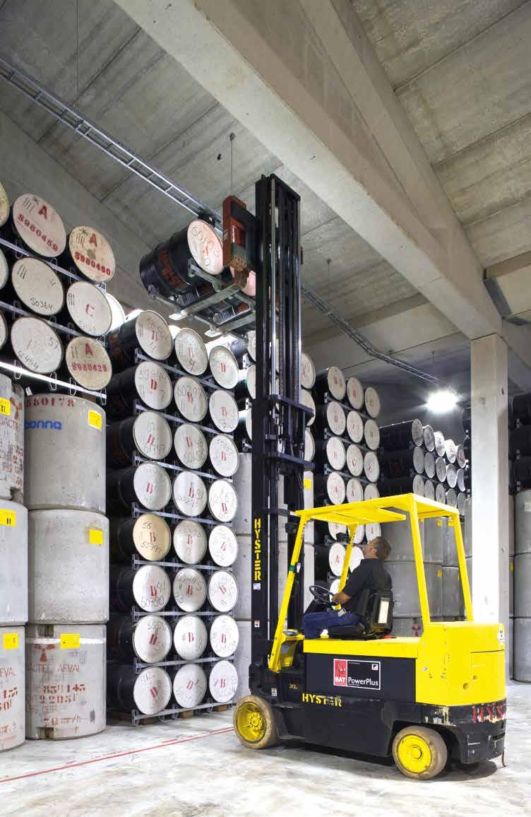
74
SUMMARY OPERA SAFETY CASE. Date: 20 December 2017 Compilers: Ewoud Verhoef, Erika Neeft, Neil Chapman, Charles McCombie.
 UMMARY OPERA AFETY AE ate: 20 ecember 2017 ompilers: Ewoud Verhoef, Erika Neeft, Neil hapman, harles Mcombie www.covra.nl ummary What s new in OPERA? The principal objective of this report is to present
UNDERSTANDING THERMAL CONSTRAINTS FOR HIGH-HEAT-GENERATING WASTES IN THE UK. Ann McCall, Martin Cairns
 UNDERSTANDING THERMAL CONSTRAINTS FOR HIGH-HEAT-GENERATING WASTES IN THE UK Ann McCall, Martin Cairns Radioactive Waste Management Limited, Building B587, Curie Avenue, Harwell Oxford, Didcot Oxfordshire,
Retrievability in the BAMBUS-II Project. J.B. Grupa. NRG, the Netherlands
 Retrievability in the BAMBUS-II Project J.B. Grupa NRG, the Netherlands Summary In the context of radioactive waste disposal retrievability can be defined as the capability of waste package retrieval afforded
gas production, consumption and transport in deep geological repositories
 gas production, consumption and transport in deep geological repositories 2 Considering gas in the safety demonstration ENSI requires Nagra to demonstrate the longterm safety of a deep geological repository
Executive Summary performance assessment
 Executive Summary In the United States, low-level radioactive waste is defined as any radioactive waste arising from operations of the nuclear fuel cycle that is not classified as high-level waste (including
Storage and disposal of radioactive waste in Italy
 8 th edition of the International Summer School on Nuclear Decommissioning and Waste Management Storage and disposal of radioactive waste in Italy ANGELO PARATORE Sogin Deputy Director TRINO 15 th September
IAEA-TECDOC-1372 Safety indicators for the safety assessment of radioactive waste disposal
 IAEA-TECDOC-1372 Safety indicators for the safety assessment of radioactive waste disposal Sixth report of the Working Group on Principles and Criteria for Radioactive Waste Disposal September 2003 The
Swedish Radiation Safety Authority Regulatory Code
 Swedish Radiation Safety Authority Regulatory Code ISSN 2000-0987 SSMFS 2008:37 The Swedish Radiation Safety Authority s Regulations and General Advice Concerning the Protection of Human Health and the
Andra s Safety Options of French underground facility Cigéo- a milestone towards the licensing application
 Andra s Safety Options of French underground facility Cigéo- a milestone towards the licensing application S. Voinis, M. Rabardy, L. Griffault From 1991 towards the licensing application- successive safety
Quantitative vs. Qualitative Performance Assessment of Closure
 Quantitative vs. Qualitative Performance Assessment of Closure Heini Reijonen 1, Pirjo Hellä 1, Nuria Marcos 1, Barbara Pastina 2 1 Saanio & Riekkola Oy, Finland 2 Posiva Oy, Finland Safety functions set
WM 07 Conference, February 25 March 1, 2007, Tucson, AZ
 Scenario for the Safety Assessment of Near Surface Radioactive Waste Disposal in Serpong, Indonesia A.S. Purnomo Radioactive Waste Technology Center, National Nuclear Energy Agency (PTLR - BATAN), Puspiptek,
ESV EURIDICE GIE. European Underground Research Infrastructure for Disposal of nuclear waste in Clay Environment
 1 ESV EURIDICE GIE European Underground Research Infrastructure for Disposal of nuclear waste in Clay Environment 2 Different types of waste Heat! 4 Volume of radioactive waste based on 40 years of exploitation
B. Cahen, S. Voinis Andra, France. A step by step process within Iterative loops from feasibility to license
 FROM THE FEASIBILITY ASSESSMENT TO THE LICENSING: APPLICATION ORGANISATION OF THE SAFETY CASE INTERACTIVE DEVELOPMENT OF ENGINEERING/PA/KNOWLEDGE MANAGEMENT, KEY ISSUES ADDRESSED BY GEOSCIENCE B. Cahen,
WM2012 Conference, February 26 March 1, 2012, Phoenix, Arizona, USA
 A Prototype Performance Assessment Model for Generic Deep Borehole Repository for High-Level Nuclear Waste 12132 Joon H. Lee, Bill W. Arnold, Peter N. Swift, Teklu Hadgu, Geoff Freeze, and Yifeng Wang
Use of natural analogues in the Finnish safety case status update on Complementary Considerations
 Use of natural analogues in the Finnish safety case status update on Complementary Considerations Heini Reijonen, Geological Survey of Finland, Espoo, Finland, heini.reijonen@gtk.fi Marja Vuorio, Posiva
IAEA CLASSIFICATION OF RADIOACTIVE WASTE
 IAEA CLASSIFICATION OF RADIOACTIVE WASTE GERARD BRUNO Workshop on Clearance of Decommissioning Waste 6 9 November 2012, Bangkok, Thailand Outline Overview of radioactive waste arising Waste management
Yucca Mountain. High-level Nuclear Waste Repository
 Yucca Mountain High-level Nuclear Waste Repository The purpose of the Yucca Mountain Site Characterization Project is to determine if Yucca Mountain, Nevada, is a suitable site for a spent nuclear fuel
Criticality Safety in Geological Disposal
 Criticality Safety in Geological Disposal RSC Radiochemistry Group, 2 December 2009, Manchester Presented by Peter Wood, RWMD Contents NDA & Geological Disposal Facility (GDF) Fissile Material Inventory
PE/NRX/15. UNITED KINGDOM NIREX LIMITED Rock Characterisation Facility. PROOF OF EVIDENCE OF Dr A J HOOPER BsC, PhD REPOSITORY PERFORMANCE
 PE/NRX/15 Appellant Ref: DB/CD 8.5.1 LPA Ref: 4/94/9011 DOE Ref: APP/HO900/A/94/247019 UNITED KINGDOM NIREX LIMITED Rock Characterisation Facility Longlands Farm, Gosforth, Cumbria PROOF OF EVIDENCE OF
A S S E S S M E N T R E P O R T
 ASSESSMENT REPORT Generic Design Assessment: Disposability Assessment for Wastes and Spent Fuel arising from Operation of the Westinghouse Advanced Passive Pressurised Water Reactor (AP1000) Part 1: Main
WM2013 Conference, February 24 28, 2013, Phoenix, Arizona, USA. Geological Disposal Concept Selection Aligned with a Voluntarism Process 13538
 Geological Disposal Concept Selection Aligned with a Voluntarism Process 13538 Glenda Crockett and Samantha King Nuclear Decommissioning Authority, Building 587, Curie Avenue, Harwell Oxford, Didcot, Oxfordshire,
Safe disposal of spent nuclear fuel The KBS-3 method. Olle Olsson SKB
 Safe disposal of spent nuclear fuel The KBS-3 method Olle Olsson SKB 1 Why SKB? The nuclear power industry is responsible for taking care of its own waste. The industry has formed SKB to fulfill this task
Long-term safety of disposal of spent nuclear fuel. 1 General 3 2 Radiation safety 3
 GUIDE 23 May 2001 YVL 8.4 Long-term safety of disposal of spent nuclear fuel 1 General 3 2 Radiation safety 3 2.1 General principle 3 2.2 Application of the dose constraints 3 2.3 Application of the activity
H. Geckeis, V. Metz Robustness vs. Flexibility and Monitorability in Nuclear Waste Disposal
 H. Geckeis, V. Metz Robustness vs. Flexibility and Monitorability in Nuclear Waste Disposal Workshop Technological Monitoring and Long-Term Governance, Karlsruhe, 18. + 19.10.2016 KIT Die Forschungsuniversität
ABSTRACT INTRODUCTION. T-11-3, P-3b-172. P. Croüail 1, T. Schneider 1, A. Sugier 2 1 CEPN BP n 48, Fontenay-aux-Roses Cedex France 2
 Evaluation of the Impact and Inter-Generation Risk Transfers Related to the Release and Disposal of Radioactive Waste from the Nuclear Fuel Cycle: A Methodological Exercise P. Croüail 1, T. Schneider 1,
Geological Disposal Through Global Collaboration
 Geological Disposal Through Global Collaboration Nuclear Waste Management Organization of Japan =Geological Disposal November 2016 NUMOʼs mission The safe and reliable disposal of radioactive waste produced
The interface between nuclear safeguards and radioactive waste disposal: Emerging issues
 The interface between nuclear safeguards and radioactive waste disposal: Emerging issues Experts are examining requirements and policies for applying safeguards at geological waste repositories and related
Geological disposal of higher-activity radioactive waste. June 2010
 Geological disposal of higher-activity radioactive waste June 2010 1 Nuclear Decommissioning Authority Delivering the largest environmental clean-up programme in Europe at 19 existing nuclear facilities
INTRODUCTION. Note: The following is based on The Principles of Radioactive Waste Management [1].
![INTRODUCTION. Note: The following is based on The Principles of Radioactive Waste Management [1].](/thumbs/85/92074531.jpg "INTRODUCTION. Note: The following is based on The Principles of Radioactive Waste Management [1].") INTRODUCTION The Principles of Radioactive Waste Management Note: The following is based on The Principles of Radioactive Waste Management [1]. Since the beginning of the twentieth century, research and
INTRODUCTION The Principles of Radioactive Waste Management Note: The following is based on The Principles of Radioactive Waste Management [1]. Since the beginning of the twentieth century, research and
NDA Report no. NDA/RWMD/067. Geological Disposal Generic Waste Package Specification
 NDA Report no. NDA/RWMD/067 Geological Disposal Generic Waste Package Specification March 2012 NDA Report no. NDA/RWMD/067 Geological Disposal Generic Waste Package Specification March 2012 Conditions
Kathryn Higley, PhD, CHP Professor, Assistant Department Head. Oregon State University
 Environmental Transport Kathryn Higley, PhD, CHP Professor, Assistant Department Head Nuclear Engineering & RadiationHealth Physics Oregon State University Purpose To present an overview of mechanisms
U.S. Nuclear Regulatory Commission Standard Review Plan for Activities Related to U.S. Department of Energy Waste Determinations
 U.S. Nuclear Regulatory Commission Standard Review Plan for Activities Related to U.S. Department of Energy Waste Determinations A.H. Bradford, D.W. Esh, A.C. Ridge, A. Ryan Whited U.S. Nuclear Regulatory
Postclosure Assessment Modelling of a Deep Geologic Repository for Low and Intermediate Level Radioactive Waste in Ontario, Canada
 Postclosure Assessment Modelling of a Deep Geologic Repository for Low and Intermediate Level Radioactive Waste in Ontario, Canada - 15145 Russell C Walke*, Richard H Little*, Helen Leung** * Quintessa
Saligny site characterization and community confidence building. Daniela Diaconu RATEN ICN Romania
 Saligny site characterization and community confidence building Daniela Diaconu RATEN ICN Romania Outlines Research activities on waste management Activity on Saligny site characterisation Participation
Status of the Cigéo Project in France
 Status of the Cigéo Project in France French Industrial Geological Disposal Project LUCOEX Conference & Workshop Full Scale Demonstration Tests in Technology Development of Repositories for Disposal of
Technical Report. Overview of Knowledge Coverage for Geological Disposal. Bill Miller. AMEC Report Reference: Client Reference:
 Technical Report Overview of Knowledge Coverage for Geological Disposal Bill Miller AMEC Report Reference: 200094 Client Reference: ONR158 Issue Number: 1.1 Date of Report: 13th January 2015 DOCUMENT ISSUE
Sylvie Voinis 1, Soraya Thabet 1 & Frédéric Plas 1
 CIGÉO PROJECT: DEFINITION AND STATUS OF ANDRA S MONITORING STRATEGY Sylvie Voinis 1, Soraya Thabet 1 & Frédéric Plas 1 1 Andra, France 2 Table of Content 1. Framework What is Cigéo? Key milestones of Cigéo
WASTE ACCEPTANCE REQUIREMENTS FOR THE KONRAD REPOSITORY
 WASTE ACCEPTANCE REQUIREMENTS FOR THE KONRAD REPOSITORY Peter W. Brennecke Bundesamt für Strahlenschutz (BfS) Salzgitter, Germany IAEA - DISPONET Workshop " Waste Acceptance Criteria For Disposal of Very
Complementary considerations in the safety case, support from natural analogues and natural systems
 Complementary considerations in the safety case, support from natural analogues and natural systems Anne Lehtinen 13 th NAWG Workshop, May 13 th -16 th 2013, Nagoya www.posiva.fi/en Outline Introduction
ISSUES ASSOCIATED WITH THE CO-DISPOSAL OF ILW/LLW AND HLW/SF IN THE UNITED KINGDOM
 ISSUES ASSOCIATED WITH THE CO-DISPOSAL OF ILW/LLW AND HLW/SF IN THE UNITED KINGDOM S.J. King and M. Poole UK Nirex Ltd, Curie Avenue, Harwell, Didcot, Oxon, OX11 0RH, UK United Kingdom ABSTRACT Nirex s
An Overview of the Prioritisation Methodology & SRA
 An Overview of the Prioritisation Methodology & SRA Amba Hotel, Marble Arch, London Tuesday 4 th April 2017 Ellie Scourse, MCM, Tara Beattie, MCM, Ray Kowe, RWM, Jon Martin, RWM On peut toujours viser
Implementation and R&D Needs for Storage and Geological Disposal of the UK s s Intermediate and High Level Radioactive Wastes.
 Implementation and R&D Needs for Storage and Geological Disposal of the UK s s Intermediate and High Level Radioactive Wastes. A Personal Materials View. Prof. Bill Lee Department of Materials, Imperial
)) nwmo NUCLEAR WASTE. Adaptive Phased Management. Postclosure Safety Assessment of a Used Fuel Repository in Sedimentary Rock
) nwmo NUCLEAR WASTE. Adaptive Phased Management. Postclosure Safety Assessment of a Used Fuel Repository in Sedimentary Rock") Adaptive Phased Management Postclosure Safety Assessment of a Used Fuel Repository in Sedimentary Rock ---------------)) Pre-Project Report NWMO TR-2013-07 December 2013 Prepared by nwmo NUCLEAR WASTE
Adaptive Phased Management Postclosure Safety Assessment of a Used Fuel Repository in Sedimentary Rock ---------------)) Pre-Project Report NWMO TR-2013-07 December 2013 Prepared by nwmo NUCLEAR WASTE
Initial Plug and Seal Design for the Dutch Repository Concept (PPT)
") Delft University of Technology Initial Plug and Seal Design for the Dutch Repository Concept (PPT) Vardon, Phil; Yuan, Jiao; Hicks, Michael; Li, Yajun Publication date 2016 Citation (APA) Vardon, P., Yuan,
Delft University of Technology Initial Plug and Seal Design for the Dutch Repository Concept (PPT) Vardon, Phil; Yuan, Jiao; Hicks, Michael; Li, Yajun Publication date 2016 Citation (APA) Vardon, P., Yuan,
WM2013 Conference, February 24 28, 2013, Phoenix, Arizona, USA. NRC Monitoring of Salt Waste Disposal at the Savannah River Site 13147
 ABSTRACT NRC Monitoring of Salt Waste Disposal at the Savannah River Site 13147 Karen E. Pinkston, A. Christianne Ridge, George W. Alexander, Cynthia S. Barr, Nishka J. Devaser, and Harry D. Felsher U.S.
RWM TECHNICAL NOTE No ASSESSMENT REPORT
 RWM TECHNICAL NOTE No. 23788023 ASSESSMENT REPORT Generic Design Assessment: Disposability Assessment for Wastes and Spent Fuel arising from Operation of the UK ABWR Part 1: Main Report Document information
Radioactive Waste Disposal. Piero Risoluti
 7th edition of the International Summer School on Nuclear Decommissioning and Waste Management 14-18 September 2015, JRC Ispra (Italy) Radioactive Waste Disposal Options and Practices Piero Risoluti 1
Need for PA in. Site Selection. The road to a final reposito. ory for spent nuclear fuel. Experience. the Swedish. Siting process
 Need for PA in Site Selection the Swedish Experience The road to a final reposito ory for spent nuclear fuel Accumulation of knowledge Siting process Hultsfred Malå Nyköping Oskarshamn Storuman Tierp Älvkarleby
National Inventory of Radioactive Materials and Waste The Essentials
 National Inventory of Radioactive Materials and Waste 2012 The Essentials National Inventory of Radioactive Materials and Waste 2012 ISSUES AND PRINCIPLES OF THE MANAGEMENT OF RADIOACTIVE MATERIALS AND
Geological Disposal of Radioactive Waste
 OFFICIAL Geological Disposal of Radioactive Waste Institute of Physics Nuclear Industry Group, in collaboration with Radioactive Waste Management Ltd (RWM) 13 th July 2016, Birchwood, Warrington *Only
General Groundwater Concepts
 General Groundwater Concepts Hydrologic Cycle All water on the surface of the earth and underground are part of the hydrologic cycle (Figure 1), driven by natural processes that constantly transform water
WM2015 Conference, March 15 19, 2015, Phoenix, Arizona, USA
 Safety Assessment for the Radon-Type Surface Disposal Facility at Saakadze, Georgia 15406 ABSTRACT Bernt Haverkamp *, Heinz Kroeger ** * DBE Technology GmbH ** TÜV NORD EnSys Hannover The Saakadze disposal
WM2012 Conference, February 26 March 1, 2012, Phoenix, Arizona, USA
 A Preliminary Performance Assessment for Salt Disposal of High-Level Nuclear Waste 12173 Joon H. Lee, Daniel Clayton, Carlos Jove-Colon, and Yifeng Wang Sandia National Laboratories, Albuquerque, NM ABSTRACT
LONG-TERM ENVIRONMENTAL IMPACT OF UNDERGROUND DISPOSAL OF P&T WASTE. G. Volckaert, D. Mallants SCK CEN, Boeretang Mol Belgium
 LONG-TERM ENVIRONMENTAL IMPACT OF UNDERGROUND DISPOSAL OF P&T WASTE G. Volckaert, D. Mallants SCK CEN, Boeretang 200 2400 Mol Belgium R. Bush AEA-Technology L. Lambers GRS, Schwertnergasse 1 50667 Köln
International Conference on the Safety of Radioactive Waste Management. Closure Session. Friday, 25 November Vienna, Austria.
 International Conference on the Safety of Radioactive Waste Management Closure Session Friday, 25 November 2016 Vienna, Austria Board Room A (M1) Conclusions from the International Conference on the Safety
Legislation and Technical Aspects of Regulation on Waste Containing Mercury in Germany and Europe
 S1_10 Legislation and Technical Aspects of Regulation on Waste Containing Mercury in Germany and Europe Thomas Brasser, GRS Who is GRS ( Plant & Reactor Safety Ltd. ) Non-profit expert and research organisation
Operational Issues In Radioactive Waste Management and Nuclear Decommissioning. Disposal of Radioactive Waste
 INTERNATIONAL SUMMER SCHOOL 9-13 September 2013 - JRC Ispra (Italy) Operational Issues In Radioactive Waste Management and Nuclear Decommissioning Disposal of Radioactive Waste Piero Risoluti Summer School
The French geological disposal project Cigéo: A converging approach
 The French geological disposal project Cigéo: A converging approach 1,3 10 6 m 3 of radioactive wastes are already produced in France 90% of the volume of radioactive waste produced each year already benefit
REVIEW OF INTERNATIONAL PROGRESS IN TRANSURANIC AND LONG-LIVED INTERMEDIATE LEVEL WASTE DISPOSAL
 ICEM 05: The 10 th International Conference on Environmental Remediation and Radioactive Waste Management September 4-8, 2005, Scottish Exhibition & Conference Centre, Glasgow, Scotland ICEM05-1377 REVIEW
C-40 (May 13) Managing integration of pre-closure activities and post-closure safety in the Safety Case for Geological Disposal
 Managing integration of pre-closure activities and post-closure safety in the Safety Case for Geological Disposal") C-40 (May 13) Managing integration of pre-closure activities and post-closure safety in the Safety Case for Geological Disposal FOREWORD One of the IAEA s statutory objectives is to seek to accelerate
C-40 (May 13) Managing integration of pre-closure activities and post-closure safety in the Safety Case for Geological Disposal FOREWORD One of the IAEA s statutory objectives is to seek to accelerate
IAEA-TECDOC Safety considerations in the disposal of disused sealed radioactive sources in borehole facilities
 IAEA-TECDOC-1368 Safety considerations in the disposal of disused sealed radioactive sources in borehole facilities August 2003 The originating Sections of this publication in the IAEA were: Waste Safety
IAEA Classification on Radioactive Waste
 ANSN RWMTG Regional Workshop on Clearance of Decommissioning Waste Bangkok, Thailand, 18-21 October 2011 Classification on Radioactive Waste Gerard Bruno Radioactive Waste and Spent Fuel Management Unit
IAEA-TECDOC Monitoring of geological repositories for high level radioactive waste
 IAEA-TECDOC-1208 Monitoring of geological repositories for high level radioactive waste April 2001 The originating Section of this publication in the IAEA was: Waste Technology Section International Atomic
DRAFT IMPLEMENTING DECREE. of 2016
 1. ------IND- 2016 0202 CZ- EN- ------ 20160523 --- --- PROJET II. DRAFT IMPLEMENTING DECREE of 2016 on the requirements for the safe management of radioactive waste and on the decommissioning of nuclear
FRENCH WASTE MANAGEMENT STRATEGY FOR A SUSTAINABLE DEVELOPMENT OF NUCLEAR ENERGY
 FRENCH WASTE MANAGEMENT STRATEGY FOR A SUSTAINABLE DEVELOPMENT OF NUCLEAR ENERGY Charles Courtois and Franck Carré Waste Management Research Direction CEA/Saclay, Gif-sur-Yvette, Cedex, France Abstract
FACT FLASH. 5: Groundwater. What is groundwater? How does the ground store water? Fact Flash 5: Groundwater
 FACT FLASH 5: Groundwater What is groundwater? Groundwater is fresh water (from rain or melting ice and snow) that soaks into the soil and is stored in the tiny spaces (pores) between rocks and particles
Guide YVL D.5, Disposal of nuclear waste (13/2/2018)
") 1 (20) Guide YVL D.5, Disposal of nuclear waste (13/2/2018) 1. Scope of application Guide YVL D.5 addresses the extensive disposal of nuclear waste in repositories constructed inside the bedrock. The types
1 (20) Guide YVL D.5, Disposal of nuclear waste (13/2/2018) 1. Scope of application Guide YVL D.5 addresses the extensive disposal of nuclear waste in repositories constructed inside the bedrock. The types
IAEA-TECDOC-482 PREVENTION AND MITIGATION OF GROUNDWATER CONTAMINATION FROM RADIOACTIVE RELEASES
 IAEA-TECDOC-482 PREVENTION AND MITIGATION OF GROUNDWATER CONTAMINATION FROM RADIOACTIVE RELEASES A TECHNICAL DOCUMENT ISSUED BY THE INTERNATIONAL ATOMIC ENERGY AGENCY, VIENNA, 1988 PREVENTION AND MITIGATION
Backfilling and Sealing Materials. Horst-Jürgen Herbert, GRS 30 th November, 2010
 Backfilling and Sealing Materials Horst-Jürgen Herbert, GRS 30 th November, 2010 Content Introduction Functions of backfill and sealing materials EBS concepts for different waste types Salt and cement
Postclosure Safety Assessment (V1): Analysis of Human Intrusion and Other Disruptive Scenarios
: Analysis of Human Intrusion and Other Disruptive Scenarios") Postclosure Safety Assessment (V1): Analysis of Human Intrusion and Other Disruptive Scenarios July 2009 Prepared by: J Penfold and R Little NWMO DGR-TR-2009-03 Note: The Nuclear Waste Management Organization
Postclosure Safety Assessment (V1): Analysis of Human Intrusion and Other Disruptive Scenarios July 2009 Prepared by: J Penfold and R Little NWMO DGR-TR-2009-03 Note: The Nuclear Waste Management Organization
Regulatory Challenges in the Licensing of a Spent Nuclear Fuel Repository in Sweden 14483
 Regulatory Challenges in the Licensing of a Spent Nuclear Fuel Repository in Sweden 14483 Johan Anderberg Swedish Radiation Safety Authority (SSM), Stockholm, Sweden ABSTRACT Since March 2011, the Swedish
EXTERNAL REPORT. ONDRAF/NIRAS contract CCHO /00/00. SCK CEN Boeretang 200 BE-2400 Mol Belgium. Eef Weetjens. February, 2009 IPA-PAS
 EXTERNAL REPORT SCK CEN-ER-86 09/EWe/P-20 Update of the near field temperature evolution calculations for disposal of UNE-55, MOX-50 and vitrified HLW in a supercontainer- based geological repository Eef
NDA Technical Note no
 NDA Technical Note no. 11339711 Geological Disposal Generic Design Assessment: Summary of Disposability Assessment for Wastes and Spent Fuel arising from Operation of the Westinghouse AP1000 October 2009
THE ÄSPÖ HARD ROCK LABORATORY
 THE ÄSPÖ HARD ROCK LABORATORY A dress rehearsal for the construction of a final repository for spent nuclear fuel is currently being held deep down in the Swedish bedrock in the Äspö Hard Rock Laboratory
RECENT PROGRESS OF THE HLW DISPOSAL PROGRAM IN JAPAN
 RECENT PROGRESS OF THE HLW DISPOSAL PROGRAM IN JAPAN Ê Toshiaki Ohe Department of Nuclear Engineering, Tokai University, 1117 Kita Kaname, Hiratsuka, Kanagawa 259-1292, Japan ohe@keyaki.cc.u-tokai.ac.jp
Issues of the High-Level Radioactive Waste in Japan
 Issues of the High-Level Radioactive Waste in Japan Prof. Dr. Kenji YAMAJI Director-General, Research Institute of Innovative Technology for the Earth (RITE) International Symposium on Nuclear Back-end
Government Decree (736/2008) on the safety of disposal of nuclear waste
 on the safety of disposal of nuclear waste") Government Decree (736/2008) on the safety of disposal of nuclear waste Issued in Helsinki 27 November 2008 According to the Government decision made on the submission by the Ministry of Employment and
Government Decree (736/2008) on the safety of disposal of nuclear waste Issued in Helsinki 27 November 2008 According to the Government decision made on the submission by the Ministry of Employment and
The Meuse/Haute Marne Centre : Underground Research Laboratory Technological Exhibition Facility
 The Meuse/Haute Marne Centre : Underground Research Laboratory Technological Exhibition Facility Marielle Girard Public relations officer AGENCE NATIONALE POUR LA GESTION DES DÉCHETS RADIOACTIFS A new
NKS Seminar on Decommissioning of Nuclear Facilities, September 14-16, 2010
 NKS Seminar on Decommissioning of Nuclear Facilities, September 14-16, 2010 Behaviour of Carbon-14 Released from Activated Steel in Repository Conditions a Key Issue in the Long-term Safety of Decommissioning
Performance assessment and the safety case: Lessons from recent international projects and areas for further development
 Performance assessment and the safety case: Lessons from recent international projects and areas for further development Daniel A. Galson Galson Sciences Limited United Kingdom Lucy Bailey Nuclear Decommissioning
Assessment of the long-term safety of repositories
 Gesellschaft für Anlagenund Reaktorsicherheit (GRS) mbh Assessment of the long-term safety of repositories Scientific basis GRS - 237 Gesellschaft für Anlagenund Reaktorsicherheit (GRS) mbh Assessment
Understanding the Evolution of the Repository and the Olkiluoto Site. Kari Koskinen (Posiva Oy) Barbara Pastina (Saanio & Riekkola Oy)
 Barbara Pastina (Saanio & Riekkola Oy)") Understanding the Evolution of the Repository and the Olkiluoto Site Kari Koskinen (Posiva Oy) Barbara Pastina (Saanio & Riekkola Oy) Steps in assessing safety 1. Description of the site and processes
Understanding the Evolution of the Repository and the Olkiluoto Site Kari Koskinen (Posiva Oy) Barbara Pastina (Saanio & Riekkola Oy) Steps in assessing safety 1. Description of the site and processes
Radioactive Waste and Spent Fuel Management activities in the IAEA
 Radioactive Waste and Spent Fuel Management activities in the Gérard Bruno Radioactive Waste and Spent Fuel Management Unit Department of Nuclear Safety and Security International Atomic Energy Agency
tens-of-thousands to about 300,000 years; and Np-237 and Pu-242 were dominant in the period from 300,000 to one million years.
 tens-of-thousands to about 300,000 years; and Np-237 and Pu-242 were dominant in the period from 300,000 to one million years. 7.3.2.3 Key Features of the TSPA-VA Base Case Models This section summarizes
NDA Report no. NDA/RWM/146. Geological Disposal. Review of Alternative Radioactive Waste Management Options. March 2017
 NDA Report no. NDA/RWM/146 Geological Disposal Review of Alternative Radioactive Waste Management Options March 2017 NDA Report no. NDA/RWM/146 Geological Disposal Review of Alternative Radioactive Waste
IAEA-TECDOC Technical considerations in the design of near surface disposal facilities for radioactive waste
 IAEA-TECDOC-1256 Technical considerations in the design of near surface disposal facilities for radioactive waste November 2001 The originating Section of this publication in the IAEA was: Waste Technology
Thermal evolution of the repository the effect of heat generating waste
 Report R-18-04 November 2018 Thermal evolution of the repository the effect of heat generating waste Report for the safety evaluation SE-SFL SVENSK KÄRNBRÄNSLEHANTERING AB SWEDISH NUCLEAR FUEL AND WASTE
Safety functions, performance targets and technical design requirements for a KBS-3V repository
 Posiva SKB Report 01 January 2017 Safety functions, performance targets and technical design requirements for a KBS-3V repository Conclusions and recommendations from a joint SKB and Posiva working group
Joint ICTP-IAEA School of Nuclear Energy Management August 2011
 2257-41 Joint ICTP-IAEA School of Nuclear Energy Management 8-26 August 2011 National Policy & Strategy for Spent Fuel and Radioactive Waste Management Paul Degnan IAEA, Vienna Austria POLICIES AND STRATEGIES
How Spent Fuel Management Affects Geologic Disposal
 ?? Vitrified Waste?? Geologic Repository Spent Nuclear Fuel Stored or Processed Fuel How Spent Fuel Management Affects Geologic Disposal Peter Swift Senior Scientist Sandia National Laboratories, USA International
Organizing and Structuring the OPERA Research Efforts using Safety Statements
 Organizing and Structuring the OPERA Research Efforts using Safety Statements OPERA-PU-NRG2112 Radioactive substances and ionizing radiation are used in medicine, industry, agriculture, research, education
Document Number: NWMO TR Revision: 000 Class: Public Page: 1
 Document Number: NWMO TR-2013-07 Revision: 000 Class: Public Page: 1 1. INTRODUCTION 1.1 Purpose and Scope The purpose of this report is to present a case study that illustrates the Nuclear Waste Management
On-Site, Near Surface Disposal of Graphite Wastes in the UK
 On-Site, Near Surface Disposal of Graphite Wastes in the UK - 11271 Adam Meehan*, Peter Sibley*, Al Johnson*, Jeremy Lightfoot**, Duncan Jackson*** * EnergySolutions EU Ltd, First Floor, Stella Building,
WATER AND THE HYDROLOGIC CYCLE
 WATER AND THE HYDROLOGIC CYCLE Summary Water is essential for the support of life and can be considered as a fundamental environmental good. Water is needed to support human habitation, grow crops and
Geological Disposal Generic Design Assessment: Summary of Disposability Assessment for Wastes and Spent Fuel arising from Operation of the UK EPR
 NDA Technical Note no. 11261814 Geological Disposal Generic Design Assessment: Summary of Disposability Assessment for Wastes and Spent Fuel arising from Operation of the UK EPR October 2009 NDA Technical
Implementation of the Borehole Disposal Concept in Ghana-Status
 Implementation of the Borehole Disposal Concept in Ghana-Status E.T. Glover National Radioactive Waste Management Centre National Nuclear Research Institute Ghana Atomic Energy Commission Ghana Content
Andra s Responses to the Public Debate on the Cigeo Geological Repository Project
 Andra s Responses to the Public Debate on the Cigeo Geological Repository Project In accordance with Articles L.121-13 and R.121-11 of the Environmental Code, the Board of Administrators of Andra met May
Used Nuclear Fuel Management Options
 Used Nuclear Fuel Management Options Main challenges and AREVA overall positioning November 15, 2016 Isabelle Morlaes, AREVA, Sales Back-End Dpt. SVP France & New Business Development AREVA Proprietary
Implementing Geological Disposal
 Implementing Geological Disposal A Framework for the long-term management of higher activity radioactive waste July 2014 Crown copyright 2014 URN 14D/235 You may re-use this information (not including
Thank you for the opportunity to comment on the Draft EIS for the Nuclear Power Demonstration Closure Project.
 Date: January 2, 2017 From: J. R. Walker To: Lucia Abellan, Environmental Assessment Officer Canadian Nuclear Safety Commission By email: cnsc.ea-ee.ccsn@canada.ca Subject line: ATTN: Lucia Abellan - Comments