FAYOUM CITY SEWAGE TREATMENT PLANT, DEVELOPMENT STAGES, CASE STUDY
|
|
|
- Kelly Nicholson
- 6 years ago
- Views:
Transcription
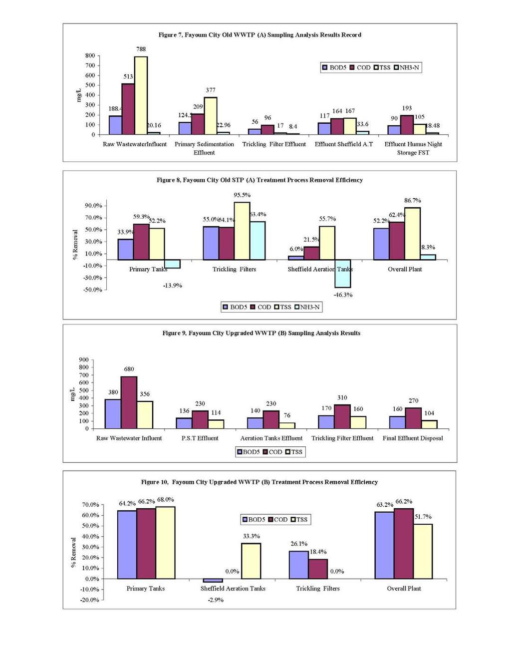
1 FAYOUM CITY SEWAGE TREATMENT PLANT, DEVELOPMENT STAGES, CASE STUDY Ahmed El-Zayat, Environmental Engineering Group, Egypt l: Introduction This case study focuses on three development stages of different types of processes utilized by the Fayoum city wastewater treatment plant in Egypt, in activated sludge biological wastewater treatment applications, namely: trickling filters, Sheffield aeration, and conventional processes. The three development stages have been evaluated, showing the design features, basis, parameters, and capacity. The performance analysis of each case is evaluated based on the experimental work and sampling analysis records for the influent characteristics and effluent quality. The assessment of each development process type is identified by the final effluent quality disposal to the drain with respect to the legal protection Law 48/82 and regulations of Egypt. FAYOUM CITY WASTEWATER TREATMENT PLANT DEVELOPMENT STAGES Fayoum City Old Wastewater Treatment Plant (A), 1936 The British established the Fayoum city old Wastewater treatment plant in The design flow was 200 l/s. The plant was located in the Kohafa area, 2.20 km east of the southeast edge of the city. The final effluent traveled 0.75 km east to be finally disposed of at the Al Bates Drain (Main Agriculture Drain in Fayoum). The effluent traveled from the Al Bates drain northwards and then west about 50 km where it entered the upper eastern end of Lake Quarun. Fayoum City Upgraded Wastewater Treatment Plant (B), 1986 In 1986 the plant was upgraded and rehabilitated, in order to improve the plant flow design capacity and its efficiency. The upgrading works were completed by extending vertically (increase the flow capacity) from 200 to 300 l/s (1,080 m 3 /hr). Fayoum City New Wastewater Treatment Plant (C), 1996 In order to increase the wastewater flow discharge of Fayoum city up to 70,000 m 3 /day in 1996, and to mitigate environmental violations caused by the upgraded plant (B) effluent; a new plant was established by NOPAWSD. The construction of the new plant sought to meet the environmental regulations and capacity requirements for Fayoum city via horizontal extension of the plant design, reaching a total capacity 40,000 m 3 /day. This was implemented in two stages, with a flow capacity of 20,000 m 3 /day reached each day and then extended during the design extension, to reach a total flow 60,000 m 3 /day in the year FINAL EFFLUENT QUALITY AND PERFORMANCE EFFICIENCY Fayoum City Upgraded Old Plant (B) Performance Efficiency The plant was upgraded to become a high-rate trickling filter plant, with a capacity of 300 l/s. While treatment efficiency of the trickling filters could be expected to decline somewhat under such higher hydraulic and corresponding organic loads, the overall treatment efficiency of the STP and its effluent quality should be better than those found in the results of sampling analysis. The final STP effluent quality (F-E) and treatment efficiency represent a combination of (F-P), (F-AS), and (F-TF). The STP effluent (F-E) 189
2 BOD 5 was 160mg/l, representing an overall treatment efficiency of 66.2 percent or an intermediate between primary and secondary treatment. Suspended solids concentration in the effluent was comparatively high at 104 mg/l due to the high influent suspended solids and the high percentage of primary effluent by-passed to the night tank. However, the percent removal of suspended solids at 51.7 percent proved disappointing, as it was significantly lower than the 85 percent removal of suspended solids from secondary treatment of because the final clarifiers were not constructed. Fayoum City New STP (C) Performance Efficiency The final effluent quality of plant (C) is yielding impressive results; as they are comply with standard limits of Law 48/1982. The implementation of a conventional single-stage activated sludge process in the new wastewater treatment plant was successful and has no negative impacts on the environment, when taking into consideration that the plant capacity is running at a capacity of 695 l/s. CONCLUSION The different development stages of the Fayoum City Wastewater treatment plant are as follows: (A) Old Plant, (B) Upgraded Plant, and (C) New Plant, each showing plant performance and unit treatment process efficiency for the different process trains. The effluent quality impact of the Fayoum City Old Upgraded Plant is not in compliance with the standards limits of the Ministry of Irrigation and Water Resources under Law No. 48/1982 due to lack of final settling tanks and the other operational problems. The final effluent quality of the Fayoum City New Plant (C) is giving impressive results, which in compliance with the standard limits of the Ministry of Irrigation and Water Resources Law No. 48/1982. The implementation of a conventional single-activated sludge biological treatment process has no significant impacts on agricultural drains, water bodies and other aspects of the surrounding environment. It will be obvious that the activated sludge process, when compared to plants employing biological filter beds, provides a method of treatment which is capable of effecting considerable economic gains. It must be stressed that all claims and comparisons are substantiated by results obtained under actual plant working conditions over a period of years, as the method and the equipment have already proved successful in a variety of applications. The major advantages of an activated sludge treatment plant are therefore self-evident in a variety of ways: o In economic terms, by reducing the total ground area requirement. o In practical terms, by simplifying construction and management through the use of vertical-shaft aerators which can be used in deeper channel and present a more compact arrangement. o In terms of quality, the activated sludge system readily achieves a 20:20 BOD/SS, standard. CASE STUDY: FAYOUM CITY WASTEWATER TREATMENT PLANT DEVELOPMENT STAGES Fayoum City Old Wastewater Treatment Plant (A), 1936 The British established the Fayoum city old Wastewater treatment plant, in It is located at Kohafa area, approximately 2 km east of the southeast edge of the Fayoum city. The final effluent, after traveling approximately 0.5 km east, enters the Al Bates Drain (main agriculture drain in Fayoum). From this point of entry, the effluent travels north from the Al Bates Drain and then west, for a total of about 50 km, where it enters the upper eastern end of the Lake Quarun (see Figure 1). 190
3 Figure 1: Fayoum City Wastewater Treatment Plant Location Plan N TO CAIRO LAKE QUARUN TO FAYOUM EL BATS DRAIN FAYOUM JOSEPH CHANNEL TO BENI SUEF WTP WWTP Description of unit processes The plant was designed for capacity 200 l/s (17,280 m 3 /d), with the intention to serve until The biological process contains two types of treatment streams: one stream is a trickling filter, and the other stream is working as an activated sludge process or oxidation ditches (Sheffield aeration tanks). The process flow diagram and plan view layout are shown in Figures 2 and 3 below. 191
4 Preliminary and primary treatment units The Inlet chamber receives the influent from the force mains where the manual screens are located. It is then distributed into three grit chambers and collected in the outlet channel before being finally distributed to three primary sedimentation tanks (Lybzeying type). Biological treatment units The biological treatment units are divided into two streams. The first stream flows to the trickling filters followed by the night storage tank (it was used for water storage in the night hours to irrigate the surrounding agriculture land in the mooring hours according to original design, but now is drained to Al-Bates drain). The second stream flows to the aeration tanks (Sheffield type) followed by final sedimentation zones (Dortomond type). The activated sludge is returned by sludge pumps to the inlet of the aeration tank to be mixed with the raw wastewater. Sludge drying beds The primary sludge is received from the primary sedimentation tanks, scum, floating matter, whereas secondary waste/ surplus sludge is received from final sedimentation zones. 192
5 Figure 3: Old Wastewater Treatment Plant Layout? 600 GRP VALVE CHAMBER? 600 SH PST? 600 GRP RAS P/S WAS RAW SEWAGE SLUDGE RAS TREATED EFFLUENT FIGURE 3, OLD FAYOUM WWTP (A) PLAN LAYOUT FAYOUM CITY UPGRADED OLD WASTEWATER TREATMENT PLANT (B), 1986 In 1986 the Fayoum city old wastewater treatment plant was upgraded and rehabilitated in order to improve the plant capacity and efficiency. The upgrading work was done vertically (increasing the flow capacity) from 200 up to 300 l/s (25,920 m 3 /day). This process is explained in more detail in the following sections. Upgrading and modification works Primary Treatment Units a. Inlet Chamber Construction of a new inlet chamber with new screens to sustain a maximum design flow capacity of 500 l/sec. The new inlet chamber was connected to the old inlet chamber via a channel. b. Measuring Discharge Weir Construction of a new measuring weir at the old inlet chamber. c. Grit Chamber Construction of new splitter baffles for equal flow distribution to the three grit chambers with installation of new penstocks for flow control. d. Primary Sedimentation Tanks Lybzeying Adapting primary sedimentation tanks outlet weir to sustain a maximum flow 500 l/s. Biological / Secondary Treatment Units a. Biological Trickling Gravel Filters Upgrading the standard-rate system to a high-rate system by recirculation of final sedimentation zones effluent to inlet of the trickling filters (for dilution of the inlet organic load concentration) and replacing the filter gravel media and the feeding inlet pipes. b. Recirculated Wastewater Pumps for the High-Rate Trickling Filters 193
6 Recirculation of the final sedimentation zones effluent to the biological gravel trickling filters by installing two new pumps (Q= 150 l/sec, H m = 10 m). c. Trickling Filters Effluent Channel Elevation of effluent channel sides to divert the trickling filters effluent from the night storage tank and installation of a new 16 inch pipe which is connected to the recirculation sump. d. Sheffield Aeration Tanks followed by Final Sedimentation Zones "Dortomond" Rehabilitation of the influent distribution weir, replacement of the return activated sludge pumps with new pumps, and rehabilitation of the final sedimentation zones "Dortomond". e. Implementation of the Final Clarifiers The construction of the new final clarifiers was not implemented due to a lack of the construction project budget, which is still affecting the plant s effluent quality. Disinfection works Installation of a new disinfecting chlorinating system, featuring a rectangular contact tank, with outlet discharge measuring weir. Post-aeration by cascade Construction of a new cascade for post-aeration of the final effluent before chlorination, the cascade is 9 m high and consists of three steps, each three meters high and 20 meters wide. Sludge treatment a. Thickeners Construction of new circular tanks 10m in diameter and 4.2m deep for sludge thickening and construction of a new sump to collect primary sludge. b. Drying Sludge Beds Construction of 105 new drying beds, with an under-drain system with submersible pumps. Removal of the existing earth beds by construction of new concrete bottom beds. FAYOUM CITY NEW WASTEWATER TREATMENT PLANT (C), 1996 Due to the increment in the wastewater flow discharge of the Fayoum city (70,000 m 3 /day) and due to the environmental violation from the upgraded plant (B) effluent quality, a new plant was established in The aim was to satisfy the environmental and capacity requirements for Fayoum city as by horizontally extending the plant to a total design capacity of 40,000 m 3 /day. This was implemented in two stages, each stage comprising a 20,000 m 3 /day capacity, and was eventually extended to a maximum flow capacity of 60,000 m 3 /day in the year Description of unit processes The process flow diagram and plan-view layout are shown in Figures 4 and 5 (below). Preliminary Treatment Units a. Deceleration Chamber Reinforced concrete chamber 5.50 m depth. b. Inlet Deceleration Chamber The chamber receives the influent, returned sludge, thickeners supernatant, and drained water from the drying beds. c. Mechanical Screens Four mechanical screens 1.5 m wide with self-cleansing operation every 15 minutes. 194
7 d. Oil, Grease and Grit Removal Chambers Pre-aeration occurs in the grit chambers by air injection via nozzles at 2m deep for oil and grease flotation which will be skimmed. Primary treatment units a. Main Primary Splitter A circular chamber receives the effluent from the grit chambers for distribution into three streams, each with a 20,000 m 3 /day capacity, to three sub-primary splitters. The main primary splitter contains a by-pass line to the Al-Bates drain in case of emergencies. b. Sub-Primary Splitter Three circular tanks each receive effluent from the main primary splitter, which is then distributed into two primary sedimentation tanks. c. Primary Sedimentation Tanks For each stream, two circular tanks receive the effluent from the primary sub-splitter, each with a one hour detention time. The excess or waste sludge from the final sedimentation tank is returned from the WAS pumping station into the sub-splitter to enhance the flocculation process in the primary sedimentation tanks. Secondary biological treatment a. Surface Aeration Tanks Simplex The primary sedimentation tanks effluent is collected in a channel, and then flows to the aeration tanks which includes surface aerators fixed with a vortex stopper (X-shape) at bottom of each aeration tank. The Return Activated Sludge from the final clarifiers is lifted by screw pumps to be mixed with primary sedimentation tanks effluent (MLSS 4000 ppm, aeration detention time is 6 hrs). b. Final Effluent Splitter A circular tank for splitting the aeration tanks effluent into four final sedimentation tanks. c. Final Sedimentation tanks Four circular tanks for each stream (detention time is two hours). Using a scraper, the secondary sludge is collected in a sludge hopper and then drawoff goes into the RAS screw pumps sump. Disinfecting tanks Two rectangular tanks receive the effluent from final clarifiers for disinfection (contact time is 30 minutes with a chlorine dose 15 ppm). Sludge treatment units a. Thickeners Two circular tanks receive excess sludge from the main sludge sump. The sludge is thickened and supernatant is flow out. b. Drying Beds The thickened sludge flows to the drying beds every 12 hours and the drained water flows to a drainage sump to be lifted to the inlet chamber. RAS Screw Lifting and WAS pumping Station It receives RAS from the final clarifiers and is lifted via two screw pumps to the aeration tanks according to the required MLSS ratio (4 g/l). Waste sludge is pumped by two submersible pumps to the main primary splitter for co-settling with the primary sludge. 195
8 ? 300?700 Main Sludge Sump It receives the scum and primary sludge from primary sedimentation tanks. The scum is collected in the main scum sump and pumped via submersible pumps to the thickeners. Main Scum Sump When industrial waste is intruded with the raw wastewater, the scum is not pumped to the main sludge sump, but will be treated separately. Supernatant Pumping Station It receives supernatant from the thickeners, and the drained water from the drying beds is then pumped to the inlet chamber. INLET CHANNEL TO CHLORINATON PLANT?900? 700 A.T.x(4x16x16) GRIT CHAMBER? 400 RAS P/S RAS? 800 WASHOUT WASHOUT VALVE CHAMBER MECHANICAL SCREEN TO OLD STP RAS P/S RAS? 800? 700? 600 GRP INLET CHAMBER? 700? 700? 600 SH? 700 A.T.x(4x16x16) RAW SEWAGE SLUDGE TREATED EFFLUENT FIGURE FROM SUPERNATANT PUMPING STATION? 400 m PST?24 WAS TO THICKENER FST? 30m 5, NEW FAYOUM WWTP (C) PLAN LAYOUT 196
9 EXPERIMENTAL WORKS Fayoum Old WWTP (A) Performance Evaluations The sampling stations and flow points are shown in Figure 6 below. Records of sampling analysis results are obtained from the plant history and are presented in Figure 7 below. The flow measured was 330 l/s. The process treatment percentage removal efficiency is presented in Figure 8. The Fayoum Old WWTP was more than a primary treatment plant in that it contains several secondary unit treatment processes including a dual activated sludge or oxidation ditch unit as well as four large, single-stage, standard-rate trickling filters. However, it lacks final clarifiers and chlorination facilities. Therefore, the plant was capable only of providing treatment intermediate between primary and secondary at that time. Fayoum City Upgraded Old WWTP (B) Performance Evaluation The flow measured was 330 l/s and experimental work done in order to evaluate the implemented modifications (upgrading) works for the Fayoum Upgraded WWTP (B) as presented in figures 9 and 10. The plant was upgraded for a capacity 300 l/s as a high-rate trickling filter plant. Therefore, it appears that it should possible to pass all the flow up to 300 l/s through the trickling filters. While treatment efficiency of the trickling filters can be expected to decline somewhat under such higher hydraulic and corresponding organic loads, the overall treatment efficiency of the STP and its effluent quality should be better than those found in the results of sampling analysis. The final STP effluent quality (F-E) and treatment efficiency represent a combination of (F-P), (F-AS), and (F-TF). The STP effluent (F-E) BOD 5 was 160 mg/l, representing an overall treatment efficiency of 66.2 percent, or constituting an intermediate between primary and secondary treatment. Suspended solids concentration in the effluent was comparatively high at 104 mg/l due to the high influent suspended solids and the high percentage of primary effluent by-passed to the night tank. However, the percent removal of suspended solids was disappointing at 51.7 percent, a figure much lower than secondary treatment of 85 percent, because the final clarifiers were not implemented. Fayoum City New WWTP (C) Performance Evaluation The flow measured was 685 l/s and the results of average yearly sampling experimental work were done in order to evaluate the Fayoum New WWTP (C), as presented in Figures 11 and 12. The final effluent quality of the Fayoum City New Plant (C) yielded impressive results, in compliance with the standards limits of the Ministry of Irrigation and Water Resources under Law No. 48/1982. Fayoum City Wastewater Effluent Quality Impact Assessment The water quality impact analysis of the wastewater flow from the Fayoum Upgraded WWTP (B) and New WWTP (C) on the receiving water bodies, Al Bates Main Agricultural Drain and, in turn on Lake Quarun was performed under the actual treatment levels. These data, in turn, were compared with the standard limits of the Ministry of Irrigation under Public Law 48, as shown Figures 13 and 14 below. 197
10 W W T P INFLUENT SHEFFIELD SYSTEM F-I INFLUENT BOX GRIT CHAMBERS PRIMARY CLARIFIERS F-P F-AS 1 4 ELEVATED CHANNEL TRICKLING FILTERS 2 F-TF 3 F-PB NIGHT TANK (EFFLUENT CHAMBER) F-E W W T P EFFLUENT EFFLUENT DITCH SAMPLING STATION CASCADE FLOW MEASURING F-AD1 F-ED F-AD2 FIGURE 6, FAYOUM OLD WWTP (A) STATIONS & FLOW POINTS 198
11 199
12 200
13 Table (1) Summary of the Fayoum City WWTP Development Stages # ITEM FAYOUM WWTP 1. Old System 1.1 Commissioning Year Type of System Trickling Filter + Sheffield Aeration Tanks 1.3 Type of Process Attached Growth + Suspended Growth, Complete Mix Conventional Activated Sludge 1.4 Process Train Sc + GRC + PST + TF + HNT + SAT + FST 1.5 A.D.F, m 3 /day 17, Upgraded System 2.1 Upgrading Year Type of System Trickling Filter + Sheffield Aeration Tanks 2.3 Type of Process Attached Growth + Suspended Growth, Complete Mix Conventional Activated Sludge 2.4 Process Train Sc + GRC + PST + TF + HNT + SAT + FST 2.5 Type Of Upgrading Vertical Upgrading 2.6 ADF, m 3 /day 25, New Developed System 3.1 Development Year Type of System Conventional Aeration Tank 3.3 Type of Process Suspended Growth, Complete Mix Conventional Activated Sludge 3.4 Process Train Sc + GRC + PST + AT + FST + CT 3.5 Type of Upgrading Horizontal Extension 3.6 ADF, m 3 /day 60, Aeration Tanks Detention Time, hrs 6 4. New Plant (C) Raw Influent Characteristics / Secondary Effluent Quality (% Removal) 4.1 BOD 5, mg/l 485 / 17.8 (96.33%) 4.2 TSS, mg/l 395 / 25 (94%) 4.3 COD, mg/l 790 / 27.3 (97%) 4.4 DO 0.2 / ph 7 / Average Temp. O C Final Effluent Disposal Outfall Al Bates Agricultural Drain Discharge to Lake Quarun 6. Sludge Disposal Drying Beds 7. Surrounding Environment Agricultural Areas Sc (Screens), GRC (Grit Removal Chamber), PST (Primary Sedimentation Tanks), TF (Trickling Filters), HNT (Humus Night Tank), SAT (Sheffield Aeration Tanks), FST (Final Settling Tanks), CT (Contact Tank). CONCLUSION The different development stages of the Fayoum City Wastewater treatment plants are summarized in Table 1: (A) Old Plant, (B) Upgraded Plant, and (C) New Plant, showing the performance and unit treatment process for different process trains. The effluent quality impact of the Fayoum City Upgraded Old Plant is not in compliance with the standard limits of the Ministry of Irrigation and Water Resources under Law No. 48/1982, due to the lack of final settling tanks and the other operational problems. The final effluent quality of the Fayoum City New Plant (C) has yielded impressive results, which comply with the standard limits of the Ministry of Irrigation and Water Resources under Law No. 48/1982. The implementation of a conventional single-stage activated sludge biological treatment process has no significant impacts on the surrounding environment like agricultural drains and water bodies. It will be obvious that the activated sludge process relative to plants employing biological filter beds provides a method of treatment that is capable of achieving considerable economic gains. 201
14 It must be stressed that all claims and comparisons are substantiated by the results obtained under actual plant working conditions over a period of some years. Thus is can be said that the method and the equipment have already proved successful in a variety of applications. The major advantages of an activated sludge treatment plant are self-evident in a number of different ways: o In economic terms, by reducing the total ground area requirement. o In practical terms, construction and management are simpler. The use of vertical-shaft aerators allows operation in a deeper channel and presents a more compact arrangement. o In terms of quality, the activated sludge system readily achieves a 20: 20 BOD/SS, standard. 202
ASH'SHARQIYAH SANDS WATER SUPPLY SCHEME
 ASH'SHARQIYAH SANDS WATER SUPPLY SCHEME Eng. Zaher Bin Khalid Al Sulaimani, Eng. Said Bin Khamis Al Khamisi, Dr. Ali Gharbi, Eng. Ziad Al Aswad; Ministry of Regional Municipalities, Environment & Water
ATTACHMENT 1 GENERAL FACILITY INFORMATION. BOD5 mg/l mg/l TSS mg/l mg/l NH3-N mg/l mg/l
 ATTACHMENT 1 GENERAL FACILITY INFORMATION 1. Facility Name: 2. Type of Facility: 3. Population Served: Present: Design: 4. Flow: Average Maximum Peak 5. Water Quality: Present Design Assumed Actual Source:
INFRASTRUCTURE & OPERATION
 SECTION C: INFRASTRUCTURE & OPERATION Advice on completing this section is provided in the accompanying Guidance Note. C.1 Operational Information Requirements Provide a description of the plant, process
UPGRADING GAZA WASTEWATER TREATMENT PLANT. Gaza City is populated with 550,000 inhabitants and it forms 45% of the Gaza strip population.
 Gaza City Gaza City is populated with 550,000 inhabitants and it forms 45% of the Gaza strip population. Gaza City has the oldest wastewater system in Gaza Strip; it consists of some of 280 kilometers
Wastewater Plant Tour. There Is Gold In Them There Plants
 Wastewater Plant Tour There Is Gold In Them There Plants Why Should I Be Interested In Wastewater Treatment? Every municipality has at least one treatment facility. Many manufactures will have treatment
EVALUATION OF A WATER TREATMENT PLANT PERFORMANCE CASE STUDY
 Seventh International Water Technology Conference IWTC7 Egypt 1-3 April 2003 EVALUATION OF A WATER TREATMENT PLANT PERFORMANCE CASE STUDY M. A. ElDib (1) and Mahmoud A. Azeem Elbayoumy (2) (1) Professor,
WASTEWATER TREATMENT (1)
") Wastewater Engineering (MSc program) WASTEWATER TREATMENT (1) Prepared by Dr.Khaled Zaher Assistant Professor, Public Works Engineering Department, Faculty of Engineering, Cairo University Wastewater Flow
Wastewater Engineering (MSc program) WASTEWATER TREATMENT (1) Prepared by Dr.Khaled Zaher Assistant Professor, Public Works Engineering Department, Faculty of Engineering, Cairo University Wastewater Flow
Sanitary and Environmental Engineering I (4 th Year Civil)
") Sanitary and Environmental Engineering I (4 th Year Civil) Prepared by Dr.Khaled Zaher Assistant Professor, Public Works Engineering Department, Faculty of Engineering, Cairo University Wastewater Flow
Sanitary and Environmental Engineering I (4 th Year Civil) Prepared by Dr.Khaled Zaher Assistant Professor, Public Works Engineering Department, Faculty of Engineering, Cairo University Wastewater Flow
Appendix B-1. Design Calculations for Sewage Treatment Plant
 APPENDIX B SEWERAGE FACILITIES Appendix B-1 Design Calculations for Sewage Treatment Plant Appendix. B.1 CAPACITY CALCULATION OF SEWAGE TREATMENT PLANT 1 BASIC CONDITIONS 1.1 BASIC S (1) Name : Astana
Waste Water treatment
 The Islamic University of Gaza Faculty of Engineering Civil Engineering Department Environmental Engineering (ECIV 4324) Instructor: Dr. Abdelmajid Nassar Lect. 24-25 Waste Water treatment 1 Composition
Bekaa Valley 10 x 40 miles. Aitanit-Quraoun WWTP 5000m 3 /day Commissioned May Lake Qaraoun
 USAID/Lebanon WWTP for Small Communities Design for Lower Cost Operations Construction & Startup John N Crippen, PE Re ad Ghantous Matt Antill September 16, 2009 PNCWA Annual Conference, Boise, Idaho Agenda
Akiki Engineering Est.
 Akiki Engineering Est. Water & Steam Experts 3.1. Wastewater Treatment Catalogue October 7, 2010 Contents Rectangular Plant, Extended Aeration......................... 3 Circular Plant, Extended Aeration...........................
THE NEW DUBBO SEWAGE TREATMENT PLANT UPGRADE. Glenn Clifford. Dubbo City Council
 THE NEW DUBBO SEWAGE TREATMENT PLANT UPGRADE Paper Presented by: Glenn Clifford Author: Glenn Clifford, Water Operations Treatment Supervisor, Dubbo City Council 6 th Annual WIOA NSW Water Industry Engineers
Physical water/wastewater treatment processes
 Physical water/wastewater treatment processes Tentative schedule (I) Week 1: Introduction Week 2: Overview of water/wastewater treatment processes Week 3: Major contaminants (Chemicals and pathogens) Week
SETTLING REVIEW CHECKLIST
 SETTLING REVIEW CHECKLIST Water Quality Wastewater Technical Review and Guidance FACILITY NAME CONSULTING ENGINEER DATE Water/Wastewater/#5.73, May 2001 SITE INSPECTION (DATE & INSPECTOR) PLANNING OR DESIGN
Full Scale Testing to Demonstrate Anaerobic Selector Effect for Low Strength Wastewater
 OWEA State Conference June 20, 2012 Full Scale Testing to Demonstrate Anaerobic Selector Effect for Low Strength Wastewater Presenters Bill Donohue NEORSD Bob Hrusovsky MWH Don Esping BC Easterly Plant
Activated Sludge Process Control:
 2015 Pacific Water Conference Activated Sludge Process Control: What s Important and How It s Easily Implemented February 2015 Presentation takeaways 1. MCRT/SRT is the only way to control the activated
Attachment N o F Control & Monitoring
 Attachment N o F Control & Monitoring Attachment F1: Treatment, Abatement and Control Systems Air There is no treatment or abatement systems required for the minor air emission points or the potential
Eco-efficient Solids Separation Using Salsnes Filter Technology. Jonathan Leech Trojan Technologies Nov 2013
 Eco-efficient Solids Separation Using Salsnes Filter Technology Jonathan Leech Trojan Technologies Nov 2013 Outline Process Description Technology Overview Primary Filtration Applications Full-scale application:
Algae Removal from a Facultative Lagoon System Using Dissolved Air Flotation. J. Patrick Pierce, P.E. Environmental Treatment Systems, Inc.
 Algae Removal from a Facultative Lagoon System Using Dissolved Air Flotation J. Patrick Pierce, P.E. Environmental Treatment Systems, Inc. Facultative Lagoon System Designed for 1.5 MGD Discharging 1.15-1.35
SECTION-I. b) Write a short note on pumping of savage. 4
 Write a short note on pumping of savage. 4") UNIVERSITY OF PUNE [4364]-401 B. E. (Civil Engineering Semester I) Examination - 2013 ENVIRONMENTAL ENGINEERING-II (2008 Pattern) [Total No. of Questions :12] [Total No. of Printed Pages :4] [Time : 3
UNIVERSITY OF PUNE [4364]-401 B. E. (Civil Engineering Semester I) Examination - 2013 ENVIRONMENTAL ENGINEERING-II (2008 Pattern) [Total No. of Questions :12] [Total No. of Printed Pages :4] [Time : 3
CASE STUDY: ROYAL AUSTRALIAN AIR FORCE BASE, AMBERLEY SEWAGE TREATMENT PLANT
 2007 Virotec International plc All rights reserved. A COMMERCIAL APPLICATION OF VIROSEWAGE TECHNOLOGY CASE STUDY: ROYAL AUSTRALIAN AIR FORCE BASE, AMBERLEY SEWAGE TREATMENT PLANT The ViroSewage Technology
Filaments and Clarifier Bulking. Activated Sludge Plant that experienced high flow washouts due to filamentous bacteria bottleneck.
 Filaments and Clarifier Bulking Activated Sludge Plant that experienced high flow washouts due to filamentous bacteria bottleneck. Plant Layout Complete Mixed Activated Sludge Two aeration basins with
CHAPTER 1 - WASTEWATER SYSTEM DESCRIPTION
 CHAPTER 1 - WASTEWATER SYSTEM DESCRIPTION 1.1 Introduction The GWA provides wastewater services for Guam s general population and for Andersen Air Force Base. The wastewater system is made up of seven
Dissolved Oxygen (DO):
:") Section VIII Water Treatment- Introduction Dissolved Oxygen (DO): - The source of D.O in water is photosynthesis and aeration - It is one of important parameters to measure the water quality. - It gives
Section VIII Water Treatment- Introduction Dissolved Oxygen (DO): - The source of D.O in water is photosynthesis and aeration - It is one of important parameters to measure the water quality. - It gives
Oak Orchard Wastewater Treatment Plant. Wet Weather Operating Plan
 Oak Orchard Wastewater Treatment Plant Wet Weather Operating Plan July 2014 TABLE OF CONTENTS Section 1 Introduction and Overview. 1 Section 2 Wet Weather Operational Strategy.3 a. Wet Weather Operation
Study of Oxidation Ditch using Cascade Aerator for Dairy Waste
 Study of Oxidation Ditch using Cascade Aerator for Dairy Waste Abstract: Mrs. ReenaNitinPantawane Assit.Prof.(Civil Engg.Dept) Jawaharlal Darda Institute Of Engineering And Technology Yavatmal, India.
IMPROVED BIO-TOWER TECHNOLOGY MUNICIPAL SEWAGE TREATMENT
 IMPROVED BIO-TOWER TECHNOLOGY FOR MUNICIPAL SEWAGE TREATMENT Regd. Office : Henabh Center, 1326, Shukrawar Peth, Off. Bajirao Road, PUNE : 411 002 (INDIA), Tel. : 24473299 (5 Lines) 24474696, (Voice Mail)
2017 Annual Performance Report
 Newcastle Water Pollution Control Plant The Regional Municipality of Durham Newcastle Water Pollution Control Plant Environmental Compliance Approval (ECA): 3-2189-87-946 Dated July 26, 1994 Amendments:
WASTEWATER TREATMENT PLANT MASTER PLAN 6. BUSINESS CASE EVALUATION OF ALTERNATIVES
 WASTEWATER TREATMENT PLANT MASTER PLAN 6. BUSINESS CASE EVALUATION OF ALTERNATIVES A range of potential ammonia limits were identified for alternatives evaluation, as discussed in Section 2.2.5. This chapter
W O C H H O L Z R E G I O N A L W A T E R R E C L A M A T I O N F A C I L I T Y O V E R V I E W
 Facility Overview The recently upgraded and expanded Henry N. Wochholz Regional Water Reclamation Facility (WRWRF) treats domestic wastewater generated from the Yucaipa-Calimesa service area. The WRWRF
WASTE WATER TREATMENT SYSTEM
 WASTE WATER TREATMENT SYSTEM Manual Coarse and Mechanical Fine Screens: We manufacture high quality screens that are widely used for removing suspended particles from the waste water. These screens are
Practical Hydraulics on a Large Wastewater Treatment Works
 Practical Hydraulics on a Large Wastewater Treatment Works Rob Wilson Examples Flow distribution chambers with weirs Flow distribution without weirs Manifold distribution Flow distribution to inlet screens
MUNICIPALITY OF WEST ELGIN WEST LORNE WASTEWATER TREATMENT PLANT
 MUNICIPALITY OF WEST ELGIN WEST LORNE WASTEWATER TREATMENT PLANT 214 ANNUAL REPORT uary 1 to ember 31, 214 Environmental Compliance Approval # 3-442-9-938 Prepared by: Table of Contents Section 1: Overview...
6.2 Umgeni Water Owned Wastewater Works
 6. WASTEWATER 6.1 Overview Umgeni Water owns and operates the Darvill and Ixopo Wastewater Works (WWW), but manages a number of other WWW on behalf of Municipalities. Management contracts are in place
Duffin Creek Water Pollution Control Plant Technical Information
 Duffin Creek Water Pollution Control Plant Technical Information Plant History The Duffin Creek Water Pollution Control Plant (WPCP) is located on the northern shore of Lake Ontario in the City of Pickering
EPA Waste Water Discharge Licence Application
 Duleek Waste Water Treatment Works EPA Waste Water Discharge Licence Application ARTICLE 16 COMPLIANCE REQUIREMENTS Meath County Council EPA Document Ref: D0133-01 Section A: Non-Technical Summary Update
SEWERAGE SYSTEM IN ULAANBAATAR
 SEWERAGE SYSTEM IN ULAANBAATAR Brief introduction of Ulaanbaatar city Ulaanbaatar is the capital of Mongolia. Population - 1.35 million citizens /2015/ Elevation-1351m above sea level Occupies the area
Greater Kegalle Water Treatment Plant Kegalle, Sri Lanka
 Greater Kegalle Water Treatment Plant Kegalle, Sri Lanka 1. Background information of the water treatment plant Kegalle is located about 80 Km East of Colombo and the Greater Kegalle water treatment plant
Best Practice in Sewage and Effluent Treatment Technologies
 Best Practice in Sewage and Effluent Treatment Technologies Contents 1 Wastewater - Introduction 1 1.1 Earth s ecological system 1 1.1.1 Water effect on ecology 2 1.1.2 Wastewater generation 3 1.2 Wastewater
Providing Infrastructure Redundancy at the Rocky River WWTP. Timothy McCann AECOM Keith Bovard Rocky River WWTP
 Timothy McCann AECOM Keith Bovard Rocky River WWTP WWTP Infrastructure Redundancy Redundancy As NASA Would Say: A Backup Plan for the Backup Plan Nuclear Power Plant Wastewater Treatment Plant Page 3 Infrastructure
1 Construction The sewage treatment plant (STP) is to be an Icon-Septech Pty Ltd Turbojet 5000 as described below and as shown on the drawings.
 is to be an Icon-Septech Pty Ltd Turbojet 5000 as described below and as shown on the drawings.") 1 Construction The sewage treatment plant (STP) is to be an Icon-Septech Pty Ltd Turbojet 5000 as described below and as shown on the drawings. 2 Design Parameters Domestic sewage will be collected from
1 Construction The sewage treatment plant (STP) is to be an Icon-Septech Pty Ltd Turbojet 5000 as described below and as shown on the drawings. 2 Design Parameters Domestic sewage will be collected from
1 Construction The sewage treatment plant (STP) is to be an Icon-Septech Pty Ltd Turbojet 4000 as described below and as shown on the drawings.
 is to be an Icon-Septech Pty Ltd Turbojet 4000 as described below and as shown on the drawings.") 1 Construction The sewage treatment plant (STP) is to be an Icon-Septech Pty Ltd Turbojet 4000 as described below and as shown on the drawings. 2 Design Parameters Domestic sewage will be collected from
1 Construction The sewage treatment plant (STP) is to be an Icon-Septech Pty Ltd Turbojet 4000 as described below and as shown on the drawings. 2 Design Parameters Domestic sewage will be collected from
Wastewater Treatment. Where does wastewater go when it leaves your house?
 Wastewater Treatment Where does wastewater go when it leaves your house? Let s s take a look The process includes: Collection of wastewater Primary Treatment Secondary Treatment Solids Handling Influent
Preparing for Technical Training: Essential Skills for Water/Wastewater Operators. Practice Tests
 Practice Tests COURSE OUTLINE: Module # Name Practice Test included Module 1: Basic Math Refresher Module 2: Fractions, Decimals and Percents Module 3: Measurement Conversions Module 4: Linear, Area and
Compact Waste Water Treatment MBR /MBBR Technology
 Compact Waste Water Treatment MBR /MBBR Technology 1 Minimal Operation and Maintenance Costs and use of Chemicals 2 Recycle and Reuse water for Irrigation and Recreation 3 Save Water, Energy, Money and
1 Construction The sewage treatment plant (STP) is to be an Icon-Septech Pty Ltd Turbojet 2000 as described below and as shown on the drawings.
 is to be an Icon-Septech Pty Ltd Turbojet 2000 as described below and as shown on the drawings.") 1 Construction The sewage treatment plant (STP) is to be an Icon-Septech Pty Ltd Turbojet 2000 as described below and as shown on the drawings. 2 Design Parameters Domestic sewage will be collected from
1 Construction The sewage treatment plant (STP) is to be an Icon-Septech Pty Ltd Turbojet 2000 as described below and as shown on the drawings. 2 Design Parameters Domestic sewage will be collected from
 VALLIAMMAI ENGINEERING COLLEGE DEPARTMENT OF CIVIL ENGINEERING Question Bank CE2354 - ENVIRONMENTAL ENGINEERING - II Prepared By: Year: 3rd year Semester: 6th Semester R.THENMOZHI / A.P.Civil J.SHANMUGAPRIYA
TAHUNA WASTEWATER TREATMENT PLANT STAGE 2 UPGRADE PROJECT
 TAHUNA WASTEWATER TREATMENT PLANT STAGE 2 UPGRADE PROJECT Rob Crosbie 1, Humphrey Archer 1 and Brian Turner 2 1. CH2M Beca Ltd (rob.crosbie@beca.com, humphrey.archer@beca.com) 2. Dunedin City Council Abstract
PERMIT TO OPERATE SILVER CLOUD CT., MONTEREY, CA TELEPHONE (831) FAX (831)
 FAX (831)") FFR MONTEREY BAY UNIFIED AIR POLLUTION CONTROL DISTRICT PERMIT TO OPERATE 24580 SILVER CLOUD CT., MONTEREY, CA 93940 TELEPHONE (831) 647-9411 FAX (831) 647-8501 15018 OPERATION UNDER THIS PERMIT MUST BE
FFR MONTEREY BAY UNIFIED AIR POLLUTION CONTROL DISTRICT PERMIT TO OPERATE 24580 SILVER CLOUD CT., MONTEREY, CA 93940 TELEPHONE (831) 647-9411 FAX (831) 647-8501 15018 OPERATION UNDER THIS PERMIT MUST BE
NC-PC Industry Day Pretreatment 101. Industrial Waste Impacts on POTW Treatment Processes. Dawn Padgett Operations Manager Charlotte Water
 NC-PC Industry Day Pretreatment 101 Industrial Waste Impacts on POTW Treatment Processes Dawn Padgett Operations Manager Charlotte Water NC-PC Industry Day Definitions BOD Amount of oxygen consumed by
WWTF Capacity Assessment Project
 Wastewater Treatment Facility Evaluation The Richland WWTF was constructed in 1985 to provide primary and secondary treatment for the City's wastewater. Section 3 includes a general description of the
FEASIBILITY REPORT OF 250 KLD SEWAGE TREATMENT PLANT
 FEASIBILITY REPORT OF 250 KLD SEWAGE TREATMENT PLANT FOR Proposed Residential Apartment project by M/s. DS-Max Properties Pvt Ltd, at Sy No. 27/2 & 27/3 at Valagerahalli Village, Kengeri Hobli, Bangalore
BIO-BATCH TM. Sequencing Batch Reactor (SBR) Water & Wastewater Treatment
 Water & Wastewater Treatment") BIO-BATCH Sequencing Batch Reactor (SBR) Napier-Reid s Bio-Batch SBR is an effective aerobic biological system to remove pollutants i.e. BOD, COD, Suspended Solids, Nitrogen and Phosphorous from municipal
BIO-BATCH Sequencing Batch Reactor (SBR) Napier-Reid s Bio-Batch SBR is an effective aerobic biological system to remove pollutants i.e. BOD, COD, Suspended Solids, Nitrogen and Phosphorous from municipal
P r o j e c t C a s e S t u d y
 P r o j e c t C a s e S t u d y START DATE: 2010 COMPLETION DATE: 2013 LOCATION: Nablus, Palestine INDUSTRY: Wastewater and Sludge Treatment DEVELOPER: Municipality of Nablus VALUE: US $30 Million For
NEW BIOLOGICAL PHOSPHORUS REMOVAL CONCEPT SUCCESSFULLY APPLIED IN A T-DITCH PROCESS WASTEWATER TREATMENT PLANT
 NEW BIOLOGICAL PHOSPHORUS REMOVAL CONCEPT SUCCESSFULLY APPLIED IN A T-DITCH PROCESS WASTEWATER TREATMENT PLANT ABSTRACT C. Yang*, L. Zhou**, W. Luo***, and L. Johnson**** *Corstar International Corp. 111
ENVIRONMENTAL VISITATION CENTER ALEGRIA WWTP
 ENVIRONMENTAL VISITATION CENTER ALEGRIA WWTP ENVIRONMENTAL VISITATION CENTER ALEGRIA WWTP The new CEDAE, offering to the public the Environmental Visitation Center at Alegria WWTP, seals its commitment
Ann Arbor Wastewater Treatment Plant Facilities Renovations Project October 2017
 Ann Arbor Wastewater Treatment Plant Facilities Renovations Project October 2017 The Facilities Master Plan was completed in 2004 and identified the need for improvements to the City of Ann Arbor s Wastewater
Chapter 11. Secondary Clarifiers
 ENVE 301 Environmental Engineering Unit Operations Chapter 11 Secondary Clarifiers Assist. Prof. Bilge Alpaslan Kocamemi Marmara University Department of Environmental Engineering Istanbul, Turkey 1 SECONDARY
Barrow WwTW, in Cumbria, serves a population equivalent (PE) of 71,772 and has a consented flow to full treatment
 of 71,772 and has a consented flow to full treatment") www.waterprojectsonline.com Wastewater Treatment & Sewerage Barrow WwTW new stormwater storage facility to improve bathing waters of Morecambe Bay by Eleanor McFarlane BEng (Hons) & Roger Woodcock BSc
www.waterprojectsonline.com Wastewater Treatment & Sewerage Barrow WwTW new stormwater storage facility to improve bathing waters of Morecambe Bay by Eleanor McFarlane BEng (Hons) & Roger Woodcock BSc
Contents General Information Abbreviations and Acronyms Chapter 1 Wastewater Treatment and the Development of Activated Sludge
 Contents Contents General Information Abbreviations and Acronyms... 6 Chapter 1 Wastewater Treatment and the Development of Activated Sludge... 8 The Importance of Wastewater Treatment... 8 The Scope of
Waste water treatment
 Waste water treatment Responsible water management means the treatment and disposal of the generated waste water, for which suitable and effective wastewater treatment plants and systems are needed. Based
Wastewater Treatment Processes
 Wastewater Treatment Processes CEL212 Environmental Engineering (2 nd Semester 2010-2011) Dr. Arun Kumar (arunku@civil.iitd.ac.in) Department of Civil Engineering Indian Institute of Technology (Delhi)
MUNICIPALITY OF WEST ELGIN RODNEY WASTEWATER TREATMENT PLANT
 MUNICIPALITY OF WEST ELGIN RODNEY WASTEWATER TREATMENT PLANT 214 ANNUAL REPORT uary 1 to ember 31, 214 Environmental Compliance Approval # 3-871-88-949 Prepared by: Table of Contents Section 1: Overview...
LAKESIDE Water Purification Since Bulletin #1218 Revised June Spiravac Clarifier. Peripheral Feed Center Takeoff Suction Sludge Removal
 LAKESIDE Water Purification Since 98 Bulletin #8 Revised June 999 Peripheral Feed Center Takeoff Suction Sludge Removal Copyright Lakeside Equipment Corporation 999 The Spiraflo principle has been successfully
SEWAGE TREATMENT PLANT TECHNOLOGY BY COMPLETE WATER SOLUTION BHALERAO HEIGHTS, AKURDI, PUNE
 SEWAGE TREATMENT PLANT TECHNOLOGY BY COMPLETE WATER SOLUTION BHALERAO HEIGHTS, AKURDI, PUNE 411 033. INTRODUCTION SEWAGE TREATMENT FACILITIES ARE LIMITED IN OUR COUNTRY AND MANY OF THE TREATMENT FACILITIES
Advanced Wastewater Treatment and Disposal Systems. Wastewater Utility Operation and Management for Small Communities
 Advanced Wastewater Treatment and Disposal Systems Wastewater Utility Operation and Management for Small Communities Preliminary Treatment Primary Treatment Secondary Treatment Tertiary Treatment Disinfection
Client: City of Pontiac Project Name: Regional WWTP Feasibility Location: Pontiac, MI Project Number: Issue Date: October 23, 2006
 Client: City of Pontiac Project Name: Regional WWTP Feasibility Location: Pontiac, MI Project Number: 13649553 Issue Date: October 23, 2006 Subject: WWTP Condition Assessment Auburn Plant 1. Grit Removal:
Proposal by Russia to delete hot sub-spot Hot sub-spot name South-West Wastewater Treatment Plant
 Proposal by Russia to delete hot sub-spot 18.4 LAND 14/2009, Document 6/3/Rev.1 ATTACHMENT 1. Hot sub-spot name South-West Wastewater Treatment Plant 2. Location Block 2, 123, Volkhonskoye shosse, St.
Module 19 : Aerobic Secondary Treatment Of Wastewater. Lecture 24 : Aerobic Secondary Treatment Of Wastewater
 1 P age Module 19 : Aerobic Secondary Treatment Of Wastewater Lecture 24 : Aerobic Secondary Treatment Of Wastewater 2 P age 19.1 Activated Sludge Process Conventional biological treatment of wastewater
Definition separation of unstable and destabilized suspended solids from a suspension by the force of gravity
 SEDIMENTATION-1 TEKNOLOGI PENGOLAHAN LIMBAH Definition separation of unstable and destabilized suspended solids from a suspension by the force of gravity 1 Applications in Wastewater Treatment grit removal
Course: Wastewater Management
 Course: Wastewater Management Prof. M. M. Ghangrekar Questions 1 1. Describe advantages and disadvantages offered by the water carriage system. 2. What are the possible adverse effects when untreated or
Feasibility Report of Proposed ETP cum STP. M/s. Zakiya Healthcare Plot No.39, Pharmacity Selaqui, Dehradun (Uttarakhand)
") Feasibility Report of Proposed ETP cum STP M/s. Zakiya Healthcare Plot No.39, Pharmacity Selaqui, Dehradun (Uttarakhand) 1.0 Introduction M/S Zakiya Healthcare is planning to install an Effluent cum Sewage
Feasibility Report of Proposed ETP cum STP M/s. Zakiya Healthcare Plot No.39, Pharmacity Selaqui, Dehradun (Uttarakhand) 1.0 Introduction M/S Zakiya Healthcare is planning to install an Effluent cum Sewage
CITY OF LONDON ENVIRONMENTAL & ENGINEERING SERVICES WASTEWATER TREATMENT OPERATIONS DIVISION
 CITY OF LONDON ENVIRONMENTAL & ENGINEERING SERVICES WASTEWATER TREATMENT OPERATIONS DIVISION The City of London operates six Wastewater Treatment Plants namely: Greenway, Pottersburg, Vauxhall, Adelaide,
TABLE OF CONTENTS. SECTION 1 INTRODUCTION 1.1 Background Purpose and Scope
 TABLE OF CONTENTS EXECUTIVE SUMMARY... Page ES-1 SECTION 1 INTRODUCTION 1.1 Background... 1-1 1.2 Purpose and Scope... 1-2 SECTION 2 BASIS OF DESIGN 2.1 Existing Discharge Permit... 2-1 2.2 Plant Capacity
Performance of Organic overloaded WWTP Comprise Primary followed by Secondary Attached Growth Biological Treatment- Case Study
 International Journal of Current Engineering and Technology E-ISSN 2277 4106, P-ISSN 2347 5161 2015 INPRESSCO, All Rights Reserved Available at http://inpressco.com/category/ijcet Research Article Performance
ANNEX C INFRASTRUCTURE & OPERATION
 ROSCOMMON COUNTY COUNCL MONKSLAND WASTEAWATER DSCHARGE LCENCE ANNEX C NFRASTRUCTURE & OPERATON Roscommon County Council WWD Application Attachment to Form C1.1 Design Criteria The Monksland WWTP is situated
Study and Modification of Sewage Treatment Plant, at Jaspur
 IJIRST International Journal for Innovative Research in Science & Technology Volume 4 Issue 10 March 2018 ISSN (online): 2349-6010 Study and Modification of Sewage Treatment Plant, at Jaspur Arnab Biswas
P.O Box Tel : (254) , , , Website:
 , , , Website:") P.O Box 18187-00100 Tel : (254) 0721279699, 0726536565, 0722974812, 0723632853. Email: info@ecosavetech.co.ke Website: www.ecosavetech.co.ke Nairobi- Kenya. A leader in Waste Water Management focused on
P.O Box 18187-00100 Tel : (254) 0721279699, 0726536565, 0722974812, 0723632853. Email: info@ecosavetech.co.ke Website: www.ecosavetech.co.ke Nairobi- Kenya. A leader in Waste Water Management focused on
TABLE OF CONTENTS SCHEDULE 18 (TECHNICAL REQUIREMENTS) DBFO AGREEMENT SECTION 2 - WATER AND WASTEWATER SYSTEMS EXECUTION VERSION
 DBFO AGREEMENT SECTION 2 - WATER AND WASTEWATER SYSTEMS EXECUTION VERSION") TABLE OF CONTENTS 2. Description of Water and Wastewater Systems... 2 2.1 General... 2 2.2 Existing Facilities Reference and Record Documents... 2 2.3 Existing Infrastructure Location and Legal Description...
TABLE OF CONTENTS 2. Description of Water and Wastewater Systems... 2 2.1 General... 2 2.2 Existing Facilities Reference and Record Documents... 2 2.3 Existing Infrastructure Location and Legal Description...
SECTION 9.0 SEWPCC SECOND PRIORITY CONTROL ALTERNATIVES
 SECTION 9.0 SEWPCC SECOND PRIORITY CONTROL ALTERNATIVES 9.1 ALTERNATIVES CONSIDERED FOR SEWPCC 9.1.1 Preamble Table 9.1 below indicates the target ammonia concentrations for the Second Priority Levels
CLR Process. Vertical Loop Configuration
 CLR Process Vertical Loop Configuration Vertical Configuration System Flexibility Parallel Operation Raw wastewater and return activated sludge are introduced at a single point in each standard CLR basin.
Chapter 5: Treatment Assessment Future Condition
 2020 Facilities Plan Treatment Report 5.1 Introduction Chapter 5: Treatment Assessment Future Condition The future performance of the Milwaukee Metropolitan Sewerage District (MMSD) wastewater treatment
BEING GOOD STEWARDS: IMPROVING EFFLUENT QUALITY ON A BARRIER ISLAND. 1.0 Executive Summary
 BEING GOOD STEWARDS: IMPROVING EFFLUENT QUALITY ON A BARRIER ISLAND Brett T. Messner, PE, Tetra Tech, Inc., 201 E Pine St, Suite 1000, Orlando, FL 32801 Brett.Messner@tetratech.com, Ph: 239-851-1225 Fred
CHAPTER 12 TRICKLING FILTER PLANTS
 CHAPTER 12 TRICKLING FILTER PLANTS TM 5-814-3/AFM 88-11, Volume III 12-1. General considerations. Trickling filter plants have been justified by their low initial cost, low operating and maintenance costs,
Description of the Work
 Description of the Work Construction,Supplying of Electro Mechanical equipment, pipe fittings, erection, installation, testing and commissioning MBBR technology Sewage Treatment Plant ( 300 KLD) at kh.no.54,city
TABLE OF CONTENTS. SECTION 1 INTRODUCTION 1.1 Background Purpose and Scope
 TABLE OF CONTENTS Page EXECUTIVE SUMMARY... ES-1 SECTION 1 INTRODUCTION 1.1 Background... 1-1 1.2 Purpose and Scope... 1-2 SECTION 2 HYDRAULIC AND PROCESS ASSESSMENT 2.1 Data Gathering and Analysis...
CITY OF LONDON ENVIRONMENTAL & ENGINEERING SERVICES WASTEWATER TREATMENT OPERATIONS DIVISION
 CITY OF LONDON ENVIRONMENTAL & ENGINEERING SERVICES WASTEWATER TREATMENT OPERATIONS DIVISION The City of London operates five Wastewater Treatment Plants namely: Adelaide, Greenway, Oxford, Pottersburg
INTERNATIONAL ASSOCIATION OF PLUMBING AND MECHANICAL OFFICIALS
 INTERNATIONAL ASSOCIATION OF PLUMBING AND MECHANICAL OFFICIALS INTERIM GUIDE CRITERIA FOR AEROBIC BACTERIAL GENERATOR FOR INSERT INTO SEPTIC TANKS, GREASE INTERCEPTORS AND GREASE TRAPS IAPMO IGC 180-20023
75 th STREET WASTEWATER TREATMENT PLANT UPGRADES PROJECT
 75 th STREET WASTEWATER TREATMENT PLANT UPGRADES PROJECT Basis of Design Memorandum Design Memo No.: DM-7 (REVISED) Date: February 2005 Project/Task: 124487.001.420 Subject: Prepared by: Reviewed by: Hydraulic
Pump Tank and Pretreatment Inspection & Troubleshooting. Sara Heger University of Minnesota
 Pump Tank and Pretreatment Inspection & Troubleshooting Sara Heger University of Minnesota sheger@umn.edu Evaluate Presence of Odor Odors are improper venting Check seals Lid Conduit Tank Access a. Access
Advanced Wastewater Treatment Plant Plant Profile
 Advanced Wastewater Treatment Plant Plant Profile 2008 Brief History Wastewater treatment started in Penticton in 1948 with a Package Primary / Secondary plant at what is now the Alberni Lift Station.
SDG#6 Ensure access to water and sanitation for all
 1 Water scarcity affects more than 40% of the global population and is projected to rise. 2.4 billion people lack access to basic sanitation services. More than 80% of waste water resulting from human
Feasibility Report on Sewage Treatment Plant (STP)
") Feasibility Report on Sewage Treatment Plant (STP) FOR Proposed Commercial Building project Commercial Office Building by M/s. Bhagavath Sannidhi Estates Pvt Ltd.at Sy No 55/1 of Devarabeesanahalli Village,
Feasibility Report on Sewage Treatment Plant (STP) FOR Proposed Commercial Building project Commercial Office Building by M/s. Bhagavath Sannidhi Estates Pvt Ltd.at Sy No 55/1 of Devarabeesanahalli Village,
WASTEWATER DEPARTMENT. Bentonville Wastewater Treatment Plant Facts:
 Mission: The mission of the Bentonville Wastewater Treatment Utility and staff is to protect public health and the environment through the effective treatment of wastewater. Effective wastewater treatment
WESTDALE WWTP AUGMENTATION AND REUSE FARM. Stephen Sullivan and Jamie Hunt. Tamworth Regional Council
 WESTDALE WWTP AUGMENTATION AND REUSE FARM Paper Presented by: Stephen Sullivan and Jamie Hunt Authors: Stephen Sullivan, Team Leader, Jamie Hunt, Wastewater Headworks Operator, Tamworth Regional Council
Treatability Study for Castor Oil Unit
 Treatability Study for Castor Oil Unit Ms. Seema A. Nihalani Assistant Professor, Department of Civil Engineering Parul Institute of Engineering and Technology, Waghodia, Vadodara31760 ABSTRACT: Ever increasing
SOLIDS REMOVAL SYSTEMS IN WASTEWATER TREATMENT TIME FOR SOME AGILE THINKING
 SOLIDS REMOVAL SYSTEMS IN WASTEWATER TREATMENT TIME FOR SOME AGILE THINKING Dr Chris Bullen, Technical Manager & Rich Matthews, General Manager Siltbuster Process Solutions Abstract Solids removal systems
SHAFDAN (Greater Tel Aviv Wastewater Treatment Plant) - Recent Upgrade and Expansion
 - Recent Upgrade and Expansion") SHAFDAN (Greater Tel Aviv Wastewater Treatment Plant) - Recent Upgrade and Expansion Messing A. 1, Sela Y. 2 Abstract Figure 1: 1 Balasha-Jalon Infrastructure Systems, Haifa, Israel 2 Igudan-Dan Region
SHAFDAN (Greater Tel Aviv Wastewater Treatment Plant) - Recent Upgrade and Expansion Messing A. 1, Sela Y. 2 Abstract Figure 1: 1 Balasha-Jalon Infrastructure Systems, Haifa, Israel 2 Igudan-Dan Region
Construction of Rapid Sand Filters i) Media
 Media") Filtration Process The flow of clarified water through a bed of granular media Purpose is to remove any particulate matter left over after flocculation and sedimentation Process operates based on 2 principles
Filtration Process The flow of clarified water through a bed of granular media Purpose is to remove any particulate matter left over after flocculation and sedimentation Process operates based on 2 principles