PRELIMINARY PRIORITY WATER QUALITY MANAGEMENT PLAN (WQMP)
|
|
|
- Clarence Elwin Payne
- 6 years ago
- Views:
Transcription
1 PRELIMINARY PRIORITY WATER QUALITY MANAGEMENT PLAN (WQMP) For: City Plaza Hotel TPM Parcel 3 Prepared for: Greenlaw Partners Von Karman Avenue, Suite 250 Irvine, CA (949) Prepared by: Michael Baker International Alton Parkway Irvine, CA (949) Prepared on: November 2, 2016 Public Works Director Date City Engineer Date
2 OWNER S CERTIFICATION PRELIMINARY WATER QUALITY MANAGEMENT PLAN FOR City Plaza Hotel (TPM ) This Preliminary Water Quality Management Plan (WQMP) for City Plaza Hotel has been prepared for Greenlaw Partners. This WQMP is intended to comply with the requirements of the City of Orange s Site Development No. MJSP No , requiring preparation of a Water Quality Management Plan. The undersigned, while it owns the subject property, is responsible for the implementation of the provisions of this plan and will ensure that this plan is amended as appropriate to reflect up-to-date conditions on the site consistent with the City of Orange Local Implementation Plan (LIP), and the intent of NPDES Permit and Waste Discharge Requirements for the City of Orange, County of Orange, Orange County Flood Control District and the incorporated Cities of Orange County within the Santa Ana Region. This WQMP will be reviewed with the facility operator, facility supervisors, employees, tenants, maintenance and service contractors, or any other party having responsibility for implementing portions of this WQMP. Maintenance requirements within Section V and Appendix D will be adhered to with particular emphasis on maintaining the BMPs described within Sections IV and V. The Owner s Annual Self Certification Statement along with a BMP maintenance implementation table will be submitted by June 30 th every year following project completion. At least one copy of the approved WQMP shall be available on the subject property in perpetuity. Once the undersigned transfers its interest in the property, its successors-in-interest shall bear the aforementioned responsibility to implement and amend the WQMP. The City of Orange will be notified of the change of ownership and the new owner will submit a new certification. Signature: Date: Name: Title: Scott Murray Asset Manager Vice President Company: Greenlaw Partners Address: Von Karman Avenue, Suite 250 Irvine, CA Telephone Number:
3 Notice of Transfer of Responsibility Water Quality Management Plan (WQMP) WQMP Number As assigned by the City of Orange: Submission of this Notice of Transfer of Responsibility constitutes notice to the City that responsibility for the Water Quality Management Plan (WQMP) for the subject property identified below, and implementation of that plan, is being transferred from the Previous Owner (and his/her agent) of the site (or portion thereof) to the New Owner, as further described below. I. Previous Owner/ Responsible Party Information Company/ Individual: Street Address: Contact Person: Title: City State Zip Phone: II. Information about Site Relevant to WQMP Name of Project: Title of WQMP applicable to site: Street Address of the site: Date of Transfer of Responsibility: III. New Owner/ Responsible Party Information Company/ Individual: Street Address: Contact Person: Title: City State Zip Phone:
4 Preliminary WQMP for City Plaza Hotel Table of Contents I. Discretionary Permit Number(s), Water Quality Condition Number(s) and ConditionsCCCCCCCCCCCCCCCCCCCCCCCCC.. 1 II. Project DescriptionCCCCCCCCCCCCCCCCCCCCCC 2 III. Site DescriptionCCCCCCCCCCCCCCCCCCCCCCC. 4 IV. Best Management PracticesCCCCCCCCCCCCCCCCCC 5 IV.1 Site Design BMPsCCCCCCCCCCCCCCCCCCC. 5 IV.2 Source Control BMPsCCCCCCCCCCCCCCCCCC 8 IV.3 Low Impact Development BMP SelectionCCCCCCCCC. 10 IV.6 Vector ControlCCCCCCCCCCCCCCCCCCCCC 12 IV.7 Drainage Management AreasCCCCCCCCCCCCCC. 13 IV.8 CalculationsCCCCCCCCCCCCCCCCCCCCCC 14 V. Implementation, Maintenance and Inspection Responsibility for BMPs (O&M Plan)CCCCCCCCCCCCCC..CCCCCCCC 15 VI. Location Map, Site Plan, and BMP DetailsCCCCCCC.CCCCC 20 VII. Educational MaterialsCCCCCCCCCCCCCCCCCCCCC. 21 Appendices A. Conditions of Approval, City Council Resolution dated B. Educational Material C. BMP Details D. BMP Maintenance Information E. Geotechnical Infiltration Testing (for reference only) F. Hydrology Information (for reference only) G. Reference Materials List of Tables Table 1 Site Design BMPsCCCCCCCCCCCCCCCC... 5 Table 2 Routine Non-Structural BMPsCCCCCCCCCCCC 6 Table 3 Routine Structural BMPsCCCCCCCCCCCCCC 8 Table 4 Hydrologic Source Control BMPsCCCCCCCCCC. 10 Table 5 Infiltration BMPsCCCCC.. CCCCCCCCCCCC 11 Table 6 Evapotranspiration, Rainwater HarvestingCCCCCC.. 12 Table 8 Frequency Inspection MatrixCCCCCCCCCC..CC. 15 November 2, 2016 i
5 Preliminary WQMP for City Plaza Hotel I. Discretionary Permit Number(s), Water Quality Condition Number(s) and Conditions of Approval Tentative Parcel Map No Lot No. Water Quality Conditions (WQMP conditions listed below) A complete copy of the signed Conditions of Approval, City Council Resolution dated are included as Appendix A Conditions of Approval: All water quality conditions related to project will be added in Final WQMP after approval by City governing body. November 2,
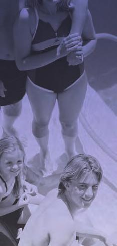
6 Preliminary WQMP for City Plaza Hotel II. Project Description Planning Area: None Project Size (ac): 2.60 Percent Change in Impermeable Surfaces: -3% Project Description The proposed development will consist of a 6-story hotel, approximately 165 rooms, with a pool deck and lobby. There is an existing ramp located near the south east portion of the project boundary that serves as a service access for the Outlets at Orange, which will be maintained in the existing condition. Proposed drive aisles will utilize a combination of asphalt while common areas will utilize concrete, turf, decorative tiling and landscaping. Waste generated will be typical of a commercial building/hotel. Some amenities included with this development are a large pool deck, fitness center, dining area and lobby. This development features 163 parking spaces available to the hotel. The south portion of the City Blvd East is also included in this project but will be preserved in the existing condition as much as feasible. The amount of pervious area and impervious proposed with this development is featured in the table below. Project Purpose and Activities Pervious Impervious Project Area Area (AC) % Area (AC) % Total Pre-Project % % 2.60 Post-Project % % 2.60 The purpose of this project is to redevelop the existing parking lot and bring temporary housing opportunities to nearby commercial entities. Overall, the proposed project reduces impervious areas within the project boundary. The entrance will be along City Blvd East and feature a drop off area for the hotel guests. Potential Storm Water Pollutants Suspended Solids/ Sediments, Nutrients, Heavy Metals, Pathogens, Pesticides, Oil and Grease, Toxic Organic Compounds, and Trash and Debris are expected to be of land use pollutants of concern based on Table 2.1. (Residential Development, Parking Lots, Streets) Project site will implement on-site LID BMPs in order to treat expected pollutants of concern. For Huntington Harbour, the listed 303(d) pollutants are Clordane, Copper, Lead, Nickel, PCBs, Pathogens, and Sediment Toxicity. For Anaheim Bay, the listed 303(d) pollutants are Dieldrin, Nickel, PCBs, Sediment Toxicity. Note that most are legacy pollutants that will not be generated by the project and no special treatment by the project BMPS is needed. November 2,
7 Preliminary WQMP for City Plaza Hotel Hydrologic Conditions of Concern The development of City Plaza Hotel is located near The Outlets of Orange in the City of Orange, California. The project site downstream conditions are all stable and are not susceptible to hydromodification. Post Development Drainage Characteristics Post development drainage will mimic the existing condition drainage. Currently, a majority of the site is utilizing infiltration planters along the south edge of City Blvd East and internally throughout the existing parking lot. From a drainage standpoint, any remaining runoff is tributary to an existing catch basin along Metropolitan Drive either via surface flow or grate inlet located in the center of the project. The runoff then enters the Lewis storm drain channel and discharges into the East Garden Grove Wintersburg Channel before ultimately reaching the outlet point in Huntington Harbor and Anaheim Bay. Hotel Projects The City Plaza Hotel features 165 rooms with approximately 14,000 sq. ft and a 5,100 sq ft pool deck. The hotel will consist of a lobby, lounge, dining area, office, fitness center, and 6-stories of hotel rooms. The front entrance will feature a dropoff turn in from City Blvd East. Site Ownership and any Easements There is an existing 82 Southern California Edison easement along the East of the proposed Hotel structure. There are also two 15 Domestic Water easements and a 15 Metropolitan Water District easement on the east side of the property. The proposed water quality treatment areas are not within these easements and therefore should not conflict with those easements or existing utilities. All existing and proposed easements can be seen in the Tentative Parcel Map in Appendix G. November 2,
8 Preliminary WQMP for City Plaza Hotel III. Site Description Site Address: 1 City Boulevard West Orange, California Zoning: UMU (Urban Mixed Use) Predominant Soil type: A Pre-project percent pervious: 17% Post-project percent pervious: 24% Pre-project percent impervious: 83% Post-project percent impervious:76% Site Characteristics The 2.60 acre site is located southeast of intersection of City Blvd. East and Entertainment Dr. in Orange, California. The project site, designated land use Urban Mixed Use, is bounded by the parking lots to the north, Metropolitan Drive to the south, parking lots to the east, and Entertainment Drive to the West. The site is relatively level with an approximate maximum elevation difference of 2 feet sloping down to the southwest. Currently, the site is developed with surface parking. The site is bounded on all sides with asphalt parking, drive aisles, and roadways. Some minor landscaping is present along the property lines and within the some of the islands dispersed throughout the parking lot. The predominant soil type is A according to the Web Soil Data Survey. Historic high groundwater is mapped at 35 feet below ground surface by the CGS and was not encountered in the borings conducted to a depth of 51.5 feet. A geotechnical due diligence for City Plaza Hotel was completed on August 10, 2016 which provided more detailed infiltration rates at proposed BMP locations. Watershed Characteristics Watershed: Santa Ana Region 8 (Westminster) Downstream Receiving Waters: Anaheim Bay, East Garden Grove Wintersburg Channel, Huntington Harbour, Bolsa Bay Water Quality Impairments (if applicable): For Huntington Harbour, the listed 303(d) pollutants are Clordane, Copper, Lead, Nickel, PCBs, Pathogens, and Sediment Toxicity. For Anaheim Bay, the listed 303(d) pollutants are Dieldrin, Nickel, PCBs, Sediment Toxicity. Note that most are legacy pollutants that will not be generated by the project and no special treatment by the project BMPS is needed. Identify hydromodification susceptibility: Downstream channels are all stable and therefore no hydromodification susceptibility anticipated. Identify watershed management priorities: N/A November 2,
9 Preliminary WQMP for City Plaza Hotel IV. Best Management Practices Currently the site utilizes bio-treatment planters dispersed throughout the site for water quality treatment. The site will propose the use of infiltration planters and one underground infiltration chamber. The utilization of underground infiltration chambers stemmed from a combination of allowing more parking spaces to be saved by pursuing underground BMPs, aesthetically pleasing planting opportunities for the hotel, and preserving as much landscaping areas possible along the frontage. If the infiltration planters had been utilized on the north side, the drainage would naturally be along the north edge of the property which the hotel would like to use as an entrance. Due to the low infiltration rate along the south edge of the property, infiltration planters will be utilized to supply the necessary water quality treatment. The pretreatment system associated with the underground chamber BMP will be a Kristar Dual Vortex Separator. An infiltration study was done near each respective BMP to calculate drawdown times. Vector issues are not anticipated because all BMPs are estimated to be drained in less than 96 hours and therefore no still water is anticipated. Furthermore, no hazardous materials are not anticipated on site. IV.1 Site Design and Drainage Characteristics Technique Minimize Directly Connected Impervious Areas (DCIAs) (C-Factor Reduction) Create Reduced or Zero Discharge Areas (Runoff Volume Reduction) 1 Minimize Impervious Area/Maximize Permeability (C-Factor Reduction) 2 Conserve Natural Areas (C-Factor Reduction) Table 1 Site Design BMPs Included? Yes No X X X X If no, state justification. No reduced/ zero discharge areas proposed. None to conserve. 1 Detention and retention areas incorporated into landscape design provide areas for retaining and detaining stormwater flows, resulting in lower runoff rates and reductions in volume due to limited infiltration and evaporation. Such Site Design BMPs may reduce the size of Treatment Control BMPs. 2 The C Factor is a representation of the ability of a surface to produce runoff. Surfaces that produce higher volumes of runoff are represented by higher C Factors. By incorporating more pervious, lower C Factor surfaces into a development, lower volumes of runoff will be produced. Lower volumes and rates of runoff translate directly to lowering treatment requirements. Minimize Directly Connected Impervious Areas The project site will minimize directly connected impervious areas by routing hotel roof drainage towards landscaping areas and dispersing the water with a splash block. Minimize Impervious Area/Maximize Permeability The proposed project impervious percentage is less than the pre-developed condition. November 2,
10 Preliminary WQMP for City Plaza Hotel IV.2 Source Control BMPs IV.2.1 Routine Non-Structural BMPs BMP No. N1 Name Education for Property Owners, Tenants and Occupants Table 2 Routine Non-Structural BMPs Included X Check One Not Applicable If not applicable, state brief reason. N2 Activity Restriction N3 Common Area Landscape Management N4 BMP Maintenance N5 Title 22 CCR Compliance N6 Local Water Quality Permit Compliance N7 Spill Contingency Plan N8 Underground Storage Tank Compliance N9 Hazardous Materials Disclosure Compliance N10 Uniform Fire Code Implementation N11 Common Area Litter Control N12 Employee Training N13 Housekeeping of Loading Docks N14 Common Area Catch Basin Inspection N15 Street Sweeping Private Streets and Parking Lots N16 Pet Waste X X X X X X X X X X X X X X X Hazardous materials not anticipated on-site. This BMP is not applicable. The City of Orange does not issue water quality permits. Hazardous material spills not anticipated on-site Underground storage tanks are not anticipated on-site. Hazardous materials not anticipated on-site. Hazardous materials not anticipated on-site. Loading docks are not anticipated on-site. November 2,
11 Preliminary WQMP for City Plaza Hotel N1 Education for Property Owners, Tenants, and Occupants Hotel to periodically provide environmental awareness of water quality impacts by distributing education materials, in Appendix B, to all of its contractors and employees. Among other things, these materials will describe the use of chemicals (including household type) that should be limited to the property, with no discharge of wastes via hosing or other direct discharge to gutters, catch basins and storm drains. N2 Activity Restrictions Some activities to be restricted would be appropriate parking areas, vehicle repair, and washing of pavement. Other activity restrictions, when appropriate. N3 Common Area Landscape Management Hotel to enforce and regulate on-going landscape maintenance requirements, such as inspection and preservation of conditions that are consistent with those in the City Guidelines. This includes fertilizer and/or pesticide usage consistent with City LIP Section 5 integrated pest management program. N4 BMP Maintenance BMP maintenance information provided in Appendix D. N11 Common Area Litter Control Hotel required to implement trash management and litter control procedures in the surrounding landscaping areas aimed at reducing pollution of drainage water. Hotel will ensure scheduled maintenance, litter patrol, emptying of trash receptacles, and noting trash disposals. N12 Employee Training Hotel to provide education for employees and contractors on stormwater quality management to be derived from educational materials available from the City of Orange resources and Appendix B. N14 Common Area Catch Basin Inspection All drainage systems, specifically catch basins and inlets, to be inspected and maintained free of sediment, trash, litter, and legibility of stencil. N15 Street Sweeping Private Streets and Parking Lots Street and parking lot sweeping to be required bi-monthly. Parking lot sweeping frequency will be increased based on usage and field observation of waste accumulation. November 2,
12 Preliminary WQMP for City Plaza Hotel IV.2.2 Routine Structural BMPs Name Provide storm drain system stenciling and signage- No Dumping Drains to Ocean Design and construct outdoor material storage areas to reduce pollution introduction Design and construct trash and waste storage areas to reduce pollution introduction Use efficient irrigation systems & landscape design Table 3 Routine Structural BMPs Included X X X Check One Not Applicable X If not applicable, state brief reason Outdoor material storage is not anticipated on-site. Protect slopes and channels and provide energy dissipation X No slopes and channels to protect. Incorporate requirements applicable to individual project features a. Dock areas X b. Maintenance bays X c. Vehicle or community wash areas X d. Outdoor processing areas X e. Equipment wash areas X f. Fueling areas X g. Hillside landscaping X h. Wash water control for food preparation areas X Covered dock areas are not anticipated on-site. Maintenance bays are not anticipated on-site. Vehicle wash areas are not anticipated on-site. Outdoor processing areas are not anticipated on-site. Equipment areas are not anticipated on-site. Fueling areas are not anticipated on-site. Hillsides are not anticipated onsite. Food preparation areas are not anticipated on-site. November 2,
13 Preliminary WQMP for City Plaza Hotel S1 Provide Storm Drain System Stenciling and Signage Storm drain stencils are highly visible source control messages, typically placed directly adjacent to storm drain inlets. The stencils contain a brief statement that prohibits the dumping of improper materials into the municipal storm drain system. Graphical icons, either illustrating anti-dumping symbols or images of receiving water fauna, are effective supplements to the antidumping message. Stencils and signs alert the public to the destination of pollutants discharged into stormwater. Following requirements shall be met. 1. Stenciling or labeling will be provided on all storm drain inlets and catch basins with language such as, NO DUMPING DRAINS TO OCEAN and/or graphical icons to discourage illegal dumping. 2. Post signs and prohibitive language and/or graphical icons, which prohibit illegal dumping at public access points along channels and creeks within the project area. 3. Maintain legibility of stencils and signs. S3- Design and construct trash and waste storage areas to reduce pollution introduction Trash areas will be roofed and screened/walled in a way to minimize exposure. The street will be sloped away from the trash enclosure thereby diverting around the trash areas to prevent run-on of storm water within trash enclosures. Signage on all dumpster informing users that hazardous materials are not to be disposed will be utilized. S4- Use efficient irrigation systems & landscape design, water conservation, smart controllers, and source control The project will apply methods of irrigation water to minimize the runoff of excess irrigation water into the municipal storm drain system. (The following methods to reduce excessive irrigation runoff shall be implemented and incorporated on common areas of development and other areas where determined applicable and feasible. 1. Employ rain shutoff devices to prevent irrigation after precipitation in courtyards. 2. Design irrigation systems to each landscape area s specific water requirements. 3. Using flow reducers or shutoff valves triggered by a pressure drop to control water loss in the event of broken sprinkler heads or lines along the landscaping on the edges of the residential building and the proposed parking structure. 4. Implementing landscape plan consistent with City of Orange s LIP, which may include provision of water sensors, programmable irrigation times (for short cycles), etc. 5. The project will choose plants with low irrigation requirements (for example, native or drought tolerant species) where appropriate and consider other design features, such as: Use mulches (such as wood chips or shredded wood products) in planter area without ground cover to minimize sediment in runoff, Install appropriate plant materials for the location, in accordance with amount of sunlight and climate, and use native plant material where possible and/or as recommended by the landscape architect 6. Leave a vegetative barrier along the property boundary and interior watercourses, to act as a pollutant filter, where appropriate and feasible, Choose plants that minimize or eliminate the use of fertilizer or pesticides to sustain growth. Irrigation practices shall comply with City of Orange ordinance irrigation efficiency. November 2,
14 Preliminary WQMP for City Plaza Hotel IV.3 Low Impact Development BMP Selection IV.3.1 Hydrologic Source Controls Table 4 Hydrologic Source Control BMPs Name Check If Used Localized on-lot infiltration Impervious area dispersion (e.g. roof top disconnection) Street trees (canopy interception) Residential rain barrels (not actively managed) Green roofs/brown roofs Blue roofs Infiltration BMP will be used to treat the full DCV. November 2,
15 Preliminary WQMP for City Plaza Hotel IV.3.2 Infiltration BMPs Table 5 Infiltration BMPs Name Check If Used Bioretention without underdrains Rain gardens Porous landscaping Infiltration planters Retention swales Infiltration trenches Infiltration basins Drywells Subsurface infiltration galleries French drains Permeable asphalt Permeable concrete Permeable concrete pavers Other: Other: DMA 1 will provide the necessary water quality treatment utilizing underground infiltration chambers while DMA 2 and 3 propose infiltration planters. The BMP Exhibit provided in section VI. In this report shows the outlet points of each of the DMAs and their respective locations. The proposed underground infiltration bmp is the Prinsco HS-180 or equivalent. The pretreatment selected for the chambers is a Kristar Dual Vortex Separator (DVS). Details of this BMP and its maintenance is provided in Appendix D. The proposed calculations for the underground infiltration bmps will be provided IV.8 of this report. Similarly to the existing condition, infiltration planters will be utilized for water quality treatment of DMA 2 and 3. A schematic of each infiltration planter can be found in Appendix C of this WQMP. There is existing infiltration planters that are being removed with the proposed site plan however, topographically there is no offsite drainage anticipated within the site boundary. As such, the project proposes to infiltrate and treat the entire Design Capture Volume for the project site which would naturally include any area that was previously being treated by the infiltration planters. November 2,
16 Preliminary WQMP for City Plaza Hotel IV.3.3 Evapotranspiration, Rainwater Harvesting BMPs Table 6 Evapotranspiration, Rainwater Harvesting BMP Name Check If Used All HSCs; See Section IV.3.1 Surface-based infiltration BMPs Biotreatment BMPs Above-ground cisterns and basins Underground detention Infiltration BMP will be used to treat the full DCV. IV.6 Vector Control No BMP will have potential for standing nuisance water (defined as drawdown time more than 96 hours) therefore vector control will not be necessary. November 2,
17 Preliminary WQMP for City Plaza Hotel IV.7 Drainage Management Area (DMA) DMA Number BMPs Area Treated 1 Underground Infiltration 0.79 ac Chamber 2 Infiltration Planter 1.63 ac 3 Infiltration Planter 0.18 ac Total Area 2.60 ac Total Project Area = 2.60 ac Note: The proposed BMPs treat the entire project site. November 2,
18 D M A IV.8 Calculations Units DMA Storm Depth Storm Depth Multiplier d (inches) Storm Depth Used sf % C A (SF) V (cu-ft) perv area imp Runoff Coefficient Tributary Area Preliminary WQMP for City Plaza Hotel Design Capture Volume Pretreatment % DVS % n/a % n/a In order to provide the necessary pretreatment (requirements per the OCTGD dated Dec. 20, 2013) and account for the full DCV with the proposed subsurface infiltration chambers, the following table was created to show compliance to the required LID DCV. The design infiltration rate was based on a geotechnical study, which can be found in Appendix E., divided by the required Factor of Safety value of 3.1 which was determined based on OCTGD requirements. The Factor of Safety worksheet can be found in Appendix G; along with all other necessary reference materials. A storm depth multiplier was applied to DMA 2 to increase the max drawdown time from 48 hours to 64 hours which increased the DCV and increased the maximum BMP depth allowed. The multiplier value was taken by utilizing Figure III.2 of the OCTGD dated Dec. 20, 2013 and a typical calculation was created and can be found in Appendix C. DMA 1 Proposed BMP HS-180 (7 chambers) DCV REQ. Design Inf Rate (in/hr) Stone Above (in) Chamber Depth (in) Stone Depth (in) BMP Depth (ft) BMP Area Prop. (sf) DCV Prop. (cf) Max Drawdown Time (hr) Typically, HS-180 chambers are 45.5 in height and laid upon a stone foundation with 40% porosity which can vary in depth. For DMA 1, the BMP depth was calculated by adding the height of the chambers and the 12 of stone foundation. The bottom of the chambers will be set at approximately 10 feet below finished surface. The amount of chambers were determined by utilizing the Design Aid Tool provided by Prinsco for the HS-180 model as shown in Appendix C. The drawdown times were calculated by multiplying the BMP depth by the design infiltration rates and the maximum drawdown times for each BMP was depicted on the table above. To see the calculations for the BMP depth and drawdown times, refer to Appendix C of this WQMP. For the sizing of the infiltration planters, the capture efficiency method was used to determine the required size for DMA 2 and 3. K(design) (in/hr) Prop. Footprint (ft) Media Depth (ft) Media Porosity Gravel Depth (ft) Gravel Porosity Pores Depth (ft) Ponding Depth (ft) Effective Depth (ft) Max Drawdown (hr) As such, the table above demonstrates that the full DCV volume required was met with the proposed subsurface infiltration chambers and infiltration planters proposed for City Plaza Hotel (see section IV of this report; BMP Exhibit). November 2,
19 Preliminary WQMP for City Plaza Hotel V. Implementation, Maintenance and Inspection Responsibility for BMPs (O&M Plan) Responsible Party Information: *Note: Prior to the Hotel management entity being created to manage the property, the below will be responsible for the implementation, maintenance and inspection. Name/Company: Scott Murray, Greenlaw partners Asset Manager Address: Von Karmon Ave #250 Irvine, CA Phone Number: (949) Table 8 - Frequency Inspection Matrix BMP Responsible Party Maintenance Activity Source Control BMPs (Structural and Non-structural) Storm Drain System Stenciling and Signage S1 Hotel Street Sweeping Trash/ Waste storage area Efficient Irrigation Education for property owners and employees Common Area Litter Control/ Trash Storage Common area Catch Basin Inspection Common Area Landscaping and Slopes N15 S3 S4 Hotel Hotel Hotel N1/N1 2 Hotel N11 N14 N3 Hotel Hotel Hotel All on-site storm drain inlets/catch basins will be labeled with No Dumping Drains to Ocean Replace labels as needed if label begins fading, becomes difficult to read, or dislodged. Perform mechanical street sweeping for streets within the project. Perform visual inspection to ensure trash area is appropriately emptied and signage for the trash area is clearly marked. Repair or replace any malfunctioning irrigation equipment as needed. Install shutoff devices and sensors to ensure conservation of water. Test monthly to ensure moisture sensors are working properly and over-spray is not occurring. Test entire system twice a year. Provide environmental awareness education materials made available by the city shall be distributed either by updated pamphlets in common areas or by mail to employees and contractors. Implement trash management and litter control procedures in common areas. This should consist of litter patrol and emptying trash receptacles Perform weekly visual inspection to ensure for legibility of stencil, and no blockage of sediment, trash and litter. Check vegetation for bare spots and ensure proper watering. Ensure implementation of efficient irrigation techniques as discussed in the WQMP. Replace bare areas and broken sprinklers as needed. Remove trash, sediment, debris, and invasive plant species as needed. Pet Waste N16 Hotel Check to ensure pet waste stations are stocked. Inspection Maintenance Frequency Bi-monthly Bi-monthly Monthly and increase frequency as needed. Weekly visual inspection and repair as needed. Test system twice a year. Within 60 days of hire (employees) and upon hire for contractors Weekly and increase frequency as needed. Weekly visual inspection and postrain event as needed Weekly and increase frequency as needed Weekly and increase frequency as needed November 2,
20 Preliminary WQMP for City Plaza Hotel Low Impact Development and Treatment BMPs Underground The underground infiltration chambers should be Infiltration inspected for infiltration performance (fouling, Chambers blockage, damage, equipment repair/maintenance, Hotel differential settlement, cracking, sediment accumulation, storage of accumulated sediment of Infiltration Planters Kristar Dual Vortex Separator (DVS) Hotel Hotel other wastes, and trash and debris. See Appendix D. The infiltration planters should be inspected for accumulation of waste, trash and debris and efficiency. The DVS s internal components should be inspected and noted whether there are any broken or missing parts. Observe, quantify, and record the accumulation of floating trash and debris, accumulation of oil and grease, accumulation of sediment in sediment storage sump. See Appendix D. Bi-yearly & after each significant rain event Bi-yearly & after each significant rain event Bi-yearly & after each significant rain event Funding After construction, a hotel management entity will be created and be responsible for property management including all post construction BMPs, maintenance, inspections and anything else pertaining to the upkeep of the property. Hotel revenue will be used for maintaining the property including, but not limited to, operations and maintenance of BMPs and CCRs. Internal storm drain systems will be privately maintained and managed by the hotel, while the domestic water and sewer lines will be dedicated to the City as public utilities. November 2,
21 Preliminary WQMP for City Plaza Hotel OWNER SELF CERTIFICATION STATEMENT As the owner representative of the City Plaza Hotel for which a Water Quality Management Plan (WQMP) was approved by the City, I hereby certify under penalty of law that all Best Management Practices contained within the approved Project WQMP have been maintained and inspected in accordance with the schedule and frequency outlined in the approved WQMP Maintenance Table. The maintenance activities and inspections conducted are shown in the attached table and have been performed by qualified and knowledgeable individuals. Structural Treatment BMPs have been inspected and certified by a licensed professional engineer. To the best of my knowledge, the information submitted is true and accurate and complete. I am aware that there are significant penalties for submitting false information, including the possibility of fines and citations for violating water quality regulations. Signed: Name: Title: Company: Address: Telephone Number: Date: November 2,
22 Preliminary WQMP for City Plaza Hotel BMP Implementation Tracking Table BMP Activity Completion Dates or Frequency Source Control BMPs (Structural and Nonstructural) All on-site storm drain inlets/catch Storm Drain System basins will be labeled with No Stenciling and Dumping Drains to Ocean. Replace Bi-monthly Signage labels as needed if label begins fading, becomes difficult to read, or dislodged. Trash/Waste Storage Street Sweeping Efficient Irrigation Education for property owners and employees Common Area Litter Control/ Common area Catch Basin Inspection Common Area Landscaping and Slopes Pet Waste Perform visual inspection to ensure trash area is appropriately emptied and signage for the trash area is clearly marked. Perform mechanical street sweeping for streets within the project. Repair or replace any malfunctioning irrigation equipment as needed. Install shutoff devices and sensors to ensure conservation of water. Test monthly to ensure moisture sensors are working properly and over-spray is not occurring. Test entire system twice a year. Provide environmental awareness education materials made available by the city shall be distributed either by updated pamphlets in common areas or by mail to employees and contractors. Implement trash management and litter control procedures in common areas. This should consist of litter patrol, emptying trash receptacles. Perform weekly visual inspection to ensure for legibility of stencil, and no blockage of sediment, trash and litter. Check vegetation for bare spots and ensure proper watering. Ensure implementation of efficient irrigation techniques as discussed in the WQMP. Replace bare areas and broken sprinklers as needed. Remove trash, sediment, debris, and invasive plant species as needed. Check to ensure pet waste stations are stocked. Monthly and increase frequency as needed. Bi-monthly Weekly visual inspection and repair as needed. Test system twice a year. Within 60 days of hire (employees) and upon hire for contractors Weekly and increase frequency as needed. Weekly visual inspection and post-rain event as needed Weekly and increase frequency as needed Weekly and increase frequency as needed Initial November 2,
23 Preliminary WQMP for City Plaza Hotel Low Impact Development and Treatment BMPs Underground The underground infiltration chambers Infiltration Chambers should be inspected for infiltration ** performance (fouling, blockage, damage, equipment repair/maintenance, differential settlement, cracking, sediment accumulation, storage of accumulated sediment of other wastes, and trash Infiltration Planters ** Kristar Dual Vortex Separator (DVS)** and debris. The infiltration planters should be inspected for accumulation of waste, trash and debris and efficiency. The DVS s internal components should be inspected and noted whether there are any broken or missing parts. Observe, quantify, and record the accumulation of floating trash and debris, accumulation of oil and grease, accumulation of sediment in sediment storage sump. Bi-yearly & after each significant rain event Bi-yearly & after each significant rain event Bi-yearly & after each significant rain event * This sheet is to be submitted annually with the Owner Self Certification Statement. ** Structural Treatment BMPs should be certified by a Licensed Professional Engineer. November 2,
24 Preliminary WQMP for City Plaza Hotel VI. Location Map, Site Plan, and BMP Details Additionally, See Appendix C for Site Plan and BMP Details. See Appendix G for Location Map. October 18,
25 SD SD SD SD SD SD SD SD SD SD SD SD SD SD SD SD HYDROSTOR HS180 CHAMBER PAVEMENT (PER ENGINEER'S DRAWINGS) 12" MIN 23.5" MIN. HS " 8' MAX. EMBEDMENT BACKFILL EXCAVATION WALL (SLOPED OR VERTICAL) 8" MIN. FOUNDATION 78" 12" SUITABLE SUBGRADE Alton Parkway Irvine, CA Phone: (949) MBAKERINTL.COM
26 PROJECT LOCATION HOTEL
27 Preliminary WQMP for City Plaza Hotel VII. Educational Materials Refer to the City s website or the Orange County Stormwater Program (ocwatersheds.com) for a library of materials available. Attach only the educational materials specifically applicable to the project. Education Materials Residential Material Check If Business Material Check If ( Applicable ( Applicable The Ocean Begins at Your Front Door Tips for the Automotive Industry Tips for Car Wash Fund-raisers Tips for Using Concrete and Mortar Tips for the Home Mechanic Tips for the Food Service Industry Homeowners Guide for Sustainable Water Use Proper Maintenance Practices for Your Business Household Tips Proper Disposal of Household Hazardous Waste Other Material Check If Attached Recycle at Your Local Used Oil Collection Center (North County) IC 3 Building Maintenance Recycle at Your Local Used Oil Collection Center (Central County) IC 4 Carpet Cleaning Recycle at Your Local Used Oil Collection Center (South County) IC 7 Landscape Maintenance Tips for Maintaining a Septic Tank System IC 10 Outdoor Loading/Unloading Responsible Pest Control IC 14 Painting, Finishing, and Coatings of Vehicles, Boats, Buildings, and Equipment Sewer Spill Response IC 15 Parking and Storage Tips for the Home Improvement Projects IC 16 Pool and Fountain Cleaning Tips for Horse Care IC 17 Spill Prevention and Clean up Tips for Landscaping and Gardening IC 22 Eating and Drinking Establishments Tips for Pet Care Tips for Pool Maintenance Tips for Residential Pool, Landscape and Hardscape Drains Tips for Projects Using Paint October 18,
28 Preliminary WQMP for City Plaza Hotel Appendix A: Conditions of Approval City Council Resolution dated August 22,
29 Preliminary WQMP for City Plaza Hotel Appendix B: Educational Material August 22,
30 Never allow pollutants to enter the street, gutter or storm drain! The Ocean Begins at Your Front Door


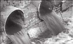
31 Even if you live miles from the Pacific Ocean, you may be unknowingly polluting it. Did You Know? Most people believe that the largest source of water pollution in urban areas comes from specific sources such as factories and sewage treatment plants. In fact, the largest source of water pollution comes from city streets, neighborhoods, construction sites and parking lots. This type of pollution is sometimes called non-point source pollution. There are two types of non-point source pollution: stormwater and urban runoff pollution. Stormwater runoff results from rainfall. When rainstorms cause large volumes of water to rinse the urban landscape, picking up pollutants along the way. Urban runoff can happen any time of the year when excessive water use from irrigation, vehicle washing and other sources carries trash, lawn clippings and other urban pollutants into storm drains. Where Does It Go? Sources of Non-Point Source Pollution Automotive leaks and spills. Improper disposal of used oil and other engine fluids. Metals found in vehicle exhaust, weathered paint, rust, metal plating and tires. Pesticides and fertilizers from lawns, gardens and farms. Improper disposal of cleaners, paint and paint removers. Soil erosion and dust debris from landscape and construction activities. Litter, lawn clippings, animal waste, and other organic matter. Oil stains on parking lots and paved surfaces. Dumping one quart of motor oil into a storm drain can contaminate 250,000 gallons of water. The Effect on the Ocean Non-point source pollution can have a serious impact on water quality in Orange County. Pollutants from the storm drain system can harm marine life as well as coastal and wetland habitats. They can also degrade recreation areas such as beaches, harbors and bays. Stormwater quality management programs have been developed throughout Orange County to educate and encourage the public to protect water quality, monitor runoff in the storm drain system, investigate illegal dumping and maintain storm drains. Support from Orange County residents and businesses is needed to improve water quality and reduce urban runoff pollution. Proper use and disposal of materials will help stop pollution before it reaches the storm drain and the ocean. Anything we use outside homes, vehicles and businesses like motor oil, paint, pesticides, fertilizers and cleaners can be blown or washed into storm drains. A little water from a garden hose or rain can also send materials into storm drains. Storm drains are separate from our sanitary sewer systems; unlike water in sanitary sewers (from sinks or toilets), water in storm drains is not treated before entering our waterways.

32 Never allow pollutants to enter the street, gutter or storm drain! Follow these simple steps to help reduce water pollution: Household Activities Do not rinse spills with water. Use dry cleanup methods such as applying cat litter or another absorbent material, sweep and dispose of in the trash. Take items such as used or excess batteries, oven cleaners, automotive fluids, painting products and cathode ray tubes, like TVs and computer monitors, to a Household Hazardous Waste Collection Center (HHWCC). For a HHWCC near you call (714) or visit Do not hose down your driveway, sidewalk or patio to the street, gutter or storm drain. Sweep up debris and dispose of it in the trash. Automotive Take your vehicle to a commercial car wash whenever possible. If you wash your vehicle at home, choose soaps, cleaners, or detergents labeled non-toxic, phosphate- free or biodegradable. Vegetable and citrus-based products are typically safest for the environment. Do not allow washwater from vehicle washing to drain into the street, gutter or storm drain. Excess washwater should be disposed of in the sanitary sewer (through a sink or toilet) or onto an absorbent surface like your lawn. Monitor your vehicles for leaks and place a pan under leaks. Keep your vehicles well maintained to stop and prevent leaks. Never pour oil or antifreeze in the street, gutter or storm drain. Recycle these substances at a service station, a waste oil collection center or used oil recycling center. For the nearest Used Oil Collection Center call CLEANUP or visit Pool Maintenance Pool and spa water must be dechlorinated and free of excess acid, alkali or color to be allowed in the street, gutter or storm drain. When it is not raining, drain dechlorinated pool and spa water directly into the sanitary sewer. Some cities may have ordinances that do not allow pool water to be disposed of in the storm drain. Check with your city. Landscape and Gardening Do not over-water. Water your lawn and garden by hand to control the amount of water you use or set irrigation systems to reflect seasonal water needs. If water flows off your yard onto your driveway or sidewalk, your system is over-watering. Periodically inspect and fix leaks and misdirected sprinklers. Do not rake or blow leaves, clippings or pruning waste into the street, gutter or storm drain. Instead, dispose of waste by composting, hauling it to a permitted landfill, or as green waste through your city s recycling program. Follow directions on pesticides and fertilizer, (measure, do not estimate amounts) and do not use if rain is predicted within 48 hours. Take unwanted pesticides to a HHWCC to be recycled. For locations and hours of HHWCC, call (714) or visit Trash Place trash and litter that cannot be recycled in securely covered trash cans. Whenever possible, buy recycled products. Remember: Reduce, Reuse, Recycle. Pet Care Always pick up after your pet. Flush waste down the toilet or dispose of it in the trash. Pet waste, if left outdoors, can wash into the street, gutter or storm drain. If possible, bathe your pets indoors. If you must bathe your pet outside, wash it on your lawn or another absorbent/permeable surface to keep the washwater from entering the street, gutter or storm drain. Follow directions for use of pet care products and dispose of any unused products at a HHWCC. Common Pollutants Home Maintenance Detergents, cleaners and solvents Oil and latex paint Swimming pool chemicals Outdoor trash and litter Lawn and Garden Pet and animal waste Pesticides Clippings, leaves and soil Fertilizer Automobile Oil and grease Radiator fluids and antifreeze Cleaning chemicals Brake pad dust

33 C lean beaches and healthy creeks, rivers, bays and ocean are important to Orange County. However, many common activities can lead to water pollution if you re not careful. Fertilizers, pesticides and other chemicals that are left on yards or driveways can be blown or washed into storm drains that flow to the ocean. Overwatering lawns can also send materials into storm drains. Unlike water in sanitary sewers (from sinks and toilets), water in storm drains is not treated before entering our waterways. You would never pour gardening products into the ocean, so don t let them enter the storm drains. Follow these easy tips to help prevent water pollution. For more information, please call the Orange County Stormwater Program at SPILL ( ) or visit UCCE Master Gardener Hotline: (714) To report a spill, call the Orange County 24-Hour Water Pollution Problem Reporting Hotline SPILL ( ). For emergencies, dial 911. The tips contained in this brochure provide useful information to help prevent water pollution while landscaping or gardening. If you have other suggestions, please contact your city s stormwater representatives or call the Orange County Stormwater Program. Printed on Recycled Paper


34 Tips for Landscape and & Gardening Never allow gardening products or polluted water to enter the street, gutter or storm drain. General Landscaping Tips Protect stockpiles and materials from wind and rain by storing them under tarps or secured plastic sheeting. Prevent erosion of slopes by planting fast-growing, dense ground covering plants. These will shield and bind the soil. Plant native vegetation to reduce the amount of water, fertilizers, and pesticide applied to the landscape. Never apply pesticides or fertilizers when rain is predicted within the next 48 hours. Garden & Lawn Maintenance Do not overwater. Use irrigation practices such as drip irrigation, soaker hoses or micro spray systems. Periodically inspect and fix leaks and misdirected sprinklers. Do not rake or blow leaves, clippings or pruning waste into the street, gutter or storm drain. Instead, dispose of green waste by composting, hauling it to a permitted landfill, or recycling it through your city s program. Use slow-release fertilizers to minimize leaching, and use organic fertilizers. Read labels and use only as directed. Do not over-apply pesticides or fertilizers. Apply to spots as needed, rather than blanketing an entire area. Store pesticides, fertilizers and other chemicals in a dry covered area to prevent exposure that may result in the deterioration of containers and packaging. Rinse empty pesticide containers and re-use rinse water as you would use the product. Do not dump rinse water down storm drains. Dispose of empty containers in the trash. When available, use non-toxic alternatives to traditional pesticides, and use pesticides specifically designed to control the pest you are targeting. For more information, visit If fertilizer is spilled, sweep up the spill before irrigating. If the spill is liquid, apply an absorbent material such as cat litter, and then sweep it up and dispose of it in the trash. Take unwanted pesticides to a Household Hazardous Waste Collection Center to be recycled. Locations are provided below. Household Hazardous Waste Collection Centers Anaheim: 1071 N. Blue Gum St. Huntington Beach: Nichols St. Irvine: 6411 Oak Canyon San Juan Capistrano: La Pata Ave. For more information, call (714) or visit

35 C lean beaches and healthy creeks, rivers, bays and ocean are important to Orange County. However, many common activities can lead to water pollution if you re not careful. Pet waste and pet care products can be washed into the storm drains that flow to the ocean. Unlike water in sanitary sewers (from sinks and toilets), water in storm drains is not treated before entering our waterways. You would never put pet waste or pet care products into the ocean, so don t let them enter the storm drains. Follow these easy tips to help prevent water pollution. For more information, please call the Orange County Stormwater Program at SPILL ( ) or visit To report a spill, call the Orange County 24-Hour Water Pollution Problem Reporting Hotline SPILL ( ). For emergencies, dial 911. The tips contained in this brochure provide useful information to help prevent water pollution while caring for your pet. If you have other suggestions, please contact your city s stormwater representatives or call the Orange County Stormwater Program. Printed on Recycled Paper


36 Tips for Pet Care Never let any pet care products or washwater run off your yard and into the street, gutter or storm drain. Washing Your Pets Even biodegradable soaps and shampoos can be harmful to marine life and the environment. If possible, bathe your pets indoors using less-toxic shampoos or have your pet professionally groomed. Follow instructions on the products and clean up spills. If you bathe your pet outside, wash it on your lawn or another absorbent/ permeable surface to keep the washwater from running into the street, gutter or storm drain. Flea Control Consider using oral or topical flea control products. If you use flea control products such as shampoos, sprays or collars, make sure to dispose of any unused products at a Household Hazardous Waste Collection Center. For location information, call (714) Why You Should Pick Up After Your Pet It s the law! Every city has an ordinance requiring you to pick up after your pet. Besides being a nuisance, pet waste can lead to water pollution, even if you live inland. During rainfall, pet waste left outdoors can wash into storm drains. This waste flows directly into our waterways and the ocean where it can harm human health, marine life and the environment. As it decomposes, pet waste demands a high level of oxygen from water. This decomposition can contribute to killing marine life by reducing the amount of dissolved oxygen available to them. Have fun with your pets, but please be a responsible pet owner by taking care of them and the environment. Take a bag with you on walks to pick up after your pet. Dispose of the waste in the trash or in a toilet.


37


38
39 IC3. BUILDING MAINTENANCE Pollution Prevention Consider pollution prevention measures at all times for improving pollution control. Implementation of pollution prevention measures may reduce or eliminate the need to implement other more costly or complicated procedures. The following pollution prevention principles apply to most industries: Affirmative Procurement - Use alternative, safer, or recycled products. Redirect storm water flows away from areas of concern. Reduce use of water or use dry methods. Reduce storm water flow across facility site. Recycle and reuse waste products and waste flows. Move or cover potential pollution from storm water contact. Provide on-going employee training in pollution prevention. Best Management Practices 1. Properly collect and dispose of water when pressure washing buildings, rooftops, and other large objects. 2. Properly prepare work area before conducting building maintenance. 3. Properly clean and dispose of equipment and wastes used and generated during building maintenance. 4. Employ soil erosion and stabilization techniques when exposing large areas of soil. 5. Store toxic material under cover when not in use and during precipitation events. 6. Properly dispose of fluids from air conditioning, cooling tower, and condensate drains. 7. Regularly inspect air emission control equipment under AQMD permit. 8. Train employees on these BMPs, storm water discharge prohibitions, and wastewater discharge requirements. OPTIONAL: 9. Switch to non-toxic chemicals for maintenance when possible. 10. Use chemicals that can be recycled. 1. Properly collect and dispose of water when pressure washing buildings, rooftops, and other large objects. If pressure washing where the surrounding area is paved, use a water collection device that enables collection of wash water and associated solids. Use a sump pump, wet vacuum or similarly effective device to collect the runoff and loose materials. Dispose of the collected runoff and solids properly. If pressure washing on a grassed area (with or without soap), runoff must be dispersed as sheet flow as much as possible, rather than as a concentrated stream. The wash runoff must remain on the grass and not drain to pavement. 2. Properly prepare work area before conducting building maintenance. Use ground or drop cloths underneath outdoor painting, scraping, and sandblasting work, and properly dispose of collected material daily. Use a ground cloth or oversized tub for activities such as paint mixing and tool cleaning. Use a storm drain cover, filter fabric, or similarly effective runoff control mechanism if dust, grit, wash water, or other pollutants may escape the work area and enter a storm drain. IC3 Building Maintenance 1
40 3. Properly clean and dispose of equipment and wastes used and generated during building maintenance. Clean paint brushes and tools covered with water-based paints in sinks connected to sanitary sewers or in portable containers that can be dumped into a sanitary sewer drain. Brushes and tools covered with non-water-based paints, finishes, or other materials must be cleaned in a manner that enables collection of used solvents (e.g., paint thinner, turpentine, etc.) for recycling or proper disposal. Properly dispose of wash water, sweepings, and sediments. Properly store equipment, chemicals, and wastes. Do not dump any toxic substance or liquid waste on the pavement, the ground, or toward a storm drain. OPTIONAL: Recycle residual paints, solvents, lumber, and other materials to the maximum extent practicable 4. Employ soil erosion and stabilization techniques when exposing large areas of soil. Confine excavated materials to pervious surfaces away from storm drain inlets, sidewalks, pavement, and ditches. Material must be covered if rain is expected. Use chemical stabilization or geosynthetics to stabilize bare ground surfaces. 5. Store toxic material under cover when not in use and during precipitation events. 6. Properly dispose of fluids from air conditioning, cooling tower, and condensate drains. 7. Regularly inspect air emission control equipment under AQMD permit. 8. Training 1. Train employees on these BMPs, storm water discharge prohibitions, and wastewater discharge requirements. 2. Train employees on proper spill containment and cleanup. Establish training that provides employees with the proper tools and knowledge to immediately begin cleaning up a spill. Ensure that employees are familiar with the site s spill control plan and/or proper spill cleanup procedures. BMP IC17 discusses Spill Prevention and Control in detail. 3. Establish a regular training schedule, train all new employees, and conduct annual refresher training. 4. Use a training log or similar method to document training. OPTIONAL: 9. Switch to non-toxic chemicals for maintenance when possible. If cleaning agents are used, select biodegradable products whenever feasible Consider using a waterless and non-toxic chemical cleaning method for graffiti removal (e.g. gels or spray compounds). 10. Use chemicals that can be recycled. Buy recycled products to the maximum extent practicable IC3 Building Maintenance 2
41 References California Storm Water Best Management Practice Handbooks. Industrial/Commercial Best Management Practice Handbook. Prepared by Camp Dresser& McKee, Larry Walker Associates, Uribe and Associates, Resources Planning Associates for Stormwater Quality Task Force. March King County Stormwater Pollution Control Manual. Best Management Practices for Businesses. King County Surface Water Management. July On-line: Stormwater Management Manual for Western Washington. Volume IV Source Control BMPs. Prepared by Washington State Department of Ecology Water Quality Program. Publication No August For additional information contact: City of Orange Public Works Department Surface Water Quality or visit our website: IC3 Building Maintenance 3
42 IC4. CARPET CLEANING Pollution Prevention Consider pollution prevention measures at all times for improving pollution control. Implementation of pollution prevention measures may reduce or eliminate the need to implement other more costly or complicated procedures. The following pollution prevention principles apply to most industries: Affirmative Procurement - Use alternative, safer, or recycled products. Redirect storm water flows away from areas of concern. Reduce use of water or use dry methods. Reduce storm water flow across facility site. Recycle and reuse waste products and waste flows. Move or cover potential pollution from storm water contact. Provide on-going employee training in pollution prevention. Best Management Practices Discharge wash water to sink, toilet, or other drain connected to the sanitary sewer system. Discharge wash water to sink, toilet, or other drain connected to the sanitary sewer system. Never discharge wash water to a street, gutter, parking lot, or storm drain. Either: - empty the spent cleaning fluid tank into a utility sink or other indoor sewer connection at the service provider s home base or - arrange with the customer to discharge into a toilet or utility sink on their premises. Check the local wastewater authority s requirements for discharge. Filter wash water before discharging to the sanitary sewer to avoid clogging pipes. Dispose of filtered material in the garbage, provided the carpet was not contaminated with hazardous materials. These guidelines apply even to cleaning products labeled nontoxic and biodegradable. Training 1. Train employees on these BMPs, storm water discharge prohibitions, and wastewater discharge requirements. 2. Train employees on proper spill containment and cleanup. Establish training that provides employees with the proper tools and knowledge to immediately begin cleaning up a spill. Ensure that employees are familiar with the site s spill control plan and/or proper spill cleanup procedures. BMP IC17 discusses Spill Prevention and Control in detail. 3. Establish a regular training schedule, train all new employees, and conduct annual refresher training. 4. Use a training log or similar method to document training. References Water Quality Guidelines for Carpet Cleaning Activities. Orange County Stormwater Program. Prepared by Watershed & Coastal Resources Division. January On-line: Orange County Stormwater Program Water Quality Guidelines for Carpet Cleaning Activities. March. IC4 Carpet Cleaning 1
43 For additional information contact: City of Orange Public Works Department Surface Water Quality or visit our website: IC4 Carpet Cleaning 2
44 IC7. LANDSCAPE MAINTENANCE Pollution Prevention Consider pollution prevention measures at all times for improving pollution control. Implementation of pollution prevention measures may reduce or eliminate the need to implement other more costly or complicated procedures. The following pollution prevention principles apply to most industries: Affirmative Procurement - Use alternative, safer, or recycled products. Redirect storm water flows away from areas of concern. Reduce use of water or use dry methods. Reduce storm water flow across facility site. Recycle and reuse waste products and waste flows. Move or cover potential pollution from storm water contact. Provide on-going employee training in pollution prevention. Best Management Practices 1. Take steps to reduce landscape maintenance requirements. 2. Properly store and dispose of gardening wastes. 3. Use mulch or other erosion control measures on exposed soils. 4. Properly manage irrigation and runoff. 5. Properly store and dispose of chemicals. 6. Properly manage pesticide and herbicide use. 7. Properly manage fertilizer use. 8. Train employees on these BMPs, storm water discharge prohibitions, and wastewater discharge requirements. OPTIONAL: 9. Incorporate integrated pest management techniques where appropriate. 1. Take steps to reduce landscape maintenance requirements. Where feasible, retain and/or plant native vegetation with features that are determined to be beneficial. Native vegetation usually requires less maintenance than planting new vegetation. When planting or replanting consider using low water use flowers, trees, shrubs, and groundcovers. OPTIONAL: Consider alternative landscaping techniques such as naturescaping and xeriscaping. 2. Properly store and dispose of gardening wastes. Dispose of grass clippings, leaves, sticks, or other collected vegetation as garbage at a permitted landfill or by composting. Do not dispose of gardening wastes in streets, waterways, or storm drainage systems. Place temporarily stockpiled material away from watercourses and storm drain inlets, and berm and/or cover. 3. Use mulch or other erosion control measures on exposed soils. 4. Properly manage irrigation and runoff. Irrigate slowly or pulse irrigate so the infiltration rate of the soil is not exceeded. Inspect irrigation system regularly for leaks and to ensure that excessive runoff is not occurring. If re-claimed water is used for irrigation, ensure that there is no runoff from the landscaped area(s). If bailing of muddy water is required (e.g. when repairing a water line leak), do not put it in the storm drain; pour over landscaped areas. IC7 Landscape Maintenance 1
45 OPTIONAL: Use automatic timers to minimize runoff. Use popup sprinkler heads in areas with a lot of activity or where pipes may be broken. Consider the use of mechanisms that reduce water flow to broken sprinkler heads. 5. Properly store and dispose of chemicals. Implement storage requirements for pesticide products with guidance from the local fire department and/or County Agricultural Commissioner. Provide secondary containment for chemical storage. Dispose of empty containers according to the instructions on the container label. OPTIONAL: Triple rinse containers and use rinse water as product. 6. Properly manage pesticide and herbicide use. Follow all federal, state, and local laws and regulations governing the use, storage, and disposal of pesticides and herbicides and training of applicators and pest control advisors. Follow manufacturers recommendations and label directions. Use pesticides only if there is an actual pest problem (not on a regular preventative schedule). When applicable use less toxic pesticides that will do the job. Avoid use of copper-based pesticides if possible. Use the minimum amount of chemicals needed for the job. Do not apply pesticides if rain is expected or if wind speeds are above 5 mph. Do not mix or prepare pesticides for application near storm drains. Prepare the minimum amount of pesticide needed for the job and use the lowest rate that will effectively control the targeted pest. Whenever possible, use mechanical methods of vegetation removal rather than applying herbicides. Use hand weeding where practical. Do not apply any chemicals directly to surface waters, unless the application is approved and permitted by the state. Do not spray pesticides within 100 feet of open waters. Employ techniques to minimize off-target application (e.g. spray drift) of pesticides, including consideration of alternative application techniques. Clean pavement and sidewalk if chemicals are spilled on these surfaces before applying irrigation water. When conducting mechanical or manual weed control, avoid loosening the soil, which could lead to erosion. OPTIONAL: Purchase only the amount of pesticide that you can reasonably use in a given time period. Careful soil mixing and layering techniques using a topsoil mix or composted organic material can be used as an effective measure to reduce herbicide use and watering. 7. Properly manage fertilizer use. Follow all federal, state, and local laws and regulations governing the use, storage, and disposal of fertilizers. Follow manufacturers recommendations and label directions. Employ techniques to minimize off-target application (e.g. spray drift) of fertilizer, including consideration of alternative application techniques. Calibrate fertilizer distributors to avoid excessive application. Periodically test soils for determining proper fertilizer use. IC7 Landscape Maintenance 2
46 8. Training Fertilizers should be worked into the soil rather than dumped or broadcast onto the surface. Clean pavement and sidewalk if chemicals are spilled on these surfaces before applying irrigation water. Sweep pavement and sidewalk if fertilizer is spilled on these surfaces before applying irrigation water. OPTIONAL: Use slow release fertilizers whenever possible to minimize leaching 1. Train employees on these BMPs, storm water discharge prohibitions, and wastewater discharge requirements. 2. Educate and train employees on the use of pesticides and pesticide application techniques. Only employees properly trained to use pesticides can apply them. 3. Train and encourage employees to use integrated pest management techniques. 4. Train employees on proper spill containment and cleanup. Establish training that provides employees with the proper tools and knowledge to immediately begin cleaning up a spill. Ensure that employees are familiar with the site s spill control plan and/or proper spill cleanup procedures. BMP IC17 discusses Spill Prevention and Control in detail. 5. Establish a regular training schedule, train all new employees, and conduct annual refresher training. 6. Use a training log or similar method to document training. OPTIONAL: 9. Incorporate the following integrated pest management techniques where appropriate: Mulching can be used to prevent weeds where turf is absent. Remove insects by hand and place in soapy water or vegetable oil. Alternatively, remove insects with water or vacuum them off the plants. Use species-specific traps (e.g. pheromone-based traps or colored sticky cards). Sprinkle the ground surface with abrasive diatomaceous earth to prevent infestations by soft-bodied insects and slugs. Slugs also can be trapped in small cups filled with beer that are set in the ground so the slugs can get in easily. In cases where microscopic parasites, such as bacteria and fungi, are causing damage to plants, the affected plant material can be removed and disposed of (pruning equipment should be disinfected with bleach to prevent spreading the disease organism). Small mammals and birds can be excluded using fences, netting, and tree trunk guards. Promote beneficial organisms, such as bats, birds, green lacewings, ladybugs, praying mantis, ground beetles, parasitic nematodes, trichogramma wasps, seedhead weevils, and spiders that prey on detrimental pest species. IC7 Landscape Maintenance 3
47 References California Storm Water Best Management Practice Handbooks. Industrial/Commercial Best Management Practice Handbook. Prepared by Camp Dresser& McKee, Larry Walker Associates, Uribe and Associates, Resources Planning Associates for Stormwater Quality Task Force. March King County Stormwater Pollution Control Manual. Best Management Practices for Businesses. King County Surface Water Management. July On-line: Stormwater Management Manual for Western Washington. Volume IV Source Control BMPs. Prepared by Washington State Department of Ecology Water Quality Program. Publication No August Water Quality Handbook for Nurseries. Oklahoma Cooperative Extension Service. Division of Agricultural Sciences and Natural Resources. Oklahoma State University. E-951. September For additional information contact: City of Orange Public Works Department Surface Water Quality or visit our website: IC7 Landscape Maintenance 4
48 IC10. OUTDOOR LOADING/UNLOADING OF MATERIALS Pollution Prevention Consider pollution prevention measures at all times for improving pollution control. Implementation of pollution prevention measures may reduce or eliminate the need to implement other more costly or complicated procedures. The following pollution prevention principles apply to most industries: Affirmative Procurement - Use alternative, safer, or recycled products. Redirect storm water flows away from areas of concern. Reduce use of water or use dry methods. Reduce storm water flow across facility site. Recycle and reuse waste products and waste flows. Move or cover potential pollution from storm water contact. Provide on-going employee training in pollution prevention. Best Management Practices 1. Properly design loading/unloading areas to prevent storm water runon, runoff of spilled liquids, etc. 2. Park vehicles and conduct loading/unloading only in designated loading/unloading areas so that spills or leaks can be contained. 3. Clean loading/unloading areas regularly to remove potential sources of pollutants. 4. Reduce exposure of materials to rain. 5. Use drip pans underneath hose and pipe connections and other leak-prone spots during liquid transfer operations, and when making and breaking connections. 6. Inspect equipment regularly. 7. If possible, conduct loading and unloading in dry weather. 8. Train employees on these BMPs, storm water discharge prohibitions, and wastewater discharge requirements. 1. Properly design loading/unloading areas to prevent storm water runon, runoff of spills, etc. Grade and/or berm the area to prevent runon. Position roof downspouts to direct stormwater away from the area. Grade and/or berm the loading/unloading area to a drain that is connected to a deadend. The area where truck transfers take place should be paved. If the liquid is reactive with the asphalt, Portland cement should be used to pave the area. Avoid placing loading/unloading areas near storm drains. 2. Park vehicles and conduct loading/unloading only in designated loading/unloading areas so that spills or leaks can be contained. 3. Clean loading/unloading areas regularly to remove potential sources of pollutants. This includes outside areas that are regularly covered by containers or other materials. 4. Reduce exposure of materials to rain. Cover the loading/unloading areas. If a cover is unfeasible, use overhangs, or seals or door skirts to enclose areas. 5. Use drip pans underneath hose and pipe connections and other leak-prone spots during liquid transfer operations, and when making and breaking connections. 6. Inspect equipment regularly Designate a responsible party to check under delivery vehicles for leaking fluids, spilled materials, debris, or other foreign materials. Check loading/unloading equipment regularly for leaks. 7. If possible, conduct loading and unloading in dry weather. IC10 Outdoor Loading/Unloading of Materials 1
49 8. Training 1. Train employees on these BMPs, storm water discharge prohibitions, and wastewater discharge requirements. 2. Train employees on proper spill containment and cleanup. Establish training that provides employees with the proper tools and knowledge to immediately begin cleaning up a spill. Ensure that employees are familiar with the site s spill control plan and/or proper spill cleanup procedures. BMP IC17 discusses Spill Prevention and Control in detail. 3. Train employees on the proper techniques used during liquid transfers to avoid leaks and spills. 4. Train forklift operators on the proper loading and unloading procedures. 5. Establish a regular training schedule, train all new employees, and conduct annual refresher training. 6. Use a training log or similar method to document training. References California Storm Water Best Management Practice Handbooks. Industrial/Commercial Best Management Practice Handbook. Prepared by Camp Dresser& McKee, Larry Walker Associates, Uribe and Associates, Resources Planning Associates for Stormwater Quality Task Force. March Model Urban Runoff Program: A How-To Guide for Developing Urban Runoff Programs for Small Municipalities. Prepared by City of Monterey, City of Santa Cruz, California Coastal Commission, Monterey Bay National Marine Sanctuary, Association of Monterey Bay Area Governments, Woodward-Clyde, Central Coast Regional Water Quality Control Board. July 1998 (Revised February 2002 by the California Coastal Commission). Stormwater Management Manual for Western Washington. Volume IV Source Control BMPs. Prepared by Washington State Department of Ecology Water Quality Program. Publication No August For additional information contact: City of Orange Public Works Department Surface Water Quality or visit our website: IC10 Outdoor Loading/Unloading of Materials 2
50 IC14. PAINTING, FINISHING, AND COATINGS OF VEHICLES, BOATS, BUILDINGS, AND EQUIPMENT Pollution Prevention 1. Use drop/ground cloths. 2. Shelter any blasting and spray painting activities. 3. Maintain a clean working environment. 4. Cover and seal nearby storm drain inlets. Consider pollution prevention measures at all times for improving pollution control. Implementation of pollution prevention measures may reduce or eliminate the need to implement other more costly or complicated procedures. The following pollution prevention principles apply to most industries: Affirmative Procurement - Use alternative, safer, or recycled products. Redirect storm water flows away from areas of concern. Reduce use of water or use dry methods. Reduce storm water flow across facility site. Recycle and reuse waste products and waste flows. Move or cover potential pollution from storm water contact. Provide on-going employee training in pollution prevention. Best Management Practices 5. Properly clean, store, and dispose of painting, finishing, and coating materials. 6. Train employees on these BMPs, storm water discharge prohibitions, and wastewater discharge requirements. 1. Use drop/ground cloths. Underneath outdoor painting, scraping, and sandblasting work. Underneath outdoor mixing of paints, solvents, and tool cleaning. 2. Shelter any blasting and spray painting activities. Hang wind-blocking tarps to prevent sand blasting dust and overspray from escaping. Do not conduct these activities when wind conditions are such that containment is rendered ineffective. Do not conduct these activities over open water. 3. Maintain a clean working environment. Utilize dry cleaning methods (e.g. sweeping). If washing is unavoidable, collect wash water for treatment and/or proper disposal. Vacuum loose paint chips and paint dust to prevent paint and other chemical substances from entering waters. Properly dispose of surface chips, used blasting sand, residual paints, and other materials. Use temporary storage containment that is not exposed to rain. 4. Cover and seal nearby storm drain inlets. Cover and seal nearby storm drain inlets with waterproof material, mesh, or other runoff control device. Leave covers in place until job is complete. Clean covers daily and remove any debris for proper disposal. IC14 Painting, Finishing, and Coating of Vehicles, 1 Boats, Buildings, and Equipment
51 5. Properly clean, store, and dispose of painting, finishing, and coating materials. Do not dispose of toxic substances or liquid wastes on the pavement, the ground, or toward a storm drain. Cover materials left outdoors at the end of the workday with a temporary waterproof covering made of polyethylene, polypropylene or hypalon. Clean paint brushes and tools covered with water-based paints in sinks connected to sanitary sewers or in portable containers that can be poured into a sanitary sewer drain. Clean paint brushes and tools covered with non-water-based paints, finishes, or other materials such that used solvents (e.g., paint thinner, turpentine, etc.) can be collected for recycling or proper disposal. OPTIONAL: Recycle paint, paint thinner, solvents, and other recyclable materials whenever possible. 6. Training 1. Train employees on these BMPs, storm water discharge prohibitions, and wastewater discharge requirements. 2. Train employees on proper spill containment and cleanup. Establish training that provides employees with the proper tools and knowledge to immediately begin cleaning up a spill. Ensure that employees are familiar with the site s spill control plan and/or proper spill cleanup procedures. BMP IC17 discusses Spill Prevention and Control in detail. 3. Establish a regular training schedule, train all new employees, and conduct annual refresher training. 4. Use a training log or similar method to document training. References California Storm Water Best Management Practice Handbooks. Industrial/Commercial Best Management Practice Handbook. Prepared by Camp Dresser& McKee, Larry Walker Associates, Uribe and Associates, Resources Planning Associates for Stormwater Quality Task Force. March King County Stormwater Pollution Control Manual. Best Management Practices for Businesses. King County Surface Water Management. July On-line: Stormwater Management Manual for Western Washington. Volume IV Source Control BMPs. Prepared by Washington State Department of Ecology Water Quality Program. Publication No August For additional information contact: City of Orange Public Works Department Surface Water Quality or visit our website: IC14 Painting, Finishing, and Coating of Vehicles, 2 Boats, Buildings, and Equipment
52 IC15. PARKING AND STORAGE AREA MAINTENANCE Pollution Prevention Consider pollution prevention measures at all times for improving pollution control. Implementation of pollution prevention measures may reduce or eliminate the need to implement other more costly or complicated procedures. The following pollution prevention principles apply to most industries: Affirmative Procurement - Use alternative, safer, or recycled products. Redirect storm water flows away from areas of concern. Reduce use of water or use dry methods. Reduce storm water flow across facility site. Recycle and reuse waste products and waste flows. Move or cover potential pollution from storm water contact. Provide on-going employee training in pollution prevention. Best Management Practices 1. Conduct regular cleaning. 2. Properly collect and dispose of wash water. 3. Consider use of source treatment BMPs to treat runoff. 4. Keep the parking and storage areas clean and orderly. 5. When cleaning heavy oily deposits: 6. When conducting surface repair work: 7. Conduct inspections on a regular basis. 8. Keep accurate maintenance logs to evaluate materials removed/stored and improvements made. 9. Arrange rooftop drains to prevent drainage directly onto paved surfaces. 10. Train employees on these BMPs, storm water discharge prohibitions, and wastewater discharge requirements. 1. Conduct regular cleaning. Sweeping or vacuuming the parking facility is encouraged over other methods. Sweep all parking lots at least once before the onset of the wet season. OPTIONAL: Establish frequency of sweeping based on usage and field observations of waste accumulation. 2. Properly collect and dispose of wash water. Block the storm drain or contain runoff. Wash water should be collected and pumped to the sanitary sewer or discharged to a pervious surface, do not allow wash water to enter storm drains. DO NOT discharge wash water to sanitary sewer until contacting the local sewer authority to find out if pretreatment is required. Dispose of parking lot sweeping debris and dirt at a landfill. 3. Consider use of source treatment BMPs to treat runoff. Allow sheet runoff to flow into biofilters (vegetated strip and swale) and/or infiltration devices. Utilize sand filters or oleophilic collectors for oily waste in low quantities. 4. Keep the parking and storage areas clean and orderly. Clean out and cover litter receptacles frequently to prevent spillage. Remove debris in a timely fashion. OPTIONAL: Post No Littering signs. 5. When cleaning heavy oily deposits: If possible, clean oily spots with absorbent materials. Do not allow discharges to the storm drain. Appropriately dispose of spilled materials and absorbents. IC15 Parking-Storage Area Maintenance 1
53 6. When conducting surface repair work: Pre-heat, transfer or load hot bituminous material away from storm drain inlets. Conduct surface repair work during dry weather to prevent contamination from contacting stormwater runoff. Cover and seal nearby storm drain inlets (with waterproof material or mesh) and manholes before applying seal coat, slurry seal, etc. Leave covers in place until job is complete and clean any debris for proper disposal. To avoid runoff, use only as much water as necessary for dust control. Use drip pans or absorbent material to catch drips from paving equipment that is not in use. Dispose of collected material and absorbents properly. 7. Conduct inspections on a regular basis. Designate personnel to conduct inspections of the parking facilities and stormwater conveyance systems associated with them. Inspect cleaning equipment/sweepers for leaks on a regular basis. 8. Keep accurate maintenance logs to evaluate materials removed/stored and improvements made. 9. Arrange rooftop drains to prevent drainage directly onto paved surfaces. 10. Training 1. Train employees on these BMPs, storm water discharge prohibitions, and wastewater discharge requirements. 2. Train employees on proper spill containment and cleanup. Establish training that provides employees with the proper tools and knowledge to immediately begin cleaning up a spill. Ensure that employees are familiar with the site s spill control plan and/or proper spill cleanup procedures. BMP IC17 discusses Spill Prevention and Control in detail. 3. Provide regular training to field employees and/or contractors regarding cleaning of paved areas and proper operation of equipment. 4. Establish a regular training schedule, train all new employees, and conduct annual refresher training. 5. Use a training log or similar method to document training. References California Storm Water Best Management Practice Handbooks. Industrial/Commercial Best Management Practice Handbook. Prepared by Camp Dresser& McKee, Larry Walker Associates, Uribe and Associates, Resources Planning Associates for Stormwater Quality Task Force. March King County Stormwater Pollution Control Manual. Best Management Practices for Businesses. King County Surface Water Management. July On-line: Model Urban Runoff Program: A How-To Guide for Developing Urban Runoff Programs for Small Municipalities. Prepared by City of Monterey, City of Santa Cruz, California Coastal Commission, Monterey Bay National Marine Sanctuary, Association of Monterey Bay Area Governments, Woodward-Clyde, Central Coast Regional Water Quality Control Board. July 1998 (Revised February 2002 by the California Coastal Commission). Stormwater Management Manual for Western Washington. Volume IV Source Control BMPs. Prepared by Washington State Department of Ecology Water Quality Program. Publication No August IC15 Parking-Storage Area Maintenance 2
54 For additional information contact: City of Orange Public Works Department Surface Water Quality or visit our website: IC15 Parking-Storage Area Maintenance 3
55 IC16. POOL AND FOUNTAIN CLEANING Pollution Prevention Consider pollution prevention measures at all times for improving pollution control. Implementation of pollution prevention measures may reduce or eliminate the need to implement other more costly or complicated procedures. 1. Prevent algae problems with regular cleaning, consistent adequate chlorine levels, and well-maintained water filtration and circulation systems. 2. Manage ph and water hardness to minimize corrosion of copper pipes. 3. Discharge pool and fountain water properly. 4. Properly clean and/or dispose of filters. 5. Train employees on these BMPs, storm water discharge prohibitions, and wastewater discharge requirements. The following pollution prevention principles apply to most industries: Affirmative Procurement - Use alternative, safer, or recycled products. Redirect storm water flows away from areas of concern. Reduce use of water or use dry methods. Reduce storm water flow across facility site. Recycle and reuse waste products and waste flows. Move or cover potential pollution from storm water contact. Provide on-going employee training in pollution prevention. Best Management Practices 1. Prevent algae problems with regular cleaning, consistent adequate chlorine levels, and well-maintained water filtration and circulation systems. Do not use copper-based algaecides. Control algae with chlorine or other alternatives, such as sodium bromide. 2. Manage ph and water hardness to minimize corrosion of copper pipes. 3. Discharge pool and fountain water properly. Consider hiring a professional pool-draining service to collect all pool water for off-site disposal. If this is not feasible, adhere to the following: When draining pools or fountains never discharge water to a street or storm drain, discharge to the sanitary sewer if permitted to do so. If draining a pool to the sanitary sewer, prevent backflow by maintaining an air gap between the discharge line and the sewer line (do not seal the connection between the hose and sewer line). Be sure to call the local sewer authority for guidance on flow rate restrictions, backflow prevention, and handling special cleaning waste (such as acid wash). Keep discharge flows to the low levels. Higher flow rates may be prohibited by local ordinance. If water is dechlroinated with a neutralizing chemical or by allowing chlorine to dissipate for a few days (do not use the facility during this time), the water may be recycled/reused by draining it gradually onto a landscaped area. Water must be tested prior to discharge to ensure that chlorine is not present. Provide drip pans or buckets beneath drain pipe connections to catch leaks. This will be especially pertinent if pool or spa water that has not been dechlorinated is pumped through piping to a discharge location. IC16 Pool and Fountain Cleaning 1
56 4. Properly clean and/or dispose of filters. Never clean a filter in the street or near a storm drain. Rinse cartridge filters onto a dirt area, and work filter residue into soil. Backwash diatomaceous earth filters onto dirt. Dispose of spent diatomaceous earth in the garbage. Diatomaceous earth cannot be discharged to surface waters, storm drainage systems, septic systems, or on the ground. If there is not a suitable dirt area, discharge filter backwash or rinsewater to the sanitary sewer if permitted to do so by the local sewering agency. 5. Training 1. Train employees on these BMPs, storm water discharge prohibitions, and wastewater discharge requirements. 2. Train employees on proper spill containment and cleanup. Establish training that provides employees with the proper tools and knowledge to immediately begin cleaning up a spill. Ensure that employees are familiar with the site s spill control plan and/or proper spill cleanup procedures. BMP IC17 discusses Spill Prevention and Control in detail. 3. Train maintenance personnel on the proper techniques for testing chlorine levels and applying neutralizing chemicals. 4. Establish a regular training schedule, train all new employees, and conduct annual refresher training. 5. Use a training log or similar method to document training. References King County Stormwater Pollution Control Manual. Best Management Practices for Businesses King County Surface Water Management. July. On-line: Los Angeles County Stormwater Quality. Public Agency Activities Model Program. On-line: Model Urban Runoff Program: A How-To Guide for Developing Urban Runoff Programs for Small Municipalities. Prepared by City of Monterey, City of Santa Cruz, California Coastal Commission, Monterey Bay National Marine Sanctuary, Association of Monterey Bay Area Governments, Woodward-Clyde, Central Coast Regional Water Quality Control Board. July 1998 (Revised February 2002 by the California Coastal Commission). Santa Clara Valley Urban Runoff Pollution Prevention Program. Maintenance Best Management Practices for the Construction Industry. Brochures: Landscaping, Gardening, and Pool; Roadwork and Paving; and Fresh Concrete and Mortar Application. June For additional information contact: City of Orange Public Works Department Surface Water Quality or visit our website: IC16 Pool and Fountain Cleaning 2
57 IC17. SPILL PREVENTION AND CLEANUP Pollution Prevention Consider pollution prevention measures at all times for improving pollution control. Implementation of pollution prevention measures may reduce or eliminate the need to implement other more costly or complicated procedures. The following pollution prevention principles apply to most industries: Affirmative Procurement - Use alternative, safer, or recycled products. Redirect storm water flows away from areas of concern. Reduce use of water or use dry methods. Reduce storm water flow across facility site. Recycle and reuse waste products and waste flows. Move or cover potential pollution from storm water contact. Provide on-going employee training in pollution prevention. Best Management Practices Spill Prevention 1. Develop procedures to prevent/mitigate spills to storm drain systems. 2. Post No Dumping signs with a phone number for reporting illegal dumping and disposal. 3. Conduct routine cleaning, inspections, and maintenance. 4. Properly store and handle chemical materials. 5. Utilize secondary containment systems for liquid materials. 6. Protect materials stored outside from stormwater runon. 7. Secure drums stored in an area where unauthorized persons may gain access to prevent accidental spillage, pilferage, or any unauthorized use. 8. Identify key spill response personnel. 9. Adopt the Orange County Hazardous Materials Area Plan or an equivalent plan. 10. Clean up leaks and spills immediately. 11. Report and track spills. 12. Train employees on these BMPs, storm water discharge prohibitions, and wastewater discharge requirements. 1. Develop procedures to prevent/mitigate spills to storm drain systems. Standardize reporting procedures, containment, storage, and disposal activities, documentation, and follow-up procedures. 2. Post No Dumping signs with a phone number for reporting illegal dumping and disposal. Signs should also indicate fines and penalties applicable for illegal dumping. 3. Conduct routine cleaning, inspections, and maintenance. Sweep and clean storage areas consistently at a designated frequency (e.g. weekly, monthly). DO NOT hose down areas to storm drains. Place drip pans or absorbent materials beneath all mounted taps, and at all potential drip and spill locations during filling and unloading of tanks. Reuse, recycle, or properly dispose of any collected liquids or soiled absorbent materials. Check tanks (and any containment sumps) frequently for leaks and spills. Replace tanks that are leaking, corroded, or otherwise deteriorating with tanks in good condition. Collect all spilled liquids and properly dispose of them. Check for external corrosion of material containers, structural failures, spills and overfills due to operator error, failure of piping system, etc. Inspect tank foundations, connections, coatings, and tank walls and piping system. IC17 Spill Prevention and Control 1
58 4. Properly store and handle chemical materials. Designate a secure material storage area that is paved with Portland cement concrete, free of cracks and gaps, and impervious in order to contain leaks and spills. Do not store chemicals, drums, or bagged materials directly on the ground. Place these items in secondary containers. Keep chemicals in their original containers, if feasible. Keep containers well labeled according to their contents (e.g., solvent, gasoline). Label hazardous substances regarding the potential hazard (corrosive, radioactive, flammable, explosive, poisonous). Prominently display required labels on transported hazardous and toxic materials (per US DOT regulations). 5. Utilize secondary containment systems for liquid materials. Surround storage tanks with a berm or other secondary containment system. Slope the area inside the berm to a drain. Drain liquids to the sanitary sewer if available. Pass accumulated stormwater in petroleum storage areas through an oil/water separator. Use catch basin filtration inserts. DO NOT discharge wash water to sanitary sewer until contacting the local sewer authority to find out if pretreatment is required. If the liquid is oil, gas, or other material that separates from and floats on water, install a spill control device (such as a tee section) in the catch basins that collect runoff from the storage tank area. 6. Protect materials stored outside from stormwater runon. Construct a berm around the perimeter of the material storage area to prevent the runon of uncontaminated stormwater from adjacent areas as well as runoff of stormwater from the material. 7. Secure drums stored in an area where unauthorized persons may gain access to prevent accidental spillage, pilferage, or any unauthorized use. Spill Control and Cleanup Activities 8. Identify key spill response personnel. 9. Adopt the Orange County Hazardous Materials Area Plan or an equivalent plan, which includes a set of planned responses to hazardous materials emergencies addressing chain-of-command, public agency participation, and allocation of authority. The plan should include such items as: Description of the facility, owner and address, activities and chemicals present Facility map Notification and evacuation procedures Cleanup instructions Identification of responsible departments IC17 Spill Prevention and Control 2
59 IC22. EATING AND DRINKING ESTABLISHMENTS Pollution Prevention Consider pollution prevention measures at all times for improving pollution control. Implementation of pollution prevention measures may reduce or eliminate the need to implement other more costly or complicated procedures. The following pollution prevention principles apply to most industries: Affirmative Procurement - Use alternative, safer, or recycled products. Redirect storm water flows away from areas of concern. Reduce use of water or use dry methods. Reduce storm water flow across facility site. Recycle and reuse waste products and waste flows. Move or cover potential pollution from storm water contact. Provide on-going employee training in pollution prevention. Best Management Practices 1. Practice good housekeeping. 2. Clean equipment (floor mats, grease filters, grills, garbage cans, etc.) indoors or in a covered outdoor wash area that is plumbed to the sanitary sewer or in an area that will contain the wash water. 3. Recycle and/or properly dispose of grease and oil. 4. Block the storm drain when hosing or steam/pressure washing outside dumpster areas, sidewalks, and common areas with hot water, soap, or other cleaning agent. 5. If only tap water and no cleaning agents are used sweep area, clean up spills, direct water to vegetative area or collect and properly dispose of it contaminated. 6. Train employees on these BMPs, storm water discharge prohibitions, and wastewater discharge requirements. 1. Practice good housekeeping. Conduct regular sweeping or vacuuming of outdoor areas: Dry sweep pavement areas including drive-thru areas, parking lots, sidewalks, outdoor eating areas and dumpster storage areas frequently. Keep outside areas free of trash & debris. Do not hose out dumpsters or fill them with liquid waste. Regularly inspect, repair, and/or replace dumpsters. 2. Clean equipment (floor mats, grease filters, grills, garbage cans, etc.) indoors or in a covered outdoor wash area that is plumbed to the sanitary sewer. Clean equipment in a mop sink if possible (never in a food preparation sink). If there is no mop sink, dedicate an indoor cleaning area where a drain is plumbed to the sanitary sewer. Dispose mop water from cleaning floors in a mop sink, toilet or other drain that is plumbed to the sanitary sewer. Do not pour wash water outside or into a street, gutter, or storm drain. Dispose of all wastewater containing oil and grease in a grease trap or interceptor. 3. Recycle and/or properly dispose of grease and oil. Collect and dispose of concentrated waste oil and grease and disposed of by a certified waste grease hauler. NEVER pour grease or oil into a sink, floor drain, storm drain or dumpster.
60 4. Block storm drain(s) when cleaning (hosing or steam/pressure washing) outside dumpster areas, sidewalks, and common areas with hot water, soap, or other cleaning agent. Collect water/waste and discharge to the sanitary sewer (with approval of the local sanitation district). 5. If only cold tap water with no cleaning agents are used, then the following must be implemented: 6. Training Prior to washing clean and/or sweep all large debris from the area. Clean any fluid spills with an appropriate dry method, such as kitty litter or other absorbent, and dispose of appropriately. To the extent practicable, the wash water must be directed to vegetative or unpaved areas where it would soak into the ground. If wash water appears contaminated (cloudy, colored, presence of suspended solids), additional BMPs such as diversion to the sanitary sewer (with approval) or filtration methods must be implemented. 1. Train employees on these BMPs, storm water discharge prohibitions, and wastewater discharge requirements. 2. Train employees on proper spill containment and cleanup. Establish training that provides employees with the proper tools and knowledge to immediately begin cleaning up a spill. Ensure that employees are familiar with the site s spill control plan and/or proper spill cleanup procedures. BMP IC17 discusses Spill Prevention and Control in detail. 3. Establish a regular training schedule, train all new employees, and conduct annual refresher training. 4. Use a training log or similar method to document training. References Carlsbad Jurisdictional Urban Runoff Management Plan. Best Management Practices for Restaurants. City of Carlsbad. February On-line: Orange County Stormwater Program Water Quality Guidelines for Exterior Restaurant Cleaning Operations. Brochure. June. Orange County Stormwater Program. Good Cleaning Practices Food & Restaurant Industry. Poster. Courtesy of the City and County of LA. For additional information contact: City of Orange Public Works Department Surface Water Quality or visit our website:
61 Preliminary WQMP for City Plaza Hotel Appendix C: BMP Details & Exhibit August 22,
62 SD SD SD SD SD SD SD SD SD SD SD SD SD SD SD SD HYDROSTOR HS180 CHAMBER PAVEMENT (PER ENGINEER'S DRAWINGS) 12" MIN 23.5" MIN. HS " 8' MAX. EMBEDMENT BACKFILL EXCAVATION WALL (SLOPED OR VERTICAL) 8" MIN. FOUNDATION 78" 12" SUITABLE SUBGRADE Alton Parkway Irvine, CA Phone: (949) MBAKERINTL.COM
 18 Additional Stone Below Chamber* (in) Number of Manifolds Width 11 1 Stone Porosity (ft) Additional")
 Standard Min. Pavement Elevation 8 * Minimum recommended values are already included in calculations SYSTEM LAYOUT Pavement Avg. Depth Final Backfill 23.5\" Initial Backfill 2.")

63 PROJECT DESCRIPTION Project Name: Date: Engineer: / / City/State: Contractor: / Phone #: Designed By: Prinsco Rep: DESIGN CRITERIA - BASED ON STORAGE VOLUME Chamber Size Constraint on System Dimensions HS180 Target Storage 1705 Additional Stone Above Chamber* 0 Constraint Limit (cf) 18 Additional Stone Below Chamber* (in) Number of Manifolds Width 11 1 Stone Porosity (ft) Additional Stone Side of Chamber* (in) Manifold Diameter 40 0 Include Manifold Volume? (in) Bottom of Stone Elevation 0 (ft) Additional Stone Between Chambers* 0 (in) % (in) 12 Units Yes Max. Pvement Elevation 8 (ft) Standard Min. Pavement Elevation 8 * Minimum recommended values are already included in calculations SYSTEM LAYOUT Pavement Avg. Depth Final Backfill 23.5" Initial Backfill 2.5' 12" Embedment 45.5" Stone Foundation Non-woven 20" Suitable 77.8" 12" 8" Min. Burial Depth: 23.5" Max. Burial Depth: 8' WARNING: Burial Depth Too Shallow WARNING: Burial Depth Exceeds Recommendation SYSTEM STORAGE & QUANTITIES System Footprint System Layout 1 of rows 4 chambers Number of Chambers 7 & 1 of rows (sf) Stone Storage 957 Manifold Storage 13 (cf) Chamber Storage (cf) 871 Total System Storage (cf) 1842 chambers Number of End Caps 4 Required Stone Non-Woven Geotextile Woven Geotextile - Scour Woven Geotextile - Sediment Row (For Embedment Backfill) (Includes 20% Overlap) (Includes 20% Overlap) (Includes 20% Overlap) (cy) (sy) (sy) 76 (sy) ASSISTANCE: For assistance with design, drawings or pricing please have your completed system design aid ready, and contact your Prinsco sales representative Prinsco, Inc. I th St NE I Willmar, MN I I I prinsco.com This tool is intended to assist in sizing stormwater management systems using Prinsco products. It should be used for estimating purposes only and is not intended to be a final design tool. The design engineer needs to verify all the values and ensure they meet all project design criteria. (cf) (ft)
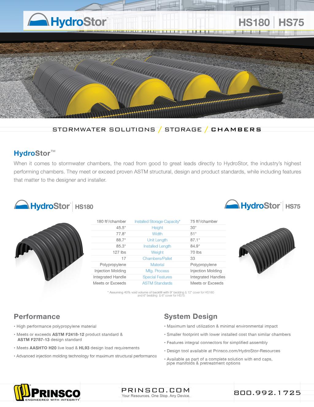
64

65
66
67
68 DCV REQ. / EFFECTIVE DEPTH = PROP. FOOTPRINT (FT)


69 Dual Vortex Separator Hydrodynamic Separation Hydrodynamic Enhanced gravity separation of stormwater pollutants in a compact configuration Maintenance Accessible Design Open access to accumulated floatables and two access points to sediment storage area. Economical Installation Prepackaged and provided in a compact manhole or small vault. Access Options Multiple access options (manhole cover(s) or optional hinged lid) allow for site-specific customization. Online System Capability Internal high-flow bypass weir system provides for online or offline configurations. Hydrodynamic Separation The Dual Vortex Separator (DVS) offers an innovative and economic alternative for BMP implementation in new and retrofit applications where space is limited and effective stormwater treatment is required. The DVS unit can be used to help meet TMDL requirements for removal of sediment, gross solids, petroleum hydrocarbons, and trash. The unit can also be a critical component of a comprehensive LID strategy, providing pretreatment to help increase the service life of detention, retention, and infiltration systems as well as other stormwater treatment BMPs. Durable Construction Stainless steel components installed in a reinforced concrete structure. Proven Performance Third party tested and certified. Treatment Train Configurations Dual Vortex Separator can be installed upstream of infiltration, detention, and retention systems or other treatment BMPs. NJCAT VERIFIED NJDEP CERTIFIED Dual Vortex Separator performance has been verified by NJCAT, one of the most comprehensive, rigorous, and recognized verification programs in the United States, and has been certified by NJDEP. Stormwater Solutions


 2.5 3.0 3.5 4.5 5.0 5.5 7.0 8.")
70 Dual Vortex Separator How it Works Particle settling is enhanced by centrifugal forces induced by circular flow patterns in the twin vortex chambers and an extended flow path which maximizes hydraulic residence time. Settled solids are collected in an isolated storage area at the bottom of the structure, while floating trash, debris, and petroleum hydrocarbons are retained behind baffles that contain the vortex chambers. During peak runoff events, flow in excess of design treatment flow overtops the bypass weir and exits the system without entering the treatment chambers to interrupt the treatment process or re-entrain captured pollutants. DVS with trapped pollutants Hydrodynamic Hydrodynamic Separation Site-Specific Design The Dual Vortex Separator is sized to meet site-specific requirements for treatment efficiency. Model selection is typically based on a mean particle size and target removal percentage as prescribed by the jurisdictional agency. Local rainfall data may also be used to support model selection. DVS units may be configured online or offline depending on agency requirements or the hydraulic capacity of the system. Oldcastle Stormwater Solutions engineering team will help determine the appropriate application for your site. Round configuration Structure Model No. Diameter (ft.) DVS-36 3 DVS-48 4 DVS-60 5 DVS-72 6 DVS-84 7 DVS-96 8 DVS DVS Models and Nominal Dimensions Sump Depth* (ft.) *Depth of unit can be increased to add storage capacity Minimum Rim to Invert Depth (ft.) Sediment Storage* (cubic feet) Oil and Floatables Storage (cubic feet) Square configuration Available Options Square configurations to accept multiple inlet pipes or other special site conditions Removable internals Flume inlet control for grated inlet applications Maintenance Dual access to sediment storage areas Easy access to floatable collection areas Modular construction of components Large interior work areas Recommended inspection frequency- twice per year oldcastlestormwater.com (800) /20/2015_V5 stormcapture.com 2015 Oldcastle Precast, Inc.
71 Preliminary WQMP for City Plaza Hotel Appendix D: BMP Maintenance Information August 22,


72 INSPECTION AND MAINTENANCE GUIDE (800) An Oldcastle Precast Company
73 An Oldcastle Precast Company Dual Vortex Separator - Inspection and Maintenance Guide 2 Description The Dual Vortex Separator (DVS) is a hydrodynamic stormwater treatment device used to remove pollutants from urban runoff. Impervious surfaces and other urban and suburban landscapes generate a variety of contaminants that can enter stormwater and pollute downstream receiving waters. The DVS is designed to capture and retain sediment as well as floating trash, debris, and oils. The concentration of metals and other constituents associated with the sediment or floating pollutants may also be reduced. Function Stormwater runoff enters the DVS unit through an inlet pipe. Influent flow is split evenly between two vortex tubes by a V-shaped weir. The shape and diameter of the vortex tubes promotes circular motion of the incoming stormwater at increased velocities to enhance particle settling through centrifugal force. The system is also designed with an extended flow path to maximize hydraulic residence time which allows increased time to settle out solids. Settled pollutants are collected in an isolated storage area at the bottom of the structure, while floating trash, debris, and petroleum hydrocarbons are retained behind baffles that contain the vortex chambers. During peak runoff events, flow in excess of design treatment flow overtops the bypass weir and exits the system without entering the treatment chambers to interrupt the treatment process or re-entrain captured pollutants. Treatment and bypass flows exit the system through an outlet pipe that is plumbed at the same elevation as the inlet pipe. Configuration The internal components of the DVS system are fabricated from stainless steel and mounted in a manhole or vault structure. The system is typically delivered as a complete unit for installation by the contractor. Installation includes excavation, preparation of the base rock, setting the unit, plumbing the inlet and outlet piping, backfill, and placement of the finished surface at grade. Access to the installed system is allowed through ductile iron casting or hatch covers. The number of access points provided is dependent on the size and configuration of the system. Maintenance Overview State and Local regulations require all stormwater management systems to be inspected on a regular basis and maintained as necessary to ensure performance and protect downstream receiving waters. Without maintenance, excessive pollutant buildup can limit system performance by reducing the operating capacity and increase the potential for scouring of pollutants during periods of high flow. (800)
74 An Oldcastle Precast Company Dual Vortex Separator - Inspection and Maintenance Guide 3 Inspection Equipment The following equipment is helpful when conducting DVS inspections: Recording device (pen and paper form, voice recorder, ipad, etc.) Suitable clothing (appropriate footwear, gloves, hardhat, safety glasses, etc.) Traffic control equipment (cones, barricades, signage, flagging, etc.) Manhole hook or pry bar Flashlight Tape measure Measuring stick or sludge sampler Long-handled net (optional) Replacement sorbent pads Inspection Procedures Inspection is essential to consistent system performance and is easily completed. Inspection is typically conducted a minimum of twice per year but since pollutant transport and deposition varies from site to site, a site-specific maintenance frequency should be established during the first two or three years of operation. DVS inspections are visual and are conducted without entering the unit. To complete an inspection, safety measures including traffic control should be deployed before the access covers are removed. Once the covers have been removed, the following items should be checked and recorded (see form provided on page 6) to determine whether maintenance is required: Inspect the internal components and note whether there are any broken or missing parts. In the unlikely event that internal parts are broken or missing, contact Oldcastle Stormwater Solutions at (800) to determine appropriate corrective action. Note whether the inlet or outlet pipe is blocked or obstructed. Observe, quantify, and record the accumulation of floating trash and debris in the baffled chambers around the vortex tubes. The significance of accumulated floating trash and debris is a matter of judgment. A long-handled net may be used to retrieve the bulk of trash and debris at the time of inspection if full maintenance due to accumulation of oils or sediment is not yet warranted. Observe, quantify, and record the accumulation of oils in the baffled chambers around the vortex tubes. If sorbent pads have been used to absorb free oil and grease, observe and record their condition. Unless the sorbent pads are tethered to the internal baffles, spent pads may be netted and replaced at the time of inspection. The significance of accumulated floating oils is a matter of judgment. However, if there is evidence of an oil or fuel spill, immediate maintenance is warranted. (800)
75 An Oldcastle Precast Company Dual Vortex Separator - Inspection and Maintenance Guide 4 Inspection Procedures - continued Finally, observe, quantify, and record the accumulation of sediment in the sediment storage sump. A calibrated dipstick, tape measure, or sludge sampler may be used to determine the amount of accumulated sediment. The depth of sediment may be determined by calculating the difference between the measurement from the rim of the DVS to the top of the accumulated sediment and the measurment from the rim of the DVS to the bottom of the DVS structure. Finding the top of the accumulated sediment takes some practice and a light touch, but increasing resistance as the measuring device is lowered toward the bottom of the unit indicates the top of the accumulated sediment. Maintenance Maintenance should be scheduled if any of the following conditions are identified during the inspection: Internal components are broken or missing. Inlet or outlet piping is obstructed. The accumulation of floating trash and debris that cannot be retrieved with a net and/or oil in the baffled chambers around the vortex tubes is significant. Maintenance Equipment The following equipment is helpful when conducting DVS maintenance: Suitable clothing (appropriate footwear, gloves, hardhat, safety glasses, etc.) Traffic control equipment (cones, barricades, signage, flagging, etc.) Manhole hook or pry bar Confined space entry equipment, if needed Flashlight Tape measure Sorbent pads Vacuum truck Maintenance Procedures Maintenance should be conducted during dry weather when no flow is entering the system. All maintenance, except possibly the attachment of sorbent pads (if required), may be conducted without entering the DVS structure. Once safety measures such as traffic control are deployed, the access covers may be removed and the following activities may be conducted to complete maintenance: (800)
76 An Oldcastle Precast Company Dual Vortex Separator - Inspection and Maintenance Guide 5 Maintenance Procedures - continued Remove floating trash, debris, and oils from the water surface using an extension on the end of the boom hose of the vacuum truck. Continue using the vacuum truck to completely dewater the structure through the vortex tubes and evacuate all accumulated sediment from the sediment sump. Some jetting may be required to fully evacuate sediment from the sump. This is easily achieved by inserting a jet hose through the vortex tube opposite the tube used for vacuum hose access. If sorbent pads are required and are tethered to the structure, only personnel that are OSHA Confined Space Entry trained and certified may enter the structure to remove and replace the spent pads. The structure does not need to be refilled with water after maintenance is complete. The system will fill with water when the next storm event occurs. All material removed from the DVS during maintenance must be disposed of in accordance with local regulations. In most cases, the material may be handled in the same manner as disposal of material removed from sumped catch basins or manholes. (800)
77 An Oldcastle Precast Company Dual Vortex Separator Inspection and Maintenance Log DVS Model Inspection Date Location Condition of Internal Components Good Damaged Missing Inlet or Outlet Blockage or Obstruction Yes No Floating Trash and Debris Significant Not Significant Floating Oils Significant Not Significant Spill Sediment Depth Inches of Sediment: Notes: Notes: Notes: Notes: Notes: Maintenance Requirement Yes Schedule Maintenance No Schedule Re-Inspection (800)

78 HYDROSTOR CHAMBER CLEANING & MAINTENANCE Introduction Prinsco s HydroStor chamber systems provide a solution to effectively manage and store stormwater runoff utilizing a pipe manifold system to distribute the stormwater to rows of chambers and end caps. As stormwater flows to the chamber system, it carries with it sediment and debris which tends to collect within the system. Given that chambers are an open bottom system, it is essential to capture the sediment and debris before it enters the chamber rows with the use of a pre-treatment device. System Accessories Pre-Treatment Device - The use of a pre-treatment unit is recommended for all Hydrostor chamber systems, as debris and sediment buildup in the system will clog the stone void space under the chambers. If the stone becomes clogged with sediment, the storage performance and service life of the system will be compromised. A pre-treatment unit is designed to capture a majority of the sediment and debris before it is able to enter the chamber system. Therefore the maintenance and cleaning of the system will be limited to only the pretreatment system and not the entire chamber system. Prinsco s Stormwater Quality Unit (SWQU) is designed to remove debris collected in runoff including trash, sediment, oils and other suspended solids. Prinsco s SWQU is a cost-effective alternative to other units and removes 80 percent of total suspended solids, oil and grease. Prinsco s SWQU is an effective solution for both pipe and chamber systems. Figure 1 Prinsco s Stormwater Quality Unit (SWQU) Another option available for HydroStor chamber systems, which can be used in conjunction with a SWQU or by itself, is a Sediment Row. The sediment row consists of a series of chambers installed directly on top of two layers of a woven geotextile. The geotextile serves as a filter and prevents the sediment from clogging the bedding stone. The specified geotextile is also durable enough to withstand cleaning and maintenance procedures using water jet technology. The sediment row will typically be located in the first row of chambers and connected to a control structure. This connection is made with a short stub of 18 (450 mm) pipe for HS75 chambers or 24 (600 mm) pipe for HS180 chambers and will be the point of access for cleaning and maintenance procedures. A 24 (600 mm) connection to HS75 chambers is possible, however a pipe adapter will be required to make the connection to the end cap. Page 1 of th St NE Willmar, MN Prinsco, Inc. 12/15

 PVC risers and are to be installed in the")

79 HYDROSTOR CLEANING & MAINTENANCE Figure 2 Chamber Sediment Row Inspection Ports Inspections ports are not required for chamber systems but may be installed to monitor the sediment levels, particularly in the sediment row. Inspection ports are typically 4-8 ( mm) PVC risers and are to be installed in the valley between the corrugations on the HS180 chambers or in the circular cut out point at the center of HS75 chambers. Figure 3 - Inspection Ports for Chamber Systems Page 2 of th St NE Willmar, MN Prinsco, Inc. 1/16
80 HYDROSTOR CLEANING & MAINTENANCE Chamber Pre-Treatment System Maintenance Maintaining a clean and obstruction-free chamber system is essential to ensuring the system performs as designed. Buildup of debris in a chamber system may result in ineffective operation or complete failure of the system. Additionally, surrounding areas may potentially run the risk of damage due to flooding or other similar issues. Therefore it is crucial to ensure that the pre-treatment device(s) are maintained regularly. Initial System Inspection An initial inspection of the pre-treatment device should be performed before the chamber system is put into operation. It is best to create an Inspection and Maintenance log sheet at this time. An example of an Inspection and Maintenance log sheet can be found at the end of this tech note (Figure 5). Included with the log sheet should be a layout of the system and/or pre-treatment devices with the invert elevations at the inspection ports prior to sediment accumulation. Initial measurements can be taken with a large stick or piece of string with a flat weight on the end. These measurements will allow for future sediment height measurements to be taken from outside of the system, eliminating the need for manned entrance. Inspection Frequency Inspection frequency will vary based on the system design and requirements. A system inspection schedule should be developed for each individual system, with the industry standard being a minimum of once per year. After the inspection schedule is established for the system, it should be tracked on the Inspection and Maintenance log sheet. During the first year of operation, more frequent inspections should be done, due to construction activities. Construction sediment and debris loading can be minimized if the Stormwater Pollution Prevention Plan (SWPPP) plan for the construction site is followed. After the first year of operation, the rate at which the pretreatment system collects soil/pollutants will be heavily dependent on the site activities. During winter months, in geographical areas where sand is applied to road surface, systems may see increased sediment loading. Other increased loading areas are present with vehicle or equipment wash-down areas. Inspections for a sediment row can either be done through an inspection port or by examining the chamber row through the upstream control structure. During inspections, elevations of sediment height should be taken from each riser, cleanout or inspection port. These elevations should be recorded on the Inspection and Maintenance log sheet. Also during the inspection, personnel should be looking for blockages to inlet or outlet stubs or any other evidence of system malfunction. Maintenance Frequency Cleaning frequency will vary for each pre-treatment device based on the system design. It is at the sole discretion of the inspector to determine if or when the device will require cleaning. The following are recommendations of when the device should be cleaned: If the system is experiencing an unusual amount of silt and soil build up, the pre-treatment device should be investigated and or cleaned. If the SWQU reaches a sediment height between 10 and 20 percent of the pipe diameter or 1-3 (25-75 mm) in the chamber sediment row, the inspector should recommend cleaning. If the system reaches a sediment height greater than 20 percent of the pipe diameter or 3 (75 mm) in the chamber sediment row, the system should be clean at the soonest opportunity. System Cleaning There are typically two ways that a system is cleaned. The first, and most common method is done by using a vacuum truck. For a SWQU, access is gained through the two vertical risers and the sediment and debris is vacuumed out. For a sediment row, a high pressure nozzle with rear facing jets is used to direct the sediment and debris to the inlet control structure where it can then be vacuumed out. The second method used is a manual hands-on cleaning method which is very labor intensive. Care needs to be taken to insure damage to the inside liner of the SWQU or to the geotextile fabric does not occur when removing sediment and debris. Page 3 of th St NE Willmar, MN Prinsco, Inc. 1/16


81 HYDROSTOR CLEANING & MAINTENANCE Before the system is cleaned, the following considerations should be made: 1. The system will be much easier to clean when there is little to no flow into the system and the system does not have any standing water. For this reason, system cleaning should be scheduled around dry weather. 2. Before cleaning begins, all outlet stubs should be blocked off. This includes the outlet from the diversion structure to the chamber system. If this is not done, sediment loading could back up or plug downstream pipelines adding to cleaning expenses. This is also done to prevent any of the debris or pollutants from washing into downstream waterways. 3. When beginning the cleaning process all upstream pipelines and pre-treatment units should be cleaned first. Safety Before entering a retention or detention system, ensure all OSHA and local safety regulations are being followed. Only personnel with appropriate confined space permits and personal protective equipment should be allowed to enter the system. Figure 4 Vacuum Truck Removing Sediment and Debris Figure 5 Example of an Inspection and Maintenance Log Sheet Page 4 of th St NE Willmar, MN Prinsco, Inc. 1/16
82 Preliminary WQMP for City Plaza Hotel Appendix E: Geotechnical Information (For Reference Purposes Only) August 22,
83 Greenlaw Partners c/o Tarek Shaer Von Karman Avenue, Suite 250 Irvine, California August 10, 2016 Project No CR Attention: Subject: Mr. Scott Murray Additional Percolation Testing Proposed Residential Development and Parking Structures City Parkway West Orange, Orange County, California References: See Page 3 Dear Mr. Murray: GeoTek, Inc. (GeoTek) is presenting the results of additional percolation testing performed at the site. Percolation (infiltration) tests were performed at locations P-3 through P-7 at the subject site at the approximate locations indicated on Figure 1. The logs of the test borings are included with this letter. Percolation testing was conducted to an approximate depth of 10 feet below existing grade (bgs). Each boring diameter was approximately 8 inches. Approximately 2 inches of gravel was placed on the bottom of each of the boring excavations. A 2-inch diameter perforated PVC pipe was placed each of the boring excavations and the annular space was filled with gravel to prevent caving within the borings. The borings were then filled with water to pre-soak the hole. After the presoaking period, the percolation testing was performed. The percolation results were converted to infiltration rates via the Porchet Method as per jurisdictional guidelines (Technical Guidance Document by the County of Orange, 2011). Based on the results of our testing, the test locations have infiltration rates of approximately the following: GEOTECHNICAL ENVIRONMENTAL MATERIALS
84 Greenlaw Partners Project No CR Additional Percolation Testing August 10, 2016 Orange, Orange County, California Page 2 Test Location Infiltration Rate (in/hr) P P P P P Note that variations may occur within the site and with depth. As a result, we recommend that an appropriate factor of safety be applied to account for these conditions. The opportunity to be of service is sincerely appreciated. If you should have any questions, please do not hesitate to call our office. Respectfully submitted, GeoTek, Inc. Edward H. LaMont CEG 1892, Exp. 7/31/18 Principal Geologist Paul Hyun Jin Kim PE 77214, Exp. 6/30/17 Project Engineer Distribution: (1) Addressee via Attachments: Figure 1 Boring Logs G:\Projects\1401 to 1450\1435CR Greenlaw Partners 3800 Chapman Avenue Orange\ Chapman Additional Perc.doc
85 Greenlaw Partners Project No CR Additional Percolation Testing August 10, 2016 Orange, Orange County, California Page 3 GeoTek, Inc., 2016, Geotechnical Due Diligence, Proposed Residential Development and Parking Structures, City Plaza, Orange, Orange County, California, Project No: CR, dated February 12.
86 B-2 P-2 LEGEND Approximate Location of Soil Boring Approximate Location of Soil Boring/Percolation Test Proposed 5-Story Residential Wrap Building with 7-Level Parking Garage P-1 P-3 B-1 P-4 P-2 P-5 Proposed 6.5-Level Parking Garage P-6 B-2 P-7 Proposed 6-Story Hotel Greenlaw Partners City Plaza City of Orange Orange County, California GeoTek Project No CR Figure 1 Boring Location Map
87 Shallow Percolation Test (< 10 ft) Depth of Hole (D T ) in 120 Diameter, in 8 City Plaza P5 Trial No. Time Interval ( T) min Initial Depth (D 0 ) in Final Depth (D f ) in Change In Level ( D) in Perc Rate (min/in) Infiltration Rate (in/hr) Infiltration Rate (in/hr) FS=2 Initial Height (H 0 ) Final Height (H f ) Height Change ( H) Height Avg (H avg ) Sandy Soil Trial Sandy Soil Trial #DIV/0! #DIV/0! #DIV/0! #DIV/0! #DIV/0! #DIV/0! #DIV/0! #DIV/0! #DIV/0! #DIV/0! #DIV/0! #DIV/0! #DIV/0! #DIV/0! #DIV/0! #DIV/0! #DIV/0! #DIV/0! #DIV/0! #DIV/0! #DIV/0! #DIV/0! #DIV/0! #DIV/0! #DIV/0! #DIV/0! #DIV/0! perc perc
88 Shallow Percolation Test (< 10 ft) Depth of Hole (D T ) in 120 Diameter, in 8 City Plaza P6 Trial No. Time Interval ( T) min Initial Depth (D 0 ) in Final Depth (D f ) in Change In Level ( D) in Perc Rate (min/in) Infiltration Rate (in/hr) Infiltration Rate (in/hr) FS=2 Initial Height (H 0 ) Final Height (H f ) Height Change ( H) Height Avg (H avg ) Sandy Soil Trial Sandy Soil Trial #DIV/0! #DIV/0! #DIV/0! #DIV/0! #DIV/0! #DIV/0! #DIV/0! #DIV/0! #DIV/0! #DIV/0! #DIV/0! #DIV/0! #DIV/0! #DIV/0! #DIV/0! #DIV/0! #DIV/0! #DIV/0! #DIV/0! #DIV/0! #DIV/0! #DIV/0! #DIV/0! #DIV/0! #DIV/0! #DIV/0! #DIV/0! perc perc
89 Shallow Percolation Test (< 10 ft) Depth of Hole (D T ) in 120 Diameter, in 8 City Plaza P7 Trial No. Time Interval ( T) min Initial Depth (D 0 ) in Final Depth (D f ) in Change In Level ( D) in Perc Rate (min/in) Infiltration Rate (in/hr) Infiltration Rate (in/hr) FS=2 Initial Height (H 0 ) Final Height (H f ) Height Change ( H) Height Avg (H avg ) Sandy Soil Trial Sandy Soil Trial #DIV/0! #DIV/0! #DIV/0! #DIV/0! #DIV/0! #DIV/0! #DIV/0! #DIV/0! #DIV/0! #DIV/0! #DIV/0! #DIV/0! #DIV/0! #DIV/0! #DIV/0! #DIV/0! #DIV/0! #DIV/0! #DIV/0! #DIV/0! #DIV/0! #DIV/0! #DIV/0! #DIV/0! #DIV/0! #DIV/0! #DIV/0! perc perc
90 GeoTek, Inc. LOG OF EXPLORATORY BORING CLIENT: Greenlaw Partners DRILLER: 2R Drilling LOGGED BY: R. Hankes PROJECT NAME: City Plaza DRILL METHOD: Hollow Stem OPERATOR: PROJECT NO.: 1437-CR HAMMER: 140#/30" RIG TYPE: CME 75 LOCATION: Orange, CA DATE: ##### 7/26/2016 SAMPLES Laboratory Testing Depth (ft) Sample Type Blows/ 6 in Sample Number USCS Symbol Boring No.: P-5 MATERIAL DESCRIPTION AND COMMENTS 0 SP m-c SAND, brown, slightly moist to moist Water Content (%) Dry Density (pcf) Others 5 gray and tan 10 Boring backfilled with excavated soils. No Groundwater Encountered Boring Terminated at 10 feet LEGEND Sample type: ---Ring ---SPT ---Small Bulk ---Large Bulk ---No Recovery ---Water Table AL = Atterberg Limits EI = Expansion Index SA = Sieve Analysis RV = R-Value Test Lab testing: SR = Sulfate/Resisitivity Test SH = Shear Test HC= Consolidation MD = Maximum Density
91 GeoTek, Inc. LOG OF EXPLORATORY BORING CLIENT: Greenlaw Partners DRILLER: 2R Drilling LOGGED BY: R. Hankes PROJECT NAME: City Plaza DRILL METHOD: Hollow Stem OPERATOR: PROJECT NO.: 1437-CR HAMMER: 140#/30" RIG TYPE: CME 75 LOCATION: Orange, CA DATE: ##### 7/26/2016 SAMPLES Laboratory Testing Depth (ft) Sample Type Blows/ 6 in Sample Number USCS Symbol Boring No.: P-6 MATERIAL DESCRIPTION AND COMMENTS 0 SP f-m SAND, brown, slightly moist to moist Water Content (%) Dry Density (pcf) Others 5 10 Boring backfilled with excavated soils. No Groundwater Encountered Boring Terminated at 10 feet LEGEND Sample type: ---Ring ---SPT ---Small Bulk ---Large Bulk ---No Recovery ---Water Table AL = Atterberg Limits EI = Expansion Index SA = Sieve Analysis RV = R-Value Test Lab testing: SR = Sulfate/Resisitivity Test SH = Shear Test HC= Consolidation MD = Maximum Density
92 GeoTek, Inc. LOG OF EXPLORATORY BORING CLIENT: Greenlaw Partners DRILLER: 2R Drilling LOGGED BY: R. Hankes PROJECT NAME: City Plaza DRILL METHOD: Hollow Stem OPERATOR: PROJECT NO.: 1437-CR HAMMER: 140#/30" RIG TYPE: CME 75 LOCATION: Orange, CA DATE: ##### 7/26/2016 SAMPLES Laboratory Testing Depth (ft) Sample Type Blows/ 6 in Sample Number USCS Symbol Boring No.: P-7 MATERIAL DESCRIPTION AND COMMENTS 0 SP/ML f- SAND to SILT, brown, slightly moist Water Content (%) Dry Density (pcf) Others 5 10 Boring backfilled with excavated soils. No Groundwater Encountered Boring Terminated at 10 feet LEGEND Sample type: ---Ring ---SPT ---Small Bulk ---Large Bulk ---No Recovery ---Water Table AL = Atterberg Limits EI = Expansion Index SA = Sieve Analysis RV = R-Value Test Lab testing: SR = Sulfate/Resisitivity Test SH = Shear Test HC= Consolidation MD = Maximum Density
93 GEOTECHNICAL DUE DILIGENCE FOR PROPOSED RESIDENTIAL DEVELOPMENT AND PARKING STRUCTURES CITY PLAZA ORANGE, ORANGE COUNTY, CALIFORNIA PREPARED FOR GREENLAW PARTNERS VON KARMAN AVENUE, SUITE 250 IRVINE, CALIFORNIA PREPARED BY GEOTEK, INC. 710 EAST PARKRIDGE AVENUE, SUITE 105 CORONA, CALIFORNIA PROJECT NO CR FEBRUARY 12, 2016

94 Greenlaw Partners Von Karman Avenue, Suite 250 Irvine, California February 12, 2016 Project No CR Attention: Subject: Mr. Scott Murray Geotechnical Due Diligence Proposed Residential Development and Parking Structures City Plaza Orange, Orange County, California Dear Mr. Murray: We are pleased to provide the results of our geotechnical due diligence for the proposed project located at 1 City Boulevard in Orange, Orange County, California. This report presents the results of our evaluation, discussion of our findings, and provides geotechnical recommendations for foundation design and construction. In our opinion, site development appears feasible from a geotechnical viewpoint provided that the recommendations included in this and future reports by this firm are incorporated into the design and construction phases of the project. The opportunity to be of service is sincerely appreciated. If you should have any questions, please do not hesitate to contact our office. Respectfully submitted, GeoTek, Inc. Edward H. LaMont CEG 1892, Exp. 07/31/16 Principal Geologist Paul Hyun Jin Kim PE 77214, Exp. 06/30/17 Project Engineer Distribution: (1) Addressee via (one PDF file) G:\Projects\1401 to 1450\1437CR Greenlaw Partners City Boulevard and City Parkway West Orange\1437 Greenlaw City Plaza GEO DD.doc
95 GREENLAW PARTNERS Project No CR Geotechnical Due Diligence February 12, 2016 City Plaza, Orange, Orange County, California Page i TABLE OF CONTENTS 1. PURPOSE AND SCOPE OF SERVICES SITE DESCRIPTION AND PROPOSED DEVELOPMENT SITE DESCRIPTION PROPOSED DEVELOPMENT FIELD EXPLORATION AND LABORATORY TESTING FIELD EXPLORATION LABORATORY TESTING PERCOLATION TEST INFORMATION GEOLOGIC AND SOILS CONDITIONS REGIONAL SETTING GENERAL SOIL CONDITIONS Alluvium SURFACE WATER AND GROUNDWATER Surface Water Groundwater FAULTING AND SEISMICITY Faulting Seismic Design Parameters LIQUEFACTION OTHER SEISMIC HAZARDS CONCLUSIONS AND RECOMMENDATIONS GENERAL EARTHWORK CONSIDERATIONS General Site Clearing and Preparation Removals Engineered Fill Excavation Characteristics Shrinkage and Bulking Trench Excavations and Backfill DESIGN RECOMMENDATIONS Conventional Slab and Shallow Foundation Design Criteria Miscellaneous Foundation Recommendations Foundation Setbacks Deepened Foundation Design Retaining Wall Design and Constrcution Soil Corrosivity Soil Sulfate Content CONCRETE CONSTRUCTION General Concrete Mix Design Concrete Flatwork... 18
96 GREENLAW PARTNERS Project No CR Geotechnical Due Diligence February 12, 2016 City Plaza, Orange, Orange County, California Page ii TABLE OF CONTENTS Concrete Performance POST CONSTRUCTION CONSIDERATION Irrigation Drainage PLAN REVIEW AND CONSTRUCTION OBSERVATIONS INTENT LIMITATIONS SELECTED REFERENCES ENCLOSURES Figure 1 Site Location Map Figure 2 Boring Location Map Appendix A Logs of Exploratory Borings Appendix B Results of Laboratory Testing Appendix C Liquefaction Potential Evaluation Output Appendix D Pile Capacity Output Appendix E General Earthwork Grading Guidelines
97 GREENLAW PARTNERS Project No CR Geotechnical Due Diligence February 12, 2016 City Plaza, Orange, Orange County, California Page 1 1. PURPOSE AND SCOPE OF SERVICES The purpose of this study was to evaluate the geotechnical conditions in the immediate vicinity of proposed site construction. Services provided for this study included the following: Research and review of available geologic data and general information pertinent to the site; Site exploration consisting of the excavation, logging, and sampling of two exploratory borings; Laboratory testing of soil samples collected during the field investigation; Review and evaluation of site seismicity; and Compilation of this geotechnical report which presents our findings, conclusions, and recommendations for this site. When site construction plans become more finalized, additional field exploration, lab testing, engineering analysis and foundation design recommendations may be necessary. 2. SITE DESCRIPTION AND PROPOSED DEVELOPMENT 2.1 SITE DESCRIPTION The site is located at 1 City Boulevard in Orange, California. The subject property is situated southwest of the Outlets at Orange development along City Boulevard (Figure 1). The irregular shaped parcel is approximately 11.1 acres in size and is relatively level with an approximate maximum elevation difference of 2 feet sloping down to the southwest. The site is presently developed with a multi-story commercial building situated on the southeastern portion of the site. The remaining site area is developed with asphalt parking. Some minor landscaping is present along the property lines and within the parking aisles. The site is bounded on all sides with asphalt parking, drive aisles and roadways.
98 GREENLAW PARTNERS Project No CR Geotechnical Due Diligence February 12, 2016 City Plaza, Orange, Orange County, California Page PROPOSED DEVELOPMENT Based on a site plan prepared by KTGY Group, Inc., dated December 16, 2015, the proposed development will consist of a 5-story residential wrap building along the north portion of the site. A 7-level parking structure is proposed within the residential wrap building. An additional 6½ level parking structure is proposed toward the central portion of the property. Consideration is given to providing one level of parking below grade for this structure. A 6- story hotel is also planned along the south portion of the property. Specific structural loading has not been provided. Once structural loading is finalized, GeoTek should be provided with them so that additional analysis may be performed. Additionally, a grading plan has also not been provided but this report is based on that final grades will be within +3 feet of existing grades. If the site development differs from the project information presented in this report, then recommendations presented in this report will likely require further review and evaluation. 3. FIELD EXPLORATION AND LABORATORY TESTING 3.1 FIELD EXPLORATION The field exploration for this investigation was conducted on January 7, 2016 and consisted of excavating two exploratory borings with the aid of a truck mounted drill rig to depths of 11½ feet to 51½ feet. The borings were drilled within the proposed development area as shown on the attached Boring Location Map (Figure 2). An engineer from our firm logged the excavations and collected soil samples for use in subsequent laboratory testing. The logs of the exploratory borings are included in Appendix A. 3.2 LABORATORY TESTING Laboratory testing was performed on selected bulk and relatively undisturbed samples collected during the field exploration. The purpose of the laboratory testing was to confirm the field classification of the materials encountered and to evaluate their physical properties for use in the engineering design and analysis. Results of the laboratory testing program along with a brief description and relevant information regarding testing procedures are included in Appendix B.
99 GREENLAW PARTNERS Project No CR Geotechnical Due Diligence February 12, 2016 City Plaza, Orange, Orange County, California Page PERCOLATION TEST INFORMATION As requested, GeoTek performed percolation (infiltration) tests within soil borings P-1 and P-2 in the subject site at the approximate locations indicated in Figure 2. Percolation testing was conducted to an approximate depth of 11½ feet below existing grade (bgs). The boring diameter at each location was approximately 8 inches. Approximately 2 inches of gravel was placed on the bottom of each boring excavation. A 3-inch diameter perforated PVC pipe, wrapped in filter sock was placed in the boring excavations and the annular space was filled with gravel to prevent caving within the boring. Each boring was then filled with water to presoak the hole. After the presoaking period, the percolation testing was then performed. The results were converted to infiltration rates via the Porchet Method as per jurisdictional guidelines (Technical Guidance Document by the County of Orange, 2011). Based on the results of our testing, the test locations have an infiltration rate of approximately 2.6 in/hr. Note that variations may occur within the site and with depth. As a result, we recommend that an appropriate factor of safety be applied to account for these conditions. 4. GEOLOGIC AND SOILS CONDITIONS 4.1 REGIONAL SETTING The site is situated in the Peninsular Ranges province, which is one of the largest geomorphic units in western North America. Basically, it extends from the Transverse Ranges geomorphic province and the Los Angeles Basin, approximately 900 miles south to the tip of Baja California. This province varies in width from about 30 to 100 miles. It is bounded on the west by the Pacific Ocean, on the south by the Gulf of California and on the east by the Colorado Desert Province. The Peninsular Ranges are essentially a series of northwest-southeast oriented fault blocks. Three major fault zones are found in this province. The Elsinore Fault zone and the San Jacinto Fault zone trend northwest-southeast and are found near the middle of the province. The San Andreas Fault zone borders the northeasterly margin of the province. More specific to the property, the site is located in an area geologically mapped to be underlain by alluvial fan deposits (Morton and Miller, 2006).
100 GREENLAW PARTNERS Project No CR Geotechnical Due Diligence February 12, 2016 City Plaza, Orange, Orange County, California Page GENERAL SOIL CONDITIONS A brief description of the earth materials encountered is presented in this section. Based on our site reconnaissance, our exploratory excavations and review of published geologic maps, the area investigated is locally underlain by alluvial materials. Some near surface fill materials are also likely to exist across the project site based on the presence of existing site improvements Alluvium Alluvium was observed in both borings. The alluvium generally consists of medium dense silty sand and sand with silt. The materials were observed to possess a very low expansion potential. Deeper portions of the alluvium consists of layers of silt, sandy clay, silty sand and sand with silt. 4.3 SURFACE WATER AND GROUNDWATER Surface Water If encountered during the earthwork construction, surface water on this site is the result of precipitation or possibly some minor surface run-off from the surrounding areas. Overall site area drainage is in west and southerly direction. Provisions for surface drainage will need to be accounted for by the project civil engineer Groundwater Water was not encountered in our exploratory excavations. Historic high groundwater is mapped at approximately 35 feet below ground surface (bgs) by the CGS. It is possible that seasonal variations (temperature, rainfall, etc.) will cause fluctuations in the groundwater level. Additionally, perched water may be encountered in discontinuous zones within the overburden. The groundwater levels presented in this report are the levels that were measured at the time of our field activities or as stated in the referenced source. It is recommended that the contractor determine the actual groundwater levels at the site at the time of the construction activities to determine the impact, if any, on the construction procedures.
101 GREENLAW PARTNERS Project No CR Geotechnical Due Diligence February 12, 2016 City Plaza, Orange, Orange County, California Page FAULTING AND SEISMICITY Faulting The geologic structure of the entire California area is dominated mainly by northwest-trending faults associated with the San Andreas system. The site is in a seismically active region. No active or potentially active fault is known to exist at this site nor is the site situated within a State of California designated Alquist-Priolo Earthquake Fault Zone. The nearest zone fault is the Newport-Inglewood fault zone and the Whittier Fault, located approximately 9½ miles and 10 miles to the southwest and northeast, respectively Seismic Design Parameters The site is located at approximately latitude: N and longitude: W. Site spectral accelerations (Ss and S1), for 0.2 and 1.0 second periods for a Class D site, were determined from the USGS Website, Earthquake Hazards Program, U.S. Seismic Design Maps for Risk-Targeted Maximum Considered Earthquake (MCE R ) Ground Motion Response Accelerations for the Conterminous 48 States by Latitude/Longitude. The results are presented in the following table: SITE SEISMIC PARAMETERS Mapped 0.2 sec Period Spectral Acceleration, Ss Mapped 1.0 sec Period Spectral Acceleration, S g 0.538g Site Coefficient for Site Class C, Fa 1.0 Site Coefficient for Site Class C, Fv 1.5 Maximum Considered Earthquake Spectral Response Acceleration for 0.2 Second, SMS 1.475g Maximum Considered Earthquake Spectral Response Acceleration for 1.0 Second, SM g 5% Damped Design Spectral Response Acceleration Parameter at 0.2 Second, SDS 0.983g 5% Damped Design Spectral Response Acceleration Parameter at 1 second, SD g Final selection of the appropriate seismic design coefficients should be made by the project structural engineer based upon the local practices and ordinances, expected building response and desired level of conservatism.
102 GREENLAW PARTNERS Project No CR Geotechnical Due Diligence February 12, 2016 City Plaza, Orange, Orange County, California Page LIQUEFACTION Liquefaction describes a phenomenon in which cyclic stresses, produced by earthquakeinduced ground motion, create excess pore pressures in relatively cohesionless soils. These soils may thereby acquire a high degree of mobility, which can lead to lateral movement, sliding, consolidation and settlement of loose sediments, sand boils and other damaging deformations. This phenomenon occurs only below the water table, but, after liquefaction has developed, the effects can propagate upward into overlying non-saturated soil as excess pore water dissipates. The factors known to influence liquefaction potential include soil type and grain size, relative density, groundwater level, confining pressures, and both intensity and duration of ground shaking. In general, materials that are susceptible to liquefaction are loose, saturated granular soils having low fines content under low confining pressures. The subject site is mapped within a zone of potentially liquefiable soils by the Department of Conservation (CGS). In order to evaluate the potential for soil liquefaction at this site, we performed an analysis utilizing the LIQUEFYPRO computer software program. For this analysis, we utilized a groundwater depth of 35 feet (historic high from the CGS Seismic Hazard Report) and a ground acceleration of 0.586g (estimated utilizing the USGS 2008 Interactive Deaggregations website). The USGS interactive website requires an estimate of the shear wave velocity for the upper 30 meters of the site (Vs30) and the geographic location of the site. Based on the results of the seismic survey, we have utilized a Vs30 = (275 m/s which corresponds to Soil Site Class D). The website provides a mean magnitude of M = Cohesive soils are considered liquefiable if they possess a plastic index less than 12 (PI<12) and the in-situ water content is greater than 0.85 times the liquid limit (w>0.85ll) and are below the groundwater table. The results of this analysis indicate that the clayey soils between a depth of about 45 to 51½ feet below grade within boring B-1 are not liquefiable because they possess a plastic index greater than 12 and in-situ moisture content less than 0.85LL. The results of the analysis indicate that the subsurface soils between 40 feet and 45 feet within boring B-1 are potentially susceptible to liquefaction upon the application of the design earthquake. Based on the analysis performed, we a total estimated seismic-induced settlement of approximately 1 inch and 1¼ inch for boring B-1 and B-2, respectively, with an estimated ½ inch and 0.6 inch of differential settlement across a 40 feet span. Due to the relative thickness of the overlying non-liquefiable soils, surface manifestations resulting for soil liquefaction are
103 GREENLAW PARTNERS Project No CR Geotechnical Due Diligence February 12, 2016 City Plaza, Orange, Orange County, California Page 7 not likely. We recommend that the structural engineer evaluate the seismic-induced settlement and determine the impact on the existing and/or proposed improvements. The output file from the analysis is provided within the Appendix. 4.6 OTHER SEISMIC HAZARDS Evidence of ancient landslides or slope instabilities at this site was not observed during our investigation. Thus, the potential for landslides is considered negligible. The potential for secondary seismic hazards such as a seiche and tsunami are considered to be negligible due to site elevation and distance from an open body of water. 5. CONCLUSIONS AND RECOMMENDATIONS 5.1 GENERAL The proposed development appears feasible from a geotechnical viewpoint provided that the following recommendations are incorporated into design and construction. Structural loading was not provided for the structures. The proposed residential wrap structure is anticipated to be of wood-frame construction. As a result, the residential structure may be supported with shallow conventional foundations bearing into engineered fill. Overexcavation and recompaction is recommended below foundation elements to provide a uniform bearing material beneath the planned footings and slabs. The proposed parking structures is anticipated to be supported with a deepened foundation system due to its heavy loads. Preliminary recommendations are provided below for foundations in the vicinity of our soil boring. Once structural loads are finalized, GeoTek should be provided with the information, so that the recommendations provided herein, may be re-evaluated. If underground levels are planned, shoring is recommended where a 1:1 (horizontal:vertical) cut for the excavation cannot be performed. Once the shoring is designed by a shoring engineer, the plans and calculations should be provided to GeoTek for our review.
104 GREENLAW PARTNERS Project No CR Geotechnical Due Diligence February 12, 2016 City Plaza, Orange, Orange County, California Page EARTHWORK CONSIDERATIONS General Earthwork and grading should be performed in accordance with the applicable grading ordinances of the City of Orange, the 2013 California Building Code (CBC), and recommendations contained in this report. The Grading Guidelines included in Appendix E outline general procedures and do not anticipate all site specific situations. In the event of conflict, the recommendations presented in the text of this report should supersede those contained in Appendix E Site Clearing and Preparation Site preparation should commence with removal of deleterious materials and vegetation and the demolition of the existing improvements. Demolition should include removal of the existing improvements and other below-grade construction. Existing underground utilities should either be properly capped off at the property boundaries and removed or be re-routed around the new development. All soils disturbed by the demolition and clearing operations should be removed and stockpiled on-site for future use as engineered fill. All debris and deleterious materials generated by the site stripping and demolition operations should be legally disposed off-site Removals The upper 24 inches of the existing earth materials should be removed and replaced with engineered fill. All existing fill materials encountered in proposed structural areas or supporting structural areas, should be removed. In areas of the proposed residential buildings and improvements, a minimum of 3 feet of engineered fill below the bottom of the proposed footings and floor-slabs should be provided. A minimum of 2 feet of fill should be provided beneath the pavement subgrade. The lateral extent of removals should extend at least 5 feet outside the footings and floorslabs, or a distance equal to the depth of overexcavation below the bottom of the structural elements, whichever is greater. A representative of this firm should observe the bottom of all excavations. Upon approval, the exposed subgrade should be scarified to a depth of approximately 6 inches, moistened to at least the optimum moisture content and compacted to a minimum relative compaction of 90 percent (ASTM D1557).
105 GREENLAW PARTNERS Project No CR Geotechnical Due Diligence February 12, 2016 City Plaza, Orange, Orange County, California Page Engineered Fill On-site materials are generally considered suitable for reuse as engineered fill provided they are free from vegetation, roots, and other deleterious material. Rock fragments greater than 6 inches in maximum dimension should not be incorporated into engineered fill. Engineered fill materials should be placed in horizontal lifts not exceeding 8 inches in loose thickness, moisture conditioned to at least the optimum moisture content and compacted to a minimum relative compaction of 90% (ASTM D 1557). The upper 12 inches of pavement subgrade should be compacted to 95% Excavation Characteristics Excavation in the on-site soils is expected to be feasible utilizing heavy-duty grading equipment in good operating condition. All temporary excavations for grading purposes and installation of underground utilities should be constructed in accordance with local and Cal-OSHA guidelines. Temporary vertical excavations within the on-site materials should be stable vertically up to 4 feet or to 3½ feet with a 1:1 (horizontal: vertical) cut above Shrinkage and Bulking Several factors will impact earthwork balancing on the site, including shrinkage, subsidence, trench spoil from utilities and footing excavations, as well as the accuracy of topography. Shrinkage and subsidence are primarily dependent upon the degree of compactive effort achieved during construction, depth of fill and underlying site conditions. For planning purposes, a shrinkage factor of up to 5 to 15 percent may be considered for the materials requiring removal and recompaction. Site balance areas should be available in order to adjust project grades, depending on actual field conditions at the conclusion of site earthwork construction. Subsidence on the order of up to 0.1 feet may occur Trench Excavations and Backfill Trench excavations should conform to Cal-OSHA regulations. The contractor should have a competent person, per OSHA requirements, on site during construction to observe conditions and to make the appropriate recommendations. Utility trench backfill should consist of sandy soil with a very low expansion potential and compacted to at least 90% relative compaction (as determined per ASTM D 1557). Where applicable, based on jurisdictional requirements, the top 12 inches of backfill below subgrade for road pavements should be compacted to at least 95 percent relative compaction.
106 GREENLAW PARTNERS Project No CR Geotechnical Due Diligence February 12, 2016 City Plaza, Orange, Orange County, California Page 10 Compaction should be achieved with a mechanical compaction device. Jetting of trench backfill is not recommended. If soils to be used as backfill have dried out, they should be thoroughly moisture conditioned prior to placement in trenches. 5.3 DESIGN RECOMMENDATIONS Preliminary foundation design criteria for on-grade slabs, conventional foundations and deepened foundations are presented in this report. These are typical design criteria and are not intended to supersede the design by the structural engineer Conventional Slab and Shallow Foundation Design Criteria Preliminary design criteria for a conventional foundation system, in general conformance with the 2013 CBC, are presented for the proposed structure bearing into engineered fill. It is anticipated that the onsite materials would possess a very low expansion potential. Additional testing should be completed subsequent to rough grading to confirm this. These are typical design criteria and are not intended to supersede the design by the structural engineer. A summary of our preliminary conventional foundation design recommendations is tabulated below: GEOTECHNICAL RECOMMENDATIONS FOR FOUNDATION DESIGN DESIGN PARAMETER 0<EI<20 Foundation Depth or Minimum Perimeter Beam Depth (inches below lowest adjacent grade) 18 Minimum Foundation Width (inches)* 15 Minimum Slab Thickness (inches) Sand Blanket and Moisture Retardant Membrane Below On-Grade Building Slabs Minimum Slab Reinforcing Minimum Reinforcement for Continuous Footings, Grade Beams and Retaining Wall Footings Presaturation of Subgrade Soil (Percent of Optimum/Depth in Inches) * Code minimums per Table of the 2013 CBC ** Sand should have a Sand Equivalent of at least 30 5 (actual) 2 inches of sand** overlying moisture vapor retardant membrane overlying 2 inches of sand** No. 3 rebar 24 on-center, each way, placed in middle of slab Four No. 4 reinforcing Bars, two placed near the top and two near the bottom Minimum of 110% of the optimum moisture content to a depth of at least 12 inches prior to placing concrete *** Effective plasticity index should be verified at the completion of grading
107 GREENLAW PARTNERS Project No CR Geotechnical Due Diligence February 12, 2016 City Plaza, Orange, Orange County, California Page 11 It should be noted that the above recommendations are based on soil support characteristics only. The structural engineer should design the slab and beam reinforcement based on actual loading conditions. The following criteria for design of foundations should be implemented: An allowable bearing capacity of 3,000 pounds per square foot (psf) may be used for design of continuous footings 18 inches deep and 12 inches wide, and pad footings 24 inches square and 18 inches deep. This value may be increased by 350 pounds per square foot for each additional 12 inches in depth and 250 pounds per square foot for each additional 12 inches in width to a maximum value of 4,000 psf. Additionally, an increase of one-third may be applied when considering short-term live loads (e.g. seismic and wind loads) The recommended allowable bearing capacity is based on a total post-construction settlement of one (1) inch. Differential settlement of up to one-half of the total settlement over a horizontal distance of 40 feet could result Spread footings for an individual structure should be tied together in two orthogonal directions with either reinforced grade-beams and/or continuous footings to provide a more rigid and monolithic shallow foundation system The passive earth pressure may be computed as an equivalent fluid having a density of 300 psf per foot of depth, to a maximum earth pressure of 3,000 psf for footings founded in engineered fill. A coefficient of friction between engineered fill and concrete of 0.40 may be used with dead load forces. When combining passive pressure and frictional resistance, the passive pressure component should be reduced by one-third A grade beam, 12 inches wide by 18 inches deep (minimum), should be utilized across large openings. The base of the grade beam should be at the same elevation as the bottom of the adjoining footings A moisture and vapor retarding system should be placed below slabs-on-grade where moisture migration through the slab is undesirable. Guidelines for these systems are provided in the 2013 California Green Building Standards Code (CALGreen) Section and the 2013 CBC Section and ACI 360R-10. The vapor retarder design and construction should also meet the requirements of ASTM E1643. A
108 GREENLAW PARTNERS Project No CR Geotechnical Due Diligence February 12, 2016 City Plaza, Orange, Orange County, California Page 12 portion of the vapor retarder design should be the implementation of a moisture vapor retardant membrane. It should be realized that the effectiveness of the vapor retarding membrane can be adversely impacted as a result of construction related punctures (e.g. stake penetrations, tears, punctures from walking on the aggregate layer, etc.). These occurrences should be limited as much as possible during construction. Thicker membranes are generally more resistant to accidental puncture than thinner ones. Products specifically designed for use as moisture/vapor retarders may also be more puncture resistant. Although the CBC specifies a 6 mil vapor retarder membrane, it is GeoTek s opinion that a minimum 10 mil thick membrane with joints properly overlapped and sealed should be considered, unless otherwise specified by the slab design professional. The membrane should consist of Stego wrap or the equivalent. Moisture and vapor retarding systems are intended to provide a certain level of resistance to vapor and moisture transmission through the concrete, but do not eliminate it. The acceptable level of moisture transmission through the slab is to a large extent based on the type of flooring used and environmental conditions. Ultimately, the vapor retarding system should be comprised of suitable elements to limit migration of water and reduce transmission of water vapor through the slab to acceptable levels. The selected elements should have suitable properties (i.e., thickness, composition, strength, and permeability) to achieve the desired performance level. Consideration should be given to consulting with an individual possessing specific expertise in this area for additional evaluation. Moisture retarders can reduce, but not eliminate, moisture vapor rise from the underlying soils up through the slab. Moisture retarders should be designed and constructed in accordance with applicable American Concrete Institute, Portland Cement Association, Post-Tensioning Concrete Institute, ASTM and California Building Code requirements and guidelines. GeoTek recommends that a qualified person, such as the flooring contractor, structural engineer, and/or architect be consulted to evaluate the general and specific moisture vapor transmission paths and any impact on the proposed construction. That person (or persons) should provide recommendations for mitigation of potential adverse impact of moisture vapor transmission on various components of the structures as deemed appropriate.
109 GREENLAW PARTNERS Project No CR Geotechnical Due Diligence February 12, 2016 City Plaza, Orange, Orange County, California Page 13 In addition, the recommendations in this report and our services in general are not intended to address mold prevention, since we along with geotechnical consultants in general, do not practice in areas of mold prevention. If specific recommendations are desired, a professional mold prevention consultant should be contacted We recommend that control joints be placed in two orthogonal directions spaced approximately 24 to 36 times the thickness of the slab in inches. These joints are a widely accepted means to control cracks and should be reviewed by the project structural engineer Miscellaneous Foundation Recommendations Isolated exterior footings should be tied back to the main foundation system in two orthogonal directions To reduce moisture penetration beneath the slab on grade areas, utility trenches should be backfilled with engineered fill, lean concrete or concrete slurry where they intercept the perimeter footing or thickened slab edge Soils from the footing excavations should not be placed in the slab-on-grade areas unless properly compacted and tested. The excavations should be free of loose/sloughed materials and be neatly trimmed at the time of concrete placement Foundation Setbacks Where applicable, the following setbacks should apply to all foundations. Any improvements not conforming to these setbacks may be subject to lateral movements and/or differential settlements: The bottom of all footings for structures near retaining walls should be deepened so as to extend below a 1:1 projection upward from the bottom inside edge of the wall stem. This applies to the existing retaining walls along the perimeter, if they are to remain. The bottom of any existing foundations for structures should be deepened so as to extend below a 1:1 projection upward from the bottom of the nearest excavation Deepened Foundation Design Due to the expected heavy loads from a multi-story parking structure, a deep foundation system consisting of drilled piers is anticipated. The allowable axial capacities provided in Appendix D for the drilled piers were calculated based on the values for shaft resistance and end bearing capacity of the piers in the vicinity of our soil borings for 24- and 36-inch diameters
110 GREENLAW PARTNERS Project No CR Geotechnical Due Diligence February 12, 2016 City Plaza, Orange, Orange County, California Page 14 and 30 feet long. The allowable axial capacities provided include a factor of safety of 3 for end bearing and 2 for skin friction. For skin friction calculations, the top 5 feet of soil was ignored. Once design loads are known, capacities for other size (diameter and length) piers or other deep foundation types (driven piles or auger-cast piles) can be determined, upon request. Dependent upon the structural loads to be applied, additional explorations may be warranted. Drilled piers may be installed on a spacing of 3 pile diameters (center to center) with no reduction in capacity for group effects. Pier capacities for compressive and uplift loading may be increased by ⅓ for temporary wind and/or seismic loading conditions. Piers installed on a spacing of 2 pier diameters (center to center) can generally be reduced by 30 percent for group effects, however, to give a more accurate number, we should be provided with more detailed group spacing. Each pier should be drilled and concrete placed the same day. Piers that are to be placed closer than 2.5 diameters center to center should be constructed on different days. Surface run-off water should be drained away from the excavations and not be allowed to pond. If it is required that foundation excavations be left open for more than one day, they should be properly covered to prevent personal injury and fall hazards, and be protected to reduce evaporation or entry of moisture. The portion of the pier above the water table should be reamed out the following day. If concrete is placed within an excavation containing groundwater, it should be placed from the bottom of the excavation using a tremie or similar method. This is intended to allow the concrete to displace groundwater as it is placed Retaining Wall Design and Constrcution General Design Criteria Recommendations presented in this report apply to typical masonry or concrete retaining walls to a maximum height of up to 6 feet. Additional review and recommendations should be requested for higher walls. These are typical design criteria and are not intended to supersede the design by the structural engineer. Retaining wall foundations should be embedded a minimum of 18 inches into engineered fill and should be designed in accordance with Section of this report. Structural needs may govern and should be evaluated by the project structural engineer.
111 GREENLAW PARTNERS Project No CR Geotechnical Due Diligence February 12, 2016 City Plaza, Orange, Orange County, California Page 15 All earth retention structure plans, as applicable, should be reviewed by this office prior to finalization. Earthwork considerations, site clearing and remedial earthwork for all earth retention structures should meet the requirements of this report, unless specifically provided otherwise, or more stringent requirements or recommendations are made by the designer. The backfill material placement for all earth retention structures should meet the requirement of Section in this report. In general, cantilever earth retention structures, which are designed to yield at least 0.001H, where H is equal to the height of the earth retention structure to the base of its footing, may be designed using the active condition. Rigid earth retention structures (including but not limited to rigid walls, and walls braced at top, such as typical basement walls) should be designed using the at-rest condition. In addition to the design lateral forces due to retained earth, surcharges due to improvements, such as an adjacent building or traffic loading, should be considered in the design of the earth retention structures. Loads applied within a 1:1 (h:v) projection from the surcharge on the stem and footing of the earth retention structure should be considered in the design. Final selection of the appropriate design parameters should be made by the designer of the earth retention structures Cantilevered Walls The recommendations presented below are for cantilevered retaining walls up to 10 feet high. Active earth pressure may be used for retaining wall design, provided the top of the wall is not restrained from minor deflections. An equivalent fluid pressure approach may be used to compute the horizontal pressure against the wall. Appropriate fluid unit weights are given below for specific slope gradients of the retained material. These do not include other superimposed loading conditions such as traffic, structures, seismic events, or adverse geologic conditions.
112 GREENLAW PARTNERS Project No CR Geotechnical Due Diligence February 12, 2016 City Plaza, Orange, Orange County, California Page 16 ACTIVE EARTH PRESSURES Surface Slope of Retained Equivalent Fluid Pressure Materials (pcf) (h:v) Select Backfill* Level 30 2:1 45 *The design pressures assume the backfill material has an expansion index less than or equal to 20. Backfill zone includes area between back of the wall to a plane (1:1 h:v) up from bottom of the wall foundation (on the backside of the wall) to the (sloped) ground surface Restrained Retaining Walls Retaining walls that will be restrained at the top that support level backfill or that have reentrant or male corners, should be designed for an equivalent at-rest fluid pressure of 55 pcf, plus any applicable surcharge loading. For areas of male or reentrant corners, the restrained wall design should extend a minimum distance of twice the height of the wall laterally from the corner, or a distance otherwise determined by the project structural engineer Retaining Wall Backfill and Drainage Retaining walls should be provided with an adequate pipe and gravel back drain system to help prevent buildup of hydrostatic pressures. Backdrains should consist of a 4-inch diameter perforated collector pipe (Schedule 40, SDR 35, or approved equivalent) embedded in a minimum of one (1) cubic foot per linear foot of ¾- to 1-inch clean crushed rock or an approved equivalent, wrapped in filter fabric (Mirafi 140N or an approved equivalent). The drain system should be connected to a suitable outlet. Waterproofing of site walls should be performed where moisture migration through the wall is undesirable. Retaining wall backfill should be placed in lifts no greater than eight (8) inches in thickness and compacted to a minimum of 90% relative compaction in accordance with ASTM Test Method D The wall backfill should also include a minimum one (1) foot wide section of ¾- to 1-inch clean crushed rock (or an approved equivalent). The rock should be placed immediately adjacent to the back of the wall and extend up from a back drain to within approximately 24 inches of the finish grade. The rock should be separated from the earth with filter fabric. The upper 24 inches should consist of compacted on-site soil.
113 GREENLAW PARTNERS Project No CR Geotechnical Due Diligence February 12, 2016 City Plaza, Orange, Orange County, California Page 17 As an alternative to the drain rock and fabric, Miradrain 2000, or approved equivalent, may be used behind the retaining wall. The Miradrain 2000 should extend from the base of the wall to within 2 feet of the ground surface. The subdrain should be placed at the base of the wall in direct contact with the Miradrain The presence of other materials might necessitate revision to the parameters provided and modification of the wall designs. Proper surface drainage needs to be provided and maintained Other Design Considerations Wall design should consider the additional surcharge loads from superjacent slopes and/or footings, where appropriate. No backfill should be placed against concrete until minimum design strengths are evident by compression tests of cylinders. The retaining wall footing excavations, backcuts, and backfill materials should be approved the project geotechnical engineer or their authorized representative Soil Corrosivity The soil resistivity at this site was tested in the laboratory on one sample collected during the field investigation. The results of the testing (minimum resistivity = 2,200 ohm-cm) indicate that the on-site soils are considered highly corrosive to buried ferrous metal in accordance with current standards used by corrosion engineers. We recommend that a corrosion engineer be consulted to provide recommendations for the protection of buried ferrous metal at this site Soil Sulfate Content The sulfate content was determined in the laboratory for one on-site soil sample. The results indicate that the water soluble sulfate result is less than 0.1 percent by weight, which is considered not applicable (negligible) as per Table of ACI CONCRETE CONSTRUCTION General Concrete construction should follow the 2013 CBC and ACI guidelines regarding design, mix placement and curing of the concrete. If desired, we could provide quality control testing of the concrete during construction.
114 GREENLAW PARTNERS Project No CR Geotechnical Due Diligence February 12, 2016 City Plaza, Orange, Orange County, California Page Concrete Mix Design As indicated in Section 5.3.6, no special concrete mix design is required by Code to resist sulfate attack based on the existing test results. However, additional testing should be performed during grading so that specific recommendations can be formulated based on the asgraded conditions Concrete Flatwork Exterior concrete flatwork is often one of the most visible aspects of site development. They are typically given the least level of quality control, being considered non-structural components. Cracking of these features is fairly common due to various factors. While cracking is not usually detrimental, it is unsightly. We suggest that the same standards of care be applied to these features as to the structure itself. Flatwork may consist of 4-inch thick concrete and the use of reinforcement is suggested. The project structural engineer should provide final design recommendations Concrete Performance Concrete cracks should be expected. These cracks can vary from sizes that are essentially unnoticeable to more than 1/8 inch in width. Most cracks in concrete while unsightly do not significantly impact long-term performance. While it is possible to take measures (proper concrete mix, placement, curing, control joints, etc.) to reduce the extent and size of cracks that occur, some cracking will occur despite the best efforts to minimize it. Concrete undergoes chemical processes that are dependent on a wide range of variables, which are difficult, at best, to control. Concrete, while seemingly a stable material, is subject to internal expansion and contraction due to external changes over time. One of the simplest means to control cracking is to provide weakened control joints for cracking to occur along. These do not prevent cracks from developing; they simply provide a relief point for the stresses that develop. These joints are a widely accepted means to control cracks but are not always effective. Control joints are more effective the more closely spaced they are. GeoTek suggests that control joints be placed in two directions and located a distance apart approximately equal to 24 to 36 times the slab thickness.
115 GREENLAW PARTNERS Project No CR Geotechnical Due Diligence February 12, 2016 City Plaza, Orange, Orange County, California Page POST CONSTRUCTION CONSIDERATION Irrigation Control of irrigation water is a necessary part of site maintenance. Soggy ground, near-surface perched water, or seeps may result if irrigation water is excessively or improperly applied. All irrigation systems should be adjusted to provide the minimum water needed to sustain landscaping and prevent excessive drying of the soils. Generally significant runoff during an irrigation cycle indicates excessive irrigation, while soils which dry to a depth of more than several inches between irrigation cycles indicate inadequate irrigation. Adjustments should be made for changes in the climate and rainfall. Irrigation should stop when sufficient water is provided by precipitation. It is important to avoid repeated wetting and drying of the slope surface, which may cause the soil to crack, loosen and/or slowly move laterally (creep) downslope. Landscaping and irrigation will reduce repeated wetting and drying of the slopes. It is important to maintain uniform soil moisture conditions adjacent to the structure to reduce soil expansion and shrinkage that can cause cracking to the structure. Irrigation should be utilized to prevent the soils from drying to a depth more than several inches. Broken, leaking or plugged sprinklers or irrigation lines should be repaired immediately. Frequent inspections of the irrigation systems should be performed. It is common for planting to be placed adjacent to structures in planter or lawn areas. This will result in the introduction of water into the ground adjacent to the foundation. This type of landscaping should be avoided. If used, then extreme care should be exercised with regard to the irrigation and drainage in these areas. Waterproofing of the foundation and/or subdrains may be necessary and advisable Drainage The need to maintain proper surface drainage and subsurface systems cannot be overly emphasized. Positive site drainage should be maintained at all times. Drainage should not flow uncontrolled down any descending slope. Water should be directed away from foundations and not allowed to pond or seep into the ground adjacent to the footings. Soil areas within 10 feet of the proposed structure should slope at a minimum of 5 percent away from the building, if possible unless the area is paved. Paved areas are to be sloped at 2 percent away from the structure. Roof gutters and downspouts should discharge onto paved surfaces sloping away
116 GREENLAW PARTNERS Project No CR Geotechnical Due Diligence February 12, 2016 City Plaza, Orange, Orange County, California Page 20 from the structure or into a closed pipe system which outfalls to the street gutter pan or directly to the storm drain system. Pad drainage should be directed toward approved areas and not be blocked by other improvements. It is the owner s responsibility to maintain and clean drainage devices on or contiguous to their lot. In order to be effective, maintenance should be conducted on a regular and routine schedule and necessary corrections made prior to each rainy season. 5.6 PLAN REVIEW AND CONSTRUCTION OBSERVATIONS We recommend that site grading, specifications, and foundation plans be reviewed by this office prior to construction to check for conformance with the recommendations of this report. We also recommend that GeoTek representatives be present during site grading and foundation construction to observe and document for proper implementation of the geotechnical recommendations. The owner/developer should have GeoTek perform at least the following duties: Observe site clearing and grubbing operations for proper removal of all unsuitable materials. Observe and test bottom of removals prior to fill placement. Evaluate the suitability of on-site and import materials for fill placement, and collect soil samples for laboratory testing where necessary. Observe the fill for uniformity during placement including utility trenches. Also, test the fill for field density, relative compaction and moisture content. Observe and probe foundation excavations to confirm suitability of bearing materials. Observe drilled pier excavations. Observed retaining wall subdrain. If requested, a construction observation and compaction report can be provided by GeoTek which can comply with the requirements of the governmental agencies having jurisdiction over the project. We recommend that these agencies be notified prior to commencement of construction so that necessary grading permits can be obtained
117 GREENLAW PARTNERS Project No CR Geotechnical Due Diligence February 12, 2016 City Plaza, Orange, Orange County, California Page INTENT It is the intent of this report to aid in the design and construction of the proposed development. Implementation of the advice presented in this report is intended to reduce risk associated with construction projects. The professional opinions and geotechnical advice contained in this report are not intended to imply total performance of the project or guarantee that unusual or variable conditions will not be discovered during or after construction. The scope of our evaluation is limited to the area explored that is shown on the Boring Location Map (Figure 2). This evaluation does not and should in no way be construed to encompass any areas beyond the specific area of the proposed construction as indicated to us by the client. Further, no evaluation of any existing site improvements is included. The scope is based on our understanding of the project and the client s needs, our proposal (Proposal No. P ) dated June 23, 2015 and geotechnical engineering standards normally used on similar projects in this region. 7. LIMITATIONS Our findings are based on site conditions observed and the stated sources. Thus, our comments are professional opinions that are limited to the extent of the available data. GeoTek has prepared this report in a manner consistent with that level of care and skill ordinarily exercised by members of the engineering and science professions currently practicing under similar conditions in the jurisdiction in which the services are provided, subject to the time limits and physical constraints applicable to this report. Since our recommendations are based on the site conditions observed and encountered, and laboratory testing, our conclusions and recommendations are professional opinions that are limited to the extent of the available data. Observations during construction are important to allow for any change in recommendations found to be warranted. These opinions have been derived in accordance with current standards of practice and no warranty of any kind is expressed or implied. Standards of care/practice are subject to change with time.
118 GREENLAW PARTNERS Project No CR Geotechnical Due Diligence February 12, 2016 City Plaza, Orange, Orange County, California Page SELECTED REFERENCES American Concrete Institute (ACI), 2006, Publication 302.2R-06, Guide for Concrete Slabs That Receive Moisture Sensitive Flooring Materials., 2010, Publications 360R-10, Guide to Design of Slabs-On-Ground. Bryant, W.A., and Hart, E.W., 2007, Fault Rupture Hazard Zones in California, Alquist-Priolo Earthquake Fault Zoning Act with Index to Earthquake Fault Zones Maps, California Geological Survey: Special Publication 42. California Code of Regulations, Title 24, 2013 California Building Code, 3 volumes. California Division of Mines and Geology, 1997, Seismic Hazard Zone Report for the Anaheim and Newport Beach Quadrangles, Orange County, Califonria, SHZR-03. GeoTek, Inc., In-house proprietary information. Morton and Miller, 2006, Geologic Map of the San Bernardino and Santa Ana 30' x 60' Quadrangles, USGS, OF , Scale 1:100,000. Seismic Design Values for Buildings (

119 APPROXIMATE SITE AREA Greenlaw Partners City Plaza City of Orange Orange County, California GeoTek Project No CR Figure 1 Site Location Map


120 B-2 P-2 LEGEND Approximate Location of Soil Boring Approximate Location of Soil Boring/Percolation Test Proposed 5-Story Residential Wrap Building with 7-Level Parking Garage P-1 B-1 P-2 Proposed 6.5-Level Parking Garage B-2 Proposed 6-Story Hotel Greenlaw Partners City Plaza City of Orange Orange County, California GeoTek Project No CR Figure 2 Boring Location Map
121 APPENDIX A LOGS OF EXPLORATORY BORINGS City Plaza Orange, Orange County, California Project No CR
122 Greenlaw Partners Project No CR Geotechnical Due Diligence February 12, 2016 City Plaza, Orange, Orange County, California Page A-1 A - FIELD TESTING AND SAMPLING PROCEDURES The Modified Split-Barrel Sampler (Ring) The Ring sampler is driven into the ground in accordance with ASTM Test Method D The sampler, with an external diameter of 3.0 inches, is lined with 1-inch high, thin brass rings with an inside diameter of approximately 2.4 inches. The sampler is typically driven into the ground 12 or 18 inches with a 140-pound hammer free falling from a height of 30 inches. Blow counts are recorded for every 6 inches of penetration as indicated on the log of boring. The samples are removed from the sample barrel in the brass rings, sealed, and transported to the laboratory for testing. The Split-Spoon Sampler (SPT) During the sampling procedure, Standard Penetration Tests (SPT) were performed in accordance with ASTM D1586. The SPT for soil borings is performed by driving a split-spoon sampler with an outside diameter of 2 inches into the undisturbed formation located at the bottom of the advanced borehole with repeated blows of a 140-pound hammer falling a vertical distance of 30 inches. The number of blows required to drive the sampler for three consecutive 6-inch intervals were recorded, and the sum of the blow counts for the last 12 inches of penetration is a measure of the soil consistency. Samples were identified in the field, placed in sealed containers and transported to the laboratory for further classification and testing. Bulk Samples (Large) These samples are normally large bags of earth materials over 20 pounds in weight collected from the field by means of hand digging or exploratory cuttings. B - BORING LOG LEGEND The following abbreviations and symbols often appear in the classification and description of soil and rock on the log of boring: SOILS USCS f-c f-m GEOLOGIC Unified Soil Classification System Fine to coarse Fine to medium B: Attitudes Bedding: strike/dip J: Attitudes Joint: strike/dip C: Contact line.. Dashed line denotes USCS material change Solid Line denotes unit / formational change Thick solid line denotes end of boring (Additional denotations and symbols are provided on the log of boring)
123 GeoTek, Inc. LOG OF EXPLORATORY BORING CLIENT: Greenlaw Partners DRILLER: JDK Drilling PROJECT NAME: LOCATION: 0 USCS Symbol Orange, CA SP City Plaza DRILL METHOD: Hollow Stem LOGGED BY: OPERATOR: PROJECT NO.: 1437-CR HAMMER: 140#/30" RIG TYPE: CME 75 Depth (ft) Sample Type SAMPLES Blows/ 6 in Sample Number 4" asphalt with no base Boring No.: B-1 MATERIAL DESCRIPTION AND COMMENTS SAND with Silt, tan, dry, loose density, sand is medium to fine, trace gravel DATE: ##### 1/7/2016 Water Content (%) Dry Density (pcf) R. Hankes Jose/Brian Laboratory Testing Others 3 (sample disturbed) (sample disturbed) 1.2 SA SM Silty SAND, brown to light brown, slightly moist, medium dense, sand is fine (no recovery) sand is medium to coarse ML SILT, light grey to brown, slightly moist, very stiff SP SAND with Silt, light greyish brown, slightly moist, medium dense, sand is fine light brown and orange, slightly moist to moist CL Sandy CLAY, light to dark brown, slightly miost, very stiff SA 25 LEGEND Sample type: ---Ring ---SPT ---Small Bulk ---Large Bulk ---No Recovery ---Water Table AL = Atterberg Limits EI = Expansion Index SA = Sieve Analysis RV = R-Value Test Lab testing: SR = Sulfate/Resisitivity Test SH = Shear Test HC= Consolidation MD = Maximum Density
124 GeoTek, Inc. LOG OF EXPLORATORY BORING CLIENT: Greenlaw Partners DRILLER: JDK Drilling LOGGED BY: R. Hankes PROJECT NAME: City Plaza DRILL METHOD: Hollow Stem OPERATOR: Jose/Brian PROJECT NO.: 1437-CR HAMMER: 140#/30" RIG TYPE: CME 75 LOCATION: Orange, CA DATE: ##### 1/7/2016 SAMPLES Laboratory Testing Depth (ft) Sample Type Blows/ 6 in Sample Number USCS Symbol 30 (see previous page) Boring No.: B-1(cont.) MATERIAL DESCRIPTION AND COMMENTS Water Content (%) Dry Density (pcf) Others SP SAND with Silt, light brown, slightly moist, medium dense SA CL Sandy CLAY, dark brown, slightly moist to moist, very stiff SM Silty SAND, dark brown, moist, medium dense CL Sandy CLAY, dark brown, moist, medium dense Boring backfilled with excavated soils. No Ground Water Encountered Boring Terminated at 51.5 feet LEGEND Sample type: ---Ring ---SPT ---Small Bulk ---Large Bulk ---No Recovery ---Water Table AL = Atterberg Limits EI = Expansion Index SA = Sieve Analysis RV = R-Value Test Lab testing: SR = Sulfate/Resisitivity Test SH = Shear Test HC= Consolidation MD = Maximum Density
125 GeoTek, Inc. LOG OF EXPLORATORY BORING CLIENT: Greenlaw Partners DRILLER: JDK Drilling LOGGED BY: R. Hankes PROJECT NAME: City Plaza DRILL METHOD: Hollow Stem OPERATOR: Jose/Brian PROJECT NO.: 1437-CR HAMMER: 140#/30" RIG TYPE: CME 75 LOCATION: Orange, CA DATE: ##### 1/7/2016 SAMPLES Laboratory Testing Depth (ft) Sample Type Blows/ 6 in Sample Number USCS Symbol 0 SM Boring No.: P-1 MATERIAL DESCRIPTION AND COMMENTS 3" asphalt over 4" base Silty SAND, tan to grey, slighlty moist, medium dense, sand is fine Water Content (%) Dry Density (pcf) Others SP SAND with Silt, tan to grey, slighlty moist, medium dense, sand is medium to fine 10 6 dry, sand is medium to coarse loose, medium to fine Boring backfilled with excavated soils. No Ground Water Encountered Boring Terminated at 11.5 feet LEGEND Sample type: ---Ring ---SPT ---Small Bulk ---Large Bulk ---No Recovery ---Water Table AL = Atterberg Limits EI = Expansion Index SA = Sieve Analysis RV = R-Value Test Lab testing: SR = Sulfate/Resisitivity Test SH = Shear Test HC= Consolidation MD = Maximum Density
126 GeoTek, Inc. LOG OF EXPLORATORY BORING CLIENT: Greenlaw Partners DRILLER: JDK Drilling PROJECT NAME: Depth (ft) 0 Sample Type Blows/ 6 in Sample Number SM R. Hankes Jose/Brian PROJECT NO.: 1437-CR HAMMER: 140#/30" RIG TYPE: CME 75 LOCATION: SAMPLES USCS Symbol City Plaza Orange, CA 4" asphalt over 4" base DRILL METHOD: Boring No.: B-2 Hollow Stem MATERIAL DESCRIPTION AND COMMENTS Silty SAND, dark brown, slightly moist to moist, medium dense, sand is fine LOGGED BY: OPERATOR: DATE: ##### 1/7/2016 Water Content (%) Dry Density Laboratory Testing (pcf) Others MD, SR SA SA SP SAND with Silt, light brown to grey, slightly moist to moist, medium dense SM Silty SAND, light brown to grey, slightly moist to moist, medium dense, SH 8 sand is fine ML SILT, light to dark brown, slightly moist to moist, medium stiff, some clay SM Silty SAND, light brown, slightly moist to moist, medium dense, sand is fine ML Sandy CLAY, dark brown, slightly moist to moist, stiff 13.4 LL=38; PL=26; PI=12 5 SA SP SAND with Silt, grey to tan, dry to slightly moist, medium dense, sand is 3.1 SA 14 fine to medium 14 LEGEND Sample type: ---Ring ---SPT ---Small Bulk ---Large Bulk ---No Recovery ---Water Table AL = Atterberg Limits EI = Expansion Index SA = Sieve Analysis RV = R-Value Test Lab testing: SR = Sulfate/Resisitivity Test SH = Shear Test HC= Consolidation MD = Maximum Density
127 GeoTek, Inc. LOG OF EXPLORATORY BORING CLIENT: Greenlaw Partners DRILLER: JDK Drilling LOGGED BY: R. Hankes PROJECT NAME: City Plaza DRILL METHOD: Hollow Stem OPERATOR: Jose/Brian PROJECT NO.: 1437-CR HAMMER: 140#/30" RIG TYPE: CME 75 LOCATION: Orange, CA DATE: ##### 1/7/2016 SAMPLES Laboratory Testing Depth (ft) Sample Type Blows/ 6 in Sample Number USCS Symbol 30 (see previous page) Boring No.: B-2(cont.) MATERIAL DESCRIPTION AND COMMENTS Water Content (%) Dry Density (pcf) Others 35 7 SW SAND with Silt, tan to grey, slightly moist, medium dense, sand is medium 4.5 SA 8 to fine SP sand is fine 4.3 SA trace coarse dense, sand is fine to medium Boring backfilled with excavated soils. No Ground Water Encountered Boring Terminated at 51.5 feet LEGEND Sample type: ---Ring ---SPT ---Small Bulk ---Large Bulk ---No Recovery ---Water Table AL = Atterberg Limits EI = Expansion Index SA = Sieve Analysis RV = R-Value Test Lab testing: SR = Sulfate/Resisitivity Test SH = Shear Test HC= Consolidation MD = Maximum Density
128 GeoTek, Inc. LOG OF EXPLORATORY BORING CLIENT: Greenlaw Partners DRILLER: JDK Drilling PROJECT NAME: LOCATION: 0 Orange, CA SP 4" asphalt over 3" base Hollow Stem Silty SAND, dark brown, slightly moist to moist, medium dense, sand is medium to fine LOGGED BY: OPERATOR: PROJECT NO.: 1437-CR HAMMER: 140#/30" RIG TYPE: CME 75 Depth (ft) Sample Type SAMPLES Blows/ 6 in Sample Number USCS Symbol City Plaza DRILL METHOD: Boring No.: P-2 MATERIAL DESCRIPTION AND COMMENTS DATE: ##### 1/7/2016 Water Content (%) Dry Density (pcf) R. Hankes Jose/Brian Laboratory Testing Others slightly moist, sand is medium to coarse brownish grey loose Boring backfilled with excavated soils. No Ground Water Encountered Boring Terminated at 11.5 feet LEGEND Sample type: ---Ring ---SPT ---Small Bulk ---Large Bulk ---No Recovery ---Water Table AL = Atterberg Limits EI = Expansion Index SA = Sieve Analysis RV = R-Value Test Lab testing: SR = Sulfate/Resisitivity Test SH = Shear Test HC= Consolidation MD = Maximum Density
129 APPENDIX B RESULTS OF LABORATORY TESTING City Plaza Orange, Orange County, California Project No CR
130 GREENLAW PARTNERS Project No CR Geotechnical Due Diligence February 12, 2016 City Plaza, Orange, Orange County, California Page B-1 SUMMARY OF LABORATORY TESTING Atterberg Limits Laboratory testing to determine the liquid and plastic limits was performed in general accordance with ASTM D4318. The results of the testing are included in the boring logs in Appendix A. Classification Soils were classified visually in general accordance to the Unified Soil Classification System (ASTM Test Method D 2487). The soil classifications are shown on the logs of borings in Appendix A. Consolidation Consolidation testing was performed on selected samples of the site soils according to ASTM Test Method D The results of this testing is presented in Appendix B. Gradational Analysis Particle size distribution testing was performed on selected samples of the site soils according to ASTM Test Method D 422. The results of this testing is presented in Appendix B. Moisture-Density Relationship Laboratory testing was performed on one sample collected during the subsurface exploration. The laboratory maximum dry density and optimum moisture content for the soil type was determined in general accordance with test method ASTM Test Procedure D The results are included in Appendix B. Sulfate Content, Resistivity and Chloride Content Testing to determine the water-soluble sulfate content was performed by others in general accordance with California Test No Resistivity testing was completed by others in general accordance with California Test No Testing to determine the chloride content was performed by others in general accordance with California Test No The results are included in Appendix B. Direct Shear Shear testing was performed in a direct shear machine of the strain-control type in general accordance with ASTM Test Method D The rate of deformation is approximately inches per minute. The samples were sheared under varying confining loads in order to determine the coulomb shear strength parameters, angle of internal friction and cohesion. The shear test result is presented in Appendix B.
131 DIRECT SHEAR TEST Project Name: City Plaza Sample Location: 10 Project Number: 1437-CR Date Tested: 2/6/ SHEAR STRESS (psf) NORMAL STRESS (psf) Shear Strength: = 30.1 O, C = psf Notes: 1 - The soil specimens sheared were "undisturbed" ring samples. 2 - The above reflect residual shear strength at saturated conditions. 3 - The tests were run at a shear rate of in/min.
132 UNIFIED SOIL CLASSIFICATION C O B B L E S GRAVEL U. S. STANDARD SIEVE SIZES 3" 2" 1" 3/4" 3/8" SAND COARSE FINE COARSE MEDIUM FINE SILT AND CLAY HYDROMETER PERCENT PASSING BY WEIGHT GRAIN SIZE IN MILLIMETERS Exploration No. Sample No. Depth (ft) SYMBOL Wn (%) LL PI % Clay Description and Classification D 60 D 30 D 10 C u C c B SAND with Silt - SP SILT - ML SAND with Silt - SP B PROJECT NAME: 3800 Chapman Avenue Silty SAND - SM Silty SAND - SM PARTICLE-SIZE DISTRIBUTION CURVES PROJECT NUMBER: 1435-CR ASTM D422
133 UNIFIED SOIL CLASSIFICATION C O B B L E S GRAVEL U. S. STANDARD SIEVE SIZES 3" 2" 1" 3/4" 3/8" SAND COARSE FINE COARSE MEDIUM FINE SILT AND CLAY HYDROMETER PERCENT PASSING BY WEIGHT GRAIN SIZE IN MILLIMETERS Exploration No. Sample No. Depth (ft) SYMBOL Wn (%) LL PI % Clay Description and Classification D 60 D 30 D 10 C u C c B Sandy CLAY - CL 30.0 SAND with Silt - SP SAND with Silt - SW SAND with Silt - SP PROJECT NAME: 3800 Chapman Avenue PROJECT NUMBER: 1435-CR PARTICLE-SIZE DISTRIBUTION CURVES ASTM D422
134 MOISTURE/DENSITY RELATIONSHIP Client: Greenlaw Partners Project: City Parkway West Location: Orange, CA Material Type: Silty SAND Material Supplier: Material Source: Sample Location: 0-5 Job No.: 1437-CR Lab No.: Corona Sampled By: RH Date Sampled: 6-Jan-16 Received By: DI Date Received: 7-Jan-16 Tested By: AH Date Tested: 18-Jan-16 Reviewed By: Date Reviewed: Test Procedure: ASTM 1557 Method: A Oversized Material (%): 0.0 Correction Required: yes x no MOISTURE CO DRY DENSITY ZERO AIR VOIDS DRY DENSITY DENSITY 135(pcf): #DIV/0! (pcf) #DIV/0! #DIV/0! #DIV/0! DENSITY (pcf): S.G DRY DENSITY, PCF MOISTURE/DENSITY RELATIONSHIP CURVE DRY DENSITY (pcf): CORRECTED DRY DENSITY (pcf): S.G. 2.8 S.G. 2.6 Poly. (DRY DENSITY (pcf):) OVERSIZE CORRECTED ZERO AIR VOIDS Poly. (S.G. 2.7) Poly. (S.G. 2.8) MOISTURE CONTENT, % Poly. (S.G. 2.6) MOISTURE DENSITY RELATIONSHIP VALUES Maximum Dry Density, pcf Optimum Moisture, % 8.0 Corrected Maximum Dry Density, Optimum Moisture, % MATERIAL DESCRIPTION Grain Size Distribution: Atterberg Limits: % Gravel (retained on No. 4) Liquid Limit, % % Sand (Passing No. 4, Retained on No. 200) Plastic Limit, % % Silt and Clay (Passing No. 200) Plasticity Index, % Classification: Unified Soils Classification: AASHTO Soils Classification:
135 Cal Land Engineering, Inc. dba Quartech Consultants Geotechnical, Environmental, and Civil Engineering GeoTek, Inc. 710 East Parkridge Avenue, Suite 105 Corona, California Client: Greenlaw Partners Date: January 26, 2016 W.O.: 1437-CR QCI Project No.: p Project: City Plaza, Orange Summarized by: KA Corrosivity Test Results Sample ID Sample Depth (Feet) ph CT-532 (643) Chloride CT-422 (ppm) Sulfate CT-417 (% By Weight) Resistivity CT-532 (643) (ohm-cm) B East Lambert Road, Brea, California 92821; Tel: ; Fax:
136 APPENDIX C LIQUEFACTION POTENTIAL EVALUATION OUTPUT City Plaza Orange, Orange County, California Project No CR
137
138
139 APPENDIX D PILE CAPACITY OUTPUT City Plaza Orange, Orange County, California Project No CR
140 ALL-PILE CivilTech Software Licensed to GeoTek, Inc. ALLOWABLE CAPACITY vs FOUNDATION DEPTH Compression Capacity, Qdw -kp Uplift Capacity, Qup -kp Foundation Depth, L -ft Foundation Depth, L -ft CivilTech City Plaza Apartments (B-1) Software 1435-CR Figure 1
141 ALL-PILE CivilTech Software Licensed to GeoTek, Inc. ALLOWABLE CAPACITY vs FOUNDATION DEPTH Compression Capacity, Qdw -kp Uplift Capacity, Qup -kp Foundation Depth, L -ft Foundation Depth, L -ft CivilTech City Plaza Apartments (B-1) Software 1435-CR Figure 1
142 ALL-PILE CivilTech Software Licensed to GeoTek, Inc. ALLOWABLE CAPACITY vs FOUNDATION DEPTH Compression Capacity, Qdw -kp Uplift Capacity, Qup -kp Foundation Depth, L -ft Foundation Depth, L -ft CivilTech City Plaza Hotel (B-2) Software 1435-CR Figure 1
143 ALL-PILE CivilTech Software Licensed to GeoTek, Inc. ALLOWABLE CAPACITY vs FOUNDATION DEPTH Compression Capacity, Qdw -kp Uplift Capacity, Qup -kp Foundation Depth, L -ft Foundation Depth, L -ft CivilTech City Plaza Hotel (B-2) Software 1435-CR Figure 1
144 APPENDIX E GENERAL GRADING GUIDELINES City Plaza Orange, Orange County, California Project No CR
145 GENERAL GRADING GUIDELINES APPENDIX E Greenlaw Partners Page E-1 City Plaza, City of Orange, Orange County, California Project No CR GENERAL GRADING GUIDELINES Guidelines presented herein are intended to address general construction procedures for earthwork construction. Specific situations and conditions often arise which cannot reasonably be discussed in general guidelines, when anticipated these are discussed in the text of the report. Often unanticipated conditions are encountered which may necessitate modification or changes to these guidelines. It is our hope that these will assist the contractor to more efficiently complete the project by providing a reasonable understanding of the procedures that would be expected during earthwork and the testing and observation used to evaluate those procedures. General Grading should be performed to at least the minimum requirements of governing agencies, Chapters 18 and 33 of the California Building Code, CBC (2013) and the guidelines presented below. Preconstruction Meeting A preconstruction meeting should be held prior to site earthwork. Any questions the contractor has regarding our recommendations, general site conditions, apparent discrepancies between reported and actual conditions and/or differences in procedures the contractor intends to use should be brought up at that meeting. The contractor (including the main onsite representative) should review our report and these guidelines in advance of the meeting. Any comments the contractor may have regarding these guidelines should be brought up at that meeting. Grading Observation and Testing 1. Observation of the fill placement should be provided by our representative during grading. Verbal communication during the course of each day will be used to inform the contractor of test results. The contractor should receive a copy of the "Daily Field Report" indicating results of field density tests that day. If our representative does not provide the contractor with these reports, our office should be notified. 2. Testing and observation procedures are, by their nature, specific to the work or area observed and location of the tests taken, variability may occur in other locations. The contractor is responsible for the uniformity of the grading operations; our observations and test results are intended to evaluate the contractor s overall level of efforts during grading. The contractor s personnel are the only individuals participating in all aspect of site work. Compaction testing and observation should not be considered as relieving the contractor s responsibility to properly compact the fill. 3. Cleanouts, processed ground to receive fill, key excavations, and subdrains should be observed by our representative prior to placing any fill. It will be the contractor's responsibility to notify our representative or office when such areas are ready for observation. 4. Density tests may be made on the surface material to receive fill, as considered warranted by this firm.
146 GENERAL GRADING GUIDELINES APPENDIX E Greenlaw Partners Page E-2 City Plaza, City of Orange, Orange County, California Project No CR 5. In general, density tests would be made at maximum intervals of two feet of fill height or every 1,000 cubic yards of fill placed. Criteria will vary depending on soil conditions and size of the fill. More frequent testing may be performed. In any case, an adequate number of field density tests should be made to evaluate the required compaction and moisture content is generally being obtained. 6. Laboratory testing to support field test procedures will be performed, as considered warranted, based on conditions encountered (e.g. change of material sources, types, etc.) Every effort will be made to process samples in the laboratory as quickly as possible and in progress construction projects are our first priority. However, laboratory workloads may cause in delays and some soils may require a minimum of 48 to 72 hours to complete test procedures. Whenever possible, our representative(s) should be informed in advance of operational changes that might result in different source areas for materials. 7. Procedures for testing of fill slopes are as follows: a) Density tests should be taken periodically during grading on the flat surface of the fill, three to five feet horizontally from the face of the slope. b) If a method other than over building and cutting back to the compacted core is to be employed, slope compaction testing during construction should include testing the outer six inches to three feet in the slope face to determine if the required compaction is being achieved. 8. Finish grade testing of slopes and pad surfaces should be performed after construction is complete. Site Clearing 1. All vegetation, and other deleterious materials, should be removed from the site. If material is not immediately removed from the site it should be stockpiled in a designated area(s) well outside of all current work areas and delineated with flagging or other means. Site clearing should be performed in advance of any grading in a specific area. 2. Efforts should be made by the contractor to remove all organic or other deleterious material from the fill, as even the most diligent efforts may result in the incorporation of some materials. This is especially important when grading is occurring near the natural grade. All equipment operators should be aware of these efforts. Laborers may be required as root pickers. 3. Nonorganic debris or concrete may be placed in deeper fill areas provided the procedures used are observed and found acceptable by our representative. Treatment of Existing Ground 1. Following site clearing, all surficial deposits of alluvium and colluvium as well as weathered or creep effected bedrock, should be removed unless otherwise specifically indicated in the text of this report.
147 GENERAL GRADING GUIDELINES APPENDIX E Greenlaw Partners Page E-3 City Plaza, City of Orange, Orange County, California Project No CR 2. In some cases, removal may be recommended to a specified depth (e.g. flat sites where partial alluvial removals may be sufficient). The contractor should not exceed these depths unless directed otherwise by our representative. 3. Groundwater existing in alluvial areas may make excavation difficult. Deeper removals than indicated in the text of the report may be necessary due to saturation during winter months. 4. Subsequent to removals, the natural ground should be processed to a depth of six inches, moistened to near optimum moisture conditions and compacted to fill standards. 5. Exploratory back hoe or dozer trenches still remaining after site removal should be excavated and filled with compacted fill if they can be located. Fill Placement 1. Unless otherwise indicated, all site soil and bedrock may be reused for compacted fill; however, some special processing or handling may be required (see text of report). 2. Material used in the compacting process should be evenly spread, moisture conditioned, processed, and compacted in thin lifts six (6) to eight (8) inches in compacted thickness to obtain a uniformly dense layer. The fill should be placed and compacted on a nearly horizontal plane, unless otherwise found acceptable by our representative. 3. If the moisture content or relative density varies from that recommended by this firm, the contractor should rework the fill until it is in accordance with the following: a) Moisture content of the fill should be at or above optimum moisture. Moisture should be evenly distributed without wet and dry pockets. Pre-watering of cut or removal areas should be considered in addition to watering during fill placement, particularly in clay or dry surficial soils. The ability of the contractor to obtain the proper moisture content will control production rates. b) Each six-inch layer should be compacted to at least 90 percent of the maximum dry density in compliance with the testing method specified by the controlling governmental agency. In most cases, the testing method is ASTM Test Designation D Rock fragments less than eight inches in diameter may be utilized in the fill, provided: a) They are not placed in concentrated pockets; b) There is a sufficient percentage of fine-grained material to surround the rocks; c) The distribution of the rocks is observed by, and acceptable to, our representative. 5. Rocks exceeding eight (8) inches in diameter should be taken off site, broken into smaller fragments, or placed in accordance with recommendations of this firm in areas designated suitable for rock disposal. On projects where significant large quantities of oversized materials are anticipated, alternate guidelines for placement may be included. If significant oversize materials are encountered during construction, these guidelines should be requested. 6. In clay soil, dry or large chunks or blocks are common. If in excess of eight (8) inches minimum dimension, then they are considered as oversized. Sheepsfoot compactors or other suitable
148 GENERAL GRADING GUIDELINES APPENDIX E Greenlaw Partners Page E-4 City Plaza, City of Orange, Orange County, California Project No CR methods should be used to break up blocks. When dry, they should be moisture conditioned to provide a uniform condition with the surrounding fill. Slope Construction 1. The contractor should obtain a minimum relative compaction of 90 percent out to the finished slope face of fill slopes. This may be achieved by either overbuilding the slope and cutting back to the compacted core, or by direct compaction of the slope face with suitable equipment. 2. Slopes trimmed to the compacted core should be overbuilt by at least three (3) feet with compaction efforts out to the edge of the false slope. Failure to properly compact the outer edge results in trimming not exposing the compacted core and additional compaction after trimming may be necessary. 3. If fill slopes are built "at grade" using direct compaction methods, then the slope construction should be performed so that a constant gradient is maintained throughout construction. Soil should not be "spilled" over the slope face nor should slopes be "pushed out" to obtain grades. Compaction equipment should compact each lift along the immediate top of slope. Slopes should be back rolled or otherwise compacted at approximately every 4 feet vertically as the slope is built. 4. Corners and bends in slopes should have special attention during construction as these are the most difficult areas to obtain proper compaction. 5. Cut slopes should be cut to the finished surface. Excessive undercutting and smoothing of the face with fill may necessitate stabilization. UTILITY TRENCH CONSTRUCTION AND BACKFILL Utility trench excavation and backfill is the contractors responsibility. The geotechnical consultant typically provides periodic observation and testing of these operations. While efforts are made to make sufficient observations and tests to verify that the contractors methods and procedures are adequate to achieve proper compaction, it is typically impractical to observe all backfill procedures. As such, it is critical that the contractor use consistent backfill procedures. Compaction methods vary for trench compaction and experience indicates many methods can be successful. However, procedures that worked on previous projects may or may not prove effective on a given site. The contractor(s) should outline the procedures proposed, so that we may discuss them prior to construction. We will offer comments based on our knowledge of site conditions and experience. 1. Utility trench backfill in slopes, structural areas, in streets and beneath flat work or hardscape should be brought to at least optimum moisture and compacted to at least 90 percent of the laboratory standard. Soil should be moisture conditioned prior to placing in the trench.
149 GENERAL GRADING GUIDELINES APPENDIX E Greenlaw Partners Page E-5 City Plaza, City of Orange, Orange County, California Project No CR 2. Flooding and jetting are not typically recommended or acceptable for native soils. Flooding or jetting may be used with select sand having a Sand Equivalent (SE) of 30 or higher. This is typically limited to the following uses: a) shallow (12 + inches) under slab interior trenches and, b) as bedding in pipe zone. The water should be allowed to dissipate prior to pouring slabs or completing trench compaction. 3. Care should be taken not to place soils at high moisture content within the upper three feet of the trench backfill in street areas, as overly wet soils may impact subgrade preparation. Moisture may be reduced to 2% below optimum moisture in areas to be paved within the upper three feet below sub grade. 4. Sand backfill should not be allowed in exterior trenches adjacent to and within an area extending below a 1:1 projection from the outside bottom edge of a footing, unless it is similar to the surrounding soil. 5. Trench compaction testing is generally at the discretion of the geotechnical consultant. Testing frequency will be based on trench depth and the contractors procedures. A probing rod would be used to assess the consistency of compaction between tested areas and untested areas. If zones are found that are considered less compact than other areas, this would be brought to the contractors attention. General JOB SAFETY Personnel safety is a primary concern on all job sites. The following summaries are safety considerations for use by all our employees on multi-employer construction sites. On ground personnel are at highest risk of injury and possible fatality on grading construction projects. The company recognizes that construction activities will vary on each site and that job site safety is the contractor's responsibility. However, it is, imperative that all personnel be safety conscious to avoid accidents and potential injury. In an effort to minimize risks associated with geotechnical testing and observation, the following precautions are to be implemented for the safety of our field personnel on grading and construction projects. 1. Safety Meetings: Our field personnel are directed to attend the contractor's regularly scheduled safety meetings. 2. Safety Vests: Safety vests are provided for and are to be worn by our personnel while on the job site. 3. Safety Flags: Safety flags are provided to our field technicians; one is to be affixed to the vehicle when on site, the other is to be placed atop the spoil pile on all test pits.
150 GENERAL GRADING GUIDELINES APPENDIX E Greenlaw Partners Page E-6 City Plaza, City of Orange, Orange County, California Project No CR In the event that the contractor's representative observes any of our personnel not following the above, we request that it be brought to the attention of our office. Test Pits Location, Orientation and Clearance The technician is responsible for selecting test pit locations. The primary concern is the technician's safety. However, it is necessary to take sufficient tests at various locations to obtain a representative sampling of the fill. As such, efforts will be made to coordinate locations with the grading contractors authorized representatives (e.g. dump man, operator, supervisor, grade checker, etc.), and to select locations following or behind the established traffic pattern, preferably outside of current traffic. The contractors authorized representative should direct excavation of the pit and safety during the test period. Again, safety is the paramount concern. Test pits should be excavated so that the spoil pile is placed away from oncoming traffic. The technician's vehicle is to be placed next to the test pit, opposite the spoil pile. This necessitates that the fill be maintained in a drivable condition. Alternatively, the contractor may opt to park a piece of equipment in front of test pits, particularly in small fill areas or those with limited access. A zone of non-encroachment should be established for all test pits (see diagram below). No grading equipment should enter this zone during the test procedure. The zone should extend outward to the sides approximately 50 feet from the center of the test pit and 100 feet in the direction of traffic flow. This zone is established both for safety and to avoid excessive ground vibration, which typically decreases test results. TEST PIT SAFETY PLAN SIDE VIEW Test Pit Spoil pile Traffic Direction 50 ft Zone of Non-Encroachment Vehicle parked here Test Pit Spoil pile PLAN 10 0 ft Zone of Non-Encroachment VIEW 50 ft Zone of Non-Encroachment
151 GENERAL GRADING GUIDELINES APPENDIX E Greenlaw Partners Page E-7 City Plaza, City of Orange, Orange County, California Project No CR Slope Tests When taking slope tests, the technician should park their vehicle directly above or below the test location on the slope. The contractor's representative should effectively keep all equipment at a safe operation distance (e.g. 50 feet) away from the slope during testing. The technician is directed to withdraw from the active portion of the fill as soon as possible following testing. The technician's vehicle should be parked at the perimeter of the fill in a highly visible location. Trench Safety It is the contractor's responsibility to provide safe access into trenches where compaction testing is needed. Trenches for all utilities should be excavated in accordance with CAL-OSHA and any other applicable safety standards. Safe conditions will be required to enable compaction testing of the trench backfill. All utility trench excavations in excess of 5 feet deep, which a person enters, are to be shored or laid back. Trench access should be provided in accordance with OSHA standards. Our personnel are directed not to enter any trench by being lowered or "riding down" on the equipment. Our personnel are directed not to enter any excavation which; 1. is 5 feet or deeper unless shored or laid back, 2. exit points or ladders are not provided, 3. displays any evidence of instability, has any loose rock or other debris which could fall into the trench, or 4. displays any other evidence of any unsafe conditions regardless of depth. If the contractor fails to provide safe access to trenches for compaction testing, our company policy requires that the soil technician withdraws and notifies their supervisor. The contractors representative will then be contacted in an effort to effect a solution. All backfill not tested due to safety concerns or other reasons is subject to reprocessing and/or removal. Procedures In the event that the technician's safety is jeopardized or compromised as a result of the contractor's failure to comply with any of the above, the technician is directed to inform both the developer's and contractor's representatives. If the condition is not rectified, the technician is required, by company policy, to immediately withdraw and notify their supervisor. The contractor s representative will then be contacted in an effort to effect a solution. No further testing will be performed until the situation is rectified. Any fill placed in the interim can be considered unacceptable and subject to reprocessing, recompaction or removal. In the event that the soil technician does not comply with the above or other established safety guidelines, we request that the contractor bring this to technicians attention and notify our project
152 GENERAL GRADING GUIDELINES APPENDIX E Greenlaw Partners Page E-8 City Plaza, City of Orange, Orange County, California Project No CR manager or office. Effective communication and coordination between the contractors' representative and the field technician(s) is strongly encouraged in order to implement the above safety program and safety in general. The safety procedures outlined above should be discussed at the contractor's safety meetings. This will serve to inform and remind equipment operators of these safety procedures particularly the zone of non-encroachment. The safety procedures outlined above should be discussed at the contractor's safety meetings. This will serve to inform and remind equipment operators of these safety procedures particularly the zone of non-encroachment.
153 Preliminary WQMP for City Plaza Hotel Appendix F: Hydrology Information (For Reference Purposes Only) August 22,


154 SD SD SD SD SD SD SD SD SD SD SD SD SD SD SD SD SD SD SD SD SD SD SD SD SD Alton Parkway Irvine, CA Phone: (949) MBAKERINTL.COM
155 **************************************************************************** RATIONAL METHOD HYDROLOGY COMPUTER PROGRAM PACKAGE (Reference: 1986 ORANGE COUNTY HYDROLOGY CRITERION) (c) Copyright Advanced Engineering Software (aes) Ver Release Date: 07/01/2011 License ID 1264 Analysis prepared by: ************************** DESCRIPTION OF STUDY ************************** * CITY PLAZA HOTEL * * PROPOSED HYDROLOGY - 2 YR STORM EVENT * * * ************************************************************************** FILE NAME: 623PR.DAT TIME/DATE OF STUDY: 09:27 07/19/2016 ============================================================================ USER SPECIFIED HYDROLOGY AND HYDRAULIC MODEL INFORMATION: ============================================================================ --*TIME-OF-CONCENTRATION MODEL*-- USER SPECIFIED STORM EVENT(YEAR) = 2.00 SPECIFIED MINIMUM PIPE SIZE(INCH) = SPECIFIED PERCENT OF GRADIENTS(DECIMAL) TO USE FOR FRICTION SLOPE = 0.90 *USER-DEFINED LOGARITHMIC INTERPOLATION USED FOR RAINFALL* SLOPE OF INTENSITY DURATION CURVE(LOG(I;IN/HR) vs. LOG(Tc;MIN)) = USER SPECIFIED 1-HOUR INTENSITY(INCH/HOUR) = *ANTECEDENT MOISTURE CONDITION (AMC) I ASSUMED FOR RATIONAL METHOD* *USER-DEFINED STREET-SECTIONS FOR COUPLED PIPEFLOW AND STREETFLOW MODEL* HALF- CROWN TO STREET-CROSSFALL: CURB GUTTER-GEOMETRIES: MANNING WIDTH CROSSFALL IN- / OUT-/PARK- HEIGHT WIDTH LIP HIKE FACTOR NO. (FT) (FT) SIDE / SIDE/ WAY (FT) (FT) (FT) (FT) (n) === ===== ========= ================= ====== ===== ====== ===== ======= /0.018/ GLOBAL STREET FLOW-DEPTH CONSTRAINTS: 1. Relative Flow-Depth = 0.00 FEET as (Maximum Allowable Street Flow Depth) - (Top-of-Curb) 2. (Depth)*(Velocity) Constraint = 6.0 (FT*FT/S) *SIZE PIPE WITH A FLOW CAPACITY GREATER THAN OR EQUAL TO THE UPSTREAM TRIBUTARY PIPE.* *USER-SPECIFIED MINIMUM TOPOGRAPHIC SLOPE ADJUSTMENT NOT SELECTED **************************************************************************** FLOW PROCESS FROM NODE 3.00 TO NODE 3.10 IS CODE = >>>>>RATIONAL METHOD INITIAL SUBAREA ANALYSIS<<<<< >>USE TIME-OF-CONCENTRATION NOMOGRAPH FOR INITIAL SUBAREA<< ============================================================================ INITIAL SUBAREA FLOW-LENGTH(FEET) = ELEVATION DATA: UPSTREAM(FEET) = DOWNSTREAM(FEET) = Tc = K*[(LENGTH** 3.00)/(ELEVATION CHANGE)]**0.20 SUBAREA ANALYSIS USED MINIMUM Tc(MIN.) = * 2 YEAR RAINFALL INTENSITY(INCH/HR) = SUBAREA Tc AND LOSS RATE DATA(AMC I ): DEVELOPMENT TYPE/ SCS SOIL AREA Fp Ap SCS Tc LAND USE GROUP (ACRES) (INCH/HR) (DECIMAL) CN (MIN.) APARTMENTS A SUBAREA AVERAGE PERVIOUS LOSS RATE, Fp(INCH/HR) = 0.40 SUBAREA AVERAGE PERVIOUS AREA FRACTION, Ap = SUBAREA RUNOFF(CFS) = 0.13 TOTAL AREA(ACRES) = 0.08 PEAK FLOW RATE(CFS) = 0.13 **************************************************************************** FLOW PROCESS FROM NODE 3.10 TO NODE 3.20 IS CODE = >>>>>COMPUTE STREET FLOW TRAVEL TIME THRU SUBAREA<<<<< >>>>>(STREET TABLE SECTION # 1 USED)<<<<< ============================================================================ UPSTREAM ELEVATION(FEET) = DOWNSTREAM ELEVATION(FEET) = STREET LENGTH(FEET) = CURB HEIGHT(INCHES) = 8.0 STREET HALFWIDTH(FEET) = DISTANCE FROM CROWN TO CROSSFALL GRADEBREAK(FEET) = INSIDE STREET CROSSFALL(DECIMAL) = OUTSIDE STREET CROSSFALL(DECIMAL) = SPECIFIED NUMBER OF HALFSTREETS CARRYING RUNOFF = 1 STREET PARKWAY CROSSFALL(DECIMAL) = Manning's FRICTION FACTOR for Streetflow Section(curb-to-curb) = Manning's FRICTION FACTOR for Back-of-Walk Flow Section = **TRAVEL TIME COMPUTED USING ESTIMATED FLOW(CFS) = 0.44 STREETFLOW MODEL RESULTS USING ESTIMATED FLOW: STREET FLOW DEPTH(FEET) = 0.24 HALFSTREET FLOOD WIDTH(FEET) = 4.28 AVERAGE FLOW VELOCITY(FEET/SEC.) = 1.24 PRODUCT OF DEPTH&VELOCITY(FT*FT/SEC.) = 0.30 STREET FLOW TRAVEL TIME(MIN.) = 2.58 Tc(MIN.) = 9.48 * 2 YEAR RAINFALL INTENSITY(INCH/HR) = SUBAREA LOSS RATE DATA(AMC I ): DEVELOPMENT TYPE/ SCS SOIL AREA Fp Ap SCS LAND USE GROUP (ACRES) (INCH/HR) (DECIMAL) CN APARTMENTS A SUBAREA AVERAGE PERVIOUS LOSS RATE, Fp(INCH/HR) = 0.40 SUBAREA AVERAGE PERVIOUS AREA FRACTION, Ap = SUBAREA AREA(ACRES) = 0.45 SUBAREA RUNOFF(CFS) = 0.62 EFFECTIVE AREA(ACRES) = 0.53 AREA-AVERAGED Fm(INCH/HR) = 0.08 AREA-AVERAGED Fp(INCH/HR) = 0.40 AREA-AVERAGED Ap = 0.20 TOTAL AREA(ACRES) = 0.5 PEAK FLOW RATE(CFS) = 0.73 END OF SUBAREA STREET FLOW HYDRAULICS: DEPTH(FEET) = 0.28 HALFSTREET FLOOD WIDTH(FEET) = 6.41 FLOW VELOCITY(FEET/SEC.) = 1.30 DEPTH*VELOCITY(FT*FT/SEC.) = 0.36 LONGEST FLOWPATH FROM NODE 3.00 TO NODE 3.20 = FEET. Date: 07/19/2016 File name: HOTEL2.RES Page 1 Date: 07/19/2016 File name: HOTEL2.RES Page 2
156 **************************************************************************** FLOW PROCESS FROM NODE 3.20 TO NODE IS CODE = >>>>>COMPUTE PIPE-FLOW TRAVEL TIME THRU SUBAREA<<<<< >>>>>USING COMPUTER-ESTIMATED PIPESIZE (NON-PRESSURE FLOW)<<<<< ============================================================================ ELEVATION DATA: UPSTREAM(FEET) = DOWNSTREAM(FEET) = FLOW LENGTH(FEET) = MANNING'S N = ESTIMATED PIPE DIAMETER(INCH) INCREASED TO DEPTH OF FLOW IN 18.0 INCH PIPE IS 3.1 INCHES PIPE-FLOW VELOCITY(FEET/SEC.) = 3.52 ESTIMATED PIPE DIAMETER(INCH) = NUMBER OF PIPES = 1 PIPE-FLOW(CFS) = 0.73 PIPE TRAVEL TIME(MIN.) = 2.65 Tc(MIN.) = LONGEST FLOWPATH FROM NODE 3.00 TO NODE = FEET. **************************************************************************** FLOW PROCESS FROM NODE TO NODE IS CODE = >>>>>DESIGNATE INDEPENDENT STREAM FOR CONFLUENCE<<<<< ============================================================================ TOTAL NUMBER OF STREAMS = 2 CONFLUENCE VALUES USED FOR INDEPENDENT STREAM 1 ARE: TIME OF CONCENTRATION(MIN.) = RAINFALL INTENSITY(INCH/HR) = 1.39 AREA-AVERAGED Fm(INCH/HR) = 0.08 AREA-AVERAGED Fp(INCH/HR) = 0.40 AREA-AVERAGED Ap = 0.20 EFFECTIVE STREAM AREA(ACRES) = 0.53 TOTAL STREAM AREA(ACRES) = 0.53 PEAK FLOW RATE(CFS) AT CONFLUENCE = 0.73 **************************************************************************** FLOW PROCESS FROM NODE 3.30 TO NODE 3.40 IS CODE = >>>>>RATIONAL METHOD INITIAL SUBAREA ANALYSIS<<<<< >>USE TIME-OF-CONCENTRATION NOMOGRAPH FOR INITIAL SUBAREA<< ============================================================================ INITIAL SUBAREA FLOW-LENGTH(FEET) = ELEVATION DATA: UPSTREAM(FEET) = DOWNSTREAM(FEET) = Tc = K*[(LENGTH** 3.00)/(ELEVATION CHANGE)]**0.20 SUBAREA ANALYSIS USED MINIMUM Tc(MIN.) = * 2 YEAR RAINFALL INTENSITY(INCH/HR) = SUBAREA Tc AND LOSS RATE DATA(AMC I ): DEVELOPMENT TYPE/ SCS SOIL AREA Fp Ap SCS Tc LAND USE GROUP (ACRES) (INCH/HR) (DECIMAL) CN (MIN.) APARTMENTS A SUBAREA AVERAGE PERVIOUS LOSS RATE, Fp(INCH/HR) = 0.40 SUBAREA AVERAGE PERVIOUS AREA FRACTION, Ap = SUBAREA RUNOFF(CFS) = 0.54 TOTAL AREA(ACRES) = 0.30 PEAK FLOW RATE(CFS) = 0.54 **************************************************************************** FLOW PROCESS FROM NODE 3.40 TO NODE 3.50 IS CODE = >>>>>COMPUTE STREET FLOW TRAVEL TIME THRU SUBAREA<<<<< >>>>>(STREET TABLE SECTION # 1 USED)<<<<< ============================================================================ UPSTREAM ELEVATION(FEET) = DOWNSTREAM ELEVATION(FEET) = STREET LENGTH(FEET) = CURB HEIGHT(INCHES) = 8.0 STREET HALFWIDTH(FEET) = DISTANCE FROM CROWN TO CROSSFALL GRADEBREAK(FEET) = INSIDE STREET CROSSFALL(DECIMAL) = OUTSIDE STREET CROSSFALL(DECIMAL) = SPECIFIED NUMBER OF HALFSTREETS CARRYING RUNOFF = 1 STREET PARKWAY CROSSFALL(DECIMAL) = Manning's FRICTION FACTOR for Streetflow Section(curb-to-curb) = Manning's FRICTION FACTOR for Back-of-Walk Flow Section = **TRAVEL TIME COMPUTED USING ESTIMATED FLOW(CFS) = 1.10 STREETFLOW MODEL RESULTS USING ESTIMATED FLOW: STREET FLOW DEPTH(FEET) = 0.27 HALFSTREET FLOOD WIDTH(FEET) = 6.16 AVERAGE FLOW VELOCITY(FEET/SEC.) = 2.06 PRODUCT OF DEPTH&VELOCITY(FT*FT/SEC.) = 0.56 STREET FLOW TRAVEL TIME(MIN.) = 0.87 Tc(MIN.) = 7.01 * 2 YEAR RAINFALL INTENSITY(INCH/HR) = SUBAREA LOSS RATE DATA(AMC I ): DEVELOPMENT TYPE/ SCS SOIL AREA Fp Ap SCS LAND USE GROUP (ACRES) (INCH/HR) (DECIMAL) CN APARTMENTS A SUBAREA AVERAGE PERVIOUS LOSS RATE, Fp(INCH/HR) = 0.40 SUBAREA AVERAGE PERVIOUS AREA FRACTION, Ap = SUBAREA AREA(ACRES) = 0.67 SUBAREA RUNOFF(CFS) = 1.11 EFFECTIVE AREA(ACRES) = 0.97 AREA-AVERAGED Fm(INCH/HR) = 0.08 AREA-AVERAGED Fp(INCH/HR) = 0.40 AREA-AVERAGED Ap = 0.20 TOTAL AREA(ACRES) = 1.0 PEAK FLOW RATE(CFS) = 1.61 END OF SUBAREA STREET FLOW HYDRAULICS: DEPTH(FEET) = 0.30 HALFSTREET FLOOD WIDTH(FEET) = 7.78 FLOW VELOCITY(FEET/SEC.) = 2.19 DEPTH*VELOCITY(FT*FT/SEC.) = 0.66 LONGEST FLOWPATH FROM NODE 3.30 TO NODE 3.50 = FEET. **************************************************************************** FLOW PROCESS FROM NODE 3.50 TO NODE 3.60 IS CODE = >>>>>COMPUTE PIPE-FLOW TRAVEL TIME THRU SUBAREA<<<<< >>>>>USING COMPUTER-ESTIMATED PIPESIZE (NON-PRESSURE FLOW)<<<<< ============================================================================ ELEVATION DATA: UPSTREAM(FEET) = DOWNSTREAM(FEET) = FLOW LENGTH(FEET) = MANNING'S N = ESTIMATED PIPE DIAMETER(INCH) INCREASED TO DEPTH OF FLOW IN 18.0 INCH PIPE IS 4.5 INCHES PIPE-FLOW VELOCITY(FEET/SEC.) = 4.65 ESTIMATED PIPE DIAMETER(INCH) = NUMBER OF PIPES = 1 PIPE-FLOW(CFS) = 1.61 PIPE TRAVEL TIME(MIN.) = 0.60 Tc(MIN.) = 7.61 LONGEST FLOWPATH FROM NODE 3.30 TO NODE 3.60 = FEET. **************************************************************************** FLOW PROCESS FROM NODE 3.60 TO NODE 3.60 IS CODE = >>>>>ADDITION OF SUBAREA TO MAINLINE PEAK FLOW<<<<< Date: 07/19/2016 File name: HOTEL2.RES Page 3 Date: 07/19/2016 File name: HOTEL2.RES Page 4
157 ============================================================================ MAINLINE Tc(MIN.) = 7.61 * 2 YEAR RAINFALL INTENSITY(INCH/HR) = SUBAREA LOSS RATE DATA(AMC I ): DEVELOPMENT TYPE/ SCS SOIL AREA Fp Ap SCS LAND USE GROUP (ACRES) (INCH/HR) (DECIMAL) CN APARTMENTS A SUBAREA AVERAGE PERVIOUS LOSS RATE, Fp(INCH/HR) = 0.40 SUBAREA AVERAGE PERVIOUS AREA FRACTION, Ap = SUBAREA AREA(ACRES) = 1.10 SUBAREA RUNOFF(CFS) = 1.74 EFFECTIVE AREA(ACRES) = 2.07 AREA-AVERAGED Fm(INCH/HR) = 0.08 AREA-AVERAGED Fp(INCH/HR) = 0.40 AREA-AVERAGED Ap = 0.20 TOTAL AREA(ACRES) = 2.1 PEAK FLOW RATE(CFS) = 3.27 **************************************************************************** FLOW PROCESS FROM NODE 3.60 TO NODE IS CODE = >>>>>COMPUTE PIPE-FLOW TRAVEL TIME THRU SUBAREA<<<<< >>>>>USING COMPUTER-ESTIMATED PIPESIZE (NON-PRESSURE FLOW)<<<<< ============================================================================ ELEVATION DATA: UPSTREAM(FEET) = DOWNSTREAM(FEET) = FLOW LENGTH(FEET) = MANNING'S N = ESTIMATED PIPE DIAMETER(INCH) INCREASED TO DEPTH OF FLOW IN 18.0 INCH PIPE IS 5.5 INCHES PIPE-FLOW VELOCITY(FEET/SEC.) = 7.17 ESTIMATED PIPE DIAMETER(INCH) = NUMBER OF PIPES = 1 PIPE-FLOW(CFS) = 3.27 PIPE TRAVEL TIME(MIN.) = 0.40 Tc(MIN.) = 8.00 LONGEST FLOWPATH FROM NODE 3.30 TO NODE = FEET. NUMBER (CFS) (MIN.) (INCH/HR) (INCH/HR) (ACRES) NODE ( 0.08) ( 0.08) COMPUTED CONFLUENCE ESTIMATES ARE AS FOLLOWS: PEAK FLOW RATE(CFS) = 3.89 Tc(MIN.) = 8.00 EFFECTIVE AREA(ACRES) = 2.42 AREA-AVERAGED Fm(INCH/HR) = 0.08 AREA-AVERAGED Fp(INCH/HR) = 0.40 AREA-AVERAGED Ap = 0.20 TOTAL AREA(ACRES) = 2.6 LONGEST FLOWPATH FROM NODE 3.00 TO NODE = FEET. ============================================================================ END OF STUDY SUMMARY: TOTAL AREA(ACRES) = 2.6 TC(MIN.) = 8.00 EFFECTIVE AREA(ACRES) = 2.42 AREA-AVERAGED Fm(INCH/HR)= 0.08 AREA-AVERAGED Fp(INCH/HR) = 0.40 AREA-AVERAGED Ap = PEAK FLOW RATE(CFS) = 3.89 ** PEAK FLOW RATE TABLE ** STREAM Q Tc Intensity Fp(Fm) Ap Ae HEADWATER NUMBER (CFS) (MIN.) (INCH/HR) (INCH/HR) (ACRES) NODE ( 0.08) ( 0.08) ============================================================================ ============================================================================ END OF RATIONAL METHOD ANALYSIS **************************************************************************** FLOW PROCESS FROM NODE TO NODE IS CODE = >>>>>DESIGNATE INDEPENDENT STREAM FOR CONFLUENCE<<<<< >>>>>AND COMPUTE VARIOUS CONFLUENCED STREAM VALUES<<<<< ============================================================================ TOTAL NUMBER OF STREAMS = 2 CONFLUENCE VALUES USED FOR INDEPENDENT STREAM 2 ARE: TIME OF CONCENTRATION(MIN.) = 8.00 RAINFALL INTENSITY(INCH/HR) = 1.78 AREA-AVERAGED Fm(INCH/HR) = 0.08 AREA-AVERAGED Fp(INCH/HR) = 0.40 AREA-AVERAGED Ap = 0.20 EFFECTIVE STREAM AREA(ACRES) = 2.07 TOTAL STREAM AREA(ACRES) = 2.07 PEAK FLOW RATE(CFS) AT CONFLUENCE = 3.27 ** CONFLUENCE DATA ** STREAM Q Tc Intensity Fp(Fm) Ap Ae HEADWATER NUMBER (CFS) (MIN.) (INCH/HR) (INCH/HR) (ACRES) NODE ( 0.08) ( 0.08) RAINFALL INTENSITY AND TIME OF CONCENTRATION RATIO CONFLUENCE FORMULA USED FOR 2 STREAMS. ** PEAK FLOW RATE TABLE ** STREAM Q Tc Intensity Fp(Fm) Ap Ae HEADWATER Date: 07/19/2016 File name: HOTEL2.RES Page 5 Date: 07/19/2016 File name: HOTEL2.RES Page 6
158 Date: 07/19/2016 File name: HOTEL2.RES Page 7
159 Preliminary WQMP for City Plaza Hotel Appendix G: Reference Materials August 22,
160 TECHNICAL GUIDANCE DOCUMENT APPENDICES Worksheet H: Factor of Safety and Design Infiltration Rate and Worksheet Factor Category Factor Description Assigned Weight (w) Factor Value (v) Product (p) p = w x v A B Suitability Assessment Design Soil assessment methods 0.25 Predominant soil texture 0.25 Site soil variability 0.25 Depth to groundwater / impervious layer 0.25 Suitability Assessment Safety Factor, S A = p Tributary area size 0.25 Level of pretreatment/ expected sediment loads 0.25 Redundancy 0.25 Compaction during construction 0.25 Design Safety Factor, S B = p Combined Safety Factor, S Total = S A x S B Observed Infiltration Rate, inch/hr, K observed (corrected for test-specific bias) Design Infiltration Rate, in/hr, K DESIGN = K Observed / S Total Supporting Data Briefly describe infiltration test and provide reference to test forms: Note: The minimum combined adjustment factor shall not be less than 2.0 and the maximum combined adjustment factor shall not exceed 9.0. VII-35 December 20, 2013

161 S E SD DW SD E E S E SD DW SD E E DW SD DW DW DW DW E DW DW E S E S E SD S E SD DW DW SD SD E DW E DW D DW W SD E DW SD DW DW D W S E S E S E S E DW E D SD E SD S DW W E DW W SD D SD E S S S SD E S E S SD S W E D S S S SD W SD S S S S S S S SD S S S S S S S W S S S S S S SD D S S SD W S S SD S S S SD S SD SD SD S E S E E S G G E E E G G G E S E G E G G E E G G E S S DW D S G G G G G G G G S S S S S DW D S W E G D S E G S DW E SD SD DW DW E S DW DW E D W DW DW DW DW G SD DW DW E SD DW DW DW DW SD G DW DW DW DW DW DW E G DW DW DW DW E S SD SD SD S S S S S S S SD SD SD DW SD DW SD SD SD SD SD SD SD SD SD SD FOR REFERENCE ONLY SD SD SD SD E W DW SD SD SD DW DW D DW SD SD SD DW C I T Y Alton Parkway Irvine, CA Phone: (949) MBAKERINTL.COM O F O R A N G E


162 C I T Y FOR REFERENCE ONLY Alton Parkway Irvine, CA Phone: (949) MBAKERINTL.COM O F O R A N G E
 Earth (Stabilized) Stabilized Tidel Influence <= Mean High Water Line (4.")

163 SUSCEPTIBILITY MAP UPATE (FEB 2013) P:\9526E\6-GIS\Mxds\Workspace\SusceptibleAnalysis_ \9526E_AnaheimBay_ mxd Susceptibility Potential Areas of Erosion, Habitat, & Physical Structure Susceptibility Channel Type Earth (Unstable) Earth (Stabilized) Stabilized Tidel Influence <= Mean High Water Line (4.28') Water Body Basin Lake Federal & Other Lands Seal Beach National Wildlife Refuge Airports/Military Seal Beach National Wildlife Refuge Seal Beach Naval Weapons Station San Gabriel-Coyote Creek Los Alamitos Naval Air Station Lake Huntington Newland Retarding Basin Santa Ana River West Street Retarding Basin Haster Retarding Basin!I 0 Newport Bay John Wayne Airport Feet 6,500 13,000 JOB TITLE 1" = 6500' ORANGE COUNTY TH SCALE SUSCEPTIBILITY ANALYIS ANAHEIM BAY- HUNTINGTON HARBOR DESIGNED FIGURE WATERSHED MASTER PLANNING ORANGE CO. CA DRAWING TH CHECKED 2 BMP DATE 04/22/ E JOB NO.
164 PROJECT LOCATION HOTEL
165 SUBJECT TO FURTHER REVISION LOS ANGELES COUNTY ORANGE COUNTY LEGEND P:\9526E\6-GIS\Mxds\Reports\InfiltrationFeasability_ \9526E_FigureXVI-1_RainfallZones_ mxd 0.7 LOS LOS ANGELES ANGELES COUNTY COUNTY ORANGE ORANGE COUNTY COUNTY Kilometers Miles PROJECT SITE 0.78" USED SAN BERNARDINO COUNTY ORANGE COUNTY RIVERSIDE RIVERSIDE COUNTY COUNTY ORANGE ORANGE COUNTY COUNTY Orange County Precipitation Stations 24 Hour, 85th Percentile Rainfall (Inches) 24 Hour, 85th Percentile Rainfall (Inches) - Extrapolated City Boundaries Rainfall Zones Design Capture Storm Depth (inches) 0.65" " Note: Events defined as 24-hour periods (calendar days) with greater than 0.1 inches of rainfall. For areas outside of available data coverage, professional judgment shall be applied. JOB TITLE SCALE 1" = 1.8 miles DESIGNED TH ORANGE COUNTY FIGURE RAINFALL ZONES TECHNICAL GUIDANCE DOCUMENT ORANGE CO. CA DRAWING TH BMP 04/22/ E CHECKED DATE XVI-1 JOB NO.

166 117 53' 47'' W Hydrologic Soil Group Orange County and Part of Riverside County, California ' 27'' W 33 46' 55'' N ' 55'' N 33 46' 45'' N ' 45'' N ' 47'' W N Map Scale: 1:2,340 if printed on A landscape (11" x 8.5") sheet. Meters Feet Map projection: Web Mercator Corner coordinates: WGS84 Edge tics: UTM Zone 11N WGS ' 27'' W Natural Resources Conservation Service Web Soil Survey National Cooperative Soil Survey 3/23/2016 Page 1 of 4
167 Hydrologic Soil Group Orange County and Part of Riverside County, California MAP LEGEND MAP INFORMATION Area of Interest (AOI) Area of Interest (AOI) Soils Soil Rating Polygons A A/D B B/D C C/D D Not rated or not available Soil Rating Lines A A/D B B/D C C/D D Not rated or not available Soil Rating Points A A/D B B/D C C/D D Not rated or not available Water Features Streams and Canals Transportation Rails Interstate Highways US Routes Major Roads Local Roads Background Aerial Photography The soil surveys that comprise your AOI were mapped at 1:24,000. Warning: Soil Map may not be valid at this scale. Enlargement of maps beyond the scale of mapping can cause misunderstanding of the detail of mapping and accuracy of soil line placement. The maps do not show the small areas of contrasting soils that could have been shown at a more detailed scale. Please rely on the bar scale on each map sheet for map measurements. Source of Map: Natural Resources Conservation Service Web Soil Survey URL: Coordinate System: Web Mercator (EPSG:3857) Maps from the Web Soil Survey are based on the Web Mercator projection, which preserves direction and shape but distorts distance and area. A projection that preserves area, such as the Albers equal-area conic projection, should be used if more accurate calculations of distance or area are required. This product is generated from the USDA-NRCS certified data as of the version date(s) listed below. Soil Survey Area: Orange County and Part of Riverside County, California Survey Area Data: Version 9, Sep 23, 2015 Soil map units are labeled (as space allows) for map scales 1:50,000 or larger. Date(s) aerial images were photographed: 17, 2015 May 16, 2014 Jan The orthophoto or other base map on which the soil lines were compiled and digitized probably differs from the background imagery displayed on these maps. As a result, some minor shifting of map unit boundaries may be evident. Natural Resources Conservation Service Web Soil Survey National Cooperative Soil Survey 3/23/2016 Page 2 of 4
168 Hydrologic Soil Group Orange County and Part of Riverside County, California Hydrologic Soil Group Hydrologic Soil Group Summary by Map Unit Orange County and Part of Riverside County, California (CA678) Map unit symbol Map unit name Rating Acres in AOI Percent of AOI 158 Hueneme fine sandy loam, drained A % 163 Metz loamy sand B % Totals for Area of Interest % Description Hydrologic soil groups are based on estimates of runoff potential. Soils are assigned to one of four groups according to the rate of water infiltration when the soils are not protected by vegetation, are thoroughly wet, and receive precipitation from long-duration storms. The soils in the United States are assigned to four groups (A, B, C, and D) and three dual classes (A/D, B/D, and C/D). The groups are defined as follows: Group A. Soils having a high infiltration rate (low runoff potential) when thoroughly wet. These consist mainly of deep, well drained to excessively drained sands or gravelly sands. These soils have a high rate of water transmission. Group B. Soils having a moderate infiltration rate when thoroughly wet. These consist chiefly of moderately deep or deep, moderately well drained or well drained soils that have moderately fine texture to moderately coarse texture. These soils have a moderate rate of water transmission. Group C. Soils having a slow infiltration rate when thoroughly wet. These consist chiefly of soils having a layer that impedes the downward movement of water or soils of moderately fine texture or fine texture. These soils have a slow rate of water transmission. Group D. Soils having a very slow infiltration rate (high runoff potential) when thoroughly wet. These consist chiefly of clays that have a high shrink-swell potential, soils that have a high water table, soils that have a claypan or clay layer at or near the surface, and soils that are shallow over nearly impervious material. These soils have a very slow rate of water transmission. If a soil is assigned to a dual hydrologic group (A/D, B/D, or C/D), the first letter is for drained areas and the second is for undrained areas. Only the soils that in their natural condition are in group D are assigned to dual classes. Rating Options Aggregation Method: Dominant Condition Natural Resources Conservation Service Web Soil Survey National Cooperative Soil Survey 3/23/2016 Page 3 of 4
169 Hydrologic Soil Group Orange County and Part of Riverside County, California Component Percent Cutoff: None Specified Tie-break Rule: Higher Natural Resources Conservation Service Web Soil Survey National Cooperative Soil Survey 3/23/2016 Page 4 of 4


170


171


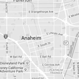


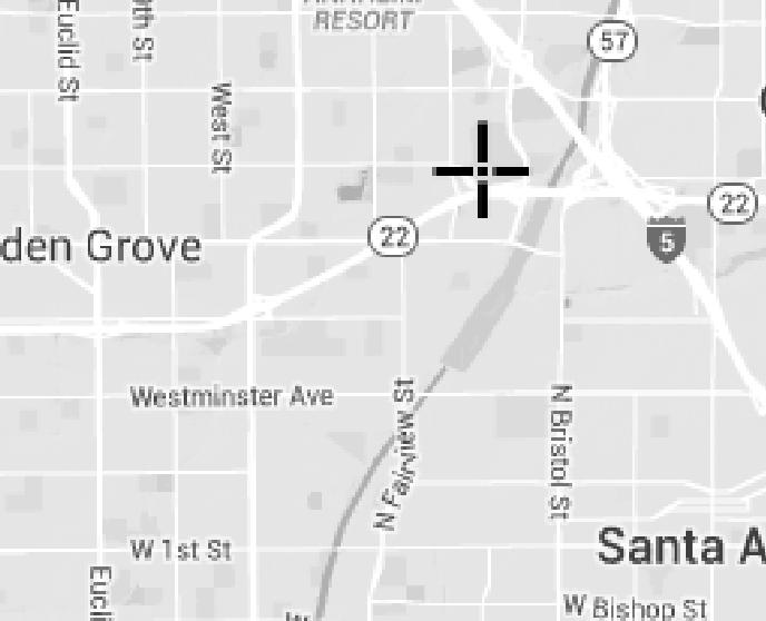


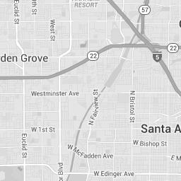

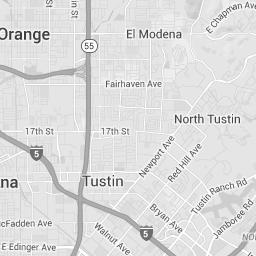
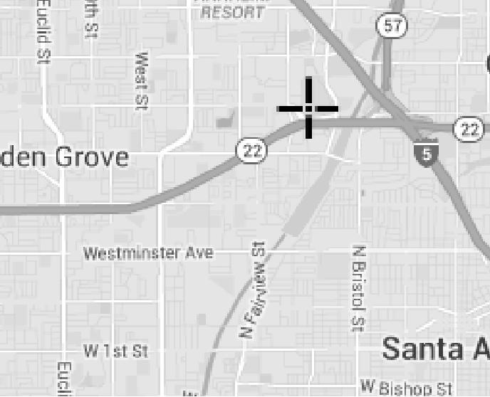

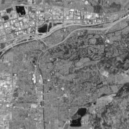

172


173
The Ocean Begins at Your Front Door
 The Ocean Begins at Your Front Door Follow these simple steps to help reduce water pollution: Household Activities Do not rinse spills with water. Use dry cleanup methods such as applying cat litter or
The Orange County Stormwater Program
 The Orange County Stormwater Program 1 Water Resources are Crucial to Orange County Water provides recreation for Orange County residents. It attracts tourists, boosting the local economy. It is home to
City of Aliso Viejo Stormwater Program 2017 ANNUAL WATER QUALITY MANAGEMENT PLAN FOR HOMEOWNER ASSOCIATIONS AND PROPERTY MANAGEMENT COMPANIES
 City of Aliso Viejo Stormwater Program 2017 ANNUAL WATER QUALITY MANAGEMENT PLAN FOR HOMEOWNER ASSOCIATIONS AND PROPERTY MANAGEMENT COMPANIES ANNUAL SUBMITTAL FORM DEADLINE: 5:00 PM ON FEBRUARY 15, 2017
The effects of pollution. What is stormwater runoff? Why is stormwater runoff a problem?
 What is stormwater runoff? Stormwater runoff occurs when precipitation from rain or snowmelt flows over the ground. Impervious surfaces like driveways, sidewalks, and streets prevent stormwater from naturally
Background / Regulatory Requirements
 Chapter 2 Background / Regulatory Requirements This Chapter summarizes the impacts of development on stormwater quality and quantity and explains the postconstruction stormwater control requirements for
How Your Food Service Facility Can Prevent Stormwater Pollution
 Tips for a Cleaner Bay How Your Food Service Facility Can Prevent Stormwater Pollution alameda county You C an Pre vent Water Pollution! Storm drains flow directly into creeks and the Bay without any treatment.
The Clean Water Act: Phase I
 Nearly 40 percent of all surveyed bodies of water in the U.S. do not meet the Environmental Protection Agency s (EPA s) water quality standards because of untreated polluted runoff that is often discharged
F2. Vehicle and Heavy Equipment Repair and Maintenance
 F2. Vehicle and Heavy Equipment Repair and Maintenance Commercial / Industrial / Institutional & Municipal Pollution Prevention Goal: Prevent or reduce the risk of discharge of pollutants to stormwater
Hazardous Waste Management
 Objectives EC SE TC WE NS WM Erosion Control Sediment Control Tracking Control Wind Erosion Control Non-Stormwater Management Control Waste Management and Materials Pollution Control Legend: Primary Objective
Parking Area Maintenance
 Description Parking lots can contribute a number of substances, such as trash, suspended solids, hydrocarbons, oil and grease, and heavy metals that can enter receiving waters through stormwater runoff
WATER QUALITY MANAGEMENT PLAN PROCEDURES
 PUBLIC WORKS DEPARTMENT DEVELOPMENT SERVICES DIVISION SUBDIVISION SERVICES SECTION City Hall East 200 S. Anaheim Boulevard. 2 nd Floor Anaheim, California 92805 www.anaheim.net/publicworks WATER QUALITY
Ordinance amending the San Francisco Public Works Code by adding Article 4.2,
 FILE NO. ORDINANCE NO. 1 [Stormwater Management.] Ordinance amending the San Francisco Public Works Code by adding Article., sections., requiring the development and maintenance of stormwater management
Water in New Orleans. Jennifer Roberts. Sewerage & Water Board of New Orleans
 Water in New Orleans Jennifer Roberts Sewerage & Water Board of New Orleans Restoring and Protecting Water Quality, whose job is it? Water Quality What is Water Quality (WQ) What is lawful? How is WQ regulated?
STORMWATER MANAGEMENT PROGRAM. Table of Contents
 STORMWATER MANAGEMENT PROGRAM Yakima Valley College March 1st, 0 1 0 1 Table of Contents INTRODUCTION... PROGRAM COMPONENTS... S.D.1: PUBLIC EDUCATION AND OUTREACH... Label Storm Drain Inlets:... Public
Vehicle Service Facilities
 Vehicle Service Facilities B e s t M a n a g e m e n t P r a c t i c e s These guidelines cover the following topics: General Pollution Prevention Practices and Good Housekeeping Outdoor Storage l Waste
MS4 Programs: Quality, the Other Stormwater Q. Dan Bounds, PE, D.WRE IAFSM March 9, 2017
 MS4 Programs: Quality, the Other Stormwater Q Dan Bounds, PE, D.WRE IAFSM March 9, 2017 MS4 Rule and Regulations MS4 Municipal Separate Storm Sewer System A conveyance or system of conveyances (catch basins,
6.1 Introduction to Wastewater Issues
 Section 6: Water Pollution This Section will help you: Understand if you generate industrial wastewater; Understand where your wastewater goes; Make sure you meet requirements for floor drains; Properly
Infiltration Guidelines
 Appendix E Infiltration Guidelines As a stormwater management method, infiltration means retaining or detaining water within soils to reduce runoff. Infiltration can be a cost-effective method to manage
You re the Solution to Water Pollution!
 You re the Solution to Water Pollution! Storm Drains Did you know that stormdrains deliver surface water run-off directly to the nearest pond or creek, and eventually to the Bay? Major Pollutants: Soil
Storm Water Pollution Prevention Plan. Wastewater Treatment Facility and Streets & Parks Facility. Village of Fox River Grove, Illinois
 Storm Water Pollution Prevention Plan Wastewater Treatment Facility and Streets & Parks Facility Village of Fox River Grove, Illinois Village of Fox River Grove, Illinois Storm Water Pollution Prevention
Paraprofessional Training Session 1
 Paraprofessional Training Session 1 Part 2: Stormwater Basics November 26, 2012 Rutgers University, Cook Campus Christopher C. Obropta, Ph.D., P.E. Extension Specialist in Water Resources Associate Professor
STORMWATER RUNOFF AND WATER QUALITY IMPACT REVIEW
 SUBCHAPTER 8 STORMWATER RUNOFF AND WATER QUALITY IMPACT REVIEW 7:45-8.1 Purpose and scope of review Except for those projects expressly exempted by this chapter or waived by the Commission, the Commission
Arlington s New Stormwater Management Ordinance. Informational Meeting May 28, 2014
 Arlington s New Stormwater Management Ordinance Informational Meeting May 28, 2014 Outline Overview Plan submission and review P2 plan/implementation Construction inspection SWMF construction Landscape
APPENDIX G Fire BMPs
 APPENDIX G Fire BMPs BEST MANAGEMENT PRACTICES Plan for URBAN RUNOFF MANAGEMENT PARTICIPATING RIVERSIDE COUNTY FIRE FIGHTING AGENCIES City of Corona Fire Department City of Hemet Fire Department City of
Clean water. From nature.
 Clean water. From nature. Natural Treatment System Save water. Do your part. Did you know that over watering or a broken sprinkler on your property can contribute to ocean pollution? Excess watering creates
Stormwater Pollution Prevention Plan (SWPPP) For Single Family Residential Construction within a larger plan of development
 For Single Family Residential Construction within a larger plan of development") COUNTY OF ALBEMARLE Department of Community Development 401 McIntire Road, North Wing Charlottesville, Virginia 22902-4596 Tel. (434) 296-5832 Fax (434) 972-4126 Stormwater Pollution Prevention Plan (SWPPP)
COUNTY OF ALBEMARLE Department of Community Development 401 McIntire Road, North Wing Charlottesville, Virginia 22902-4596 Tel. (434) 296-5832 Fax (434) 972-4126 Stormwater Pollution Prevention Plan (SWPPP)
TECHNICAL GUIDANCE DOCUMENT APPENDICES
 XIV.4. Harvest and Use BMP Fact Sheets (HU) HU-1: Above-Ground Cisterns Cisterns are large rain barrels. While rain barrels are less than 100 gallons, cisterns range from 100 to more than 10,000 gallons
Stormwater Quality Extended Detention Basin Operation and Maintenance (O&M) Manual. for: Located at: Prepared for: Prepared by:
 Manual. for: Located at: Prepared for: Prepared by:") Stormwater Quality Extended Detention Basin Operation and Maintenance (O&M) Manual for: Insert Development Name Located at: Insert Address Prepared for: Insert Property Owner Name, Address, and Phone Number
Stormwater Quality Extended Detention Basin Operation and Maintenance (O&M) Manual for: Insert Development Name Located at: Insert Address Prepared for: Insert Property Owner Name, Address, and Phone Number
City: Stormwaterville Zip Code: County: Addison. City: Stormwaterville Zip Code: County: Addison
 NOTICE OF INTENT TO USE GENERIC PERMIT FOR DISCHARGE OF STORMWATER FROM PHASE II MUNICIPAL SEPARATE STORM SEWER SYSTEMS (RULE 62-621.300(7)(b), F.A.C.) For FDEP Internal Use Only Permit : FLR INSTRUCTIONS:
SUBSURFACE INFILTRATION SYSTEM DESCRIPTION. Alternative Names: Sump, Drywell, Infiltration Trench, Infiltration Galleries, Leach Fields
 4.1-d SUBSURFACE INFILTRATION SYSTEM Alternative Names: Sump, Drywell, Infiltration Trench, Infiltration Galleries, Leach Fields BMP DESIGN APPROACH Pollutant Source Control Hydrologic Source Control Stormwater
Orange County Fertilizer Application Education Course for Citizens
 Orange County Fertilizer Application Education Course for Citizens Thanks for taking the time to learn how to keep Central Florida beautiful while protecting our water quality! Why is Orange County Requiring
POLLUTION PREVENTION AFTER CONSTRUCTION
 POLLUTION PREVENTION AFTER CONSTRUCTION..CHAPTER.. 10 This chapter describes the pollution prevention measures to be taken once the site has been permanently and finally stabilized and no additional construction
Streamlines V2, n2 (May 1997) A Newsletter for North Carolina Water Supply Watershed Administrators
 A Newsletter for North Carolina Water Supply Watershed Administrators") Page 1 of 5 STREAMLINES A Newsletter for North Carolina Water Supply Watershed Administrators Volume 2, Number 2 May 1997 Non-Point Source (NPS) Pollution This issue of Streamlines provides basic information
Page 1 of 5 STREAMLINES A Newsletter for North Carolina Water Supply Watershed Administrators Volume 2, Number 2 May 1997 Non-Point Source (NPS) Pollution This issue of Streamlines provides basic information
Understanding Stormwater Pollution Prevention Plans (SWPPPs) (SWPPPS)
 (SWPPPS)") Understanding Stormwater Pollution Prevention Plans (SWPPPs) (SWPPPS) Definitions SWPPP: Storm Water Pollution Prevention Plan BMP: Best Management Practice(s) to control pollution IDNR: Iowa Department
Understanding Stormwater Pollution Prevention Plans (SWPPPs) (SWPPPS) Definitions SWPPP: Storm Water Pollution Prevention Plan BMP: Best Management Practice(s) to control pollution IDNR: Iowa Department
Texas Pollutant Discharge Elimination System Industrial Storm Water Permit TXR Storm Water Pollution Prevention Plan Worksheet Instructions
 Texas Pollutant Discharge Elimination System Industrial Storm Water Permit TXR050000 Storm Water Pollution Prevention Plan Worksheet Instructions The TCEQ Small Business and Local Government Assistance
COUNTY OF LOS ANGELES DEPARTMENT OF PUBLIC WORKS BUILDING AND SAFETY DIVISION - DRAINAGE & GRADING SECTION
 COUNTY OF LOS ANGELES DEPARTMENT OF PUBLIC WORKS BUILDING AND SAFETY DIVISION - DRAINAGE & GRADING SECTION STANDARD URBAN STORMWATER MITIGATION PLAN (SUSMP) REVIEW SHEET Urban and storm water runoff is
Clean Water is Everyone s Business. A commercial & industrial property owner s guide to improving Lake Tahoe s clarity
 Clean Water is Everyone s Business A commercial & industrial property owner s guide to improving Lake Tahoe s clarity this informational guide will help you understand the tahoe regional planning agency
Erosion & Sedimentation Control Policy
 Issue Date 10/22/2010 Page 1 of 8 Erosion & Sedimentation Control Policy Introduction: Soil erosion is the removal of soil by water, wind, ice or gravity and sediment deposition occurs when the rate of
Green Real Estate. NSCC - RES 130 Online. Module 3 Sustainable Sites & Water Cate O dahl, Instructor. Learning Objectives
 Green Real Estate NSCC - RES 130 Online Module 3 Sustainable Sites & Water Cate O dahl, Instructor Sustainable Sites & Water Conservation Learning Objectives Relationship of the Building to Water Issues
INDUSTRIAL STORMWATER BMPS. Improving local water quality one step at time
 INDUSTRIAL STORMWATER BMPS Improving local water quality one step at time Webinar will begin at 1:00 p.m. CST. December 4, 2009 Webinar Logistics Can t hear? If it s not the computer volume, then may access
CITY OF ENCINITAS STORMWATER INTAKE FORM AND PRIORITY DEVELOPMENT PROJECT STORMWATER QUALITY MANAGEMENT PLAN (SWQMP)
") CITY OF ENCINITAS STORMWATER INTAKE FORM AND PRIORITY DEVELOPMENT PROJECT STORMWATER QUALITY MANAGEMENT PLAN (SWQMP) FOR: [PROJECT NAME] [APPLICATION/PERMIT NUMBER(S)] [SITE ADDRESS] [ENCINITAS, CA 92024]
CITY OF ENCINITAS STORMWATER INTAKE FORM AND PRIORITY DEVELOPMENT PROJECT STORMWATER QUALITY MANAGEMENT PLAN (SWQMP) FOR: [PROJECT NAME] [APPLICATION/PERMIT NUMBER(S)] [SITE ADDRESS] [ENCINITAS, CA 92024]
GUIDELINES FOR STORMWATER BACTERIA REDUCTIONS THROUGH BMP IMPLEMENTATION NY/NJ HARBOR TMDL DEVELOPMENT
 GUIDELINES FOR STORMWATER BACTERIA REDUCTIONS THROUGH BMP IMPLEMENTATION NY/NJ HARBOR TMDL DEVELOPMENT Elevated bacteria in stormwater runoff in urban areas are well documented by many researchers. Monitoring
Old Dominion University MS4 Program Plan
 OFFICE OF ENVIRONMENTAL HEALTH AND SAFETY 5255 Hampton Blvd. Spong Hall, suite 2501 Norfolk, Virginia 23529 Phone: (757) 683-4495 Fax: (757) 683-6025 Occupational Safety & Health Environmental Health Laboratory
StormwaterWise Landscapes: Pervious Surfaces Specifications
 StormwaterWise Landscapes: Pervious Surfaces Specifications Purpose & Benefits Stormwater runoff reduction High pollutant removal Control localized drainage problems Attractive alternative for walkways
Chapter 21 Stormwater Management Bylaw
 Chapter 21 Stormwater Management Bylaw SECTION 1. PURPOSE The purpose of this Bylaw is to: implement the requirements of the National Pollutant Discharge Elimination System (NPDES) General Permit for Storm
The Village of Wellington NPDES Guidance/Reference Document
 The Village of Wellington NPDES Guidance/Reference Document The following Permit Compliance Guidance/Reference Document has been compiled to assist the copermittee in fulfilling the requirements of the
Water Assessment and Audit. Congratulations on completing Step 1 by forming your Green Team!
 School Name: Date: Conducted By: Congratulations on completing Step 1 by forming your Green Team! Step 2: Assess Complete this to learn more about the current water conservation and quality practices at
What is a stormwater utility fee?
 What is a stormwater utility fee? A stormwater utility fee is similar to a water or sewer utility fee. In essence, customers pay a fee to convey stormwater from their properties. The City of Goodlettsville
RESTAURANTS AND FOOD OUTLETS
 Best Practice Guidelines for Stormwater Pollution Prevention RESTAURANTS AND FOOD OUTLETS MANAGING WASH WATER I Contents SECTION PAGE Introduction 2 What you need to know 3 Stormwater and wastewater -
STORMWATER POLLUTION PREVENTION PLAN
 STORMWATER POLLUTION PREVENTION PLAN TOWN OF WHITE BEAR, MINNESOTA Date: May 31, 2006 Project No. 13597.000 White Bear Township Storm Water Pollution Prevention Plan BMPS Following are the BMPs included
S.O.P. No. HMD
 Page: 1 of 9 PURPOSE: To establish (SOP) for submission requirements, review process and approval of applications for Non-vehicular Access Permits for the purpose of connection or discharge to any MassDOT
Non-point source pollution now accounts for over 75% of Pennsylvania s total water pollution
 2. Non-point Source Pollution Living on the Landscape and How We Affect Our Shared Water Resources by John Jose, Watershed Specialist, Pike County Conservation District Water is the most critical resource
BMPs. Pressure Washing. Surface Cleaning. for. and. Public Works - Stormwater Division City of Lawrence, KS
 BMPs for Pressure Washing and Surface Cleaning Public Works - Stormwater Division City of Lawrence, KS November, 2004 INTRODUCTION This booklet describes the requirements for the disposal of waste and
A Case for the Design and Modeling of BMP Infiltration and LID Techniques. By: Bob Murdock
 A Case for the Design and Modeling of BMP Infiltration and LID Techniques 2009 IAFSM Annual Conference 2009 IAFSM Annual Conference By: Bob Murdock Presentation Outline 1. Runoff Reduction (RR) and Low
2011 Guidance Manual for Development Stormwater Quality Control Measures
 CITY OF MODESTO STORMWATER MANAGEMENT PROGRAM 2011 Guidance Manual for Development Stormwater Quality Control Measures Prepared for NPDES Permit No. CAS083526; Order R5-2008-0092 This page intentionally
INTRODUCTION TO HOBBY FARMING AND WATER QUALITY
 SECTION ONE INTRODUCTION TO HOBBY FARMING AND WATER QUALITY This is a handbook for owners of Hobby Farms - small scale farms operated primarily as a residential lifestyle - to provide their owners with
Pollution Prevention/Good Housekeeping for Municipal Facilities
 Pollution Prevention/Good Housekeeping for Municipal Facilities Wednesday, March 17, 2010 8:30 am-9:30am Perrysburg Township Ann-Drea Hensley Stormwater Intern Toledo Metropolitan Area Council of Governments
Review of State and Federal Stormwater Regulations November 2007
 Review of State and Federal Stormwater Regulations November 2007 By: James T. Spaulding, PE, CPESC Joseph M. Ducharme, Jr., PE TTG ENVIRONMENTAL CONSULTANTS, LLC 27 LOCKE ROAD, CONCORD, NH 03301-5301 TELEPHONE:
Stormwater Management Program Plan (SWMPP) NPDES Permit ALR Revised May 31, Prepared By:
 NPDES Permit ALR Revised May 31, Prepared By:") City of Fultondale 1210 Walker Chapel Road P.O. Box 699 Fultondale, Al 35068 Stormwater Management Program Plan () Revised May 31, 2017 Prepared By: 7110 University Court, Montgomery, Alabama 36117 (THIS
City of Fultondale 1210 Walker Chapel Road P.O. Box 699 Fultondale, Al 35068 Stormwater Management Program Plan () Revised May 31, 2017 Prepared By: 7110 University Court, Montgomery, Alabama 36117 (THIS
Decatur, Georgia Stormwater Management Policy Guidelines. DRAFT November 5, 2014
 Decatur, Georgia Stormwater Management Policy Guidelines Stormwater Management Policy Guidelines Decatur, Georgia STORMWATER MANAGEMENT POLICY GUIDELINES 1.0 Introduction... 3 2.0 Determining Predevelopment
Rhode Island Stormwater Design and Installation Standards Manual-- Final Draft: Public Informational Session May 26, 2010 at CCRI
 Rhode Island Stormwater Design and Installation Standards Manual-- Final Draft: Public Informational Session May 26, 2010 at CCRI Questions and Answers Chapter 3 Q1. Will there be a provision for revising
PERVIOUS PAVEMENT. Alternative Names: Permeable Pavement, Porous Concrete, Porous Pavers
 4.1-a PERVIOUS PAVEMENT Alternative Names: Permeable Pavement, Porous Concrete, Porous Pavers DESCRIPTION Pervious pavement is any system comprised of a load bearing surface that allows for movement of
Stormwater Programs. BIA Meeting June 5, Jason Uhley
 Stormwater Programs BIA Meeting June 5, 2014 Jason Uhley Chief of Watershed Protection Riverside County Flood Control and Water Conservation District Presentation Outline Clean Water Act Stormwater Program
DRAINAGE AREA MANAGEMENT PLAN (DAMP)
") DRAINAGE AREA MANAGEMENT PLAN (DAMP) Exhibit 7.II Model Water Quality Management Plan (WQMP) A COOPERATIVE PROJECT OF THE COUNTY OF ORANGE, THE CITIES OF ORANGE COUNTY AND THE ORANGE COUNTY FLOOD CONTROL
DRAINAGE AREA MANAGEMENT PLAN (DAMP) Exhibit 7.II Model Water Quality Management Plan (WQMP) A COOPERATIVE PROJECT OF THE COUNTY OF ORANGE, THE CITIES OF ORANGE COUNTY AND THE ORANGE COUNTY FLOOD CONTROL
EXAMPLE Stormwater Management Plans w/ CSS BMP Sizing Calculator (v2.1)
") 525 Golden Gate Avenue, 11th Floor San Francisco, CA 94102 EXAMPLE Stormwater Management Plans w/ CSS BMP Sizing Calculator (v2.1) The following example Stormwater Management Plans (SMPs) are provided
525 Golden Gate Avenue, 11th Floor San Francisco, CA 94102 EXAMPLE Stormwater Management Plans w/ CSS BMP Sizing Calculator (v2.1) The following example Stormwater Management Plans (SMPs) are provided
WATER QUALITY MANAGEMENT PLAN FOR URBAN RUNOFF
 Public Review Draft April 30, 2004 WATER QUALITY MANAGEMENT PLAN FOR URBAN RUNOFF Santa Ana River Region Santa Margarita River Region Riverside County Water Quality Management Plan Public Review Draft
4.8. Subsurface Infiltration
 4.8. Subsurface Infiltration Subsurface infiltration systems are designed to provide temporary below grade storage infiltration of storm water as it infiltrates into the ground. Dry wells, infiltration
Preliminary Drainage Analysis
 Preliminary Drainage Analysis Tanimura and Antle Employee Housing Town of Spreckels County of Monterey, California LIB150205 May 29, 2015 Prepared For: Tanimura and Antle Produce Prepared By: 9699 Blue
MARCH 2013 TO MARCH 2014 (YEAR 11) REPORTING PERIOD VILLAGE OF SKOKIE, ILLINOIS
 REPORTING PERIOD VILLAGE OF SKOKIE, ILLINOIS") ILLINOIS ENVIRONMENTAL PROTECTION AGENCY ANNUAL FACILITY INSPECTION REPORT NPDES PERMIT FOR STORM WATER DISCHARGES FROM MUNICIPAL SEPARATE STORM SEWER SYSTEMS (MS4) MARCH 2013 TO MARCH 2014 (YEAR 11) REPORTING
ILLINOIS ENVIRONMENTAL PROTECTION AGENCY ANNUAL FACILITY INSPECTION REPORT NPDES PERMIT FOR STORM WATER DISCHARGES FROM MUNICIPAL SEPARATE STORM SEWER SYSTEMS (MS4) MARCH 2013 TO MARCH 2014 (YEAR 11) REPORTING
STORMWATER POLLUTION PREVENTION PLAN (SWP3)
") City of Moore, Oklahoma Community Development Department 301 North Broadway Moore, Oklahoma 73160 STORMWATER POLLUTION PREVENTION PLAN (SWP3) The SWP3 is a written narrative describing the site, potential
City of Moore, Oklahoma Community Development Department 301 North Broadway Moore, Oklahoma 73160 STORMWATER POLLUTION PREVENTION PLAN (SWP3) The SWP3 is a written narrative describing the site, potential
ES Cleaning/Washing - Aircraft, Vehicles and Equipment Document Identification Number Date: March 15, 2018
 ES-301-1.02 Cleaning/Washing - Aircraft, Vehicles and Equipment Document Identification Number ES-301-1.02 Date: March 15, 2018 Document Owner: Keith Pass 1) Activity Description: The following guideline
Chapter 3 BMPs for Homeowners
 BMPs for Homeowners Actions taken each day in and around homes have a profound effect on surface water quality and fish habitat in this region. Stormwater goes directly to lakes, streams and to Puget Sound.
Extended Detention Basin Maintenance Plan for [[== Insert Project Name ==]]
![Extended Detention Basin Maintenance Plan for [[== Insert Project Name ==]]](/thumbs/72/68075589.jpg "Extended Detention Basin Maintenance Plan for [[== Insert Project Name ==]]") Extended Detention Basin Plan for [[== Insert Project Name ==]] [[== Insert Date =]] Project Address and Cross Streets Assessor s Parcel No.: Property Owner: Phone No.: Designated Contact: Phone No.: Extended
Extended Detention Basin Plan for [[== Insert Project Name ==]] [[== Insert Date =]] Project Address and Cross Streets Assessor s Parcel No.: Property Owner: Phone No.: Designated Contact: Phone No.: Extended
Preventing Storm Drain Pollution
 Preventing Storm Drain Pollution Guidelines for Commercial and Light Industrial Facilities For more information about Stormwater Pollution Prevention 1-866-WATERSHED www.mywatershedwatch.org Santa Clara
Concrete Waste Management
 Categories EC SE TC WE NS WM Erosion Control Sediment Control Tracking Control Wind Erosion Control Non-Stormwater Management Control Waste Management and Materials Pollution Control Legend: Primary Category
Project Name: Add a unique name that appropriately identifies the submission
 PTAPP Online Municipal Tracking Tool Instructions Project Name: Add a unique name that appropriately identifies the submission Municipal Project: Check this box if the project is part of municipal efforts
4.8. Subsurface Infiltration
 4.8. Subsurface Infiltration Subsurface infiltration systems are designed to provide temporary below grade storage infiltration of stormwater as it infiltrates into the ground. Dry wells, infiltration
CHAPTER 10 SOURCE CONTROL
 CHAPTER 10 SOURCE CONTROL Chapter Organization 10.1 Purpose... 10-1 10.1.1 Goals and Objectives of Source Control... 10-1 10.2 Applicability... 10-1 10.2.1 Site Uses That Require Source Control... 10-2
GI BMP Training Program Review Worksheets
 GI BMP Training Program Review Worksheets 2/7/2013 Version 1 ANSWER KEY Instructions: Use the worksheets as a guide to review key learning points and information provided during the training program. Depending
Sherman Library Maintenance Handbook for Porous Asphalt
 Sherman Library Maintenance Handbook for Porous Asphalt Porous asphalt systems are an effective means of stormwater management. Unlike traditional pavements, rainfall drains through the pavement surface
COUNTY OF NEVADA COMMUNITY DEVELOPMENT AGENCY NEVADA COUNTY CDA GUIDELINES FOR ASH AND BURN DEBRIS CLEAN UP AND REMOVAL AFTER A FIRE
 COUNTY OF NEVADA COMMUNITY DEVELOPMENT AGENCY Environmental Health Department 950 MAIDU AVENUE, SUITE 170 NEVADA CITY, CA 95959-8617 (530) 265-1222 FAX (530) 265-9853 http://mynevadacounty.com Amy Irani,
STORMWATER AND EROSION CONTROL PERMIT
 STORMWATER MANAGEMENT AND EROSION CONTROL PERMIT INSTRUCTIONS AND INFORMATION Any project that involves the disturbance of ANY quantity of land requires the applicant to receive approval for the project
Boise City Public Works General Drainage Plan Review Requirements Checklist
 Boise City Public Works General Drainage Plan Review Requirements Checklist Development Name Bldg. Permit # Drainage Reviewer Site Address Initial Review Date ODI Number Designer Company Name Treated Acres
STATE OF FLORIDA DEPARTMENT OF ENVIRONMENTAL PROTECTION GENERIC PERMIT FOR DISCHARGE OF STORMWATER FROM PHASE II
 STATE OF FLORIDA DEPARTMENT OF ENVIRONMENTAL PROTECTION GENERIC PERMIT FOR DISCHARGE OF STORMWATER FROM PHASE II MUNICIPAL SEPARATE STORM SEWER SYSTEMS May 1, 2003 1 Generic Permit for Discharge of Stormwater
UMD Storm Water Program Construction Requirements. Greg Archer, MBA Environmental Compliance Specialist
 UMD Storm Water Program Construction Requirements Greg Archer, MBA Environmental Compliance Specialist Phase 2 Regulatory Overview Dec. 1999 EPA issues Phase 2 Federal Register Municipalities (MS4) from
Tips for a Cleaner Bay
 Tips for a Cleaner Bay h o w y o u r s c h o o l c a n P r e v e n t s t o r m w a t e r p o l l u t i o n These guidelines cover the following topics: General Stormwater Pollution Prevention Practices
Municipal Stormwater Ordinances Summary Table
 APPENDIX F Municipal Ordinances Summary Table Municipality Abington Bryn Athyn Borough Hatboro Borough Ordinance, SALDO Runoff equals pre post Erosion Sediment Control Water Quality Requirements Any which
INSPECTION, MAINTENANCE AND HOUSEKEEPING PLAN
 INSPECTION, MAINTENANCE AND HOUSEKEEPING PLAN Bates College 55 & 65 Campus Avenue Housing Lewiston, Maine Introduction The following plan outlines the anticipated inspection and maintenance procedures
BRADLEY UNIVERSITY. The Performance and Sustainability of Permeable Pavement Progress Report on the Work Performed Under IAPA Scholarship
 BRADLEY UNIVERSITY The Performance and Sustainability of Permeable Pavement Progress Report on the Work Performed Under IAPA Scholarship Anne Riemann 12/19/2016 1 INTRODUCTION Permeable pavement is an
VIRGINIA POLLUTION ABATEMENT (VPA) PERMIT APPLICATION. FORM B - ANIMAL FEEDING OPERATIONS (AFOs)
 PERMIT APPLICATION. FORM B - ANIMAL FEEDING OPERATIONS (AFOs)") VIRGINIA POLLUTION ABATEMENT (VPA) PERMIT APPLICATION FORM B - ANIMAL FEEDING OPERATIONS (AFOs) Department of Environmental Quality Rev. 02-2013 VIRGINIA POLLUTION ABATEMENT (VPA) PERMIT APPLICATION FORM
VIRGINIA POLLUTION ABATEMENT (VPA) PERMIT APPLICATION FORM B - ANIMAL FEEDING OPERATIONS (AFOs) Department of Environmental Quality Rev. 02-2013 VIRGINIA POLLUTION ABATEMENT (VPA) PERMIT APPLICATION FORM
COON CREEK WATERSHED DISTRICT PERMIT REVIEW. Spring Lake Park Schools Westwood Middle School st Avenue NE, Spring Lake Park, MN 55432
 PAN 16-112, Westwood Middle School, Page 1 of 6 COON CREEK WATERSHED DISTRICT PERMIT REVIEW MEETING DATE: August 22, 2016 AGENDA NUMBER: 10 FILE NUMBER: 16-112 ITEM: Westwood Middle School RECOMMENDATION:
SECTION 3 DRAINAGE. 3-1 General. 3-2 Drainage Ordinances and Legal Requirements
 SECTION 3 DRAINAGE 3-1 General All Drainage plans for proposed development shall be prepared by a Professional Engineer registered in Virginia, except as noted below. Further, their seal and signature
ATTACHMENT 4 Section Project Status Quarterly Report - Dec 31, 2015 Measure V - Clean Beaches and Ocean Parcel Tax
 ATTACHMENT 4 Section 3.0 - Project Status Quarterly Report - Dec 31, 2015 Completed Projects Description Bicknell Avenue Green Street Pier Storm Drain Improvement Pier Water Quality Improvement Permeable
Final Water Quality Management Plan
 Final Water Quality Management Plan For: Woodspring Suites Redlands DEVELOPMENT FILE: CUP #1076; PR #1329 1700 Orange Tree Lane Redlands, CA 92374 Prepared for: Woodspring Suites Redlands San Bernardino
Occupational Safety & Health Environmental Health Laboratory Safety Industrial Hygiene Radiation Safety Hazardous Waste Pollution Prevention
 OFFICE OF ENVIRONMENTAL HEALTH AND SAFETY 5255 Hampton Blvd. Spong Hall, suite 2501 Norfolk, Virginia 23529 Phone: (757) 683-4495 Fax: (757) 683-6025 Occupational Safety & Health Environmental Health Laboratory
New Draft Model BMP Design Manual for San Diego Region
 New Draft Model BMP Design Manual for San Diego Region Public Input 2013 Storm Water Permit June 10, 2014 & June 11, 2014 1 Welcome Sign-In Refreshments Sponsor Break Q&A and Input 2 Outline of Presentation
BMP #: Infiltration Basin
 Structural BMP Criteria BMP #: Infiltration Basin An Infiltration Basin is a shallow impoundment that stores and infiltrates runoff over a level, subtle, uncompacted, (preferably undisturbed area) with
STORM WATER PLAN (SWP) GUIDANCE TEMPLATE
 GUIDANCE TEMPLATE") STORM WATER PLAN (SWP) GUIDANCE TEMPLATE Name of Facility: Address: Phone Number: Date: INTRODUCTION This Storm Water Plan (SWP) is written in accordance with the State of Delaware Regulations Governing
STORM WATER PLAN (SWP) GUIDANCE TEMPLATE Name of Facility: Address: Phone Number: Date: INTRODUCTION This Storm Water Plan (SWP) is written in accordance with the State of Delaware Regulations Governing
CITY OF ASTORIA PUBLIC WORKS ENGINEERING DIVISION ENGINEERING DESIGN STANDARDS FOR IN-FILL DEVELOPMENT
 CITY OF ASTORIA PUBLIC WORKS ENGINEERING DIVISION ENGINEERING DESIGN STANDARDS FOR IN-FILL DEVELOPMENT Adopted by City Council: May 21, 2007 X:\General Eng\DESIGN STANDARDS\Engineering Design Standards
3.0 Planning and Submittal Requirements
 October 2003, Revised February 2005 Chapter 3.0, Planning and Submittal Requirements Page 1 3.0 Planning and Submittal Requirements 3.1 Drainage Studies and Drawings The City of Greenwood Village (Village)