HYDROLOGIC-HYDRAULIC STUDY ISABELLA OCEAN RESIDENCES ISLA VERDE, CAROLINA, PR
|
|
|
- Theresa Potter
- 6 years ago
- Views:
Transcription
1
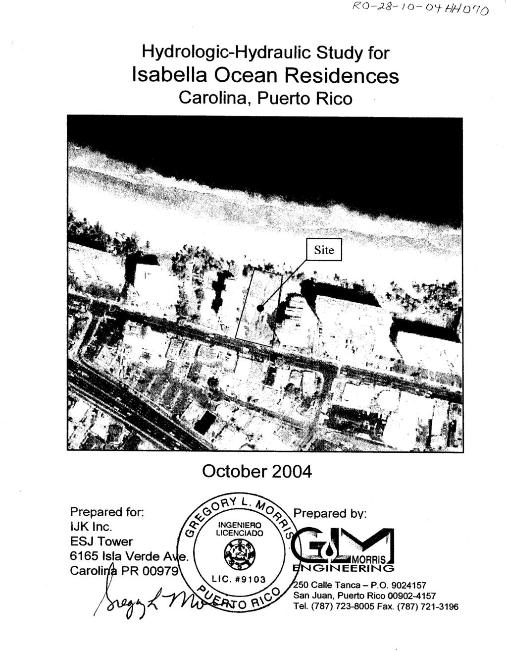
2 HYDROLOGIC-HYDRAULIC STUDY ISABELLA OCEAN RESIDENCES ISLA VERDE, CAROLINA, PR 1 INTRODUCTION 1.1 Project Description and Location Isabella Ocean Residences is a residential development to be constructed on a acre parcel located on Isla Verde Avenue in the municipality of Carolina. Figure 1 shows the project location on the San Juan topographic quadrangle. The project will consist of a multi-story building with common areas, recreational spaces and a multi-level underground parking lot. The site is presently occupied by a single-family residence and a parking lot that will be demolished to develop the residential project. 1.2 Scope and Purpose of Study This document constitutes the hydrologic-hydraulic study for the proposed project. It has been undertaken to determine the required stormwater detention volume for the proposed development to comply with Puerto Rico Planning Board Regulation #3, section 15, which requires that peak site runoff under the proposed condition not exceed the existing condition peak discharge. It also provides the hydraulic dimensions for the stormwater control structure. This report should be used as the basis for civil design of the project. 1.3 Report Limitations and Warnings It shall be the responsibility of the site engineer or the project s geotechnical consultant to adapt the hydraulic design recommendations to the soil and other conditions at the site in any matters concerning slope stability, conflicts with other infrastructure, etc. 1.4 Authorization Mr. Joel Katz, President of IJK Inc., has authorized preparation of this report, in representation of the owner, through an agreement with Gregory Morris Engineering
3 1.5 Personnel Involved in Project The professionals of Gregory Morris Engineering involved in the realization of this study were: Gregory L. Morris P.E. José D. Miranda P.E. The following parties were involved in the project: Designer: LRA Architects - 2 -
4 2 STUDY AREA DESCRIPTION 2.1 Topography and Water Bodies Site elevations range between 2.67 m and 3.24 m (msl). Due to topographic characteristics runoff generated on the site drains superficially toward Isla Verde Avenue and enters the storm sewer system though a curb inlet adjacent to the site s existing entrance. No offsite runoff enters the property. There are no water bodies or sinkholes on the site, but the Atlantic Ocean borders the site on the north. Figure 2 shows the topographic features of the site. 2.2 Prior Studies The Isabella Ocean Residences site is classified as Zone -X in the FEMA Flood Insurance Rate Map (FIRM). A copy of the FEMA Floodway map (Panel 52, revised June 2, 1999) is presented as Figure 3. The project area is not classified as floodable by the Puerto Rico Planning Board Flood Zoning Map (see Figure 4). The regulatory flood elevation presented on the maps is 2.40 m-msl due to storm surge. There are no prior hydrologic-hydraulic studies for the site. 2.3 Field Data This study uses topographic survey data provided by Surveyor Eugenio López Encarnación. The survey was performed during the month of June 2003 and is referenced to mean sea level. A copy of the topographic data is included in the back pocket of this report. 2.4 Field Visit The site was visited during the month of November, Observed conditions are summarized below. The site consists of two properties. The east property consists of a single residence with significant green area. The west property is a paved parking lot. There is no storm sewer system on the site. The ground slopes to the south and runoff generated at the site drains superficially toward Isla Verde Avenue. This runoff reaches the Isla Verde Avenue storm sewer system through a curb inlet located close to the site s entrance
5 3 STUDY APPROACH 3.1 Conceptualization of the Hydraulic System The hydraulic system for the existing condition was conceptualized as one on-site basin (representing the project site) draining to a node (representing the curb inlet at Isla Verde Avenue) where the peak discharge produced by the basin was determined. For the post-development condition, land use parameters and drainage patterns were altered to account for the proposed site plan and change in hydrologic parameters at the site, plus the proposed detention structures. 3.2 Study Approach and Methodology A detention analysis requires the generation of storm hydrographs showing the variation of runoff over time. The runoff hydrographs in this analysis were generated using the Soil Conservation Service unit hydrograph methodology as implemented in the ICPR model. Detention volume temporarily stores runoff and releases it more slowly through a hydraulic structure. Sizes of the required storage and hydraulic configuration of the outlet structure were determined by hydrologic and hydraulic modeling, comparing existing and proposed condition runoff hydrographs at the point of analysis. The study has been performed using the ICPR unsteady flow hydrologic-hydraulic modeling system (Streamline Technologies v3.0, Winter Park, Florida). The ICPR model dynamically routes stormwater through open channels, closed conduits and detention ponds. The program s solution algorithm allows it to simulate a variety of complex conveyance systems. Each node in ICPR represents a control volume. Change in storage for each node is calculated based on the difference between inflows and outflows at each time step during the simulation period. The change in storage is used to determine elevations at each node at the end of each time step. Flow through each link is calculated from the known elevations at each end of the link and the hydraulic properties of the link. The hydrologic and hydraulic analysis was performed to determine the discharge hydrographs for 2-, 10-, and 100- year return intervals storms from the area under existing and proposed land use conditions
6 4 HYDROLOGIC ANALYSIS 4.1 Curve Number and Time of Concentration Soils in the area were not surveyed in the Soil Survey of San Juan Area of Puerto Rico (Boccheciamp, 1977) because it is an urban area. Figure 5 shows a partial reproduction of the soil survey where the project is located. Soil classification was adopted from the geotechnical exploration performed at the site area by Geo- Engineering and site inspection. Soils in the project area consist of beach sands and are in hydrologic class A which indicates they have a low runoff potential. Antecedent Moisture Condition II was used. Table 1 and Table 3 show the Curve Numbers used in this analysis for existing and proposed conditions, respectively. Table 1: Curve Number Calculations for Project Site under Existing Conditions Soil Type Hydrologic Soil Group Land Use Area (m 2 ) Curve Number Tropopsamments A Grass, brush 1, Tropopsamments A Paved Area 2, Weighted Curve Number 88 Table 2: Curve Number Calculations for Drainage Areas under Proposed Conditions Drainage Area Land Use Area (m 2 ) Curve Number Roof 1 Paved Roof 2 Paved Remainder Site Paved/some grass 2, The time of concentration is the time required for a drop of water falling on the most distant point of the watershed to influence discharge at the watershed exit. The time of concentration was calculated using Soil Conservation method (TR-55). For sheet flow calculation the following equation was used: t c = (0.007*n 0.8 *L 0.8 ) / (P 2 0.5*S 0.4 ) where: t c = time of concentration (minutes) n = Manning s roughness coefficient - 5 -
7 L = flow length (ft) P 2 = 2-year, 24-hour rainfall (in) S = slope of hydraulic grade line (land slope, ft/ft) The time of concentration for the entire project site under existing conditions is 5 minutes. Table 3 shows the results of the time of concentration calculations for the three different drainage areas used in the proposed condition model. Table 3: Time of Concentration Calculations for Drainage Areas under Proposed Conditions Drainage Area Time of Concentration (minutes) Roof 1 3 Roof 2 3 Site other than roof Rainfall The study used the 24-hour rainfall depths reported by the US Department of Commerce (1961) in Technical Paper-42, and the Soil Conservation Service Type-II 24- hour rain distribution. The rainfall depths at the project site are shown in Table 4. Table 4: 2-, 10- and 100- year Rainfall Depths (TP-42) at Project Site Return Interval Rainfall Depth 2-years 10-years 100-years 5 inches 7 inches 10 inches 4.3 Results of Hydrologic Analysis The peak discharges in this analysis were computed by the Natural Resources Conservation Service s unit hydrograph methodology with a peaking factor of 484. Table 5 presents peak discharges reaching Isla Verde Avenue for existing and proposed land use conditions, without detention storage
8 Table 5: Existing and Proposed Condition (without detention storage) Peak Discharges Peak Discharge (ft 3 /s) Condition 2-year 10-year 100-year Existing Proposed Verification of Hydrology Peak discharges for basins with areas less than 150 acres were verified using the rational method: Q = C*I*A where: Q = peak discharge (ft 3 /s) C = runoff coefficient I = rainfall intensity (in/hr) A = drainage area (acres) Parameter values were obtained from Normas de Diseño para Sistemas de Alcantarillado Pluvial (Puerto Rico Planning Board, 1975). Table 6 shows the parameters used and results obtained with the Rational Method. Table 6: Parameters used for Hydrology Verification with Rational Method Condition Rainfall Intensity (in/hr) Runoff Coefficient Peak Discharge (ft 3 /s) Existing Proposed Table 7 compares 100-year peak discharges obtained by ICPR and those obtained with the rational method. Based on verification computations, the peak discharges produced by ICPR were accepted as reasonable. Table 7: Verification of Hydrology Results Condition 100-year Peak Discharge (ft 3 /s) ICPR Rational Method Existing Proposed
9 5 HYDRAULIC ANALYSIS Three ICPR models were prepared to study the effects of the proposed project, one for the existing condition and two for the proposed condition. The existing condition model consists of the onsite basin draining into the Isla Verde Avenue curb inlet. Under proposed conditions runoff will drain from the roofs into the proposed detention system, and the rest of the site drains directly into the street. Two different detention structure configurations were analyzed. Figure 6 shows a schematic node-link configuration for existing conditions. Figure 7 and Figure 8 show detention structure Alternative 1 and Alternative 2, respectively. 5.1 Existing Condition Model The existing condition model simulates existing hydrologic conditions on the project site. The model consists of the project site basin discharging into the Isla Verde Avenue curb inlet located in front of the property. Appendix A shows input data and modeling results for the existing condition. 5.2 Proposed Condition Models The purpose of the proposed condition model is to size the detention storage necessary to insure that the post-development discharge downstream the site does not exceed the existing condition discharge. Roof runoff is directed into the detention structure. Figure 9 shows the proposed project layout. The total roof area was divided into two identical drainage areas, each discharging into its own identical detention structure. Each detention structure (for both Alternative 1 and Alternative 2) consists of flow diversion box and detention tank. All discharge generated by the roof should be collected in the flow diversion box. A portion of this flow will discharge through the floor orifice in the flow diversion box and excess flow will pass over the weir and into the detention tank. The total discharge exiting the diversion box and detention tank for each portion of the roof, plus the total discharge exiting the rest of the site, will not exceed the existing condition discharge. The detention structures were modeled with the parameters presented in Section 6.1 of this report. Appendix B and C shows input data and modeling results of the proposed condition model for Alternative 1 and Alternative 2, respectively
10 Table 8 presents the existing and proposed condition discharges produced by the project site. Table 8: Existing and Proposed Conditions Peak Discharge Condition Peak Discharge (ft 3 /s) 2-year 10-year 100-year Existing Proposed Alternative 1 Proposed Alternative
11 6 HYDRAULIC DESIGN RECOMMENDATIONS 6.1 Detention Structure Design Parameters The detention system for the proposed project was modeled as a combination of diversion boxes and detention tanks. The roof will be divided into two halves, each draining into its own detention structure. Runoff from the roof will enter a flow diversion box with and orifice in the floor and a rectangular weir at one end. The orifice passes flows less than the 2-year discharge directly to the street drainage, and portions of higher flow are passed into the detention structure via a rectangular weir. The detention tank outlet structure consists of a standpipe and a two orifice to control the flow rate and comply with the Puerto Rico Planning Board Regulation #3. Two orifices will be placed at different elevations to mitigate the rainfall events of different recurrences. The pond s outlet structure will drain into an 8-inch pipe that will discharge into the street. The diversion box and detention tank for Alternative 1 will be placed one next to the other, and share the same top elevation. The diversion box and detention tank for Alternative 2 will not be placed one next to the other, and will be connected to each other through a 10-inch pipe. Figure 10 and Figure 11 show schematic drawings of the proposed detention systems Alternative 1 and Alternative 2, respectively. The parameters shown in Table 9 and Table 10 should be used as the basis of design for the detention tanks and diversion boxes for Alternative 1, respectively. The parameters shown in Table 11 and Table 12 should be used as the basis of design for the detention tanks and diversion boxes for Alternative 2, respectively. The entire detention system for the two alternatives consists of two identical detention tanks and diversion boxes, one for each half of the roof area
12 Table 9: Alternative 1 Proposed Detention Tank Parameters Parameter DETENTION TANK Depth Value 2 meters Top/Bottom Area 2 meters 2 Bottom Elevation Maximum 100-year Water Depth DETENTION TANK OUTLET STRUCTURE 2-YEAR ORIFICE Diameter Invert Elevation above bottom 10-YEAR ORIFICE Diameter Invert Elevation above bottom 100-YEAR STANDPIPE Diameter Invert Elevation above bottom OUTLET PIPE Diameter Invert Elevation above bottom 2.5 m-msl 1.9 m 3 inches 0 meter 3 inches 1 meter 6 inches 1.8 meters 8 inches 0 meters
13 Table 10: Alternative 1 Proposed Diversion Box Parameters Parameter DIVERSION BOX Depth Value 1 meters Top/Bottom Area 1 meters 2 Bottom Elevation above Detention Tank Maximum 100-year Water Depth RECTANGULAR WEIR TO TANK Span Invert Elevation above bottom OUTLET TO STREET ORIFICE Diameter Invert Elevation above bottom OUTLET PIPE Diameter 1 m 0.9 m 0.5 meters 0.7 meters 3 inches 0 meters 6 inches
14 Table 11: Alternative 2 Proposed Detention Tank Parameters Parameter DETENTION TANK Depth Value 2 meters Top/Bottom Area 2 meters 2 Bottom Elevation Maximum 100-year Water Depth DETENTION TANK OUTLET STRUCTURE 2-YEAR ORIFICE Diameter Invert Elevation above bottom 10-YEAR ORIFICE Diameter Invert Elevation above bottom 100-YEAR STANDPIPE Diameter Invert Elevation above bottom OUTLET PIPE Diameter Invert Elevation above bottom 2.5 m-msl 1.9 m 2.5 inches 0 meters 4 inches 0.8 meters 6 inches 1.8 meters 8 inches 0 meters
15 Table 12: Alternative 2 Proposed Diversion Box Parameters Parameter DIVERSION BOX Depth Value 1 meters Top/Bottom Area 1 meters 2 Bottom Elevation Maximum 100-year Water Depth RECTANGULAR WEIR TO TANK Span Invert Elevation above bottom PIPE BETWEEN BOX AND TANK Diameter Upstream Invert Elevation above box bottom Downstream Invert Elevation above tank bottom OUTLET TO STREET ORIFICE Diameter Invert Elevation above bottom OUTLET PIPE Diameter As desired by architect 0.6 m 0.5 meters 0.5 meters 10 inches 0 meters 1.8 meters 3 inches 0 meters 6 inches
16 7 SUMMARY, CONCLUSIONS AND RECOMMENDATIONS 1. The detention systems for Alternative 1 and Alternative 2 have been sized for this project so that the existing condition peak discharges for the 2-, 10- and 100-year events are not exceeded under proposed conditions. 2. It is the responsibility of the site engineer to direct all of the stormwater from the roof area into the proposed system. 3. The detention outlet structures must be inspected periodically to avoid obstruction with debris. The boxes and tanks should also be maintained periodically to remove accumulated sediment. 4. Hydraulic design parameters and recommendations are provided in Section 6 of this report. I hereby certify that the document Hydrologic-Hydraulic Study, Isabella Ocean Residences, Isla Verde, Carolina, Puerto Rico has been prepared in accordance with the best hydrologic and hydraulic practices as described in this document and that, based on the studies and field measurements provided by other parties, results are true and correct. Certified today October 21, 2004 Gregory L. Morris,P.E.,Ph.D
17 8 REFERENCES Boccheciamp, Rafael A "Soil Survey of San Juan Area of Puerto Rico." U.S. Soil Conservation Service. San Juan PR. Maidment David R Handbook of Hydrology. McGraw-Hill, Inc. New York Puerto Rico Planning Board, Normas de Diseño para Sistemas de Alcantarillado Pluvial. San Juan PR. Singhofen P.J., and L.M. Eaglin ICPR Advanced: User s Manual. Streamline Technologies Inc., Winter Park, FL US Department of Agriculture, Soil Conservation Service Technical Release 55 (Urban Hydrology for Small Watersheds). Washington DC. US Department of Commerce Technical Paper #42. Washington DC
18 TABLE OF CONTENTS 1 INTRODUCTION Project Description and Location Scope and Purpose of Study Report Limitations and Warnings Authorization Personnel Involved in Project STUDY AREA DESCRIPTION Topography and Water Bodies Prior Studies Field Data Field Visit STUDY APPROACH Conceptualization of the Hydraulic System Study Approach and Methodology HYDROLOGIC ANALYSIS Curve Number and Time of Concentration Rainfall Results of Hydrologic Analysis Verification of Hydrology HYDRAULIC ANALYSIS Existing Condition Model Proposed Condition Models HYDRAULIC DESIGN RECOMMENDATIONS Detention Structure Design Parameters SUMMARY, CONCLUSIONS AND RECOMMENDATIONS REFERENCES
19 List of Figures and Appendix Figure 1: Location Map Figure 2: Topographic Features of Site Figure 3: FEMA FIRM Map Panel 224B, dated July 19, 1982 Figure 4: PR Planning Board Flood Zone Map Sheet 39D, dated February 11, 1988 Figure 5: Soil Map of Puerto Rico Area of Southern Puerto Rico, Sheet 23 Figure 6: Existing Condition Node/Link Diagram Figure 7: Alternative 1: Proposed Condition Node/Link Diagram Figure 8: Alternative 2: Proposed Condition Node/Link Diagram Figure 9: Proposed Project Layout Figure 10: Schematic Drawing of Alternative 1 Proposed Detention Pond Figure 11: Schematic Drawing of Alternative 2 Proposed Detention Pond Appendix A: Input and Results of ICPR Model for Existing Condition Appendix B: Input and Results of ICPR Model for Proposed Condition Alternative 1 Appendix C: Input and Results of ICPR Model for Proposed Condition Alternative
20 List of Tables Table 1: Curve Number Calculations for Project Site under Existing Conditions Table 2: Curve Number Calculations for Drainage Areas under Proposed Conditions Table 3: Time of Concentration Calculations for Drainage Areas under Proposed Conditions Table 4: 2-, 10- and 100- year Rainfall Depths (TP-42) at Project Site Table 5: Existing and Proposed Condition (without detention storage) Peak Discharges Table 6: Parameters used for Hydrology Verification with Rational Method Table 7: Verification of Hydrology Results Table 8: Existing and Proposed Conditions Peak Discharge Table 9: Alternative 1 Proposed Detention Tank Parameters Table 10: Alternative 1 Proposed Diversion Box Parameters Table 11: Alternative 2 Proposed Detention Tank Parameters Table 12: Alternative 2 Proposed Diversion Box Parameters
21 FIGURES


22 N SITE Figure 1: Isabella Ocean Residences Site Location in USGS Topographic Quadrangle of San Juan.
23
24 N SITE Figure 3: FEMA Floodway Map, Panel (June 2, 1999)

25 N SITE Figure 4: Puerto Rico Planning Board Floodway Map (9-B: June 1, 1999)

26 N SITE Figure 4: Isabella Ocean Residences Watershed Limits.

27 N SITE NOT SURVEYED NOT SURVEYED Figure 5: Soil Survey of San Juan Area of Eastern Puerto Rico. US Department of Agriculture, Soil Conservation Service Rafael A. Boccheciamp, 1977.
28
29
30
31
32
33
34 Appendix A Input and Results of ICPR Model for Existing Condition
35
36
37
38 Appendix B Input and Results of ICPR Model for Proposed Conditions: Alternative
39
40
41
42
43
44
45
46
47
48
49
50 Appendix C Input and Results of ICPR Model for Proposed Condition: Alternative
51
52
53
54
55
56
57
58
59
60
61
62
63
RETENTION BASIN EXAMPLE
 -7 Given: Total Tributary Area = 7.5 ac o Tributary Area within Existing R/W = 5.8 ac o Tributary Area, Impervious, Outside of R/W = 0.0 ac o Tributary Area, Pervious, Outside of R/W = 1.7 ac o Tributary
PRELIMINARY DRAINAGE STUDY
 PRELIMINARY DRAINAGE STUDY For 34 th & J Residences 3402 J St. San Diego, CA 92102 A.P.N 545-250-08 Prepared By: Kenneth J. Discenza, P.E. Site Design Associates, Inc. 1016 Broadway, Suite A El Cajon,
Hydrologic Study Report for Single Lot Detention Basin Analysis
 Hydrologic Study Report for Single Lot Detention Basin Analysis Prepared for: City of Vista, California August 18, 2006 Tory R. Walker, R.C.E. 45005 President W.O. 116-01 01/23/2007 Table of Contents Page
INFLOW DESIGN FLOOD CONTROL SYSTEM PLAN PLANT GREENE COUNTY ASH POND ALABMA POWER COMPANY
 INFLOW DESIGN FLOOD CONTROL SYSTEM PLAN PLANT GREENE COUNTY ASH POND ALABMA POWER COMPANY Section 257.82 of EPA s regulations requires the owner or operator of an existing or new CCR surface impoundment
HYDROLOGIC-HYDRAULIC STUDY BAYAMON SOUTH COMMERCIAL CENTER BAYAMON, PUERTO RICO. Casiano Ancalle, P.E. August, 2006 I.
 HYDROLOGIC-HYDRAULIC STUDY BAYAMON SOUTH COMMERCIAL CENTER BAYAMON, PUERTO RICO Casiano Ancalle, P.E. August, 2006 I. INTRODUCTION A commercial development project named Bayamon South Commercial Center
INFLOW DESIGN FLOOD CONTROL SYSTEM PLAN PLANT BARRY ASH POND ALABAMA POWER COMPANY
 INFLOW DESIGN FLOOD CONTROL SYSTEM PLAN PLANT BARRY ASH POND ALABAMA POWER COMPANY Section 257.82 of EPA s regulations requires the owner or operator of an existing or new CCR surface impoundment or any
INFLOW DESIGN FLOOD CONTROL SYSTEM PLAN PLANT GASTON GYPSUM POND ALABAMA POWER COMPANY
 INFLOW DESIGN FLOOD CONTROL SYSTEM PLAN PLANT GASTON GYPSUM POND ALABAMA POWER COMPANY Section 257.82 of EPA s regulations requires the owner or operator of an existing or new CCR surface impoundment or
INFLOW DESIGN FLOOD CONTROL SYSTEM PLAN 40 C.F.R. PART PLANT YATES ASH POND 3 (AP-3) GEORGIA POWER COMPANY
 GEORGIA POWER COMPANY") INFLOW DESIGN FLOOD CONTROL SYSTEM PLAN 40 C.F.R. PART 257.82 PLANT YATES ASH POND 3 (AP-3) GEORGIA POWER COMPANY EPA s Disposal of Coal Combustion Residuals from Electric Utilities Final Rule (40 C.F.R.
INFLOW DESIGN FLOOD CONTROL SYSTEM PLAN 40 C.F.R. PART 257.82 PLANT YATES ASH POND 3 (AP-3) GEORGIA POWER COMPANY EPA s Disposal of Coal Combustion Residuals from Electric Utilities Final Rule (40 C.F.R.
INFLOW DESIGN FLOOD CONTROL SYSTEM PLAN 40 C.F.R. Part PLANT MCINTOSH ASH POND 1 GEORGIA POWER COMPANY
 INFLOW DESIGN FLOOD CONTROL SYSTEM PLAN 40 C.F.R. Part 257.82 PLANT MCINTOSH ASH POND 1 GEORGIA POWER COMPANY EPA s Disposal of Coal Combustion Residuals from Electric Utilities Final Rule (40 C.F.R. Part
BMP Design Aids. w w w. t r a n s p o r t a t i o n. o h i o. g o v. Equations / Programs
 BMP Design Aids 1 Equations / Programs Outlet Discharge Equations Hydrograph and Pond Routing Programs USGS StreamStats 2 Ohio Department of Transportation 1 Training Intent Introduction and overview of
Project Drainage Report
 Design Manual Chapter 2 - Stormwater 2A - General Information 2A-4 Project Drainage Report A. Purpose The purpose of the project drainage report is to identify and propose specific solutions to stormwater
Dawson County Public Works 25 Justice Way, Suite 2232, Dawsonville, GA (706) x 42228
 x 42228") Dawson County Public Works 25 Justice Way, Suite 2232, Dawsonville, GA 30534 (706) 344-3500 x 42228 DAWSON COUNTY STORM WATER REVIEW CHECKLIST Project Name: Property Address: Engineer: Fax #/Email: Date:
Dawson County Public Works 25 Justice Way, Suite 2232, Dawsonville, GA 30534 (706) 344-3500 x 42228 DAWSON COUNTY STORM WATER REVIEW CHECKLIST Project Name: Property Address: Engineer: Fax #/Email: Date:
Learn how to design inlet grates, detention basins, channels, and riprap using the FHWA Hydraulic Toolbox and WMS
 v. 11.0 WMS 11.0 Tutorial Learn how to design inlet grates, detention basins, channels, and riprap using the FHWA Hydraulic Toolbox and WMS Objectives Learn how to use several Hydraulic Toolbox calculators
INITIAL INFLOW DESIGN FLOOD CONTROL SYSTEM PLAN PLANT MCMANUS ASH POND A (AP-1) 40 CFR
 40 CFR") INITIAL INFLOW DESIGN FLOOD CONTROL SYSTEM PLAN PLANT MCMANUS ASH POND A (AP-1) 40 CFR 257.82 EPA s Disposal of Coal Combustion Residuals from Electric Utilities Final Rule (40 C.F.R. Part 257 and Part
INITIAL INFLOW DESIGN FLOOD CONTROL SYSTEM PLAN PLANT MCMANUS ASH POND A (AP-1) 40 CFR 257.82 EPA s Disposal of Coal Combustion Residuals from Electric Utilities Final Rule (40 C.F.R. Part 257 and Part
Report. Inflow Design Flood Control System Plan Belle River Power Plant East China, Michigan. DTE Energy Company One Energy Plaza, Detroit, MI
 Report Inflow Design Flood Control System Plan Belle River Power Plant East China, Michigan DTE Energy Company One Energy Plaza, Detroit, MI October 14, 2016 NTH Project No. 62-160047-04 NTH Consultants,
SECTION IV WATERSHED TECHNICAL ANALYSIS
 A. Watershed Modeling SECTION IV WATERSHED TECHNICAL ANALYSIS An initial step in the preparation of this stormwater management plan was the selection of a stormwater simulation model to be utilized. It
Stormwater Erosion Control & Post-Construction Plans (Stormwater Quality Plans)
") Stormwater Erosion Control & Post-Construction Plans (Stormwater Quality Plans) Allen County Stormwater Plan Submittal Checklist The following items must be provided when applying for an Allen County Stormwater
Stormwater Erosion Control & Post-Construction Plans (Stormwater Quality Plans) Allen County Stormwater Plan Submittal Checklist The following items must be provided when applying for an Allen County Stormwater
TABLE OF CONTENTS PART III - MINIMUM DESIGN STANDARDS Section 105 DRAINAGE SYSTEM DESIGN SPECIFICATIONS AND SCOPE 105.1
 TABLE OF CONTENTS PART III - MINIMUM DESIGN STANDARDS Section 105 DRAINAGE SYSTEM DESIGN SECTION TITLE PAGE 105.1. SPECIFICATIONS AND SCOPE 105.1 105.2. METHODS OF ANALYSIS 105.1 105.2.1. Rational Method
Water Resources Management Plan
 P L Y M O U T H M I N N E S O T A Appendix D: The developed a to analyze and minimize the impact of existing and future development on the City s natural resources. It is important to the City to have
Report. Inflow Design Flood Control System Plan St. Clair Power Plant St. Clair, Michigan. DTE Energy Company One Energy Plaza, Detroit, MI
 Report Inflow Design Flood Control System Plan St. Clair Power Plant St. Clair, Michigan DTE Energy Company One Energy Plaza, Detroit, MI October 14, 2016 NTH Project No. 62-160047-04 NTH Consultants,
Chapter 6. Hydrology. 6.0 Introduction. 6.1 Design Rainfall
 6.0 Introduction This chapter summarizes methodology for determining rainfall and runoff information for the design of stormwater management facilities in the City. The methodology is based on the procedures
HYDROLOGY CHECKLIST FOR LAND DISTURBANCE PERMITS
 HYDROLOGY CHECKLIST FOR LAND DISTURBANCE PERMITS Project Name: Project Number: Reviewed By: Date: Telephone: Email: Address all items marked with an X Minimum Submittal Requirements 1. Conceptual Review
Summary of Detention Pond Calculation Canyon Estates American Canyon, California
 July 15, 2015 Bellecci & Associates, Inc Summary of Detention Pond Calculation Canyon Estates American Canyon, California 1. Methodology: Method: Unit Hydrograph Software: Bentley Pond Pack Version 8i
Extended Detention Basin Design
 Extended Detention Basin Design 1 Extended Detention 2 Ohio Department of Transportation 1 Extended Detention Basin L&D Vol. 2 Section 1117.3 Provides quality and quantity treatment 3 Extended Detention
Detention Pond Design Considering Varying Design Storms. Receiving Water Effects of Water Pollutant Discharges
 Detention Pond Design Considering Varying Design Storms Land Development Results in Increased Peak Flow Rates and Runoff Volumes Developed area Robert Pitt Department of Civil, Construction and Environmental
Urban Drainage Introduction. A.Ramachandra Rao. C.B. Burke. T.T. Burke, Jr.
 32 Urban Drainage A.Ramachandra Rao Purdue University C.B. Burke Christopher B. Burke Engineering, Ltd. T.T. Burke, Jr. Christopher B. Burke Engineering, Ltd. 32.1 Introduction 32.2 The Rational Method
INFLOW DESIGN FLOOD CONTROL SYSTEM PLAN 40 C.F.R. PART PLANT BOWEN ASH POND 1 (AP-1) GEORGIA POWER COMPANY
 GEORGIA POWER COMPANY") INFLOW DESIGN FLOOD CONTROL SYSTEM PLAN 40 C.F.R. PART 257.82 PLANT BOWEN ASH POND 1 (AP-1) GEORGIA POWER COMPANY EPA s Disposal of Coal Combustion Residuals from Electric Utilities Final Rule (40 C.F.R.
INFLOW DESIGN FLOOD CONTROL SYSTEM PLAN 40 C.F.R. PART 257.82 PLANT BOWEN ASH POND 1 (AP-1) GEORGIA POWER COMPANY EPA s Disposal of Coal Combustion Residuals from Electric Utilities Final Rule (40 C.F.R.
Stormwater Management Report Bachman Terrace Residential Development
 Stormwater Management Report Bachman Terrace Residential Development Project # 160401069 Prepared for: Tega Developments Prepared by: Stantec Consulting Ltd. April 14, 2014 Sign-off Sheet This document
Chapter Introduction. 5.2 Computational Standard Methods HYDROLOGY
 Chapter 5. HYDROLOGY 5.1 Introduction The definition of hydrology is the scientific study of water and its properties, distribution, and effects on the earth s surface, in the soil and the atmosphere.
INFLOW DESIGN FLOOD CONTROL SYSTEM PLAN 40 C.F.R. PART PLANT DANIEL ASH POND B MISSISSIPPI POWER COMPANY
 INFLOW DESIGN FLOOD CONTROL SYSTEM PLAN 40 C.F.R. PART 257.82 PLANT DANIEL ASH POND B MISSISSIPPI POWER COMPANY EPA s Disposal of Coal Combustion Residuals from Electric Utilities Final Rule (40 C.F.R.
INITIAL RUN-ON AND RUN-OFF CONTROL PLAN 40 C.F.R. PART 257
 INITIAL RUN-ON AND RUN-OFF CONTROL PLAN 40 C.F.R. PART 257.81 PLANT BOWEN PRIVATE INDUSTRY SOLID WASTE DISPOSAL FACILITY (ASH LANDFILL) GEORGIA POWER COMPANY EPA s Disposal of Coal Combustion Residuals
PRELIMINARY DRAINAGE REPORT FOR THE EDI MASTER PLAN
 PRELIMINARY DRAINAGE REPORT FOR THE EDI MASTER PLAN April 5, 2015 Wayne W. Chang, MS, PE 46548 Chang Civil Engineering Hydrology Hydraulics Sedimentation P.O. Box 9496 Rancho Santa Fe, CA 92067 (858) 692-0760
APPENDIX F RATIONAL METHOD
 7-F-1 APPENDIX F RATIONAL METHOD 1.0 Introduction One of the most commonly used procedures for calculating peak flows from small drainages less than 200 acres is the Rational Method. This method is most
Hydrology Study. For Bella Terrazza Portion of Lot 1, Block 39, Subdivision of S Tract, Rancho El Cajon El Cajon, CA 92021
 Hydrology Study For Bella Terrazza Portion of Lot 1, Block 39, Subdivision of S Tract, Rancho El Cajon El Cajon, CA 92021 Prepared for Daryl Priest - Priest Development Corporation 124 West Main Street,
Appendix H Amanda Estates Drainage Study
 Appendix H Amanda Estates Drainage Study Hunsaker & Associates 2015 Contents 1 Scope... 1 2 Existing Conditions... 1 3 Project Description... 3 4 Methodology... 5 4.1 Hydrology... 5 4.2 Hydraulics...
Learning objectives. Upon successful completion of this lecture, the participants will be able to describe:
 Solomon Seyoum Learning objectives Upon successful completion of this lecture, the participants will be able to describe: The different approaches for estimating peak runoff for urban drainage network
FUNCTIONAL SERVICING AND STORMWATER MANAGEMENT STUDY 405 TWEEDSMUIR AVENUE
 FUNCTIONAL SERVICING AND STORMWATER MANAGEMENT STUDY FOR CITY OF OTTAWA PROJECT NO.: 11-532 FOR TABLE OF CONTENTS 1.0 INTRODUCTION... 1 1.1 Existing Conditions... 2 1.2 Required Permits / Approvals...
2. DEFINITIONS. American Association of State Highway and Transportation Officials.
 2. DEFINITIONS 2.010 Definitions [See Amendment 2] In addition to words and terms that may be defined elsewhere in this manual, the following words and terms shall have the meanings defined below: AASHTO:
a. Title of Report Example: Final Hydrologic and Hydraulic Drainage Report For Tract #### (or Planning and Zoning Permit ##-###-###)
") CITY OF OXNARD ENGINEERING DIVISION REQUIRED FORMAT AND CONTENTS HYDROLOGIC AND HYDRAULIC DRAINAGE REPORTS This report will provide a basis for design of the drainage system for the subject project. The
CITY OF OXNARD ENGINEERING DIVISION REQUIRED FORMAT AND CONTENTS HYDROLOGIC AND HYDRAULIC DRAINAGE REPORTS This report will provide a basis for design of the drainage system for the subject project. The
Appendix 2. Jurisdictional Determination Mansiones de los Artesanos Las Piedras, PR
 Appendix 2 Jurisdictional Determination Mansiones de los Artesanos Las Piedras, PR 17 Apéndice 8 Mapa de Zonificación Declaración de Impacto Ambiental-Preliminar Estancia de los Artesanos
Appendix G Preliminary Hydrology Study
 Appendix G Preliminary Hydrology Study Preliminary Hydrology Study VESTING TTM 72608 Long Beach, CA Prepared for: The Long Beach Project, LLC 888 San Clemente, Suite 100 New Port Beach, CA May 28, 2014
RUN-ON AND RUN-OFF CONTROL PLAN 40 C.F.R. PART PLANT DANIEL NORTH ASH MANAGEMENT UNIT MISSISSIPPI POWER COMPANY
 RUN-ON AND RUN-OFF CONTROL PLAN 40 C.F.R. PART 257.81 PLANT DANIEL NORTH ASH MANAGEMENT UNIT MISSISSIPPI POWER COMPANY EPA s Disposal of Coal Combustion Residuals from Electric Utilities Final Rule (40
INITIAL RUN-ON AND RUN-OFF CONTROL PLAN 40 C.F.R. PART 257
 INITIAL RUN-ON AND RUN-OFF CONTROL PLAN 40 C.F.R. PART 257.81 HUFFAKER ROAD (PLANT HAMMOND) PRIVATE INDUSTRIAL LANDFILL (HUFFAKER ROAD LANDFILL) GEORGIA POWER COMPANY EPA s Disposal of Coal Combustion
100-yr Design Runoff (cfs) Basin ID 103b A a B B C Totals
 Basin ID 103b A a B B C Totals") PROPOSED DEVELOPMENT The drainage for this site has been designed to be less than the maximum allowable runoff from each basin as stated in the Overall Rigden Farm drainage plan. Table 1 compares the actual
PROPOSED DEVELOPMENT The drainage for this site has been designed to be less than the maximum allowable runoff from each basin as stated in the Overall Rigden Farm drainage plan. Table 1 compares the actual
Sump Pumps Office procedures for the Drainage & Grading section
 County of Los Angeles Department of Public Works Building and Safety Division Grading and Drainage Section Sump Pumps Office procedures for the Drainage & Grading section Introduction This manual provides
ZONING ORDINANCE FOR THE ZONED UNINCORPORATED AREAS ARTICLE 1500 OF PUTNAM COUNTY, WEST VIRGINIA Page 149 ARTICLE 1500 DRAINAGE AND STORM SEWERS
 OF PUTNAM COUNTY, WEST VIRGINIA Page 149 ARTICLE 1500 DRAINAGE AND STORM SEWERS 1500.01 GENERAL REQUIREMENTS 1500.02 NATURE OF STORM WATER FACILITIES 1500.03 DRAINAGE EASEMENTS 1500.04 STORM WATER MANAGEMENT
PRELIMINARY DRAINAGE REPORT NEWCASTLE FIRE STATION OLD STATE HIGHWAY
 PRELIMINARY DRAINAGE REPORT FOR THE NEWCASTLE FIRE STATION OLD STATE HIGHWAY PREPARED FOR THE NEWCASTLE FIRE PROTECTION DISTRICT JULY 2014 BY ROSEVILLE DESIGN GROUP, INC. ROSEVILLE DESIGN GROUP, Inc Established
DIVISION 5 STORM DRAINAGE CRITERIA
 DIVISION 5 STORM DRAINAGE CRITERIA Section 5.01 GENERAL The following storm drainage design criteria shall apply to all storm drainage designs in the City. Additional design criteria are specified in the
COON CREEK WATERSHED DISTRICT PERMIT REVIEW. Spring Lake Park Schools Westwood Middle School st Avenue NE, Spring Lake Park, MN 55432
 PAN 16-112, Westwood Middle School, Page 1 of 6 COON CREEK WATERSHED DISTRICT PERMIT REVIEW MEETING DATE: August 22, 2016 AGENDA NUMBER: 10 FILE NUMBER: 16-112 ITEM: Westwood Middle School RECOMMENDATION:
HYDROLOGY STUDY PREPARED FOR: MARKHAM PERRIS LLC 302 WEST FIFTH STREET, SUITE 103 SAN PEDRO, CA (310) FOR THE PROJECT:
 FOR THE PROJECT:") HYDROLOGY STUDY PREPARED FOR: MARKHAM PERRIS LLC 302 WEST FIFTH STREET, SUITE 103 SAN PEDRO, CA 90731 (310) 241-2992 FOR THE PROJECT: PERRIS VALLEY COMMERCE CENTER BUILDING PERRIS, CALIFORNIA PROJECT NUMBER:
HYDROLOGY STUDY PREPARED FOR: MARKHAM PERRIS LLC 302 WEST FIFTH STREET, SUITE 103 SAN PEDRO, CA 90731 (310) 241-2992 FOR THE PROJECT: PERRIS VALLEY COMMERCE CENTER BUILDING PERRIS, CALIFORNIA PROJECT NUMBER:
Drainage Analysis. Appendix E
 Drainage Analysis Appendix E The existing and proposed storm drainage systems have been modeled with Bentley CivilStorm V8 computer modeling software. The peak stormwater discharge was determined for
Chapter 4. Drainage Report and Construction Drawing Submittal Requirements
 4.0 Introduction The requirements presented in this section shall be used to aid the design engineer or applicant in the preparation of drainage reports, drainage studies, and construction drawings for
INFLOW DESIGN FLOOD CONTROL SYSTEM PLAN 40 C.F.R. PART PLANT YATES ASH POND B (AP-B ) GEORGIA POWER COMPANY
 GEORGIA POWER COMPANY") INFLOW DESIGN FLOOD CONTROL SYSTEM PLAN 40 C.F.R. PART 257.82 PLANT YATES ASH POND B (AP-B ) GEORGIA POWER COMPANY EPA s Disposal of Coal Combustion Residuals from Electric Utilities Final Rule (40 C.F.R.
INFLOW DESIGN FLOOD CONTROL SYSTEM PLAN 40 C.F.R. PART 257.82 PLANT YATES ASH POND B (AP-B ) GEORGIA POWER COMPANY EPA s Disposal of Coal Combustion Residuals from Electric Utilities Final Rule (40 C.F.R.
Use of IDF Curves Design of a roof drainage system
 Use of IDF Curves Design of a roof drainage system Your engineering firm is currently planning the construction of a residential apartment building in Davos, Switzerland. Your task is to design the roof
DRAINAGE DESIGN DOCUMENTATION
 June, 2017 DRAINAGE DESIGN DOCUMENTATION (An expansion of the Stormwater Management Design Report) Note: This report outline is not all-inclusive. There may be situations when information not included
iswm TM Criteria Manual City of Azle Section 14 City of Azle Subdivision Ordinance DRAFT-June Chapter 1
 City of Azle Section 14 City of Azle Subdivision Ordinance DRAFT-June 2010... Chapter 1 i CITY OF AZLE iswm CRITERIA MANUAL FOR SITE DEVELOPMENT AND CONSTRUCTION Incorporating the Regional NCTCOG Integrated
PROPOSED THREE-STOREY RESIDENTIAL APARTMENT BUILDING SITE LOT 19 R-PLAN ROCKINGHAM AVENUE CITY OF OTTAWA STORM DRAINAGE REPORT
 PROPOSED THREE-STOREY RESIDENTIAL APARTMENT BUILDING SITE LOT 19 R-PLAN 149 1162 ROCKINGHAM AVENUE CITY OF OTTAWA STORM DRAINAGE REPORT REPORT No. R-815-41 T. L. MAK ENGINEERING CONSULTANTS LTD. JUNE 2015
Hydromodification Management Measures
 Chapter 7 Hydromodification Management Measures This Chapter summarizes the requirements for controlling erosive flows from development projects. 7.1 Why Require Hydromodification Management? Changes in
Hydromodification Management Measures
 Chapter 7 Hydromodification Management Measures This Chapter summarizes the requirements for controlling erosive flows from development projects. 7.1 Why Require Hydromodification Management? Changes in
Final Drainage Report
 Thornton Electric Substation Project Final Drainage Report December 14, 2016 DRAFT Prepared for: Xcel Energy, 1800 Larimer Street, Suite 400, Denver, Colorado 80202 Prepared by: 350 Indiana Street, Suite
MODULE 1 RUNOFF HYDROGRAPHS WORKSHEET 1. Precipitation
 Watershed MODULE 1 RUNOFF HYDROGRAPHS WORKSHEET 1 A watershed is an area of land thaaptures rainfall and other precipitation and funnels it to a lake or stream or wetland. The area within the watershed
FORT COLLINS STORMWATER CRITERIA MANUAL Hydrology Standards (Ch. 5) 1.0 Overview
 1.0 Overview") Chapter 5: Hydrology Standards Contents 1.0 Overview... 1 1.1 Storm Runoff Determination... 1 1.2 Design Storm Frequencies... 1 1.3 Water Quality Storm Provisions... 2 1.4 Design Storm Return Periods...
Chapter 5: Hydrology Standards Contents 1.0 Overview... 1 1.1 Storm Runoff Determination... 1 1.2 Design Storm Frequencies... 1 1.3 Water Quality Storm Provisions... 2 1.4 Design Storm Return Periods...
Green Station CCR Surface Impoundment
 Green Station CCR Surface Impoundment Disposal of Coal Combustion Residuals (CCR) from Electric Utilities Final Rule Hydrologic and Hydraulic Capacity Assessment and Initial Inflow Design Flood Control
COON CREEK WATERSHED DISTRICT PERMIT REVIEW Mississippi Dr Coon Rapids, MN SQ FT Residence on 0.64 Acre Lot
 17-082 Van Sloun Residence, Page 1 of 5 COON CREEK WATERSHED DISTRICT PERMIT REVIEW MEETING DATE: May 8, 2017 AGENDA NUMBER: 17 FILE NUMBER: 17-082 ITEM: Van Sloun Residence RECOMMENDATION: Approve with
Guidance on each of the 23 basic elements follows: Plan Index showing locations of required items: The plan index should include a list of the
 Guidance on each of the 23 basic elements follows: A1 Plan Index showing locations of required items: The plan index should include a list of the required items in the rule and where they occur in the
APPENDIX J-3. Orcem Stormwater Management and Treatment Facilities Design Summary
 APPENDIX J-3 Orcem Stormwater Management and Treatment Facilities Design Summary Stormwater Management & Treatment Facilities Design Summary INTRODUCTION KPFF Consulting Engineers has compiled this report
Hydrology Study. Ascension Heights Subdivision Ascension Drive at Bel Aire Road San Mateo, California (Unincorporated)
") Hydrology Study Ascension Heights Subdivision Ascension Drive at Bel Aire Road San Mateo, California (Unincorporated) Prepared for San Mateo Real Estate & Construction March 9, 21 Rev. 1 11-8-211 Rev.
Hydrology Study Ascension Heights Subdivision Ascension Drive at Bel Aire Road San Mateo, California (Unincorporated) Prepared for San Mateo Real Estate & Construction March 9, 21 Rev. 1 11-8-211 Rev.
STORM DRAINS AND IRRIGATION
 TABLE OF CONTENTS PART III - MINIMUM DESIGN STANDARDS Section 105 STORM DRAINS AND IRRIGATION 105.1. STORM DRAINS... 105.1 105.2. METHODS OF ANALYSIS... 105.1 105.2.1. Rational Method... 105.1 105.2.2.
Stormwater Local Design Manual For Houston County, Georgia
 Stormwater Local Design Manual For Houston County, Georgia Adopted November 15, 2005 TABLE OF CONTENTS 1. FORWARD... 1 2. GENERAL LEVEL OF SERVICE STANDARDS... 2 2.1. DETENTION REQUIREMENTS... 2 2.1.1.
Appendix F. Flow Duration Basin Design Guidance
 Appendix F Flow Duration Basin Design Guidance Appendix F FINAL REPORT F:\SC46\SC46.31\HMP Mar 05\Appendices\Appendix F FLY_HMP.doc MARCH 2005 Appendix F Flow Duration Basin Design Guidance Prepared by
Warner Robins Stormwater Local Design Manual
 Warner Robins Stormwater Local Design Manual Prepared for Houston County City of Warner Robins City of Perry City of Centerville May 17, 2005 Version 4 (As presented with adopted Stormwater Ordinance)
NEW CASTLE CONSERVATION DISTRICT. through. (Name of Municipality) PLAN REVIEW APPLICATION DRAINAGE, STORMWATER MANAGEMENT, EROSION & SEDIMENT CONTROL
 PLAN REVIEW APPLICATION DRAINAGE, STORMWATER MANAGEMENT, EROSION & SEDIMENT CONTROL") NEW CASTLE CONSERVATION DISTRICT through (Name of Municipality) PLAN REVIEW APPLICATION DRAINAGE, STORMWATER MANAGEMENT, EROSION & SEDIMENT CONTROL Office use only: Received by Municipality: Received by
NEW CASTLE CONSERVATION DISTRICT through (Name of Municipality) PLAN REVIEW APPLICATION DRAINAGE, STORMWATER MANAGEMENT, EROSION & SEDIMENT CONTROL Office use only: Received by Municipality: Received by
HY-12 User Manual. Aquaveo. Contents
 Y-12 User Manual Aquaveo Contents Overview...2 Watershed Parameters...3 Channel Parameters...3 Storm Drain Parameters...3 Design of new systems...4 Analysis of existing systems...4 Steady flow...4 ydrographic
State Standard. for. Stormwater Detention/Retention
 ARIZONA DEPARTMENT OF WATER RESOURCES FLOOD MITIGATION SECTION State Standard for Stormwater Detention/Retention Under the authority outlined in ARS 48-3605(a) the Director of the Arizona Department of
Introduction to Storm Sewer Design
 A SunCam online continuing education course Introduction to Storm Sewer Design by David F. Carter Introduction Storm sewer systems are vital in collection and conveyance of stormwater from the upstream
Example 1: Pond Design in a residential development (Water Quantity calculations for a Wet Pond and Wet Extended Detention Pond)
") Chapter 10 Design Examples Example 1: Pond Design in a residential development (Water Quantity calculations for a Wet Pond and Wet Extended Detention Pond) Example 2: Filter Design in a commercial development
Chapter 10 Design Examples Example 1: Pond Design in a residential development (Water Quantity calculations for a Wet Pond and Wet Extended Detention Pond) Example 2: Filter Design in a commercial development
Submittal Requirements. Post Construction Verification Document Plan Requirements
 Submittal Requirements Post Construction Verification Document survey plan in accordance with the items of this Checklist Supporting calculations in accordance with the items of this Checklist A copy of
IBS Site Drainage: Senior Design Project
 IBS Site Drainage: Senior Design Project Len Wright, Ph.D., PE Lecturer, CEAE Wright.Len@gmail.com September 11, 2008 mwsw204i1.ppt/1 OUTLINE Motivation for Stormwater Management Quantity (both onsite,
TOWN OF MANCHESTER PLANNING AND ZONING COMMISSION Subdivision Application Minimum Submission Requirements
 TOWN OF MANCHESTER PLANNING AND ZONING COMMISSION Subdivision Application Minimum Submission Requirements This checklist is to be completed and submitted with all Subdivision Applications. The Town reserves
Appendix E.2 Preliminary Hydrology Report
 Appendix E.2 Preliminary Hydrology Report PRELIMINARY HYDROLOGY STUDY HARVARD WESTLAKE SCHOOL PARKING STRUCTURE 3700 Coldwater Canyon North Hollywood, CA 91604 KPFF Job # 109046 August 12, 2013 CLIENT:
3.3 Acceptable Downstream Conditions
 iswm TM Criteria Manual - = Not typically used or able to meet design criterion. 1 = The application and performance of proprietary commercial devices and systems must be provided by the manufacturer and
STORMWATER HYDROLOGY
 ..CHAPTER.. STORMWATER HYDROLOGY 3.1 Introduction to Hydrologic Methods Hydrology is the science dealing with the characteristics, distribution, and movement of water on and below the earth's surface and
CHAPTER 3 STORMWATER HYDROLOGY. Table of Contents SECTION 3.1 METHODS FOR ESTIMATING STORMWATER RUNOFF
 CHAPTER 3 STORMWATER HYDROLOGY Table of Contents SECTION 3.1 METHODS FOR ESTIMATING STORMWATER RUNOFF 3.1.1 Introduction to Hydrologic Methods...3.1-1 3.1.2 Symbols and Definitions...3.1-3 3.1.3 Rainfall
Stormwater Management Studies PDS Engineering Services Division ES Policy # 3-01
 Stormwater Management Studies PDS Engineering Services Division Revised Date: 2/28/08 INTRODUCTION The City of Overland Park requires submission of a stormwater management study as part of the development
LAKE COUNTY HYDROLOGY DESIGN STANDARDS
 LAKE COUNTY HYDROLOGY DESIGN STANDARDS Lake County Department of Public Works Water Resources Division 255 N. Forbes Street Lakeport, CA 95453 (707)263-2341 Adopted June 22, 1999 These Standards provide
Storm Water Management Design Manual Georgetown County, South Carolina
 Storm Water Management Design Manual Georgetown County, South Carolina November 14, 2006 Storm Water Management Design Manual Table of Contents TABLE OF CONTENTS SECTION PAGE 1.0 Design Specifications...1-1
CONSTRUCTION PLAN CHECKLIST
 CONSTRUCTION PLAN CHECKLIST The design engineer is responsible for ensuring that plans submitted for city review are in accordance with this checklist. It is requested that the executed checklist be submitted
MODEL Stormwater Local Design Manual. City of Centerville
 MODEL Stormwater Local Design Manual City of Centerville Adopted December 6, 2005 TABLE OF CONTENTS 1. FORWARD... 1 2. GENERAL LEVEL OF SERVICE STANDARDS... 1 2.1. DETENTION REQUIREMENTS... 1 2.1.1. Discharge
Storm Sewer Design. Bob Pitt University of Alabama and Shirley Clark Penn State Harrisburg
 Storm Sewer Design Bob Pitt University of Alabama and Shirley Clark Penn State Harrisburg Major floods are dramatic and water flow routes must be recognized when minor drainage systems fail. These types
Items in this checklist identify the base requirements that are to be provided by the design professional.
 The Project Manager or other Owner designee will serve as the Plan Reviewer. This checklist is to be completed by the Plan Reviewer on behalf of the Owner. The Plan Reviewer s role is to review the submitted
4.28 Underground Detention
 4.28 Underground Detention Detention Structural Stormwater Control Description: Detention storage located in underground tanks or vaults designed to provide water quantity control through detention and/or
New Retirement Home 6758 & 6766 Rocque Street Orleans, Ontario
 New Retirement Home 6758 & 6766 Rocque Street Orleans, Ontario Site Servicing and Stormwater Management Report By Mohamad Salame, P.Eng. Kamco Technique Ltee. 60 Grand Avenue North Cambridge, Ontario N1S
Preliminary Drainage Analysis
 Preliminary Drainage Analysis Tanimura and Antle Employee Housing Town of Spreckels County of Monterey, California LIB150205 May 29, 2015 Prepared For: Tanimura and Antle Produce Prepared By: 9699 Blue
SECTION 4 STORM DRAINAGE
 4.01 GENERAL SECTION 4 STORM DRAINAGE These standards shall provide minimum requirements for the design of Storm Drainage and related appurtenances within the City of West Sacramento rights of way and
CUYAHOGA COUNTY ENGINEER
 CUYAHOGA COUNTY ENGINEER DRAINAGE MANUAL Supplement to O.D.O.T. LOCATION and DESIGN MANUAL, Volume 2, Drainage Design, Section 1000 and 1100 May 28, 2010 Revisions to the July 29, 2009 edition are noted
Design Example Handouts. DURANGO DETENTION WORKBOOK LUNCH AND LEARN CITY OF DURANGO Meeting Date: February 7, 2017
 Design Example Handouts DURANGO DETENTION WORKBOOK LUNCH AND LEARN CITY OF DURANGO Meeting Date: February 7, 2017 Design Example 1 Residential Infill Development Durango Detention Sheet: Basin Structure
Drainage Report. New Braunfels Municipal Airport. Master Plan Update 2005
 Drainage Report Master Plan Update 2005 General The Texas Department of Transportation (TxDOT), Aviation Division, retained the consulting engineering team of Parkhill, Smith & Cooper, Inc. (PSC), to prepare
PART V - STORM DRAIN DESIGN CRITERIA
 PART V - STORM DRAIN DESIGN CRITERIA A. Hydrology Studies and Hydraulic Analyses 1. Drainage area master plans and calculations are to be submitted with all subdivision improvement plans, permit improvement
PART V - STORM DRAIN DESIGN CRITERIA
 PART V - STORM DRAIN DESIGN CRITERIA A. Hydrology Studies and Hydraulic Analyses 1. Drainage area master plans and calculations are to be submitted with all subdivision improvement plans, permit improvement
Middle Tennessee State University (MTSU) Stormwater Plan Review Checklist
 Stormwater Plan Review Checklist") For Middle Tennessee State University (MTSU) projects, the Project Manager or other MTSU designee will serve as the Plan Reviewer. This checklist is to be completed by the Plan Reviewer on behalf of MTSU.
For Middle Tennessee State University (MTSU) projects, the Project Manager or other MTSU designee will serve as the Plan Reviewer. This checklist is to be completed by the Plan Reviewer on behalf of MTSU.