FLEMING HILL WTP FINISHED WATER PUMP STATION ELECTRIFICATION PROJECT TECHNICAL MEMORANDUM NO. 1 HYDRAULIC ANALYSIS AND PUMP SELECTION
|
|
|
- Letitia Cooper
- 5 years ago
- Views:
Transcription
1 CITY OF VALLEJO This document is released for the purpose of information exchange review and planning only under the authority of George C. Chin, October 15, 2015, State of California, PE No FLEMING HILL WTP FINISHED WATER PUMP STATION ELECTRIFICATION PROJECT TECHNICAL MEMORANDUM NO. 1 HYDRAULIC ANALYSIS AND PUMP SELECTION DRAFT October, YGNACIO VALLEY ROAD, SUITE 300 WALNUT CREEK, CALIFORNIA P F pw://carollo/documents/client/ca/vallejo/7784b10/deliverables/hydraulic Analysis TM/TM 1 - Hydraulic Analysis and Pump Selection.docx
2
3 CITY OF VALLEJO FINISHED WATER PUMP STATION ELECTRIFICATION PROJECT TECHNICAL MEMORANDUM NO. 1 HYDRAULIC ANALYSIS AND PUMP SELECTION TABLE OF CONTENTS Page No. 1.0 PURPOSE Scope Reference Documents BACKGROUND Existing System Overview Existing Pump Station Operation Flow Requirements Pressure Requirements HYDRAULICS Trans-Vallejo (TV) System via Fleming Hill Pump Station Trans-Vallejo (TV) System via Clearwell Electric-TV Pump Station TV ZONE PUMP ALTERNATIVES AND LAYOUT Horizontal Split-Case Pumps with Electric Motor Vertical Turbine Pumps Pump Controls Recommended Alternative APPENDIX A PUMP ALTERNATIVES COMPARISON AND LIFE CYCLE ANALYSIS LIST OF TABLES Table Demand Projections from Water Master Plan Table 1.2 TV and Grid Zone Historical Demand (January 1, February 4th, 2013) 1-3 Table 1.3 TV Zone Pressure Analysis (January 1, February 4th, 2013) Table 1.4 Clearwell WSE (January 1, February 4th, 2013) Table 1.5 Minor Loss Coefficients Table 1.6 System Curve Conditions October DRAFT pw:\\carollo/documents\client/ca/vallejo/7784b10/deliverables/hydraulic Analysis TM\TM 1 - Hydraulic Analysis and Pump Selection.docx i
4 LIST OF FIGURES Figure 1.1 Trans-Vallejo System Schematic Figure 1.2 Trans-Vallejo System - Existing Horizontal Split-Case Pumps Figure 1.3 Trans-Vallejo System - New Vertical Turbine Pumps Figure 1.4 Trans-Vallejo System - New Horizontal Split-Case Pumps Figure 1.5 Clearwell Trans-Vallejo System - Existing Vertical Turbine Pumps Figure 1.6 Layout of Horizontal Split-case Pumps Figure 1.7 Layout of Vertical Turbine Pumps October DRAFT pw:\\carollo/documents\client/ca/vallejo/7784b10/deliverables/hydraulic Analysis TM\TM 1 - Hydraulic Analysis and Pump Selection.docx ii
5 1.0 PURPOSE Technical Memorandum No. 1 HYDRAULIC ANALYSIS AND PUMP SELECTION The purpose of the technical memorandum (TM) is to summarize a hydraulic analysis performed for the Finished Water Pump Station (FWPS) and identify the type and models of pump that will fit the Trans-Vallejo system application. This TM includes discussion and recommendations on improvements regarding the new TV pumps and piping. 1.1 Scope The scope of this TM is as follows: Hydraulic analysis based on record drawings. Design points based on the Water System Master Plan and historical operational data from January 2011 to January Preliminary pump selections for TV zone pumps. Pump alternatives and layout options. High-level life cycle cost analysis for pump and piping alternatives. 1.2 Reference Documents The following documents were used as reference for this hydraulic analysis: Clearwell Record Drawings (Kaiser Engineers, 1952). Fleming Hill Pump Station Record Drawings (Kaiser Engineers, 1969). Plant Upgrade and Expansion Project (Carollo Engineers, 1992). 2.0 BACKGROUND 2.1 Existing System Overview The Fleming Hill Water Treatment Plant (FHWTP) is the main water treatment facility for the City of Vallejo. Treated water from the plant is pumped into the distribution system through the four TV Zone and three Grid Zone pumps located in the FWPS. The City also operates two electric TV Zone pumps located on top of the FHWTP clearwell to supply part of the demand. The City's service area varies greatly in distance and elevation. To account for October DRAFT 1-1 pw:\\carollo/documents\client/ca/vallejo/7784b10/deliverables/hydraulic Analysis TM\TM 1 - Hydraulic Analysis and Pump Selection.docx
6 this variability, the distribution system is divided into different pressure zones with pumping, pressure reduction, and storage facilities Grid Zone The Grid System is a 212 pressure zone, and conveys water to downtown Vallejo and the surrounding area. The Grid Zone also supplies some tributary pressure zones including the Kathy Ellen Zone, Capitol Zone, Burnam Zone, and the Georgia-Street Pump Station. The Grid Zone is fed by two pipelines from the FWPS: West Vallejo pipeline, and East Vallejo pipeline. The pipelines are interconnected at various locations in the distribution system Trans-Vallejo (TV) Zone The Trans-Vallejo System is a 292 pressure zone, and conveys water to North Vallejo, South Vallejo, Swanzy Reservoir, and a large number of tributary pressure zones. 2.2 Existing Pump Station Operation The FWPS is gravity fed by the Fleming Hill clearwell (10.89 million gallons per day [mgd]) through a 42-inch pipeline. In the event that the clearwell is taken out of the service, the FWPS can also receive water directly from the chlorine contact basin, through the 42-inch reservoir bypass pipeline. Upon entering the pump station, the flow can branch to the TV pump header or the Grid Zone pump header after which the flow is pumped to the TV zones and Grid zones through separate pipelines. The Grid Zone pipeline further branches into the East Vallejo Grid and the West Vallejo Grid pipelines, and the TV zone pipeline branches into the North TV and South TV/Swanzy pipelines. The TV zone can also be fed by the electric-tv pumps, which reside on top of the clearwell. The electric TV pipeline from the clearwell pumps converges with the TV pipeline from the FWPS just outside of the pump station. There are several cross-connection points between the Grid and TV zone systems, two of which reside immediately to the south of the pump station. The cross connections are controlled by a manual valve and allow the TV pumps to feed the Grid zone when the valves are open. The pressure-reducing valves on each of the East Vallejo Grid and West Vallejo Grid pipelines decrease the higher TV pressure down to the Grid pressure. 2.3 Flow Requirements The City is currently developing a Water Master Plan. The draft master plan includes future (2035) average and maximum day demands that are summarized as follows in Table 1.1: October DRAFT 1-2 pw:\\carollo/documents\client/ca/vallejo/7784b10/deliverables/hydraulic Analysis TM\TM 1 - Hydraulic Analysis and Pump Selection.docx
7 Table 1.1 System 2035 Demand Projections from Water Master Plan Fleming Hill Water Treatment Plant Finished Water Pump Station Electrification Project City of Vallejo Average Day Demand (1) Maximum Day Demand (1) Unit Total Grid Zone and Tributary Demand mgd Total TV Zone and Tributary Demand mgd Total Demand mgd Notes: (1) Flow projections are referenced from City of Vallejo Water Master Plan, Revised Draft, Table The flow rates from the Water Master plan differ significantly from the historical operational data from January 1, 2011 to February 4th, The flow rates from this time period are summarized in Table 1.2 below. Table 1.2 Percentile TV and Grid Zone Historical Demand (January 1, February 4th, 2013) Fleming Hill Water Treatment Plant Finished Water Pump Station Electrification Project City of Vallejo Flow Rate (1) [mgd] Grid Zone East Grid Zone West TV Zone (2) Total System 1st th th th Average th th th th th Max Notes: (1) Flows are based off SCADA readings from January 1, February 4th, 2013 provided by the City of Vallejo. (2) TV zone readings include electric clearwell pump flows. October DRAFT 1-3 pw:\\carollo/documents\client/ca/vallejo/7784b10/deliverables/hydraulic Analysis TM\TM 1 - Hydraulic Analysis and Pump Selection.docx
8 Table 1.2 shows that the historical operational flows are below the Master Plan flows. In addition, the flows are skewed toward the TV-zone in current operation. Based on the discussions with plant operators, this is due to pumping more flow through the TV-zone to feed far ends of the Grid Zone where the pressure is noted to be problematic. Per discussions with the City, a flow of 25 mgd through the FWPS is required so that the entire future distribution system demand can be met even in the event that the clearwell has to be bypassed. As directed by the City, this will all be through the TV side leaving space for Grid side at a later date. 2.4 Pressure Requirements The Grid and TV zones are the 212 pressure zone and 292 pressure zone respectively. The actual system pressure fluctuates during daily operation based on system demands and the clearwell level TV Zone The hourly operation data of the TV zone from January 1, 2011 to February 4th, 2013 from the output of the City's supervisory control and data acquisition (SCADA) system was used to determine the pressure requirements of the TV-zone. This pressure data from the TV zone is summarized in Table 1.3. Table 1.3 TV Zone Pressure Analysis (January 1, February 4th, 2013) Fleming Hill Water Treatment Plant Finished Water Pump Station Electrification Project City of Vallejo Percentile Discharge Pressure Unit 5th percentile 46.7 PSI 10th percentile 47.8 PSI 50th percentile (Median) 55.8 PSI Mean (1) 56.6 PSI 292-FT elevation 60.2 PSI 75th percentile 61.8 PSI 95th percentile 68.1 PSI 99th percentile 71.2 PSI Notes: (1) Non-zero average of the TV zone pressure data. Readings of 0 psi are not included in the averaging. The percentiles indicate the amount of time that TV zone operates at that pressure or less. For example, the TV zone operates at 68.1 psi or less 95 percent of the time. October DRAFT 1-4 pw:\\carollo/documents\client/ca/vallejo/7784b10/deliverables/hydraulic Analysis TM\TM 1 - Hydraulic Analysis and Pump Selection.docx
9 From the above percentile analysis we can bracket the TV zone pressure from 47 psi to 72 psi. It is assumed that future pressure requirements for the TV zone will not change significantly from these values Clearwell Level A similar percentile analysis is performed on the clearwell water level. The clearwell water surface elevation (WSE) is the suction elevation of the TV and Grid systems. The difference between the discharge pressure requirement and the clearwell WSE is the static head of the hydraulic system. Based on record drawings, the clearwell floor is at elevation feet. The WSE is calculated by adding the leveling reading of the clearwell to the clearwell floor elevation as tabulated in Table Grid Zone The grid zone is designed to be a 212 pressure zone. There has been interest in supplying the grid zone without pumping. As Table 1.4 illustrates, the total potential head at the clearwell ranges is below the design pressure of 212 feet for the Grid Zone. It is expected that some amount of pumping will be required for the Grid zone in the future. Table 1.4 Clearwell WSE (January 1, February 4th, 2013) Fleming Hill Water Treatment Plant Finished Water Pump Station Electrification Project City of Vallejo Percentile Level Reading Total Potential Head (1) Unit 5th percentile feet 10th percentile feet 50th percentile (Median) feet Mean feet 75th percentile feet 95th percentile feet 99th percentile feet Notes: (1) Level Reading of the WSE (floor elevation of the clearwell) 3.0 HYDRAULICS This section discusses the hydraulics for the FWPS TV and Clearwell TV systems. The hydraulic model considers all pipes and fittings as found on the record drawings for the existing system. Modeling of major losses is based on the Hazen-Williams equation. All existing yard piping is assumed to be concrete cylinder pipe (CCP) based on record drawings from Kaiser Engineers. The roughness coefficients for pipe friction and the minor October DRAFT 1-5 pw:\\carollo/documents\client/ca/vallejo/7784b10/deliverables/hydraulic Analysis TM\TM 1 - Hydraulic Analysis and Pump Selection.docx
10 losses from valves and fittings are adapted from Pumping Station Design Manual 3rd Edition (Garr Jones et al, 2008). Table 1.5 summarizes the coefficients used in the model. These values assume that all valves are fully open. The model constructs both a highpressure scenario and a low-pressure scenario to bracket the range of operations the pump station will see over the lifetime of the FWPS. Table 1.5 Fitting Minor Loss Coefficients Fleming Hill Water Treatment Plant Finished Water Pump Station Electrification Project City of Vallejo Energy Loss Coefficient K Entrance (projecting) 0.80 Elbow, 90 degrees (mitered) 0.30 Elbow, 45 degrees 0.20 Elbow, 22.5 degrees Tee, line flow 0.30 Tee, branch flow 0.75 Reducer 0.20 Increaser 0.20 Butterfly valve 0.35 Check valve 2.1 Flowmeter Trans-Vallejo (TV) System via Fleming Hill Pump Station Scope The scope of the TV system analyzed for this project includes: Clearwell. Pipeline between 10-MG clearwell and FWPS. Suction and discharge pipes in the FWPS. Electric TV (clearwell) pumps and pipeline. Interaction between TV and Grid Pipelines in the yard. TV Pipeline in the yard up to Swanzy/North TV fork. Figure 1.1 shows a simplified schematic of the TV system analyzed for this project. It is important to note that pipelines in the distribution system are not modeled in this TM. October DRAFT 1-6 pw:\\carollo/documents\client/ca/vallejo/7784b10/deliverables/hydraulic Analysis TM\TM 1 - Hydraulic Analysis and Pump Selection.docx
11 Figure 1 Trans-Vallejo System Schematic Fleming Hill Pump Station Electrification Project City of Vallejo Clearwell TV (ETV) Pipe TV Pipe
12
13 3.1.2 Segment Analysis The TV system is broken into segments for the analysis. These segments are used to model the system headloss throughout the piping and fittings. The following sections summarize the segments used in the model Segment 1 - Clearwell to Pump Station The first segment comprises the 42-inch CCP pipeline from the clearwell to the pump station Grid/TV zone tee branch. This segment contains approximately 236 feet of pipe, entrance loss into the pipeline from the reservoir, a butterfly valve (BFV) at the entrance of the pipeline, a BFV near the FWPS, one tee branch-flow to the TV pump header, and several elbows Segment 2 - Branch to Pumps Segment 2 comprises the 20-inch steel in the FWPS from the Grid/TV zone tee branch to the TV-1. This segment contains approximately 20 feet of pipe, two 90 elbows, and a tee branch-flow to the pump inlet. Figure 1.2 below includes a photo of this segment Segment 3 - Pump Inlet and Outlet - Modified Curves Segment 3 comprises the pump inlet branch, pump internal losses per manufacturer, and pump outlet branch. This segment is not added to the system curve head requirements but rather deducted from the pump discharge pressure. This modified curve approach is used to model parallel pump systems. (Ref. Page 10.38, Pumping Station Design Manual 3rd Edition, Garr Jones et al, 2008). The pump inlet for the horizontal split-case pump comprises approximately feet of 14-inch pipe, two 90 elbows, reducer, and an isolation BFV. The pump outlet comprises approximately feet of 12-inch piping, one check valve, one butterfly valve, one 45-inch elbow, two 90 elbows, and an increaser. We use the furthest discharge piping (most conservative) in our model, which is the discharge for TV-1 pump Segment 4-20-inch Increaser to 24-inch Increaser Segment 4 comprises the segment from the after the 20-inch increaser near TV-2 to the 24-inch increaser near TV-3. This segment contains approximately 12 feet of 20-inch pipe, 1 increaser, and one tee line-flow Segment 5-24-inch Increaser to West Grid Valve Branch Segment 5 comprises the segment from the after the 24-inch increaser to the tee branching out to West Grid pipeline. This segment contains approximately 48 feet of 24-inch pipe, three 90 elbows and three tee line-flow. October DRAFT 1-8 pw:\\carollo/documents\client/ca/vallejo/7784b10/deliverables/hydraulic Analysis TM\TM 1 - Hydraulic Analysis and Pump Selection.docx
14 Segment 6 - West Grid Valve Branch to East Grid Valve Branch Segment 6 comprises the segment from the after the West Grid tee to the East Grid tee. This segment contains approximately 25 feet of 24-inch pipe, and one line flow tee Segment 7 - Grid East Branch to CW Pump Header Tie-in Segment 7 comprises the segment from the after the East Grid tee to the tie-in with the Clearwell Electric TV pumps pipeline. This segment contains approximately 10 feet of pipe, and one branch flow tee Segment 8 - Header Tie-in to Swanzy/North-TV Branch Segment 8 comprises the segment the clearwell pump tie-in tee to the North-TV Branch. This segment contains approximately 35 feet of pipe and one flowmeter Scenarios Three sets of assumed operating conditions are used to established system curves. These scenarios are intended to bracket the range of possible conditions under normal operation. The top system curve in Figures represents high system pressure demand and low reservoir level. The middle represents designed zone pressure (292) and average reservoir level. The bottom curve represents low system pressure demand and high reservoir level. Table 1.6 summarizes the assumed conditions for these curves. Table 1.6 System System Curve Conditions Fleming Hill Water Treatment Plant Finished Water Pump Station Electrification Project City of Vallejo Clearwell WSE System Demand Pressure Pipe Friction Factor (C) High Head Elevation FT 110 Average Head Elevation FT 115 Low Head Elevation FT 125 Presenting a bracket of plausible normal operating conditions allows for selection of pumps that will best fit this bracket Existing Pumps In Figure 1.2, pump curves for the existing engine-driven pumps are plotted with the system curve. These pump curves are adjusted with inlet, pump, and outlet losses using the modified curves methodology. October DRAFT 1-9 pw:\\carollo/documents\client/ca/vallejo/7784b10/deliverables/hydraulic Analysis TM\TM 1 - Hydraulic Analysis and Pump Selection.docx
15 3.1.5 New Pumps In Figure 1.3, pump curves for potential new vertical turbine pumps are plotted with the system curve. In Figure 1.4, pump curves for potential new horizontal split-case pumps are plotted with the system curve. These pump curves are adjusted with inlet, pump, and outlet losses using the modified curves methodology. October DRAFT 1-10 pw:\\carollo/documents\client/ca/vallejo/7784b10/deliverables/hydraulic Analysis TM\TM 1 - Hydraulic Analysis and Pump Selection.docx
16
17 Figure 2 - Trans-Vallejo System - Existing Horizontal Split-Case Pumps TV -Zone Average Day Demand 12.4 MGD TV-Zone Max Day Demand 17.5 MGD Current TV Max: 25 MGD Total 2035 Master Plan Flow: 32 MGD FT Reservoir, 319 FT Pressure High Friction Factor Head (ft) 15 FT Reservoir, 292 FT Pressure Medium Friction Factor FT Reservoir, 261 FT Pressure Low Friction Factor TV Zone (H) TV-292 TV Zone (L) TV Pumps Flow (gpm)
18
19 Figure 3 - Trans-Vallejo System - New Vertical Turbine Pumps (Weir/Floway 18TKH) TV -Zone Average Day Demand 12.4 MGD TV-Zone Max Day Demand 17.5 MGD Current TV Max: 25 MGD Total 2035 Master Plan Flow: 32 MGD Max Speed: 1200 RPM 11 FT Reservoir, 319 FT Pressure High Friction Factor Head (ft) 15 FT Reservoir, 292 FT Pressure Medium Friction Factor FT Reservoir, 261 FT Pressure Low Friction Factor TV Zone (H) TV % Speed 86% Speed TV Zone (L) 60% Speed 68% Speed TV Pumps Flow (gpm)
20
21 Figure 4- Trans-Vallejo System with Modified Pump Curves (Flowserve 250LNN in Trim) TV -Zone Average Day Demand 12.4 MGD TV-Zone Max Day Demand 17.5 MGD Current TV Max: 25 MGD Total 2035 Master Plan Flow: 32 MGD Max Speed: 1800 RPM 11 FT Reservoir, 319 FT Pressure High Friction Factor Head (ft) 15 FT Reservoir, 292 FT Pressure Medium Friction Factor FT Reservoir, 261 FT Pressure Low Friction Factor TV Zone (H) TV % Speed 62% Speed 64% Speed 70% Speed TV Zone (L) TV Pumps Flow (gpm)
22
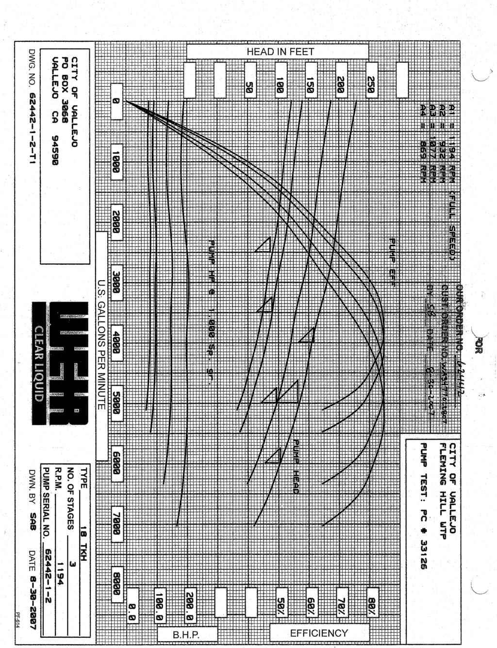
23 3.2 Trans-Vallejo (TV) System via Clearwell Electric-TV Pump Station Segment Analysis The clearwell pumps pipeline is broken down and analyzed in the following segments Segment 1 - Pump Inlet and Outlet - Modified Curves The pump inlet consists the pump entrance and pump outlet. The pump outlet consists of a discharge head, butterfly valve, an 18-inch x 30-inch reducer, and a wye. It is assumed that the pump performance curve contains losses from the pump inlet and discharge head. The losses from these segment are not added to the system curve, but rather subtracted from the manufacturer's pump curves. This modified curve approach is used to model parallel pump systems (Ref. Page 10.38, Pumping Station Design Manual 3rd Edition, Garr Jones et al, 2008) Segment 2 - Header to Concrete Block Segment 2 comprises the pipeline from the electric TV pumps to the concrete block adjacent to the pump station. This segment consists of approximately feet of 30-inch pipe, three 90 elbows, one 45 elbow, and one branch flow tee Segment 3 - Concrete Block to FWPS TV Pumps Tie-In Segment 3 comprises the pipeline from the concrete block, to the tie-in with the Fleming Hill P.S. TV pumps. This segment consists of approximately 75 feet of piping, one 22.5º elbow, and a tee line-flow Segment 4 - Header Tie-in to North-TV Branch. Segment 4 comprises the segment the clearwell pump tie-in tee to the North-TV Branch. This segment contains approximately 35 feet of pipe and one flowmeter Scenarios The scenarios presented in the three system curves are the same as those for the FWPS TV pumps described in Section of this TM Existing Pump The existing clearwell TV pumps are two vertical turbine pumps installed on the roof on the clearwell with the pump intake extending into the clearwell. The current pumps are Weir Floway pumps model 18 TKH 3-stage pumps installed in In Figure 1.5, the clearwell pumps are plotted with the existing clearwell system as described above. October DRAFT 1-14 pw:\\carollo/documents\client/ca/vallejo/7784b10/deliverables/hydraulic Analysis TM\TM 1 - Hydraulic Analysis and Pump Selection.docx
24
25 Head (ft) Figure 5 - Clearwell Trans-Vallejo System - Existing Vertical Turbine Pumps TV-Zone Average Day Demand 12.4 MGD TV-Zone Max Day Demand 17.5 MGD Current TV Max 25 MGD Max Speed: 1200 RPM FT Reservoir, 319 FT Pressure High Friction Factor ETV Zone (H) ETV Zone (M) ETV Zone (L) FT Reservoir, 292 FT Pressure Medium Friction Factor 19 FT Reservoir, 261 FT Pressure Low Friction Factor % Speed 67% Speed TV Pumps Flow (gpm)
26
27 4.0 TV ZONE PUMP ALTERNATIVES AND LAYOUT All four existing TV pumps in the FWPS will be replaced with new electric motor-driven pumps. There are two viable alternatives for replacements for the existing pumps in the FWPS: Vertical turbine pumps. Horizontal split-case pumps. The Pump Alternatives and Life Cycle Analysis Memorandum presented in Appendix A discusses in detail the pros and cons of each alternative and the associated estimated life cycle costs. 4.1 Horizontal Split-Case Pumps with Electric Motor The Horizontal split-case pumps have the advantage of using the existing pump pads and do not require additional modifications to the roof or floor slab. Due to the limited space in the FWPS, it is recommended to arrange the new TV pumps and piping headers similar to the existing configuration. Figure 1.6 shows a model rendering of this option. Computational Fluid Dynamic (CFD) modeling of the pumping system will be performed during final design to optimize pump intake hydraulics. 4.2 Vertical Turbine Pumps Vertical turbine pumps have more flexibility in the intake conditions. They are also the same type of pumps as the clearwell pumps. Installing vertical turbine pumps in the FWPS would require constructing openings and hatches in the pump station roof and also excavating below the pump station slab. This option would require the use of a crane for removal of the pump for servicing and overhauls. The layout of the pumps would be adjusted to so that the pumps can be lifted in and out of the pump station without interfering with the roof beams. Due to the lack of a wetwell, the pumps would be installed in barrels. Figure 1.7 shows a model rendering of this option. There is some construction risk in the installation of the pump and barrel due to unknown subgrade conditions and excavation on the underside of the clearwell that could lead to schedule delays. October DRAFT 1-15 pw:\\carollo/documents\client/ca/vallejo/7784b10/deliverables/hydraulic Analysis TM\TM 1 - Hydraulic Analysis and Pump Selection.docx

28 Figure 6 - Layout of Horizontal Split-case Pumps

29 Figure 7 - Layout of Vertical Turbine Pumps
30 4.3 Pump Controls Due to the shape of the pump curves as illustrated in Figure 1.3 and 1.4, the control strategy differs slightly between the preliminary vertical turbine pump and horizontal splitcase pump selections. For the vertical turbine pumping system, the speed of the pumps in the operation will increase until the desired flow setpoint is reached. If the pumps in operation reaches the max speed and the flow is still below the set point, the PLC will call on the next pump to operate at its starting speed and all pumps in operation will ramp down to that speed. The pumps then will ramp up in speed and repeat the process until the flow setpoint is reached. For the horizontal split-case pumps, the PLC will determine the number of pumps to operate based on the flow setpoint. For example, selecting a flow of 10,000 gpm will call three pumps to operate as three pump operation has full system curve coverage at that flow rate. Similarly, selecting a flow above 15,000 gpm will call all four pumps to operate. The pumps will start in their starting speed and ramp up until the flow setpoint is reached. In short, there is no benefit or drawback relative to the control system configurations that would affect the selection of the pump type. 4.4 Recommended Alternative The horizontal split case pump alternative offers easy access for maintenance and has significantly less construction risks than the vertical turbine pump alternative. In addition, the life cycle costs are estimated to be lower for the horizontal split-case pumps. Based on the advantages and the life cycle costs, the replacement of existing TV pumps with new horizontal split-case pumps is recommended. October DRAFT 1-19 pw:\\carollo/documents\client/ca/vallejo/7784b10/deliverables/hydraulic Analysis TM\TM 1 - Hydraulic Analysis and Pump Selection.docx
31 Technical Memorandum No. 1 APPENDIX A PUMP ALTERNATIVES COMPARISON AND LIFE CYCLE ANALYSIS October DRAFT pw:\\carollo/documents\client/ca/vallejo/7784b10/deliverables/hydraulic Analysis TM\TM 1 - Hydraulic Analysis and Pump Selection.docx
32
33 PROJECT MEMORANDUM Project Name: Finished Water Pump Station Electrification Project Date: September 1, 2015 Client: City of Vallejo Project No: 7784B.10 Prepared By: Reviewed By: Subject: George Chin, P.E. Peter von Bucher, P.E. Pump Alternatives Comparison and Life Cycle Analysis Background There are two viable alternatives for replacements for the existing pumps in the Finished Water Pump Station (FWPS): 1) Vertical turbine pumps. 2) Horizontal split-case pumps. Each type has various pros and cons related to efficiency, constructability, and maintenance. Purpose The purpose of this memorandum is to present a basic life cycle cost analysis comparing the use of vertical turbine pumps to horizontal split-case pumps for the TV Zone. Summary of Findings Based on the assumptions described in this memorandum: Vertical turbine pumps would save approximately $5,000 per year in energy costs. Horizontal split-case pumps would save approximately $250,000 in capital costs. Horizontal split-case pumps would save approximately $239,000 over a 20 year life span, largely due to lower capital costs and lower assumed maintenance costs. Discussion Table 1 summarizes the life cycle analysis (LCA) performed for each of the two alternatives. The LCA considers the following elements: Capital costs including structural/mechanical improvements associated with each pump alternative. Annual non-energy operating costs. Annual electricity costs. Annual maintenance costs. Non-recurring costs such as pump overhauls. 1 pw:\\carollo/documents\client/ca/vallejo/7784b10/deliverables/hydraulic Analysis TM\Life Cycle Analysis.docx
34 Table 1 Summary of Life Cycle Costs (1) Alternatives Capital Cost Annual Non- Energy Operation Annual Energy Annual Maintenance Total Annual O&M Present Value Relative Difference Alternative 1 - Horizontal Split Case Pumps (4 pumps) $1,810,000 $28,000 $203,000 $6,000 $237,000 $6,428,000 0% Alternative 2 - Vertical Turbine Pumps (4 $2,060,000 $28,000 $198,000 $11,000 $237,000 $6,667,000 4% pumps) Notes: (1) Cost presented is in 2018 dollars. Life cycle cost is for 20 years. Assumptions The LCA was conducted using the following parameters: Inflation Rate: 3 percent. Discount Rate: 5 percent. Energy Escalation Rate: 5 percent. Starting Year: Number of Years: 20. The LCA compares replacement of all 4 existing TV Zone pumps with new horizontal split-case or vertical turbine pumps. The capital cost of the alternative includes only the additional structural and mechanical improvements directly related to the type of pump. For example, the vertical turbine alternative requires additional structural modifications in the roof and the installation of the pump barrels under the pump station. Additional structural improvements to bring the pump station up to the Building Code, electrical improvements including VFDs and new MCCs, and instrumentation costs are not included in the capital cost for this LCA, as these costs will be the same for each alternative. Energy Costs: The 2035 TV-zone Annual Average Day Demand (ADD) from the Master Plan was used for comparing energy costs between the alternatives. The LCA assumed that two pumps will be operated to meet the ADD, three pumps will be operated for the Maximum Day Demand (MDD), and a fourth pump will be provided for standby. The clearwell electric-tv pumps are assumed to be not in operation for the LCA. Table 2 below summarizes the parameters used for the energy comparison. 2 pw:\\carollo/documents\client/ca/vallejo/7784b10/deliverables/hydraulic Analysis TM\Life Cycle Analysis.docx
35 Table 2 Design Point for Energy Comparison Parameter Value Flow 8581 gpm Pressure (in elevation) 292 FT Clearwell Water Level 15 FT No. Pumps in Operation 2 Flow Per Pump 4290 gpm The pump curves and the design point for each alternative are shown in Figures 1 and 2. 3 pw:\\carollo/documents\client/ca/vallejo/7784b10/deliverables/hydraulic Analysis TM\Life Cycle Analysis.docx
36
37 Head (ft) Figure 1. Trans-Vallejo System - Finished Water Pump Station Flowserve 250LNN325 (Horizontal Split Case) TV -Zone Average Day Demand 12.4 MGD TV-Zone Max Day Demand 17.5 MGD Max Speed: 1775 RPM Design Point for Life Cycle Analysis FT Reservoir, 319 FT Pressure High Friction Factor FT Reservoir, 292 FT Pressure Medium Friction Factor % Speed FT Reservoir, 261 FT Pressure Low Friction Factor % Speed 65% Speed TV Zone (H) TV-292 TV Zone (L) TV Pumps Flow (gpm)
38
39 Head (ft) Figure 2. Trans-Vallejo System - Finished Water Pump Station Weir/Floway 18TKH (Vertical Turbine) Max Speed: 1200 RPM TV -Zone Average Day Demand 12.4 MGD TV-Zone Max Day Demand 17.5 MGD Design Point for Life Cycle Analysis 11 FT Reservoir, 319 FT Pressure High Friction Factor FT Reservoir, 292 FT Pressure Medium Friction Factor FT Reservoir, 261 FT Pressure Low Friction Factor % Speed 76 TV Zone (H) TV-292 TV Zone (L) % Speed 65 60% Speed TV Pumps Flow (gpm)
40
41 The pump curves show that the vertical turbine pump is approximately 2 percent more efficient than the horizontal split case pump around the BEP (best efficiency point) and the POR (preferred operating range). For this LCA, the horizontal split-case pumps are assumed to be 82 percent efficient and the vertical turbine pumps are assumed to be 84 percent efficient. Non-Energy Operational Costs: The following non-energy operational procedures are included in the LCA: Daily Operations Check on Pumping System (30 min/day) Weekly Maintenance Check on Pumps (30 min/week per pump) Monthly Maintenance Pump Runs (30 min/month per pump) The costs of these procedures are the same between these two alternatives as the removal of the pump will not be required for these operations. The labor cost of an operator performing these procedures is assumed to be $90/hr. Maintenance Costs: The following maintenance procedures are included in the LCA: Annual Pump Preventative Maintenance Service (8 hours/year per pump) Annual Motor Preventative Maintenance Service (8 hours/year per pump) The labor cost of a maintenance staff performing these services is assumed to be $90/hr. For the vertical turbine alternative, a crane will be required for removing the pump from the barrel to be serviced. Four hours of the crane crew cost at $320.78/hour is included for this operation. The LCA assumes that each pump and motor will need a preventative maintenance service once a year. Non-recurring Maintenance Costs: The LCA assumes a pump overhaul for each of the pumps at the 10 year interval. The overhaul includes replacement of shaft and sleeve, bearings, impeller and wear ring. The cost of the overhaul is assumed to be 30 percent of the quoted cost of the pump. Advantages and Disadvantages of Alternatives Table 3 summarizes the advantages and disadvantages of each alternative: Table 3 Advantages and Disadvantages of Alternatives Alternative Horizontal Split-case pumps Vertical Turbine Pumps Advantages Disadvantages Easy to maintain and inspect. Straightforward construction and installation. Occupies a larger footprint in the pump station. More expensive equipment. Slightly more efficient. Same type of pump as clearwell pumps. More flexibility in achieving optimal intake conditions. Significant construction risk in the installation of the pump and barrel in an existing building. Requires crane for removal of pump for servicing and overhauls. 6 pw:\\carollo/documents\client/ca/vallejo/7784b10/deliverables/hydraulic Analysis TM\Life Cycle Analysis.docx
42 Recommendation The horizontal split case pump alternative offers easy access for maintenance and has significantly less construction risks than the vertical turbine pump alternative. In addition, the life cycle costs are estimated to be 4 percent lower for the horizontal split-case pumps. Based on the advantages and the life cycle costs, the replacement of existing TV pumps with new horizontal split-case pumps is recommended. 7 pw:\\carollo/documents\client/ca/vallejo/7784b10/deliverables/hydraulic Analysis TM\Life Cycle Analysis.docx
43 Attachment A Manufacturer Pump Curves pw:\\carollo/documents\client/ca/vallejo/7784b10/deliverables/hydraulic Analysis TM\Life Cycle Analysis.docx

44
45
CITY OF VALLEJO FINISHED WATER PUMP STATION ELECTRIFICATION PROJECT PRELIMINARY DESIGN REPORT. FINAL December 2015
 This document is released for the purpose of information exchange review and planning only under the authority of Peter Briggs von Bucher, 12/11/2015, State of California, PE No. 79446. It is not to be
Appendix J Effluent Pump Station
 Appendix J Effluent Pump Station TECHNICAL MEMORANDUM Salmon Creek Treatment Plant Effluent Pump Station Hydraulics and Phasing Analysis for the Phase 5A Project Columbia River Outfall and Effluent Pipeline
Session 2 Pump Selection. Mark Markham, P.E. Gresham, Smith and Partners September 14, 2017
 Session 2 Pump Selection Mark Markham, P.E. Gresham, Smith and Partners September 14, 2017 Quick Refresh System Curves graphically show the relationship between flow rates and associated total dynamic
Pumps and Pumping Stations
 Pumps and Pumping Stations Pumps add energy to fluids and therefore are accounted for in the energy equation Energy required by the pump depends on: Discharge rate Resistance to flow (head that the pump
McDuff WTP High Service Pump Replacement
 T E C H N I C A L M E M O R A N D U M 642-03 MCDUFF WTP HIGH SERVICE PUMP REPLACEMENT 642-03 McDuff WTP High Service Pump Replacement PREPARED FOR: PREPARED BY: Capital Budget Planning Craig Jones DATE:
Water Treatment Plant Phase 1 Upgrades CMAR Selection Pre-Submittal Meeting
 Water Treatment Plant Phase 1 Upgrades CMAR Selection Pre-Submittal Meeting October 12, 2017 Water Treatment Plant Phase 1 Upgrades 22 mgd WTP Expand capacity to 32 mgd Upgrades to most processes Only
AR No. # Efficient Irrigation
 AR No. # Efficient Irrigation Recommendation Optimize the facilities irrigation pumping system by ensuring pumps are operating at their Best Efficiency Point (BEP). We estimate the system pumping efficiency
Norwood High Service Pump Replacement
 T E C H N I C A L M E M O R A N D U M 737-02 NORWOOD HIGH SERVICE PUMP REPLACEMENT 737-02 Norwood High Service Pump Replacement PREPARED FOR: JEA Planning PREPARED BY: Joshua M. Brown DATE: February 2017
City of Fairfax, Virginia City Council Regular Meeting. Honorable Mayor and Members of Cfy ;ouncil Robert L. Sisson, City Manager /I.
 City of Fairfax, Virginia City Council Regular Meeting Agenda Item #..,.,C:::o~Or!---!h~--- city Council Meeting q+----4-j/.-...:cx:l..-.>o?...~-/_,_j-=2=; r 1 TO: FROM: SUBJECT: ISSUE(S): SUMMARY: Honorable
Section 7 Hydraulic Model Development and Evaluation Criteria
 Section 7 Hydraulic Model Development and Evaluation Criteria The hydraulic evaluation conducted to develop this master plan was performed using a computer model of the reclaimed water distribution system.
GREEN PROJECT RESERVE BUSINESS CASE CITY OF BROKEN ARROW WATER SUPPLY IMPROVEMENTS PROJECT
 GREEN PROJECT RESERVE BUSINESS CASE CITY OF BROKEN ARROW WATER SUPPLY IMPROVEMENTS PROJECT July, 2011 The Oklahoma Water Resources Board (OWRB) requires a Business Case be made for projects or certain
PRELIMINARY WASTEWATER CAPACITY STUDY
 PRELIMINARY WASTEWATER CAPACITY STUDY Tentative Tract Map No. 18955 CITY OF HESPERIA Prepared for: HESPERIA VENTURES I, LLC 10410 Roberts Road Calimesa, CA 92320 Tel (714) 785 2381 Mr. John Ohanian Prepared
75 th STREET WASTEWATER TREATMENT PLANT UPGRADES PROJECT
 75 th STREET WASTEWATER TREATMENT PLANT UPGRADES PROJECT Basis of Design Memorandum Design Memo No.: DM-7 (REVISED) Date: February 2005 Project/Task: 124487.001.420 Subject: Prepared by: Reviewed by: Hydraulic
6.2.1 Intermediate Pumping Overview
 6.2.1 Intermediate Pumping Overview The intermediate pumps are the feed pumps to the MBR system. The pumps take flow from the primary effluent channel and pump it to the channel in front of the fine screens.
Peerless Pump Company Handbook of Engineering Data
 Peerless Pump Company Handbook of Engineering Data Brochure EM77 DEFINITION OF PUMP TERMS A.1 A line shaft vertical turbine pump is a vertical-shaft centrifugal or mixed-flow pump with rotating impeller
Examine Pump, Process & Control Elements to Solve Fluid Piping System Problems
 Examine Pump, Process & Control Elements to Solve Fluid Piping System Problems by Ray Hardee My past Pumps & Systems columns (read them here) have dealt with using basic engineering principles to better
South Davis Sewer District Pump Station Hydraulic Capacity Evaluation
 Utah State University DigitalCommons@USU All Graduate Plan B and other Reports Graduate Studies 5-11 South Davis Sewer District Pump Station Hydraulic Capacity Evaluation James W. Dixon Utah State University
Calculate the Costs of Piping System Elements
 Calculate the Costs of Piping System Elements by Ray Hardee, Engineered Software, Inc. Last month s column described the process of creating an energy cost balance sheet for a piping system (see Figure
Observations from Several Condition Assessments of Prestressed Concrete Cylinder Pipe used at Energy Generation Facilities
 147 Observations from Several Condition Assessments of Prestressed Concrete Cylinder Pipe used at Energy Generation Facilities Todd Stong PE 1, Ron R. Jorgenson 2, and Jacob Sauer 3 1 Senior Engineer,
TECHNICAL MEMORANDUM
 TECHNICAL MEMORANDUM Project Name: Finish Water Pump Station (FWPS) Date: October 15, 2015 Client: City of Vallejo Project Number: 07784B.10 Prepared By: Reviewed By: Subject: Crystal Starr, P.E. Mike
Conflict Resolution: Pump & System Interaction. April 13, 2017
 Conflict Resolution: Agenda What is a system curve and what is it good for? Friction vs. static head dominated systems Effects of manual vs. control valves Affinity laws Parallel composite curves When
APPENDIX B. WSSC Design Criteria for Water Distribution Systems
 a. System Requirements ) Pressure Requirements APPENDIX B WSSC Design Criteria for Water Distribution Systems a) The water distribution system shall have adequate capacity to supply domestic demand to
CHAPTER 8 CAPITAL IMPROVEMENT PLAN
 INTRODUCTION CHAPTER 8 CAPITAL IMPROVEMENT PLAN This chapter presents 6-, 10-, and 20-year Capital Improvement Plans (CIPs) in accordance with the requirements of WAC 26-290. Water system capital improvements
Pittsburgh Water Treatment Plant Projects. by Jay R. Lucas, P.E. Senior Project Manager
 Pittsburgh Water Treatment Plant Projects by Jay R. Lucas, P.E. Senior Project Manager Who Is American Water We are the largest publicly traded water and wastewater utility in the United States Broad national
WASTEWATER TREATMENT PLANT MASTER PLAN 6. BUSINESS CASE EVALUATION OF ALTERNATIVES
 WASTEWATER TREATMENT PLANT MASTER PLAN 6. BUSINESS CASE EVALUATION OF ALTERNATIVES A range of potential ammonia limits were identified for alternatives evaluation, as discussed in Section 2.2.5. This chapter
CHAPTER 8 CAPITAL IMPROVEMENT PLAN
 INTRODUCTION CHAPTER 8 CAPITAL IMPROVEMENT PLAN This chapter presents a 10-year Capital Improvement Plan (CIP). Wastewater capital improvements have been scheduled and prioritized on the basis of growth,
Task 5. Christopher Mack Zack Kaldy MET 330 Fluid Mechanics November 8, Purpose
 Purpose Task 5 Christopher Mack Zack Kaldy MET 330 Fluid Mechanics November 8, 2015 For the fifth task of this project we are asked to specify the layout of the piping system, the material type and sizes
CITY OF SASKATOON DESIGN AND DEVELOPMENT STANDARDS MANUAL SECTION FOUR WATER DISTRIBUTION SYSTEM
 CITY OF SASKATOON DESIGN AND DEVELOPMENT STANDARDS MANUAL SECTION FOUR WATER DISTRIBUTION SYSTEM 2018 TABLE OF CONTENTS Section Four Water Distribution System SECTION PAGE NUMBER 1. Objective...1 2. Submissions
About Me. Overview. Seattle Regional Water System. Seattle Regional Water System. Water System Analysis and Design at Seattle Public Utilities
 About Me Water System Analysis and Design at Seattle Public Utilities Jon C. Ford, P.E. CEE 481 October 1, 8 Senior Civil Engineer, Seattle Public Utilities BSCE, Seattle University MSCE, University of
IMPACT AND PUNCTURING OF JARI TUNNEL AND ENLARGEMENT OF EXISTING TAPPINGS FOR ADDITIONAL WATER SUPPLY AND POWER GENERATION
 117 Paper No. 738 IMPACT AND PUNCTURING OF JARI TUNNEL AND ENLARGEMENT OF EXISTING TAPPINGS FOR ADDITIONAL WATER SUPPLY AND POWER GENERATION JAVED MUNIR, SYED ABBAS ALI, IRFAN MAHMOOD 118 Javed Munir,
Siphonic Roof Drainage & Design Process. Presentation by
 Siphonic Roof Drainage & Design Process Presentation by What is Siphonic Roof Drainage? Siphonic Roof Drainage is an innovative solution which utilises the power of a natural siphon to create a high-performance
Appendix VIII. Hazen and Sawyer Technical Memorandum: Option 4: Permanent Haw River Intake. and. Supporting Tables Showing Results of OWASA Analysis
 Appendix VIII. Hazen and Sawyer Technical Memorandum: Option 4: Permanent Haw River Intake and Supporting Tables Showing Results of OWASA Analysis TECHNICAL MEMORANDUM Option 4: Permanent Haw River Intake
Enid Alternate Water Supply
 City of Enid, Oklahoma Prepared by: 1016 24 th Ave NW Norman, OK 73069 June 2016 1.0 Introduction The City of Enid, Oklahoma (City) has historically enjoyed an adequate supply of water resources to support
Fullerton Reservoirs
 Fullerton Reservoirs 63 Million Gallons of New Finished Water Storage for the Baltimore Distribution System Gannett Fleming, Inc. Nicholas Lewis, PE Dennis Funk, PE Baltimore County Department of Public
The City of Baltimore Back River Wastewater. No more backups Reducing SSOs with headworks improvements in Baltimore
 No more backups Reducing SSOs with headworks improvements in Baltimore Brian Balchunas, Meredith Welle, Jason Kerns, Gurminder Singh, Misrak Shiferaw, Ben Asavakarin, Thomas Demlow, and Kara Hurtig The
TABLE OF CONTENTS PART III MINIMUM DESIGN STANDARDS Section 115 WATER DISTRIBUTION SYSTEM GENERAL SIZING LINES 115.
 TABLE OF CONTENTS PART III MINIMUM DESIGN STANDARDS Section 115 WATER DISTRIBUTION SYSTEM SECTION TITLE PAGE 115.1 GENERAL 115.1 115.2 SIZING LINES 115.1 115.3 DISTRIBUTION SYSTEM 115.2 115.3.1 Layout
MEMORANDUM. The general findings of the assessment are as follows:
 November 28, 2006 MEMORANDUM Project No.: 030009-002-01 To: From: Re: WRIA 31 Planning Unit Steve Germiat, LHG, CGWP, and Timothy J. Flynn, LHG, CWGP Evaluation of Winterizing Existing River Pump/Conveyance
N N O V A T I O N E F F I C I E N C Y Q U A L I T Y VTG. Vertical Turbine Generator
 N N O V A T I O N E F F I C I E N C Y Q U A L I T Y VTG For more than 60 years the name Ruhrpumpen has been synonymous worldwide with innovation and reliability for pumping technology Ruhrpumpen is an
Utility Partner Data Report
 Utility Partner Data Report Project Title: Studying Distribution System Hydraulics and Flow Dynamics to Improve Water Utility Operational Decision Making Water Distribution System: Paris, Kentucky Project
By Kimbal A. Hall, PE. Submitted to: WESTFALL MANUFACTURING COMPANY. May ALDEN RESEARCH LABORATORY, INC. 30 Shrewsbury Street Holden, MA 01520
 COMPUTATIONAL FLOW MODEL OF WESTFALL'S 36 3050 THREE STAGE MIXER TO BE INSTALLED IN THE PERCHLORATE BLENDING STATION FOR THE CITY OF REDLANDS, CALIFORNIA GFS-411507-1R2 By Kimbal A. Hall, PE Submitted
Water and wastewater treatment operations
 The Search for Energy Savings: Optimization of Existing & New Pumping Stations Chris Reinbold and Vincent Hart Water and wastewater treatment operations account for 30 to 50 percent of all municipal power
TOWN OF MOUNT PLEASANT WESTCHESTER COUNTY, NEW YORK
 TOWN OF MOUNT PLEASANT WESTCHESTER COUNTY, NEW YORK COST EVALUATION FOR ROLLING HILLS AREA WATER MAIN EXTENSION PROFESSIONAL CONSULTING, LLC. Octagon 10, Office Center 1719 Route 10, Suite 225 Parsippany,
DRAFT TECHNICAL MEMORANDUM
 Stetson Engineers, Inc. Technical Memorandum - New City of Solvang Well Field, May 14, 2010 DRAFT TECHNICAL MEMORANDUM 2171 E. Francisco Blvd., Suite K San Rafael, California 94901 TEL: (415) 457-0701
MATHEMATICS FOR WATER OPERATORS
 MATHEMATICS FOR WATER OPERATORS Mathematics The understanding of the mathematics of water hydraulics (flows, pressures, volumes, horsepower, velocities) and water treatment (detention time, chemical dosage)
Stretching NPSHA vs. NPSHR to the Limit
 Feedwater Systems Reliability Users Group (Jan 2017) Austin, TX Stretching NPSHA vs. NPSHR to the Limit Presenter: Art Washburn P.E. DISCUSSION POINTS Two Rules to Get You Home and Plant Priorities Customer
CHAPTER 5. COLLECTION SYSTEM ALTERNATIVES
 CHAPTER 5. COLLECTION SYSTEM ALTERNATIVES This chapter evaluates alternative wastewater collection system technologies. Each technology is described along with the relative advantages and drawbacks for
Tank Name: Cornwell 0.5MG Reservoir
 TIDEFLEX MIXING SYSTEM (TMS) PRELIMINARY DESIGN REPORT Tank Name: Cornwell 0.5MG Reservoir Water Utility/Owner: Soquel Creek Water District, CA Consultant: CONTENTS TMS - GENERAL ARRANGEMENT DRAWING CFD
I - 15 CORRIDOR CAMPUS MASTER PLAN DRAFT EIR MT. SAN JACINTO COMMUNITY COLLEGE DISTRICT. Appendices
 I - 15 CORRIDOR CAMPUS MASTER PLAN DRAFT EIR MT. SAN JACINTO COMMUNITY COLLEGE DISTRICT Appendices Appendix J Utility Systems Data August 2017 I - 15 CORRIDOR CAMPUS MASTER PLAN DRAFT EIR MT. SAN JACINTO
Water & Wastewater Operation: Pipe Systems, System Curves, & Pump Curves
 Water & Wastewater Operation: Pipe Systems, System Curves, & Pump Curves Matt Prosoli PumpsPlus Inc. 30 Years in Water & Wastewater BA in Marketing, Michigan State Univ. MWEA Maintenance Committee 30 years
Facilities Plan. Technical Memorandum No. TM-WW-7 Hydraulic Analysis and Effluent Pump Station
 City of St. Joseph, Missouri Hydraulic Analysis and Effluent Pump Station By Work Order No. 09-001 B&V Project 163509 May 20, 2010 Table of Contents 1.0 Executive Summary...1 2.0 Purpose of Study...2 3.0
SAWEA Workshop 2010 Innovative Water and Wastewater Networks Presented by Greg Welch, AECOM
 SAWEA Workshop 2010 Innovative Water and Wastewater Networks Presented by Greg Welch, AECOM Basic Hydraulic Principles Open channel flow Closed conduit / pressurized flow systems Orifices, weirs and flumes
Table of Contents. 3.1 Source Capacity Analysis
 Table of Contents 3.1 Source Capacity Analysis... 3-1 3.1.1. Design Criteria... 3-1 3.1.2. Source Capacity Evaluation... 3-1 3.1.2.1 Plateau Zone... 3-1 3.1.2.2 Cascade View Zone... 3-4 3.2 Storage Capacity
Table A Summary Water System Data Data
 PS OMAS TECHNICAL MEMORANDUM NO. 2 To: From: Trish Rhay, Mark Cuneo Mike Swan, PE, Harvey Gobas, PE and Neha Gajjar, PE Date: Subject: EXECUTIVE SUMMARY The of Beverly Hills (CBH) has ten (10) active reservoirs
Presentation Outline. Historical Perspective on Wet Wells. Historical Perspective on Wet Well Design. The Trench-Type Self-Cleaning Wet Well
 Sludge and Scum-Sucking Submersible Sewage Pump Station (A Unique Approach to the Self-Cleaning Wet Well Design) Timothy M. Schneller, P.E. George Butler Associates, Inc. Lenexa, Kansas Presentation Outline
Ivins City Standard Specifications for Design and Construction Part 2 Engineering and Design Standards
 2.9. WATER SYSTEM DESIGN Ivins City Standard Specifications for Design and Construction All culinary water mains and appurtenances shall be designed to provide for adequate future service for all contiguous
DIVISION 15- MECHANICAL Section Fire Pumps
 DIVISION 15- MECHANICAL Section 15320 Fire Pumps 1.00 PART 1 -GENERAL 1.01 DESCRIPTION OF WORK: A. Provide pumps for fire suppression. 1.02 SECTION INCLUDES: A. Vertical Turbine Fire Pump RELATED DOCUMENTS:
Gregory J. Eldridge, P.E. Vice President Haley and Ward, Inc.
 Gregory J. Eldridge, P.E. Vice President Haley and Ward, Inc. July 2012 Howe Street Water Supply Site There are 5 wells located at the Howe Street site All 5 wells are gravel packed wells with at least
Utility Partner Data Report
 Utility Partner Data Report Project Title: Studying Distribution System Hydraulics and Flow Dynamics to Improve Water Utility Operational Decision Making Water Distribution System: Nicholasville, Kentucky
Capital Investment Plan (CIP) Quarterly Report for the period ending December 2013
 Quarterly Report for the period ending December 2013") Report Engineering Services Group Capital Investment Plan (CIP) Quarterly Report for the period ending December 2013 Summary This report provides a summary of fiscal year accomplishments, capital expenditures
Report Engineering Services Group Capital Investment Plan (CIP) Quarterly Report for the period ending December 2013 Summary This report provides a summary of fiscal year accomplishments, capital expenditures
PRELIMINARY REGIONAL WATER IMPACT FEE FACILITIES PLAN & ANALYSIS CALCULATIONS WASHINGTON COUNTY, UTAH
 PRELIMINARY REGIONAL WATER IMPACT FEE FACILITIES PLAN & ANALYSIS CALCULATIONS WASHINGTON COUNTY, UTAH SECTION A: DEMAND CONSIDERATIONS SECTION B: SUPPLY CONSIDERATIONS SECTION C: EXISTING PROJECTS WITH
EXAMPLE SHEET FOR TOPIC 2 AUTUMN Q1. What is the significance of the Reynolds number Re for the flow of fluid in a circular pipe?
 EXMPLE SHEET FOR TOPI 2 UTUMN 2013 Q1. What is the significance of the Reynolds number Re for the flow of fluid in a circular pipe? If the friction factor for a pipe is given by λ = 64/Re for laminar flow,
/ Marley Series 10 Series 15 Cooling Tower /
 / Marley Series 10 Series 15 Cooling Tower / / The Marley Difference / Series 10 and Series 15 cooling towers are field constructed, splash fill, crossflow wood cooling towers, designed to serve all normal
COLLECTION AND DISTRIBUTION OF WATER
 COLLECTION AND DISTRIUTION OF WATER Addis Ababa University Addis Ababa Institute of Technology Department of Civil Engineering Collection and Distribution of Water Deals with the transport of water from
MIXING UP THE TWINS ACTIVE MIXING AND OTHER WATER QUALITY CONSIDERATIONS FOR STORAGE TANKS
 MIXING UP THE TWINS ACTIVE MIXING AND OTHER WATER QUALITY CONSIDERATIONS FOR STORAGE TANKS Ray Ihlenburg, PE, Senior Technical Director Thomas Waters, EIT, Staff Engineer O Brien & Gere Louisville, Kentucky
SEWER SYSTEM DESIGN GUIDELINES
 SEWER SYSTEM DESIGN GUIDELINES PART 1 GENERAL 1.1 GENERAL GUIDELINES A. The following sewer system design guidelines are based on Federal, State and Local health requirements, and the Berkeley County Water
Modal Analysis as a Tool to Resolve Pump Vibration Issues
 Modal Analysis as a Tool to Resolve Pump Vibration Issues John Koch HDR, Bellevue, WA jkoch@hdrinc.com ABSTRACT Vibration spectrum analysis and modal analysis are tools designers and plant staff can use
Gate valve; Globe valve; Ball valve; Butterfly valve; Swing-check valve; Angle valve
 03 André G. McDonald and Hugh L. Magande. Published 03 by John Wiley & Sons, Ltd. 3. A junior engineer consults a senior engineer regarding a piping design problem. The junior engineer has determined the
CUP-CVP CONCRETE VOLUTE COOLING WATER PUMP
 CUP-CVP CONCRETE VOLUTE COOLING WATER PUMP SPX - An introduction SPX is a Fortune 500 multi-industry manufacturing leader, headquartered in Charlotte, North Carolina. SPX manufactures and markets products,
Self-Cleaning Trench-Type Wet Well Design
 Self-Cleaning Trench-Type Wet Well Design *Trooper Smith, P.E., Freese and Nichols, Inc. *10814 Jollyville Rd. Building 4, Suite 100 Austin, TX, 78759 PH: (512) 617-3100 Email: tws@freese.com ABSTRACT
Appendix T MRWPCA GWR Discharge Dilution Analysis
 Appendix T MRWPCA GWR Discharge Dilution Analysis Pure Water Monterey GWR Project April 2015 Draft EIR Denise Duffy & Associates, Inc. This Page Left Intentionally Blank Pure Water Monterey GWR Project
Water-side Systems. Ir. Dr. Sam C. M. Hui Faculty of Science and Technology
 SPD5132 Indoor Environment and HVAC Systems http://ibse.hk/spd5132/ Water-side Systems Ir. Dr. Sam C. M. Hui Faculty of Science and Technology E-mail: cmhui@vtc.edu.hk Dec 2016 Contents Pipe Systems and
VILLAGE OF ALGONQUIN 2014 WASTEWATER FACILITY PLAN UPDATE EXECUTIVE SUMMARY
 EXECUTIVE SUMMARY EXECUTIVE SUMMARY INTRODUCTION AND BACKGROUND The Village of Algonquin, located along the Fox River in McHenry County, provides wastewater collection and treatment services to the entire
This existing intake pipe does not have facilities to control or limit intake icing events.
 Memorandum To: From:, Utilities Director Mark White Date: Subject: Memorandum This memorandum discusses the existing 36/42-inch raw water intake at the Evanston water treatment plant (WTP), including a
3.0 DESIGN CRITERIA FOR SANITARY SEWER FACILITIES
 3.0 DESIGN CRITERIA FOR SANITARY SEWER FACILITIES All sanitary sewers shall be designed in accordance with these Design Standards, LBWD Rules and Regulations, and to accepted engineering principles. In
DOWNTOWN SHALL NOT FLOOD AGAIN
 DOWNTOWN SHALL NOT FLOOD AGAIN Robert C. Steidel**, Robert Stone**, Lin Liang*, Edward J. Cronin*, Federico E. Maisch* *Greeley and Hansen LLC 2116 W Laburnum Avenue, Suite 100 Richmond, Virginia 23227
Silver Lake WTP Clearwell Part 2 The Tracer Study PHOTO OPTIONAL. NEWWA 2009 Spring Joint Regional Conference and Exhibition The Value of Water
 Silver Lake WTP Clearwell Part 2 The Tracer Study NEWWA 2009 Spring Joint Regional Conference and Exhibition The Value of Water PHOTO OPTIONAL Louis Soracco, P.E. April, 2009 Discussion Format Background
Eska Creek Preliminary Feasibility Analysis
 Introduction Eska Creek Preliminary Feasibility Analysis This report examines the feasibility issues of energy and economics for a 1.8 MW hydroelectric project on Eska Creek (project). The Project is located
Distribution System Upgrades to Improve Water Quality
 Distribution System Upgrades to Improve Water Quality Christopher Evans, P.E., Hatch Mott MacDonald Outline Replace Water Lines Project Project Purpose Study Phase Utility Source Evaluation Elevated Storage
MUNICIPAL WASTEWATER PUMP STATION DESIGN PROBLEMS AND SOLUTIONS Jeff Chapin, P.E. Dewberry 8401 Arlington Boulevard Fairfax, VA 22032
 MUNICIPAL WASTEWATER PUMP STATION DESIGN PROBLEMS AND SOLUTIONS Jeff Chapin, P.E. Dewberry 8401 Arlington Boulevard Fairfax, VA 22032 ABSTRACT The growth of the Northern Virginia Area around Washington
Table of Contents. Foreword... xvii Executive Summary... xxi. Chapter One Pump Fundamentals, 1
 Foreword................................................ xvii Executive Summary........................................ xxi Chapter One Pump Fundamentals, 1 1.1 Introduction..........................................
SUPPLEMENTAL MECHANICAL CORRECTION SHEET FOR SEWAGE EJECTORS AND SUMP PUMPS 2011 LAPC
 SUPPLEMENTAL MECHANICAL CORRECTION SHEET FOR SEWAGE EJECTORS AND SUMP PUMPS 2011 LAPC This is intended to provide uniform application of the codes by the plan check staff and to help the public apply the
USING DESIGN-BUILD TO MITIGATE RISK TO A MAJOR WATER DELIVERY SYSTEM ROCKY MOUNTAIN DBIA PRESENTATION MAY 20, 2016
 USING DESIGN-BUILD TO MITIGATE RISK TO A MAJOR WATER DELIVERY SYSTEM ROCKY MOUNTAIN DBIA PRESENTATION MAY 20, 2016 PRESENTATION OVERVIEW Utilities / Water System Overview Project Requirements Team Selection
MENIFEE VALLEY CAMPUS MASTER PLAN DRAFT EIR MT. SAN JACINTO COMMUNITY COLLEGE DISTRICT. Appendices
 MENIFEE VALLEY CAMPUS MASTER PLAN DRAFT EIR MT. SAN JACINTO COMMUNITY COLLEGE DISTRICT Appendices Appendix J Utility Systems Data February 2017 MENIFEE VALLEY CAMPUS MASTER PLAN DRAFT EIR MT. SAN JACINTO
Exploration of Utulei Clarigester #1 for Facility Upgrade
 Pacific Design Build Corporation 1036 Mikole St. Honolulu, HI 96819 Phone #: (808) 841-6685 Fax#: (808) 843-1797 I. Objective: Exploration of Utulei Clarigester #1 for Facility Upgrade At the request of
CHAPTER 12 TRICKLING FILTER PLANTS
 CHAPTER 12 TRICKLING FILTER PLANTS TM 5-814-3/AFM 88-11, Volume III 12-1. General considerations. Trickling filter plants have been justified by their low initial cost, low operating and maintenance costs,
PRIVATE STORM DRAINAGE FACILITIES REQUIREMENTS
 PRIVATE STORM DRAINAGE FACILITIES REQUIREMENTS 39 AUGUST 2005 TABLE OF CONTENTS PRIVATE STORM DRAINAGE FACILITIES REQUIREMENTS PAGE SECTION 1 DESIGN CRITERIA 41 SECTION 2 SUBMITTAL 44 SECTION 3 STRUCTURES
Booster Pump Fundamentals. By: Bill Baglot
 Booster Pump Fundamentals By: Bill Baglot March 22, 2010 1 Booster Pumps Presentation Topics What are Booster Pumps and when do we need them Accurately sizing boosters and drawdown tanks Maximizing Energy
Start-up of a Secondary Water Supply Company. and First Phase Design of a Regional System
 Start-up of a Secondary Water Supply Company and First Phase Design of a Regional System by Stephen W. Smith and Amy L. Johnson Abstract. Highland Ditch Company formed the Highland Secondary Water Company
City of Oxnard. Public Works Integrated Master Plan
 City of Oxnard This document is released for the purpose of information exchange review and planning only under the authority of Hugh Steve McDonald, December 2015, State of California, PE No. 44074 and
City of Walnut Creek Development Review Services 1666 N. Main Street, Walnut Creek, CA (925) phone (925) fax
 phone (925) fax") City of Walnut Creek Development Review Services 1666 N. Main Street, Walnut Creek, CA 94596 (925) 943-5834 phone (925) 256-3500 fax Issued July 22, 2010 Information Bulletin No. IB-016 DOCUMENT SUBMITTAL
City of Walnut Creek Development Review Services 1666 N. Main Street, Walnut Creek, CA 94596 (925) 943-5834 phone (925) 256-3500 fax Issued July 22, 2010 Information Bulletin No. IB-016 DOCUMENT SUBMITTAL
Sizing Guidelines for New or Replacement Sewage Pumps
 Sizing Guidelines for New or Replacement Sewage Pumps Deron B. Oberkorn SSPMA Technical Committee Member 1 SSPMA Sump and Sewage Pump Manufacturers Association Since 1956, we are a North American trade
Sump Pumps Office procedures for the Drainage & Grading section
 County of Los Angeles Department of Public Works Building and Safety Division Grading and Drainage Section Sump Pumps Office procedures for the Drainage & Grading section Introduction This manual provides
A SIMPLE SOLUTION TO BIG SNAIL PROBLEMS - A CASE STUDY AT VSFCD S RYDER STREET WASTEWATER TREATMENT PLANT
 A SIMPLE SOLUTION TO BIG SNAIL PROBLEMS - A CASE STUDY AT VSFCD S RYDER STREET WASTEWATER TREATMENT PLANT Timothy R. Tekippe, P.E.,* Robert J. Hoffman, P.E.,* Ronald J. Matheson,** Barry Pomeroy** *Carollo
For Practice Only. Civil Engineering & Architecture Final Examination. Part C College Credit Performance. Fall/Winter Student Name: Date:
 Civil Engineering & Architecture Final Examination Part C College Credit Performance Fall/Winter 2005-06 Student Name: Date: Class Period: Total Points: /50 Copyright 2005 - Page- 1 - STAIRWELL OPENING
Pump Vibration. Related Considerations and How Much is Too Much? MWEA Collection Systems Seminar. Steve Fehniger, P.E.
 Pump Vibration Related Considerations and How Much is Too Much? MWEA Collection Systems Seminar Steve Fehniger, P.E. October 12, 2017 Agenda Presentation Focus Areas Pump Vibration Considerations Operating
Size Matters: Picking the Right Size of Piping System Components. April 13, 2017
 Size Matters: Picking the Right Size of Piping System Components April 13, 2017 Did You Know? Pump systems account for ~25% of electric motor energy consumption and 20 60% of total electrical energy usage
MICRO-HYDRO INSTALLATION SIZING Jacques Chaurette eng. January 17, 2008
 MICRO-HYDRO INSTALLATION SIZING Jacques Chaurette eng. January 17, 2008 www.lightmypump.com A friend of mine asked me to help size a micro-hydro installation that he was thinking of installing at his cottage.
CHAPTER 4 SYSTEM DESIGN CRITERIA
 INTRODUCTION CHAPTER 4 SYSTEM DESIGN CRITERIA Adequate design of the District s wastewater conveyance facilities requires the determination of the quantity of wastewater from contributing sources. The