Introduction to the Nuclear Fuel Cycle
|
|
|
- Janice Norton
- 5 years ago
- Views:
Transcription
1 Introduction to the Nuclear Fuel Cycle
2 Overview of fuel cycle Mining F R O N T E N D Milling & Extraction Convert to UF6 Enrichment Fuel Fabrication REACTOR Store U Pu LLW ILW HLW REPROCESS BACK END Store Indefinitely
3 Mining, Milling and Extraction
 mineralisations U is as common as zinc or tin Uranium mines are no different to any other mines but you ventilate to prevent radon build up, not methane or")
4 Introduction Uranium often found with copper or gold and deep underground (up to 2km). Deposits range from 0.25% to 18% Triuranium octoxide (U 3 O 8 ) mineralisations U is as common as zinc or tin Uranium mines are no different to any other mines but you ventilate to prevent radon build up, not methane or CO 2 Uranium is mined from the surface (open pit), underground (shaft or drive in ) or by in situ leaching Ore then goes on to be milled to fine powder and subject to chemical extraction process

5 In-Situ Leaching

6 Milling and Extraction Generally carried out close to the mine Extracts the U from the ore Steps are typically Grinding Leaching Decantation Solvent extraction Leaching extracts U along with other elements (e.g. iron, lead, arsenic etc) and so further steps needed to extract the U Final product is uranium ore concentrate (UOC), also known as yellow cake Transferred to drums for shipment and storage
7 Isotopic Enrichment of Uranium In nature uranium has two main isotopes, U- 235 (0.711wt%) and U-238 (99.28wt%) Only U-235 is fissionable by thermal neutrons, and most reactors require the concentration of U-235 to be increased to 3-5% Enrichment is the process by which the fraction of U-235 in uranium is increased Uranium enrichment is measured in Separative Work Units (SWU). Isotopic enrichment of UF 6 vapour exploits the physical differences between the isotopes. There are two principle technologies: Gaseous diffusion Centrifuge
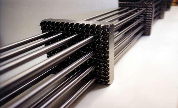
8 Fuel Production Route
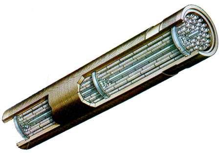
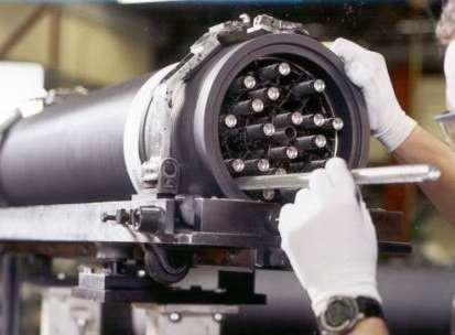
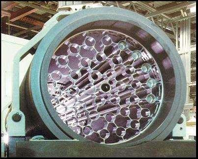
9 Components of Nuclear Fuel Nuclear fuel comprises of 2 essential components: 1. The fissile substance - usually U or one of its compounds 2. A metal cladding - to protect the fuel substance from the chemical environment and prevent fission gases escaping There are also additional fittings to hold the structures together, locate the fuel in the reactor or help with the loading and unloading
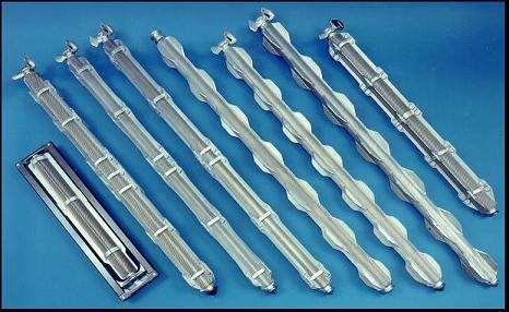
10 Fuel Types Two principal types of fuel are based on metal and oxide generally U, but MOX (Pu and U) or Th are alternatives Metal can be in the form of massive rods conveniently handled individually Oxide has much lower thermal conductivity formed into much thinner pins avoid unnecessary handling by building them into clusters ( assemblies, bundles etc) - can contain several hundred pins
11 UO 2 Fuel Production UO2 Gases to H.F. Recovery Turbo Sifter Autoclave Filters Steam Hydrogen Granulator Feed Hopper Uranium Hexafluoride (UF6) Vaporisation UF6 Cylinder Integrated Dry Route Rotary Kiln Drum Fill Blender Slugging Press Pressurising Pin/Pellet Assembly Inspection & Stack Build-up Pellet Grinding Storage & Inspection Sintering Furnace Pelleting Press Pin Leak Check Annealing Furnace Inspection Gamma Scanner Cleaning & Inspection Final Assembly Inspection & Despatch

12 Examples - Magnox and AGR


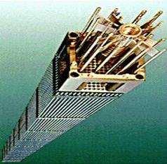
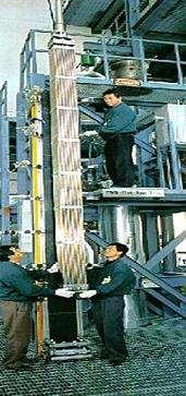
13 Examples - Light Water Reactor
14 Summary on Fuel Production Reactor demands govern how fuel is designed pin dimensions (heat transfer etc) fissile content (energy requirements) mechanical design (temps, radiation, chemical env.) Fuel design governs how fuel is manufactured pellets (physical and chemical properties) pins (integrity, materials used) elements (integrity, materials used) fissile material (throughputs, criticality control, dose control) Once the fuel has been manufactured into a suitable medium, it is then used in reactors and undergoes Irradiation
15 Irradiated fuel
16 Irradiated Fuel Irradiated fuel produces Fission products (FPs) Minor Actinides (MAs) Transuranics (TUs) Concentrations of each of these depend upon Reactor type Fuel type e.g. natural U, enriched UO 2, Pu etc Fuel burn-up Neutron energy spectrum Fuel age after discharge Spent fuel typically contains 96% U; 3% FPs and MAs (only 0.1%); 1% Pu Spent fuel is hot and intensely radioactive Requires cooling at reactor site prior to final destination

17 Irradiated Fuel Storage Storage provisions at Reactor site Reprocessing site Long term storage site Fuel store design considerations Criticality Operator shielding Heat dissipation Inventory management Fuel can then go on to Reprocessing Disposal Store
18 Wet vs. Dry Stores Ponds provide good heat transfer medium and cheap shielding (water) Water chemistry control is important avoidance of corrosion removal of activity Dry stores tend to require less intervention more suitable after some initial pond cooling
19 Reprocessing
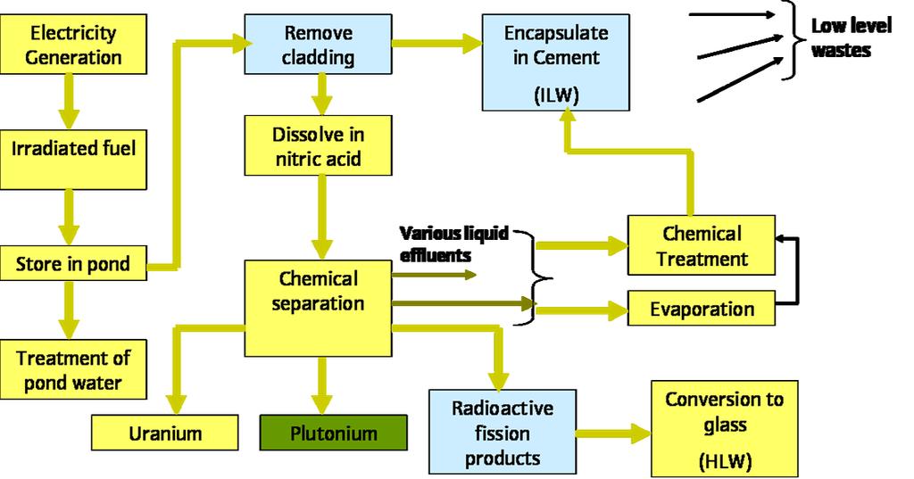
20 What is Reprocessing? Separation of Reusable Fissile Materials (U, Pu) for Recycle in New Nuclear Fuel. Essential step to close the nuclear fuel cycle Removal of fission product wastes for immobilisation and disposal A solvent extraction based process - the Purex process - is baseline industrial process Two Reprocessing Routes at Sellafield Magnox Reprocessing Thermal Oxide Reprocessing Plant (Thorp)
21 Reprocessing Why? National priorities Resource conservation - recycle of fissile materials Proliferation resistance /actinide burning Management of wastes /repository optimisation (cf. US experience) Spent fuel management: Build up of fission products and transmutation products Structure weakened and deformed by atomic displacement Fission gases pressurise fuel element In the case of Magnox, have to reprocess as cladding degrades with time when kept under water
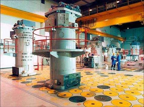
22 Sellafield Fuel Cycle Facilities

23 Waste Management
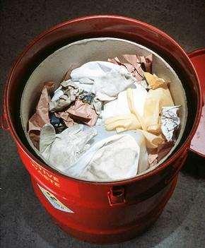
24 UK Waste Classification High Level Heat Generating Fission Products from reprocessing Intermediate Level Exceeds low level criteria Not significantly heat generating Low Level Emits very little radiation Clothing, paper etc worn/used by workers
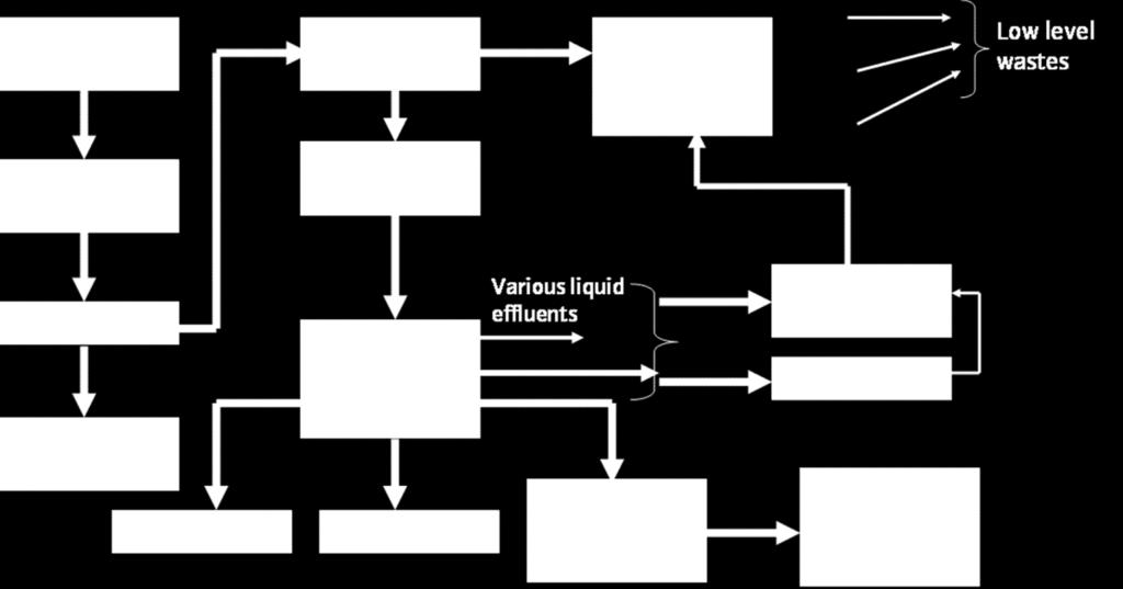
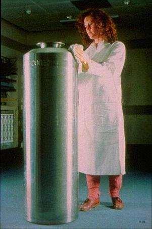
25 HLW Overview Includes Spent Fuel (if declared as waste) Storage to allow heat to decay Package Disposal in designated repository HLW separated from spent fuel during reprocessing Vitrification of waste Package Disposal in designated repository Highly Active Liquor (HAL) Storage Uncertainty over long term integrity of tanks (corrosion, settlement, possibility of hot spots) Requires active management Hence vitrification was adopted
26
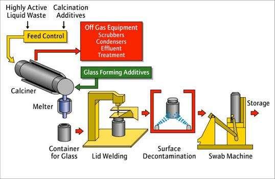
27 Vitrification The process
28 Sources of ILW Power Station Operations Fuel Element Debris, Filters, Sludges, Graphite Commercial Reprocessing Magnox de-splittering, Decanning, Magnox swarf, LWR hulls, LWR nozzles Plant Decommissioning Concrete, Cement, Rubble, Reactor Components (e.g. Control Rods), Graphite Fuel Fabrication and Enrichment Defence Medical and Industrial Sources


29 ILW is Cemented/Grouted Decommissioning Waste Magnox Swarf ILM Storage Currently stored awaiting repository
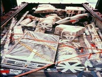
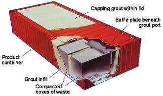
30 LLW Overview Sources include nuclear power stations, fuel cycle facilities, MoD, hospitals, Universities and other industries Low level waste disposed of in near-surface facilities for over 40 years. Mainly at the Drigg disposal site on the Cumbrian coast, some six kilometres to the south of the Sellafield nuclear reprocessing site. Disposals until the late 1980s were by tumble tipping essentially loose wastes into excavated trenches. More recently emplacement of containerised, conditioned wastes in concrete vaults.
31 Examples