Extremely low secondary electron emission from metal/dielectric particulate coatings
|
|
|
- Alvin Sanders
- 5 years ago
- Views:
Transcription


1 Utah State University Presentations Materials Physics Extremely low secondary electron emission from metal/dielectric particulate coatings Isabel Montero Instituto de Ciencia de Materiales de Madrid L Aguilera Instituto de Ciencia de Materiales de Madrid Leandro Olano Instituto de Ciencia de Materiales de Madrid María E. Dávila Instituto de Ciencia de Materiales de Madrid Luis Galán Instituto de Ciencia de Materiales de Madrid JR Dennison Utah State Univesity See next page for additional authors Follow this and additional works at: Part of the Condensed Matter Physics Commons Recommended Citation Montero, Isabel; Aguilera, L; Olano, Leandro; Dávila, María E.; Galán, Luis; Dennison, JR; and Wilson, Gregory, "Extremely low secondary electron emission from metal/dielectric particulate coatings" (2016). 14th Spacecraft Charging Technology Conference. Presentations. Paper This Presentation is brought to you for free and open access by the Materials Physics at DigitalCommons@USU. It has been accepted for inclusion in Presentations by an authorized administrator of DigitalCommons@USU. For more information, please contact dylan.burns@usu.edu.
2 Authors Isabel Montero, L Aguilera, Leandro Olano, María E. Dávila, Luis Galán, JR Dennison, and Gregory Wilson This presentation is available at DigitalCommons@USU:

3 14 th Spacecraft Charging Technology Conference Space Research and Technology Centre of the European Space Agency (ESA/ESTEC) Noordwijk, The Netherlands April 4-8, 2016 Extremely low secondary electron emission from metal/dielectric particulate coatings I.Montero, L.Aguilera, L.Olano, M.E.Dávila, Instituto de Ciencia de Materiales de Madrid. CSIC Madrid. Spain V.Nistor, L.Galán Applied Physics Dep., UAM J.R. Dennison, G. Wilson Materials Physics Group, Utah State University, Logan, Utah, 84322, USA
4 CONTENT Main goals Introduction: Antimultipactor coatings Antimultipactor coatings for ESA Micrometric dielectric particulate coatings Extremely low secondary electron emission from metal/dielectric particulate coatings SEY simple theoretical model Conclusions

5 Main goals To mitigate: 1.The multipactor effect in space-relate highpower RF hardware 2.The electron cloud and its adverse consequences
6 Main goals Multipactor phenomenon characteristics Weak discharge Secondary electron emission seed and feedback (avalanche) Only ocurring under vacuum conditions Threatening any RF component Can cause disturbances/degradation of onboard satellite equipment and even total loss of the mission
7 Introduction I p = I + I s I > 0, I p < 0 I s is measured in the sample I p is measured in the Faraday cup V g e-beam sample collector e-gun cathode electrometers I s -I σ V c collector connected to ground,
8 Introduction Development of coatings with low secondary electron emission yield (SEY)
9 Introduction Main objectives: Very low SEY like Au / roughag max < 1.5 E 1 > 200 ev Very low RF surface resistance close to Ag < 1.5 x R surf (Ag) Tesat en ITI Very slow aging in air > one year
10 Introduction Secondary Emission Suppression by Surface Roughness of High Aspect Ratio w h Roughness: aspect ratio porosity Low SEY Sample in each generation secondary energy decreases High E 1 value High stability in air Ag, Au, High conductivity Ag Varias pequeñas modificaciones
11 Introduction Anti-Multipactor Coatings Deposition Methods Gas (UHV) Liquid Solid Physical Vapor Deposition Evaporation Ion implantation and/or reaction Sputtering Chemical Methods Chemical Etching or Growth Anodization Particles Deposition Varias pequeñas modificaciones


12 Introduction ANTI MULTIPACTOR COATINGS Au 2 µm DIFFERENT KINDS TESTED ROUGH NEG CHEMICAL ETCHING aluminium Etched aluminium Silver etched Nickel Aluminum Gold-coated etched silver NEG-coated etched Al 1µm R r /R s = 12 GHz
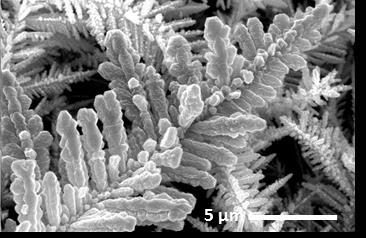
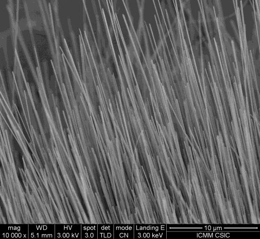
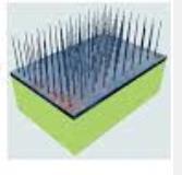
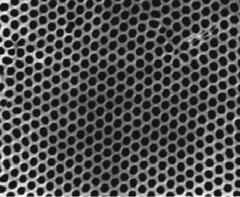
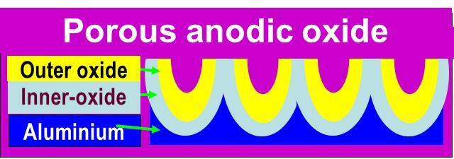
13 Introduction ANTI MULTIPACTOR COATINGS DIFFERENT KINDS TESTED Ag microstructured Nanoporous templates CuO nanowires Cu Cu Cu
 10 3 aspect ratio T=")
14 SEY Introduction CuO nanowires 2,5 2,0 1,5 1,0 0,5 0,0 Cu liso CuO 500ºC-2h CuO 500ºC-8h CuO sin NW CuO 500ºC-4h CuO 500ºC-10h CuO 1h CuO 500ºC-6h Primary Electron Energy (ev) 10 3 aspect ratio T= 500ºC,

15 Antimultipactor coatings for ESA DEFINITION OF SAMPLES Harmonic low-pass corrugated filters = Multipactor samples for low-power RF behaviour and multipactor threshold tests as received Ag plating treated filter RF filter rectangular crossing grooves in corrugated central part K band GHz
16 Antimultipactor coatings for ESA Microstructured silver

17 Antimultipactor coatings for ESA THE CHEMICAL TECHNIQUE PATENT CSIC, TESAT, ESA

18 Antimultipactor coatings for ESA SEY curves of treated filter SEY < 1 PATENT CSIC, TESAT, ESA
19 SEE coefficient Micrometric dielectric particulate coatings SEE coefficient Micrometrical Al 2 O 3 Particles Coating From suspension of nanometrical Al 2 O 3 particles Aluminum alloy substrate Al 2 O Indentation of micrometrical ceramic particles Aluminum alloy substrate 25 nm Au coating (continuous) as prepared (pulse) nm Au coating (pulse) continuous technique pulse technique Primary Electron Energy [ev] Primary Electron Energy [ev]
20 Micrometric dielectric particles coatings Extremely low secondary electron emission from metal/dielectric particulate coatings Metallic/Dielectric MicroParticle Mixture Irregular shape Al particle Al 2 O 3 particle 25% Al 2 O 3 50% Al 2 O 3 75% Al 2 O 3 Surface top view
21 SEY coefficient Micrometric metal/dielectric particles coatings Extremely low secondary electron emission from metal/dielectric particulate coatings 2,0 1,8 1,6 1,4 1,2 1,0 0,8 0,6 0,4 0,2 0,0 SEY Al2O3 75%+Al 25%+Au Al2O3 50%+ Al 50% +Au Al2O3 25%+ Al 25% +Au 25% Al 2 O 3 50% Al 2 O 3 75% Al 2 O Primary Electron Energy (ev) SEY values close to 0 Isabel Montero AEC 09 CERN
22 Micrometric metal/dielectric particles coatings Extremely low secondary electron emission from metal/dielectric particulate coatings SEY Theoretical Model a simple atempt for explaining
23 Micrometric metal/dielectric particles coatings SEY Secondary electron emission yield (SEY) p SEY = - I /I p I = I + I + I E 1 δ sample ε η Primary energy EDC, Energy Distribution Curves I Ep
24 V e-gun sample I o Micrometric metal/dielectric particles coatings cathode Sample current technique for SEY test I V s V b eff I 1 I o I o = I + I m During calibration with a Faraday cup (I = 0), I o is measured in the pico-amp meter. I I The apparent primary energy is: E p = V b V e-gun (in units of ev and V) m o I m meter The real primary energy is: E o = V s V e-gun. In a perfect conductive sample V s = V b eff (E o, V s ) = eff (E o, V s ) + eff (E o, V s ) + (E o )
25 The Cumulative Probability Functions (MEST) where 75,0.3} min{ 1.5 o o s E E X and n s = 0.65, = 5 ev are material dependent constants (X max /E o ). For the true secondary electron emission: ) 2 tan( 2 tan arctan 2 ) ( 2 s n s X X X F s For the inelastically backscattered secondary electron emission: b b b n b n n b b X X X X F cos 1 cos 1 where n b = 1.5 and X b = (2 1/nb X max ) = 0.85 are material dependent constants Micrometric metal/dielectric particles coatings
26 Micrometric metal/dielectric particles coatings The condition of stationary or dc SEY measurement is: eff (V s ) 1 = I m / I o = ( I o R o ) 1 (1+ V sample2 ) V sample Explain atypical SEY: to solve this equation, i.e., to find the possible values of E p and V sample solutions of this equation, with eff 1 < 0, I m < 0, and V sample < 0 (V sample > 0 and I m < 0 is not possible)
27 Micrometric metal/dielectric particles coatings SEY, sample current Two solutions for a certain wide primary energy (E p ) range above the first cross-over energy E 1 2 SEE of High Resistance Coating 1,5 1 EMISS Im/Io EMISS-1 ATYPICAL 0,5 0 NORMAL -0,5-1 -1, Vs [V] Secondary electron emission as a function of sample voltage, for E p = 400 ev. EMISS = σ eff
28 effective coefficient Micrometric metal/dielectric particles coatings 2 1,8 1,6 1,4 1,2 1 0,8 0,6 0,4 0,2 0 The atypical solution with eff < 1, V s < 0, and E o decreasing from E 1 to values close to Ee-gun [ev] Evolution of effective SEY in an iterative procedure with ΔV sample = k (σ eff 1 (I m / I o )) Convergence to σ eff < 1 in a energy range ev. SEY SEY EMISS 1 EMISS 2 EMISS 2 EMISS 3 EMISS 4 EMISS 5 EMISS 6 EMISS 7 EMISS 8 EMISS 9 EMISS 10 EMISS 11 EMISS 12 EMISS 13 EMISS 14 EMISS 15
29 effective coefficient Micrometric metal/dielectric particles coatings 2 1,8 1,6 1,4 1,2 1 0,8 0,6 0,4 0,2 0 The atypical solution with eff < 1, V s < 0, and E o decreasing from E 1 to values close to Ee-gun [ev] Evolution of effective SEY in an iterative procedure with ΔV sample = k (σ eff 1 (I m / I o )) Convergence to σ eff < 1 in a energy range ev. Above this wide energy range with two solutions, only the normal one, eff = 1+, is always possible. SEY SEY EMISS 1 EMISS 2 EMISS 2 EMISS 3 EMISS 4 EMISS 5 EMISS 6 EMISS 7 EMISS 8 EMISS 9 EMISS 10 EMISS 11 EMISS 12 EMISS 13 EMISS 14 EMISS 15
30 e Impacting Energy, Surface Potential Micrometric metal/dielectric particles coatings 2500 SEE of High Resistance Coating Eo Vs E e-gun [ev, V] Real primary energy and surface potential of the high resistance coating as determined by Solver of Excel
31 Intensity 0,1 0,09 Micrometric metal/dielectric particles coatings Energy Distribution Curves, EDC EDC conductor Elastic peak determined by e-gun energy Secondary electron peak shifted by bias voltage EDCdelta EDCeta 0,08 0,07 0,06 EDCeps EDCsigma 0,05 0,04 0,03 0,02 0, Energy
32 Intensity Energy Distribution Curves, EDC 0,1 Micrometrical metal/dielectric particles coatings EDC normal dielectric EDCdelta 0,09 0,08 0,07 0,06 0,05 0,04 0,03 0,02 0,01 Elastic peak determined by e-gun energy Secondary electron peak shifted below cero by sample charging voltage Part of secondary electron peak suppressed EDCeta EDCeps EDCsigma Energy
33 Intensity 0,1 Micrometric metal/dielectric particles coatings Energy Distribution Curves, EDC EDC atypical dielectric EDCdelta 0,09 0,08 0,07 0,06 0,05 0,04 0,03 0,02 0,01 Elastic peak determined by e-gun energy Secondary electron peak shifted by sample charging voltage EDCeta EDCeps EDCsigma Energy
34 Conclusions MAIN CONCLUSIONS: Coatings of micrometric surface roughness can avoid Multipactor effect. SEY of metal/dielectric particulate coatings can be lower than 0.2 until Ep of the order of 1000 ev. The extreme decrease of SEY of metal/dielectric particulate coatings could be explained by using a simple model: Two different solutions were found: the normal and the atypical one with extremely low-sey values Why the atypical one is chosen by metal/dielectric particulate coatings?
35 THANK YOU FOR YOUR ATTENTION