Module 11 High Temperature Gas Cooled Reactors (HTR)
|
|
|
- Melvin Barber
- 5 years ago
- Views:
Transcription


1 Prof.Dr. H. Böck Atominstitute of the Austrian Universities Stadionallee 2, 1020 Vienna, Austria Module 11 High Temperature Gas Cooled Reactors (HTR)

 1967-1974 FORT ST. VRAIN (U.S.A.) 1976-1989 THTR (FRG) 1986-1989")
2 Development of Helium Reactor Technology From 1963 to 1989 DRAGON (U.K.) AVR (FRG) PEACH BOTTOM 1 (U.S.A.) FORT ST. VRAIN (U.S.A.) THTR (FRG)
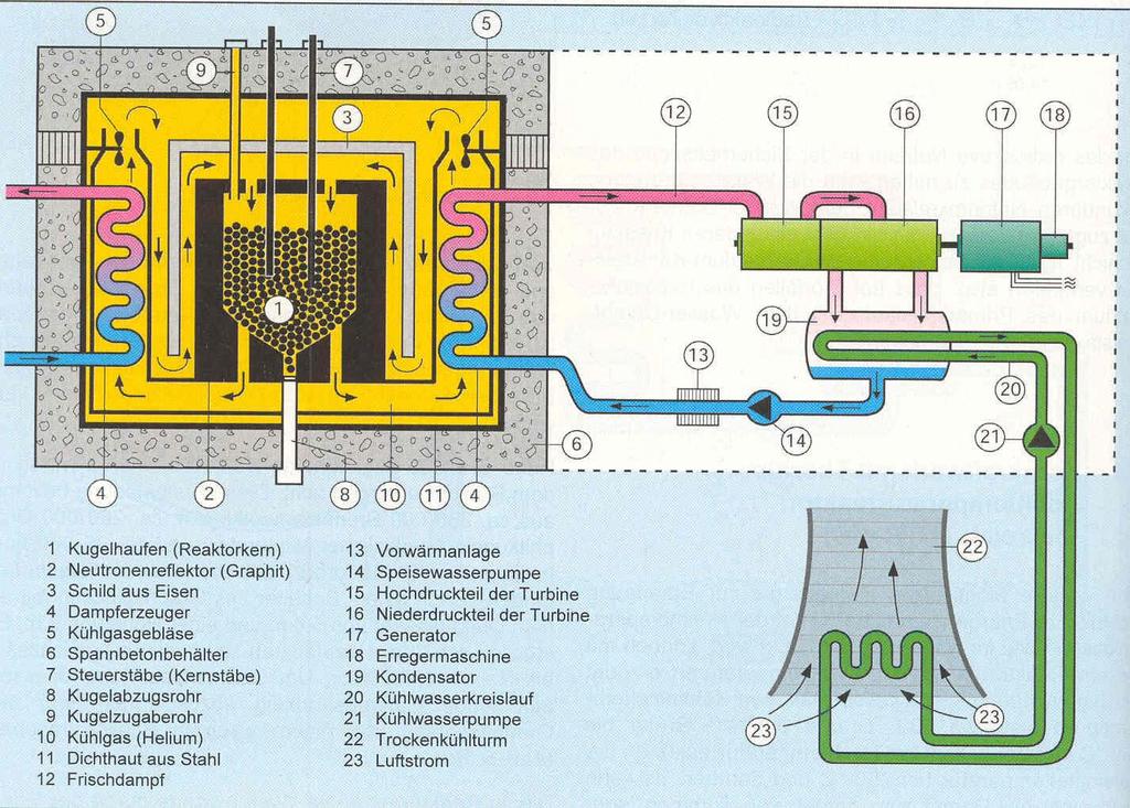
3 Technical Background 1 For higher thermal efficiency higher gas temperatures up to 1000ºC are necessary CO 2 gas temperature is limited to 800ºC then it disintegrates into C and O Only stable gas with good nuclear and thermal properties is Helium No activation Chemically inert High specific heat Stable to high temperatures
4 Technical Background 2 For HTR no metallic fuel cladding possible Only solution is high density graphite Low neutron absorption Minimal radiation damage Superb heat resistance High thermal conductivity Therefore development of new fuel types - coated particles embedded in graphite Two major lines: 1. Graphite fuel spheres (pebbles): German version 2. Graphite prismatic fuel assemblies: US version
5 Advantages of HTR High efficiency: 47% Possibility of U-233 breeding from Th-232 Excellent passive safety features Strong negative temperature coefficient Excellent fission product retention Simple design Economically attractive Burn-up of MWd/ton
6 International Activities 1 Germany: 15 MW e AVR operated first HTR from 1967 to 1988, followed by 300 MW e Thorium-Hochtemperaturreaktor THTR (Pebble Bed Reactor) operated between 1986 to 1989 German development was stopped in the late 80-ties, but German industry cooperates with South Africa, China, Indonesia and Russia on modular units of Pebble Bed Modular Reactors (PBMR)
7
8 International Activities 2 South Africa plans 165 MW th PBMR between after 2012 China operates a 10 MW th (2 MW e prototype PBMR, critical since 2000 Japan works on a 40 MW th PBMR with prismatic fuel assemblies Russia plans a 330 MW e Pu Burner with prismatic fuel assemblies for 2012

9 High Temperature Pebble Bed Modular Reactor (PBMR) 360,000 pebbles in core About 3,000 pebbles handled by fuel handling system each day About 350 discharged daily One pebble discharged every 30 seconds Average pebble cycles through core 15 times Burn-up of MWd/t Fuel handling most maintenance-intensive part
10 Typical PBMR Technical Data 110 MW e Helium Cooled Indirect Cycle 8% Enriched Fuel Built in 2 Years Factory Built Site Assembled On-line Refueling Modules added to meet demand - no Reprocessing High Burn-up >90,000 MWd/t Direct Disposal of High Level Waste
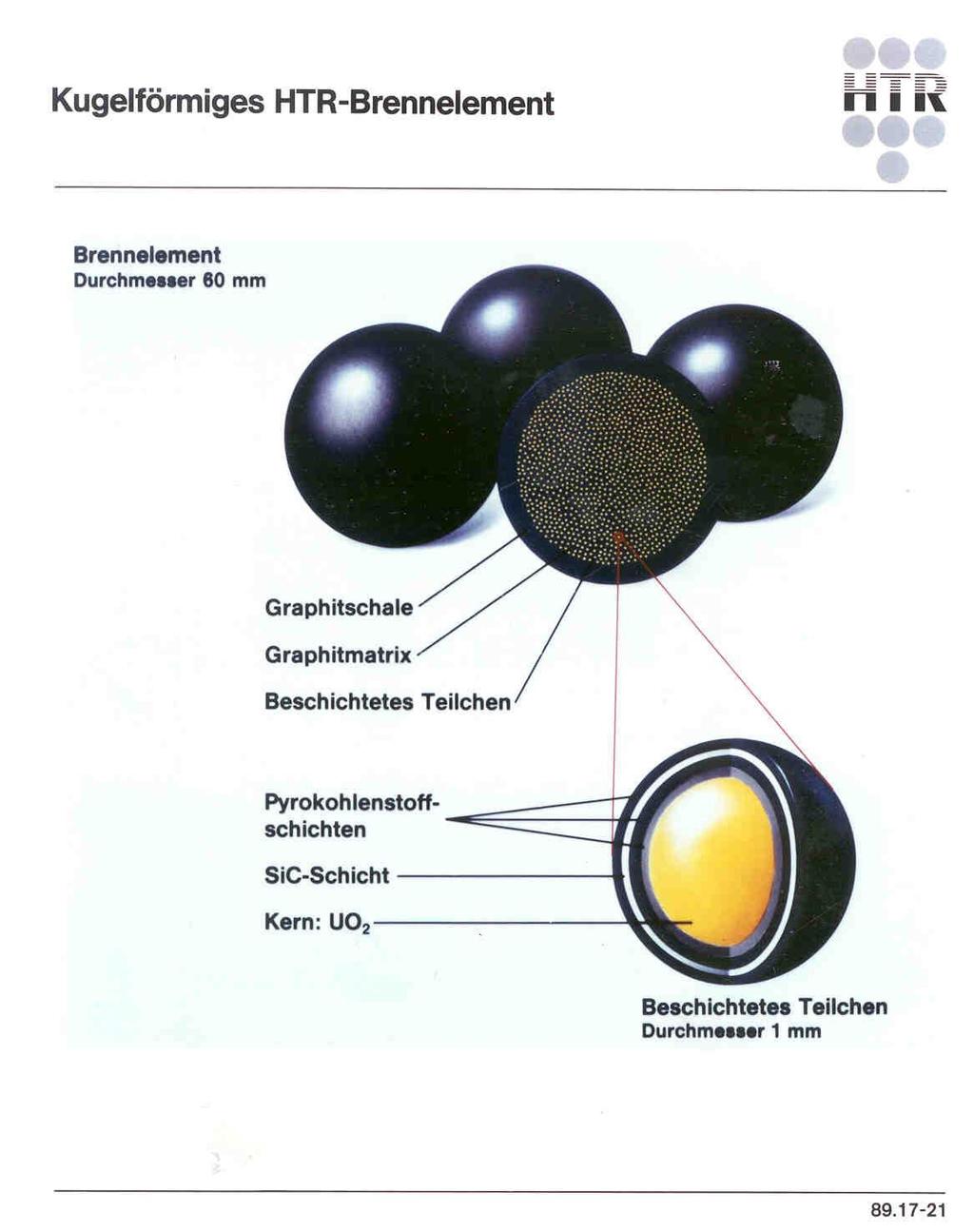
11 PBMR Fuel Spheres Fuel particles (kernels) consist of uranium dioxide Coated particles embedded in a spherical graphite matrix, 50 mm diameter 5 mm thick fuel-free outer graphite zone, overall outer sphere diameter 60 mm One fuel sphere contains approximately coated particles fuel spheres are required for a single core loading

12 Composition of Graphite Spheres FUEL ELEMENT DESIGN FOR PBMR 5mm Graphite layer Coated particles imbedded in Graphite Matrix Dia. 60mm Fuel Sphere Pyrolytic Carbon 40/1000mm Silicon Carbite Barrier Coating Inner Pyrolytic Carbon 40/1000mm Porous Carbon Buffer 95/1000mm 35/1000mm Half Section Dia. 0,92mm Coated Particle Dia.0,5mm Uranium Dioxide Fuel

13 Construction of Graphite Spheres

14 Ceramic Coated Fuel Particles

15 Microcut through Fuel Kernel

16 Production of Coated Particles


17 TRISO Fuel Particle Microsphere Pyrolytic carbon: Material similar to graphite with some covalent bonding between it layers Produced by heating CH 4 nearly to its breakdown temperature and permitting the graphite to crystallise on the UO 2 kernels
18 Fuel Sphere Production 1 Solution containing 8% enriched uranium is cast to form microspheres. These are washed, calcinated and sintered at high temperature to produce uranium dioxide kernels Kernels are then put in a Chemical Vapour Deposition furnace at a temperature above 1000ºC in which the pyrolytic carbon coating layers are added with extreme precision by cracking CH 4 into C+H SiC-layers have different densities: -one inner layer low density to capture volatile fission products, -two outer layers with high density
19 Fuel Sphere Production 2 Carbon densities can be adjusted by cracking temperature and exposure time The coated particles with about a millimeter in diameter are mixed with a resin and graphite powder and pressed into 50mm diameter spheres A 5mm thick layer of fuel free graphite powder is then added to form the "fuelfree" outer zone. The resulting spheres are then machined, carbonized and annealed
20 TRISO Fuel Particle (Kernels) Microsphere 0.9 mm diameter ~11,000 particles in every pebble Fission products retained inside microsphere TRISO acts as a pressure vessel (= first and second barrier) Reliability Defective coatings during manufacture ~1 defect in particles

21 Cross Section of the German 300 MWeTHTR Core operating from 1983 to 1988

22 THTR Core during loading procedure

23 US Fort Saint Vrain HTR

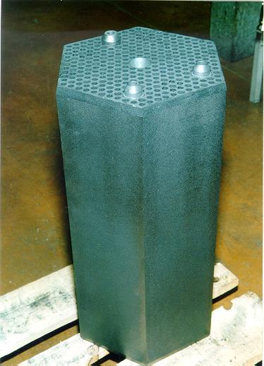
24 US Prismatic Fuel
25 China s HTR Programme In February 2006, the State Council announced that the small high-temperature gas-cooled reactor (HTR) was the second of two high priority projects for the next 15 years. The small HTR-PM units with pebble bed fuel were to be 200 MWe reactors, similar to that being developed in South Africa Plans have evolved to make them twin 105 MWe units driving a single steam turbine.

26 Reactor Building of China s HTR-10
27 HTR-10 ATW 12/ decision to construct HTR construction started after safety review December 2000 first criticality January 2003 full power operation Excellent operation record Used for reactor safety experiments during normal and abnormal operation
![Operational Data of the HTR-10 ATW 12/2006 Design Operation Nuclear power [MW] 10 10.3 Electric power [MW] 2.5 2.2 Helium inlet temperature [ 0 C] 250 237.4 Helium outlet temperature [ 0 C] 700 700.](/docs-images/85/91694944/images/28-2.jpg "2 Helium pressure [MPa] 3 3 Feed water temperature [ 0 C] 104 100 Steam temperature [ 0 C] 435 433 Feed water flow [kg/s] 3.48 3,57 Steam pressure [MPa] 3.5 3.")
28 Operational Data of the HTR-10 ATW 12/2006 Design Operation Nuclear power [MW] Electric power [MW] Helium inlet temperature [ 0 C] Helium outlet temperature [ 0 C] Helium pressure [MPa] 3 3 Feed water temperature [ 0 C] Steam temperature [ 0 C] Feed water flow [kg/s] ,57 Steam pressure [MPa] Fuel number [-] 13,622 Graphite spheres number [-] 16,387

29 Chinese Modular HTR Modular Pebble Bed HTR Power 10 MWth Core : pebbles diameter 1,8m approximative height 2m Construction 1995 Criticality 1/12/ / Passive Decay Heat Removal

30 Core of HTR-10
31 Passive Safety Feature in Case of LOCA Fuel temperatures remain below design limits even during loss of cooling
32 Temp ( C) Loss of Coolant Flow Temperature well below design limits 265 MW PBMR Ref. Core: Temperature Distribution during a DLOFC 1600 Maximum Fuel Temperature Average Fuel Temperature Maximum RPV Temperature Average RPV Temperature Time (h)
33 Chinese Pebble Bed-HTR PM 200 MWe demonstration unit at Weihei/Shandong province Later 18 modules of full-scale power Project costs US 375 M$ Start-up in fuel elements, 9% enriched Low power density but high temperature 900 C 60 years life time, 85% availability First of 18 modules
![Parameters of the HTR_Pebble Bed Module (HTR-PM) ATW 12/2006 Reactor thermal power [MW] Electric](/docs-images/85/91694944/images/34-2.jpg "power [MW] 458 MW 195 MW Fuel number at equilibrium core [-] 520,00 Core Heigh/out diameter/inner")
![diameter [m] 11/ 4 / 2.](/docs-images/85/91694944/images/34-3.jpg "2 Helium pressure [MPa] 9 Helium flow rate [kg/s] 176 Helium temperature inlet/outlet [ 0 C] 250/750")
34 Parameters of the HTR_Pebble Bed Module (HTR-PM) ATW 12/2006 Reactor thermal power [MW] Electric power [MW] 458 MW 195 MW Fuel number at equilibrium core [-] 520,00 Core Heigh/out diameter/inner diameter [m] 11/ 4 / 2.2 Helium pressure [MPa] 9 Helium flow rate [kg/s] 176 Helium temperature inlet/outlet [ 0 C] 250/750 Steam flow rate [t/h] Steam temperature [ 0 C] 538 Steam temperature [MPa] 13.5
35 Mock-up of Chinese HTR-Plant (3600 MWe) in Shangdon HTR Module construction started on Jan 7th Costs approx 360, operational end of 2017 First of 18 HTR Modules plus 4 PWR at that site NUCNET 3/2013
36 References Atomwirtschaft 2011 p.344: Die Technologie des HTR zur Erzeugung flüssiger Brennstoffe, Wasserstoff und elektrische Energie