CE 240 Soil Mechanics & Foundations Lecture 4.3. Permeability I (Das, Ch. 6)
|
|
|
- Bertina Ferguson
- 5 years ago
- Views:
Transcription
1 CE 240 Soil Mechanics & Foundations Lecture 4.3 Permeability I (Das, Ch. 6)
2 Outline of this Lecture 1. Permeability in Soils 2. Bernoulli s Equation 3. Darcy s Law 4. Hydraulic Conductivity 5. Hydraulic Conductivity Tests

3 Due to the existence of the inter-connected voids, soils are permeable. The permeable soils will allow water flow from points of high energy to points of low energy. Permeability is the parameter to characterize the ability of soil to transport water.
4 Permeability in Soils Permeability is the measure of the soil s ability to permit water to flow through its pores or voids It is one of the most important soil properties of interest to geotechnical engineers
5 Soil Permeability Soil Properties Physical (Soil Characteristics) Mechanical Specific Gravity Gradation Atterberg Limits Compaction Permeability Compressibility Strength (Shear) Moisture Content Unit Weight 1 Constant-Head Test 2 Falling-Head Test
6 Importance of permeability The following applications illustrate the importance of permeability in geotechnical design: Permeability influences the rate of settlement of a saturated soil under load. The design of earth dams is very much based upon the permeability of the soils used. The stability of slopes and retaining structures can be greatly affected by the permeability of the soils involved. Filters made of soils are designed based upon their permeability.
7 Use of Permeability Knowledge of the permeability properties of soil is necessary to: Estimating the quantity of underground seepage (Chapter 7); Solving problems involving pumping seepage water from construction excavation; Stability analyses of earth structures and earth retaining walls subjected to seepage forces.
8 Bernoulli s equation The total pressure in terms of water head is formed from 3 parts: 1), pressure head; 2), dynamic head; and 3), elevation head. This is known as the Bernoulli s equation: 2 h P v = + + γ 2g w h: total head in m, or ft; P: water pressure in Pa, or psi; γ w : unit weight of water, in kg/(s 2 m 2 ), or lb/(ft 3 ); v: velocity of water, in m/s, or ft/s; g: gravity acceleration m/s 2 or ft/s 2 ; Z: elevation head in m, or ft. Z
9 The surface of the water column (the head) is the water table. Water Table in an Unconfined Aquifer is the surface along which the hydrostatic pressure is equal to the atmospheric pressure. Atmospheric pressure
10 Confined Aquifer: Water in confined aquifer is separated from air by impermeable layers known as aquiclude. This type of aquifer forms an artesian system; The well drilling into confined aquifer then could be an artesian well (the water level in the well is above the height of the ceiling aquiclude). Piezometric surface Ceiling aquiclude Floor aquiclude
11 datum The dynamic head is usually negligible since the water flow velocity is usually small. The elevation head is accounted from the datum to the elevation of the bottom of the well, and the pressure head is the portion above the well bottom to the water table. Piezometric surface Pressure head P/γ w Elevation head Z
 can")

12 Again, since the seepage flow velocity in soil is small, the dynamic head (velocity head) can be neglected, so that the total head at any points is h P = + Z γ w Hydraulic gradient: h i = L

13 may exist in fractured rock, stones, gravels, and very coarse sands in most soil we found the following relation, i.e., the water flow velocity in the soil is proportional to the hydraulic gradient v i
 k =")
14 Darcy s Law The coefficient of permeability, or hydraulic conductivity, k, is a product of Darcy s Law. In 1856, Darcy established an empirical relationship for the flow of water through porous media known as Darcy s Law, which states: v = v = -ki or q = -kia q = flow rate (cm 3 /s) k = coefficient of permeability (cm/s) A = cross-sectional Area (cm 2 ) i = hydraulic gradient
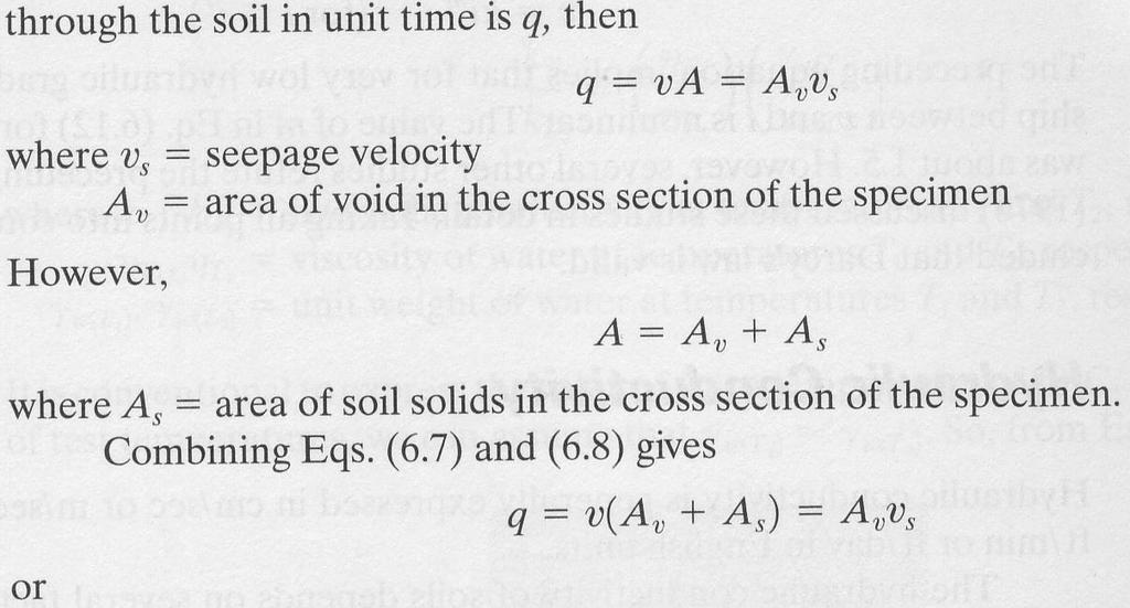
15 The parameter q in Darcy s law is called the flow rate or simply the flow (flux). It describes in a unit time, over a unit cross-section area, how much water in terms of volume has been flowed through. volume length q= va, ( = area) time time The flow rate q is in the unit of velocity (L/t). Examination of the Darcy s law make us be aware that the permeability k is also in the unit of velocity. v A


16 Velocity and seepage velocity
17 in the field, the gradient of the head is the head difference over the distance separating the 2 wells. dh v= k = k dx H H 2 1 x Water flow H 1 H 2 x
18 Darcy s law states that how fast the groundwater flow in the aquifer depends on two parameters: 1, how large is the hydraulic gradient of the water head (i=dh/dx); and 2, the parameter describing how permeable the aquifer porous medium the coefficient of permeability (hydraulic conductivity) k. The minus sign in the equation denotes that the direction of flow is opposite to the positive direction of the gradient of the head.
19 The physical description of groundwater flow in soil is the Darcy s law. The fundamental premise for Darcy s law to work are: 1, the flow is laminar, no turbulent flows; 2, fully saturated; 3, the flow is in steady state, no temporal variation.
20 Hydraulic conductivity k and absolute permeability K The absolute permeability is in the unite of LL (length square); and the expression for the relation is k = γ w η K
21 Units of the coefficient of Permeability k The permeability k is in the dimension of velocity. However, in deferent field people prefer use different units for permeability simply because different fields deal different scales of subsurface fluid flow. In hydrogeology a used to be popular unit is meinzer; in geotechnical world is cm/sec; and in petroleum engineering people just use the unit of darcy. Here are the conversions: 1 cm/sec = 864 m/day 1 darcy = 1 cm 3 of fluid with viscosity of 1 centipose in 1 sec, under a pressure change of 1 atm. over a length of 1 cm through a porous medium of 1 cm 2 in cross-sectional area. 1 Meinzer = 1gal/day/ft 2
")
22 (West, 1995)
23 Hydraulic Conductivity The coefficient or permeability is also known as hydraulic conductivity; Hydraulic Conductivity, k, is a measure of soil permeability; k is determined in the lab using two methods: Constant-Head Test Falling-Head Test
24 Hydraulic Conductivity (Cont.) Hydraulic conductivity of soils depends on several factors: Fluid viscosity Pore size distribution Grain size distribution Void ratio Degree of soil saturation
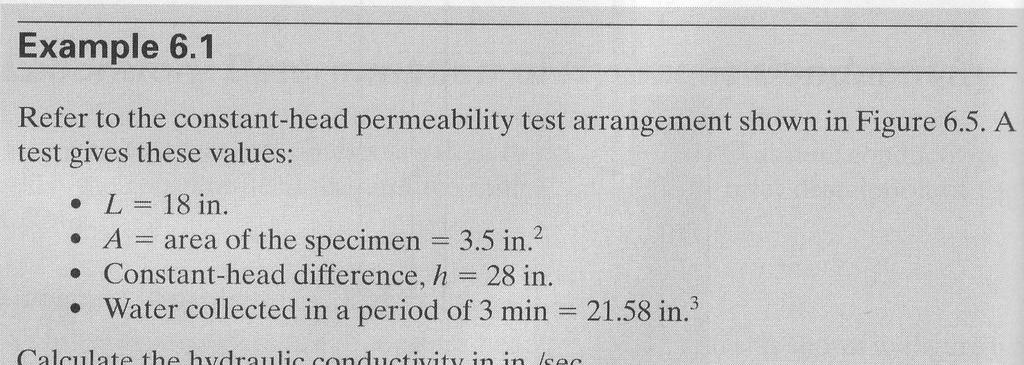
25 Constant Head Test The constant head test is used primarily for coarse-grained soils; This test is based on the assumption of laminar flow where k is independent of i (low values of i); ASTM D 2434; This test applies a constant head of water to each end of a soil in a permeameter.
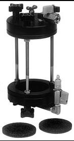
26 Permeameter


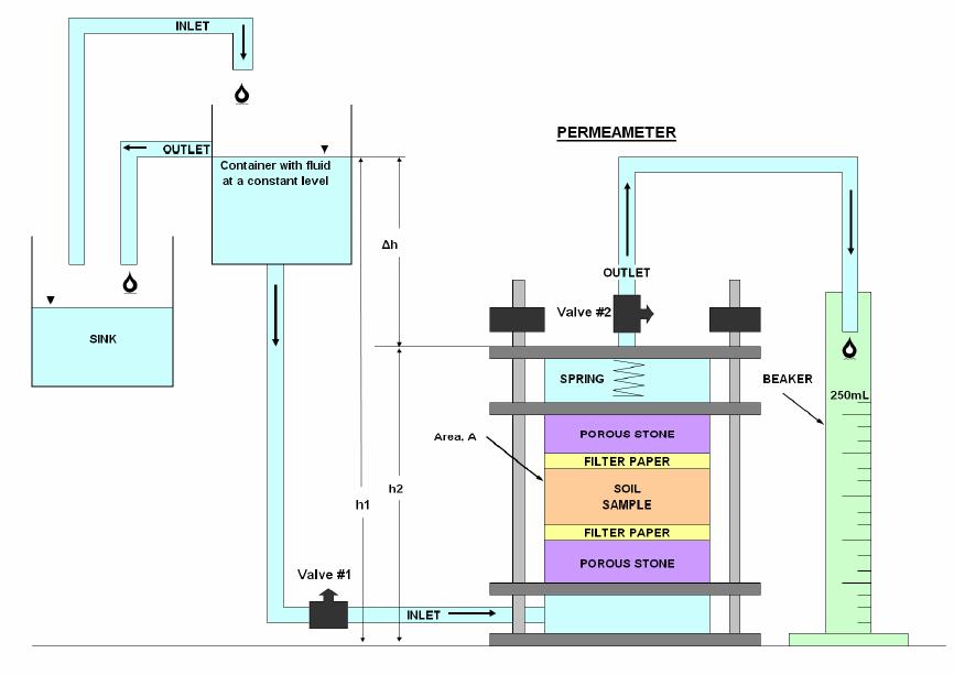
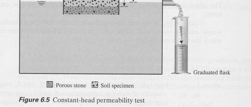
27 Constant-head hydraulic conductivity test with permeameter
28
t")
29 Q = Avt = A(ki )t
30 Procedure (Constant head) 1. Setup screens on the permeameter 2. Measurements for permeameter, (D), (L), H1 3. Take 1000 g passing No.4 soil (M1) 4. Take a sample for M.C. 5. Assemble the permeameter make sure seals are air-tight 6. Fill the mold in several layers and compact it as prescribed. 7. Put top porous stone and measure H2 8. Weigh remainder of soil (M2) 9. Complete assembling the permeameter. (keep outlet valve closed) 10.Connect Manometer tubes, but keep the valves closed. 11.Apply vacuum to remove air for 15 minutes (through inlet tube at top) 12.Run the Test (follow instructions in the lab manual).. 13.Take readings Manometer heads h1 & h2 Collect water at the outlet, Q ml at time t 60 sec.
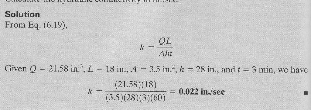
31 Calculation (Constant head) Determine the unit weight; Calculate the void ratio of the compacted specimen; h from Q = Akit = A( k ) t Calculate k as: L QL get k = Calculate Aht k = k T 0 C η 0 20 C η T 0 C 0 20 C
32
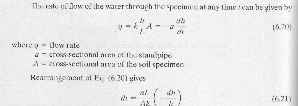
33 Falling Head Test The falling head test is used both for coarse-grained soils as well as finegrained soils; Same procedure in constant head test except: Record initial head difference, h 1 at t = 0 Allow water to flow through the soil specimen Record the final head difference, h 2 at time t = t 2 Collect water at the outlet, Q (in ml) at time t 60 sec
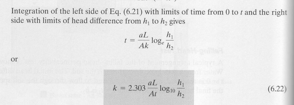
34 Calculation (Falling head) Calculate k as Where: A = inside cross sectional area of the water tank a = inside cross sectional area of the standing pipe h 1 = distance to bottom of the beaker before the test h 2 = distance to bottom of the beaker after the test Calculate k k = = k T 0 C al At η 0 20 C η ln h h 1 T C C 2

35 Falling Head Test
36

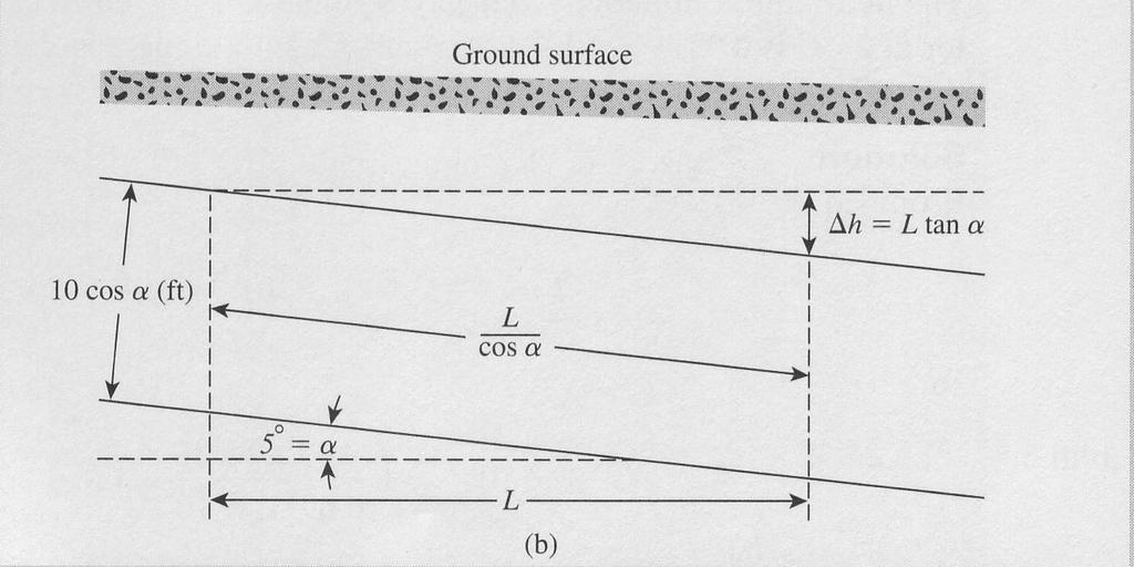
37 Example 6.4 Figure 6.7
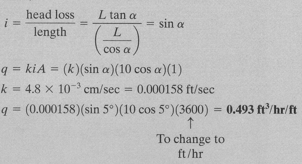
38

39 Example 6.5 Figure 6.8
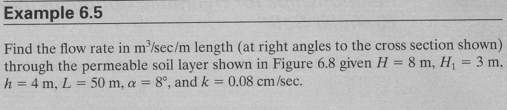
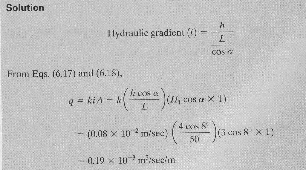
40
41 Reading Assignment: Das, Ch. 6 Homework: 6.3, 6.4, 6.7, 6.8, 6.12