WASTEWATER TREATMENT (1)
|
|
|
- Silas Greer
- 5 years ago
- Views:
Transcription
1 Wastewater Engineering (MSc program) WASTEWATER TREATMENT (1) Prepared by Dr.Khaled Zaher Assistant Professor, Public Works Engineering Department, Faculty of Engineering, Cairo University
2 Wastewater Flow Diagram Inlet Chamber Screening Grit Removal Primary Sedimentation Primary Sludge Biological Treatment Final Sedimentation Secondary Sludge Final Disposal
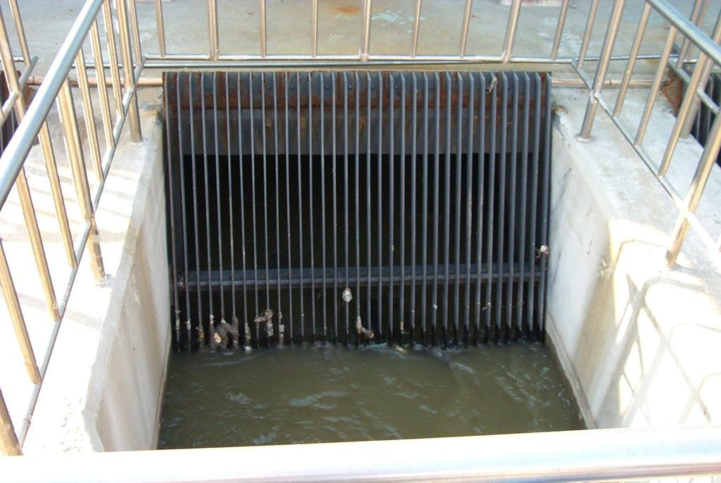
3 1. Screening 3 A screen is a device with openings, generally of uniform size, that is used to retain solids found in the influent wastewater to the treatment plant. The principle role of screening is to remove coarse materials from the flow stream that could: 1. damage subsequent process equipment 2. reduce overall treatment process reliability and effectiveness 3. contaminate waterways Fine screens are sometimes used in place of or following coarse screens where greater removals of solids are required (1) protect process equipment or (2) eliminate materials that may inhibit the beneficial reuse of biosolids.
4 4 The screening element may consist of parallel bars, rods or wires, wire mesh, or perforated plate, and the openings may be of any shape but generally are circular or rectangular slots. A screen composed of parallel bars or rods is often called a ''bar rack'' or a coarse screen and is used for removal of coarse solids. The materials removed by these devices are known as screenings. Hand cleaned coarse screens are used when the flow is not more than 5000 m 3 /d, while mechanical cleaned coarse screens are used when the flow is more than 5000 m 3 /d.
5 5
6 6
7 7 Design criteria according to Egyptian code: Horizontal velocity through clean bar screens = m/s component of horizontal velocity perpendicular to screen 0.6 m/s Distance between bars of fine screen = 25 mm - 50 mm Distance between bars of coarse screen = 25 mm - 75 mm Inclined angle of hand cleaned coarse screens = 45 o - 60 o Inclined angle of mechanical cleaned coarse screens = 60 o - 80 o Width of one bar = 1-2 cm Length of one bar = 2-6 cm Diameter of one bar = cm
8 8 To design a coarse screen: Q = A * V V = V *sin θ A = area = ((n-1)*s) * d W = (n-1)*s + n*w h l = * (V 2 - v' 2 )/2g
9 9 where : S = distance between bars n = number of bars d = depth V = horizontal velocity between bars w= width or diameter of one bar W = Total width of screen h l = head loss (m) C = an empirical discharge coefficient to account for turbulence and eddy losses, typically 0.7 for a clean screen and 0.6 for a clogged screen v' = approaching velocity in upstream g = 9.81 m/s 2
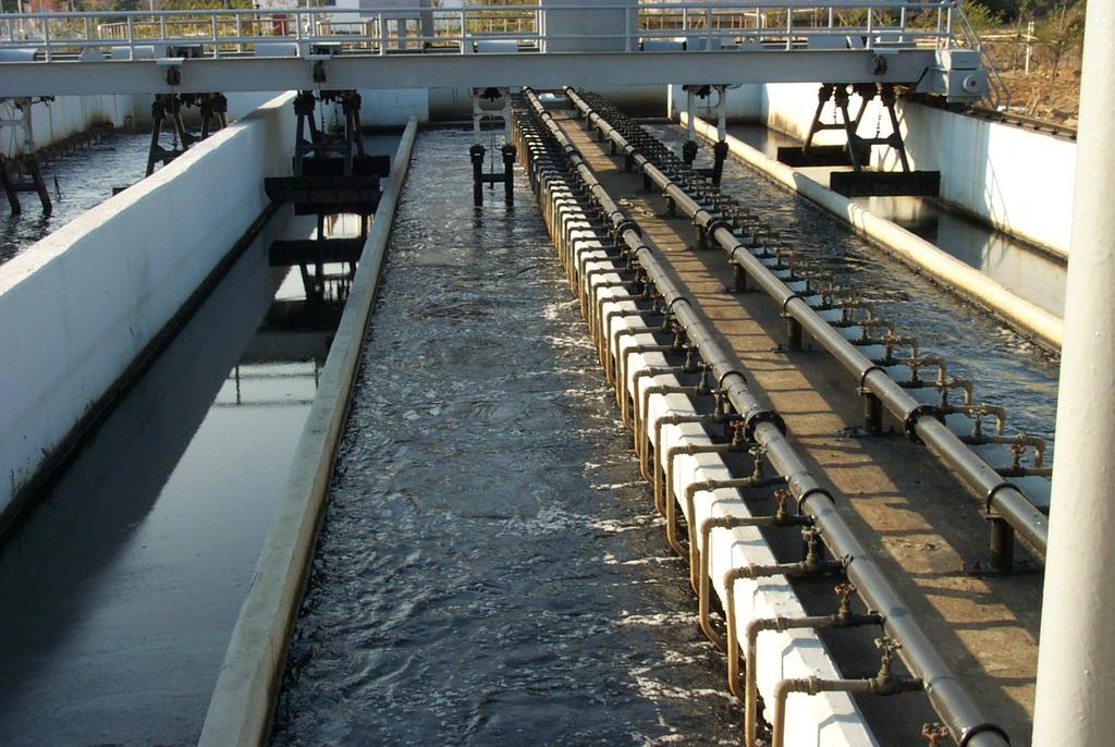
10 2. Grit Removal 10 Grit chambers are designed to removal grit, consisting of sand, gravel, cinders, or other heavy solid materials that have subsiding velocities or specific gravities substantially greater than those of the organic solids in wastewater. Grit chambers are most commonly located after the bar screens and before the primary sedimentation tanks. Primary sedimentation tanks function for the removal of heavy organic solids. In some installations, grit chambers precede the screening facilities. Generally, the installation of screening facilities ahead of the grit chambers makes the operation and maintenance of the grit removal facilities easier.
11 11 Grit chambers are provided to: (1) protect moving mechanical equipment from abrasion and accompanying abnormal wear; (2) reduce formation of heavy deposits in pipelines, and channels, and conduits; and (3) reduce the frequency of digester cleaning caused by excessive accumulations of grit.
12 12 There are two general types of grit chambers: horizontal flow or aerated type. In horizontal flow type, the flow passes through the chamber in a horizontal direction and the straight-line velocity of flow is controlled by the dimensions of the unit, an influent distribution gate, and a weir at the effluent end. The aerated type consists of a spiral flow aeration tank where the spiral velocity is induced and controlled by the tank dimensions and quantity of air supplied to the unit. Design of grit chambers is commonly based on the removal of grit particles having as specific gravity of 2.65 and a wastewater temperature of 15.5 o C. However, analysis of grit-removal data indicates the specific gravity ranges from 1.3 to 2.7.
13 13 Generally, what is removed as grit is predominantly inert and relatively dry material. However, grit composition can be highly variable, with moisture content ranging from 13 to 65 percent, and volatile content from 1 to 56 percent. The specific gravity of clean grit particles reaches 2.7 for inerts but can be as low as 1.3 when substantial organic material is agglomerated with inerts. A bulk density of 1600 kg/m 3 is commonly used for grit. Grit particles 0.2 mm and larger have been cited as the cause of most downstream problems.
14 14
15 15 Horizontal flow Grit Removal: Rectangular or square horizontal flow grit removal have been used for many years. Rectangular horizontal flow grit chambers is the oldest type of grit chamber used. It is velocity-controlled type. these units were designed to maintain a velocity as close to 0.3 m/s as practical and to provide sufficient time for grit particles to settle to the bottom of the channel. The design velocity will carry most organic particles through the chamber and will tend to resuspend any organic particles that settle but will permit the heavier grit to settle out.
16 16 The basis of design of rectangular horizontal flow grit chambers is that, under the most adverse conditions, the lightest particle of grit will reach the bed of the channel that will be retained on a 0.2 mm diameter (65 mesh) screen, although many chambers have been designed to remove grit particles retained on a 0.15 mm diameter (100 mesh) screen. The length of the channel will be governed by the depth required by the settling velocity and the control section, and the cross sectional area will be governed by the rate of flow and by the number of channels. Allowance should be made for inlet and outlet turbulence. Grit removal from horizontal flow chambers is accomplished usually by a conveyor with scrapers. In small plants, grit chambers are sometimes cleaned manually.
17 17 Design criteria of horizontal flow grit chamber according to Egyptian Code: Horizontal velocity = m/s Detention time = s Surface loading rate should not exceed 1200 m 3 /m 2 /d Water Depth = m Width of chamber = (1-2) water depth Vertical velocity = 2 cm/s for particles greater than 0.2 mm Length of chamber = (20-30) water depth Amount of grit settled = l/1000 m 3 /d
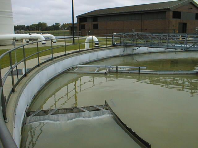
18 3. Primary Sedimentation 18 The objective of treatment by sedimentation is to remove readily settleable solids and floating material and thus reduce the suspended solids content. Primary sedimentation is used as a preliminary step in the further processing of the wastewater. Efficiently designed and operated primary sedimentation tanks should remove from 50 to 70 % of the suspended solids and from 25 to 40 % of the BOD. Almost all treatment plants use mechanically cleaned sedimentation tanks of standardized circular or rectangular design. Two or more tanks should be provided so that the process may remain in operation while one tank is out of service for maintenance and repair work.
19 19 Sedimentation tanks are normally designed on the basis of a surface loading rate ( commonly termed ''overflow rate'') expressed as cubic meters per square meter of surface area per day, m 3 /m 2.d. The selection of a suitable loading rate depends on the type of suspension to be separated. When the area of the tank has been established, the detention period in the tank is governed by water depth. Overflow rates in current use result in nominal detention periods of 2.0 to 2.5 h, based on average design flow. It should be emphasized that overflow rates must be set low enough to ensure satisfactory performance at peak rates of flow.
20 20
21 Design Criteria according to the Egyptian Code: 21 Rectangular tanks Water depth = 3-5 m, Length should not exceed 40 m, Width = 6-12 m Width : length = 1:3-1:5 Bottom slope = 1:40 or 1: 50 Detention time for tanks followed by trickling filter = hrs Detention time for tanks followed by activated sludge = hrs Detention time for tanks without secondary treatment = 3-4 hrs Surface loading for tanks without secondary treatment = m/s Surface loading for tanks followed by biological filters= 1-2 m/s Surface loading for tanks followed by aeration tanks= m/s
22 22 Circular tanks Water depth = m, Diameter should not exceed 40 m Bottom slope = 1:10 or 1: 15 Loading on weir = m3/m/d Detention time for tanks followed by trickling filter = hrs Detention time for tanks followed by activated sludge = hrs Detention time for tanks without secondary treatment = 3-4 hrs Surface loading for tanks without secondary treatment = m/s Surface loading for tanks followed by biological filters= 1-2 m/s Surface loading for tanks followed by aeration tanks= m/s
23 23 Thank you