Enviro Voraxial Technology
|
|
|
- Morris McCormick
- 5 years ago
- Views:
Transcription
1 Enviro Voraxial Technology 821 NW 57 th Place, Fort Lauderdale, FL Phone Fax: EVTN VORAXIAL GRIT SEPARATOR HILLSBOROUGH COUNTY DEMONSTRATION PROJECT REPORT PO NUMBER DPWA SEPTEMBER, 2004
2 Table of Contents EXECUTIVE SUMMARY 1.0 INTRODUCTION 1.1 Project Background Project Objective TEST CONFIGURATION 2.1 Voraxial Grit Separator Test Facility Test Setup TEST RESULTS 3.1 Test Procedures Grit Characteristics Grit Removal Efficiency REFERENCES
3 EXECUTIVE SUMMARY The Hillsborough County Water Department (Department), in its ongoing program to reduce the amount of grit which reaches the Northwest Regional Residuals Recovery Facility (NWRRRF), issued a research purchase order to Enviro Voraxial Technology, Inc. (EVTN) to perform a demonstration program for the removal of grit using a VAS4000GS Voraxial Grit Separator. The patented Voraxial Grit Separator is a technology that separates solids and liquids based on their distinct specific gravities. The impeller in the Voraxial Grit Separator produces a vortex in the fluids flowing through the unit with the heavier materials being drawn to the outside of the vortex, while the lighter materials are drawn to form a central core. A specially designed manifold at the exit of the separation chamber is utilized to collect the separated streams. A test protocol to evaluate the performance of the VAS4000GS Voraxial Grit Separator at the Northwest Regional Water Reclamation Facility (Northwest) was developed with the assistance and support of the Department. The objective for this project is to demonstrate and document the grit removal efficiency of the VAS4000GS Voraxial Grit Separator at the headworks of Northwest. The goal is to evaluate the separation efficiency for the total grit quantity in the wastewater and for a series of grit particle size ranges based a sieve analysis of the collected samples. The VAS4000GS Voraxial Grit Separator was installed at the Northwest headworks during November Since the latter part of February 2004 performance testing has been conducted. From February through July a total of twenty-one (21) performance tests were conducted. Performance tests were conducted with operating conditions simulated for a period of two (2) to over six (6) hours. The test data showed that the grit at Northwest is typical of that found in the southeast with a high amount of sugar sand. Approximately 50 percent of the grit collected at Northwest was less than 150 microns in size and 15 percent was less than 100 microns in size. Testing demonstrated that high efficiency grit removal could be achieved with the reject flow as low as five percent (5%) of the total flow. The percent reject flow is the percent of the total flow which is discharged with the separated grit. This low rejection rate provides for a very stable vortex and produces good performance. The separator was tested a several different speeds; from 1750 rpm to 3150 rpm. The higher the separator speed, the higher the centrifugal force generated and the higher the removal efficiency for grit solids. The highest removal efficiency was obtained at the highest operating speed tested of 3150 rpm (the top operating speed is 3500 rpm). The Overall Efficiency obtained at an operating speed of 3150 rpm varied from 81% to 89%. This means that 81% to 89%, by weight, of the entire range of grit particle sizes in the influent wastewater was removed by the VAS4000GS Voraxial Grit Separator. The entire range of sizes includes those for sugar sand. The performance at 3150 rpm is superior to the present state-of-art for grit removal equipment. The performance of the VAS4000GS Voraxial Grit Separator exceeds that for Vortex-type separators. 3
4 The sieve analyses for the runs at 3150 rpm further demonstrates the highly efficient performance of the Voraxial Grit Separator. Based on the sieve analyses, the following results were obtained: Grit Separation Efficiency of 85% to 95% for 150 to 250 micron particles Grit Separation Efficiency of 87% to 97% for 75 to 150 micron particles Grit Separation Efficiency of 66% to 84% for 45 to 75 micron particles The removal efficiency in the particle size range of 45 to 150 microns exceeded expectations. The data in this particle size range demonstrates excellent performance for removal of sugar sand. In summary, this test program has demonstrated that the VAS4000GS Voraxial Grit Separator is a very efficient grit removal device. The Voraxial Grit Separator achieved excellent Overall Efficiency and the data shows that the separator can remove sugar sand efficiently. 4
5 INTRODUCTION 1.1 Project Background Enviro Voraxial TM Technology, Inc. (EVTN) has developed and patented the Voraxial Separator (VAS). The VAS is a technology that separates large volumes of solids and liquids based on their distinct specific gravities. The low shear, open impeller in the VAS produces a vortex in the fluids flowing through the unit with the heavier materials being drawn to the outside of the vortex, while the lighter materials are drawn to form a central core. In this manner, separated liquids/solids streams are produced. A specially designed manifold at the exit of the separation chamber is utilized to collect the separated streams. For the municipal wastewater treatment industry, EVTN has designed the VAS4000GS and the VAS8000GS Voraxial Grit Separators. The Voraxial Grit Separators utilize a VAS for operation in the headworks of a municipal wastewater treatment plant (WWTP). The Voraxial Grit Separator is designed to provide for the continuous removal of grit from screened wastewater. The VAS4000GS Voraxial Grit Separator is designed for wastewater rates up to one million gallons per day (1 mgd), while the VAS8000GS Voraxial Grit Separator is designed for rates up to ten (10) mgd. The Hillsborough County Water Department (Department) recently initiated several projects which focused on the presence of grit at the Northwest Regional Residuals Recovery Facility (NWRRRF). The NWRRRF serves as the central sludge processing facility for the Department s northwest service area. NWRRRF receives sludge from five wastewater treatment plants in the northwest service area. These treatment plants are the Northwest Regional Water Reclamation Facility (Northwest), the River Oaks Advanced Wastewater Treatment Plant (AWTP), the Dale Mabry AWTP, the Van Dyke WWTP and the Nine Eagles WWTP. The grit received at the NWRRRF causes excessive wear on the plant equipment and requires additional manual cleaning of the four digesters. The digesters are cleaned every two years to remove the grit collected at the bottom of these tanks. Accordingly, the Department, in its ongoing program to reduce the amount of grit reaching the NWRRRF, issued a research purchase order to EVTN to perform a demonstration program for the removal of grit using a Voraxial Grit Separator. This Report presents the results of the demonstration program of the VAS4000GS Voraxial TM Grit Separator installed at the Department s Northwest facility. The test protocol to evaluate the performance of the VAS4000GS Voraxial Grit Separator at Northwest was developed with the assistance and support of the Department. 1.2 Project Objective The objective of this project is to demonstrate and document the grit removal efficiency of the VAS4000GS Voraxial Grit Separator at the headworks of Northwest. The goal is to evaluate the separation efficiency for the total grit quantity in the wastewater and for a series of grit particle size ranges based a sieve analysis of the collected samples. 5

6 2.0 TEST CONFIGURATION 2.1 Voraxial Grit Separator The VAS4000GS Voraxial Grit Separator is designed for installation in the headworks of a WWTP, after the screening unit. An isometric drawing of the Voraxial Grit Separator is shown on Figure 1. Figure 1 Isometric Drawing of Voraxial Grit Separator As shown on the drawing, the Voraxial Grit Separator is configured with an inlet manifold to receive the screened wastewater and two (2) exit manifolds, one (1) for discharge of the removed grit and one (1) for discharge of the screened and degritted wastewater. The screened and degritted wastewater is to be sent for further treatment in the plant, while the separated grit is to be sent to a grit washer and proper disposal. A full-scale, VAS4000GS Voraxial Grit Separator was utilized for the project at Northwest. The four-inch (4 ) diameter Grit Separator is eleven (11) feet long and weighs about twelve hundred (1200) pounds. The separator is driven by a 10 Hp explosion-proof motor. The separator produces a centrifugal force to provide for the separation of grit. The separator produces a force of six hundred seventy nine (679) G s when operating at a speed of 3500 rpm. 2.2 Test Facility The Northwest Regional Water Reclamation Facility (Northwest) is a five (5) mgd activated sludge wastewater treatment facility. The process flow diagram for the Northwest facility is shown on Drawing Number HCDP
7 7
 from Northwest is sent to NWRRRF. A photo of the Northwest headworks is shown on Figure 2.")
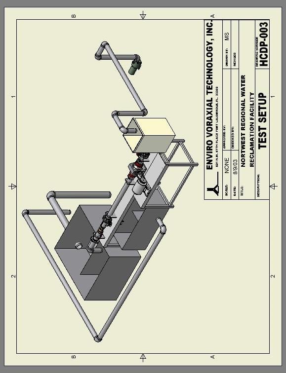
8 As shown on the drawing, wastewater flows received at the headworks include: raw wastewater, sludge sidestream flow from the Northwest Regional Residuals Recovery Facility (NWRRRF), plant drains, and spent filter backwash waters. The drawing also shows that waste activated sludge (WAS) from Northwest is sent to NWRRRF. A photo of the Northwest headworks is shown on Figure 2. The headworks at Northwest consist of a mechanical bar screen and degritting equipment. A Smith & Loveless Pista Grit Removal System is used for grit removal. The wastewater feed to the VAS4000GS Voraxial Grit Separator is obtained from the headworks influent channel downstream of the mechanical screen and upstream of the grit collector. Figure 2 - Northwest Regional Water Reclamation Facility Headworks 2.3 Test Setup An isometric drawing of the Demonstration Project test setup is shown on Drawing Number HCDP-003. A Flow Diagram of the test setup is shown on Drawing Number HCDP-001. As shown on the flow diagram, the Voraxial Grit Separator was installed to operate in parallel with the influent channel at Northwest. It was installed to treat a sidestream from the headworks channel. Photos of the test setup are shown on Figures 3 through 5. A submersible non-clog Flygt Solids Handling Pump (PP1) was used to transfer the wastewater from the headworks influent channel to an Equalization Tank (T1) upstream of the VAS4000GS Voraxial Grit Separator. This is shown on Figure 3. The Equalization Tank simulates the headworks influent channel with respect to operation of the Voraxial Grit Separator. 8
9 9
10 10


11 Figure 3 - View of Inlet Pipe and Equalization Tank Feed to Voraxial Separator Figure 4 - View of Voraxial Grit Separator, Grit Collector Tank and Main Tank 11
 was utilized to record the flow rate in the feed line.")
12 Figure 5 - Discharge Pipes for Return Flow to Northwest Influent Channel The test configuration has Control Valve (V1) in the feed line to balance the flow into and out of the Equalization Tank. A portable doppler ultrasonic Flow Meter (FM) was utilized to record the flow rate in the feed line. Grit separated from the wastewater is discharged from the Heavy Manifold Valve (V3) to the Grit Collector Tank (T2). Degritted wastewater is discharged from the Light Manifold Valve (V4) to the Main Flow Tank (T3). Tanks 2 and 3 are shown on Figure 4. These tanks utilize a weir to measure the flow rate to each tank and to provide for return of the wastewater to the headworks influent channel. Baffles are installed in each tank to direct the discharge in a downward direction and prevent short-circuiting. The discharge pipes for return of the wastewater to the influent channel are shown on Figure 5. 12
13 3.0 TEST RESULTS 3.1 Test Procedures There are no standard test procedures for evaluating the performance of grit removal equipment. Accordingly, the procedures employed for the Hillsborough County Demonstration Project were adapted to accomplish project objectives, while utilizing the space and equipment available at the operating Northwest facility. Performance tests were conducted with operating conditions (principally, Voraxial Separator speed, and percent reject flow to the Grit Collector Tank) simulated for a period of two or more hours. The maximum test run duration was over six (6) hours. At the end of a test run, floatables were skimmed off the top of Tank T2 and Tank T3, and the supernatant was pumped from each tank until approximately one-inch (1 ) of liquid/grit slurry remained on the bottom. The liquid/grit slurry on the bottom of the tanks was passed through a 200 mesh screen to drain water from the sample. The wet weight of each grit sample was determined in the field. At the completion of each performance test the separator was inspected to check the impeller and separation chamber for any accumulation of grit solids. The wet grit samples were sent to the Hillsborough County Water Department Environmental Laboratory (Environmental Laboratory) for determination of the percent total solids and the percent volatile solids. The percent total solids and percent volatile solids were determined in accordance with Part 2540G in Standard Methods. With the percent total solids and percent volatile solids determined, the total quantity of fixed grit solids collected in Tank T-2 and in Tank T-3 was found. By performing a mass balance the total quantity of fixed grit solids passing through the separator was also determined. With the flow rates and grit quantities determined, the separation efficiency for the simulated condition was calculated. The efficiency determined for the total quantity of grit is referred to as the Overall Efficiency. It is a measure of the percent of the total quantity of grit in the influent wastewater which is removed by the Voraxial Grit Separator. It is believed that this arrangement is unique and results in a good measurement of separated grit. Following determination of the percent total solids and percent volatile solids in the Environmental Laboratory, the samples were sent to a contract laboratory for a particle size distribution analysis. The general procedure used to perform this analysis was ASTM D422-63, Standard Test Method for Particle-Size Analysis of Soils. For this procedure, samples are dried in an oven at 110 o C prior to performing the analysis for particle size distribution. However, when the sample contained a consequential amount of organic material with the sand, the dried samples were placed in a muffle furnace at 650 o C to burn off the organic material prior to performing the particle size distribution analysis. The size distribution of particles larger than 75 microns was found by sieving, while the distribution for smaller particles was determined by a sedimentation process using a 13
14 hydrometer. Contract laboratories utilized for this analysis were ELAB, Inc. from Ormond Beach, Florida and Driggers Engineering Services, Inc. of Tampa, Florida. ELAB, in turn, subcontracted with Thompson Engineering in Mobile, Alabama for the particle size distribution analysis. Using the percent finer data, the weight of grit removed over various particle size ranges was found. Based on this data, the removal efficiency for specific grit size ranges was determined. 3.2 Grit Characteristics The grit collected at Northwest is typical in appearance and in measured physical properties to that reported in the industry. Grit consists mainly of sand and gravel or other materials with specific gravities greater than those of organic solids. In addition, grit also often includes seeds, coffee grounds, and large organic particles such as food wastes. The physical description of the grit samples collected at Northwest ranged from various shades of gray or black fine sands to sand trapped in an organic fibrous matrix. Grit composition can be highly variable, with the moisture content reported to range from 13 to 65 percent, and volatile content from one (1) to 56 percent (1). The grit collected at Northwest had a moisture content range of 30 to 88 percent and a volatile content of zero (0) (no organic content reported) to 52 percent. The average volatile content was approximately 20 percent. The size distribution of grit varies due to differences in service area location and characteristics, and collection system characteristics. Generally, most grit particles are retained on a No. 100 mesh (150 microns) sieve. However, in the southeast, such as in Hillsborough County, the grit can be much finer. In the southeast, fine sand known as sugar sand constitutes a much greater portion of the grit. It has been reported that less than 60 percent of one southeast city s grit was retained on a No. 100 mesh screen (2). At Northwest, the amount of grit less than 150 microns was approximately 50 percent. Fifteen (15) percent was less than 100 microns. A composite sieve analysis for the test runs is shown on Figure 6. Removal of grit particles smaller than 150 microns is important at Northwest (and at other plants in the Department s northwest service area) based on a study by Camp Dresser & McKee (3). The study indicates that the grit loading at the NWRRRF may be reduced by at least 50 percent by the removal of grit particles down to 100 microns size. The amount of grit in sewage varies greatly from one location to another, depending on the characteristics of the drainage area, the conditions of the sewers, and the types of wastes treated. Grit is normally present in raw sewage at a level of about 5 or 6 parts per million (ppm) (4). This is approximately 40 or 50 pounds of dry grit per million gallons (lb/mgal) of raw sewage. The quantity of grit collected at Northwest during the test was from screened sewage and had a maximum value of 67 lb/mgal. 14
15 Figure 6 Hillsborough County Demonstration Project Composite Sieve Analysis Percent Finer by Weight - % Grit Size - microns 3.3 Grit Removal Efficiency The VAS4000GS Voraxial Grit Separator was installed at the Northwest headworks during November Initial operations at Northwest were conducted to prepare the test configuration, to install and check out auxiliary test equipment, and to develop data collection procedures. Since the latter part of February 2004 performance testing has been conducted. Performance testing was conducted periodically through the end of July From February through July a total of twenty-one (21) performance tests were conducted. Performance tests were conducted with operating conditions simulated for a period of two or more hours. The principle operating conditions simulated during each run were separator speed (rpm) and reject flow (as a percent of total flow). The tests conducted are summarized on Table 1. The run numbers on Table 1 are in the order of the test sequence, except that when a combination of the separator speed and the reject flow was repeated, a second sequence number was used after a dash (i.e., the 2- and the 7- series). Testing demonstrated that high efficiency grit removal performance could be achieved with the reject flow as low as five percent (5%) of the total flow. This low rejection rate provides for a very stable vortex and produces superior performance. As a result, the five percent (5%) rejection rate was used for the bulk of the tests. 15
16 Run Number Table 1 Run Summary Hillsborough County Demonstration Project Run Date Separator Speed (Rpm) Nominal Reject Flow (%) Run Length (hr) Separator Flow (gpm) 1 2/19/ /25/ /2/ /3/ /17/ /30/ /8/ /26/ /27/ /17/ /18/ /8/ /9/ /13/ /14/ /15/ /21/ /22/ /23/ /29/ /30/ A summary of the Overall Separation Efficiency for a nominal five percent (5%) reject flow is shown on Table 2. Runs 4, 5 and 6 are not included on Table 2 because the reject flow was set at ten percent (10%). The reject flow shown on the table is based on the measured flow over the weir. Floatable materials were not removed from the tanks for Run 2-3 and Run 2-6 and these materials were collected in the samples. As a result, these runs were not included on Table 2. Wet sample data was not available for Run 2-4 and the efficiency for this run was based on the dry inert weights reported by the contract laboratory. The test durations varied from two (2) hours to six and a quarter (6.25) hours. Although there was a slight trend of a higher efficiency with a longer run time (for the same speed and reject flow), the run time was mostly dictated by weather conditions, operation of auxiliary equipment, and the time of day. 16
17 Run Number. Separator Speed (Rpm) Table 2 Voraxial TM Grit Separator Overall Separation Efficiency Run Length (hr) Reject Flow (% of Total Flow) Separation Efficiency (%) The separator speed was varied from 1750 rpm to 3150 rpm with the majority of runs at 2800 rpm to establish a broad data set at a nominal speed. The higher the separator speed, the higher the centrifugal force generated and the higher the removal efficiency for grit solids. Accordingly, the highest removal efficiency to date was obtained at the highest operating speed tested of 3150 rpm (90% of full speed). This is illustrated on Figure 7, which is a plot of the Overall Efficiency versus the Voraxial Grit Separator speed. The Overall Efficiency obtained for Run 7 was 89%. This means that 89%, by weight, of the entire range of grit particle sizes in the influent wastewater was removed by the VAS4000GS Voraxial Grit Separator. The entire range of particle sizes includes those for sugar sand. The Overall Efficiency obtained for Run 7-2 was 81%. The performance at a speed of 3150 rpm is superior to the present state-of-art for grit removal equipment. Even at a lower operating speed of 2800 rpm the Voraxial Separator demonstrated high efficiency grit removal performance, reaching a high of 90% Overall Efficiency for Run
18 Figure 7 Hillsborough County Demonstration Project Grit Removal Efficiency 5% Reject Flow Grit Removal Efficiency - % Voraxial Grit Separator Speed - rpm The sieve analysis for the runs at 3150 rpm, further demonstrates the efficient performance of the Voraxial Grit Separator. Table 3 shows the removal efficiency obtained during these runs for specific particle size ranges, as well as typical design data reported for Vortex-type Grit Separators (5). Mesh Table 3 VAS4000GS Grit Removal Efficiency vs. Vortex-type Grit Separators Particle Size Range (microns) VAS4000GS Efficiency for Particle Size Range * Vortex-type Grit Separator Design Efficiency (5) % % - 95% % % - 97% % - 84% * VAS4000GS Efficiencies are for operation at 3150 rpm. As shown on Table 3, the performance of the VAS4000GS Voraxial Grit Separator compares quite favorably with that for Vortex-type separators. In particular, the removal 18
19 efficiency in the particle size range of 45 to 150 microns is very substantial. The data in this particle size range demonstrates excellent performance for removal of sugar sand. In summary, this program has demonstrated that the VAS4000GS Grit Separator is a very efficient grit removal device. The VAS4000GS Grit Separator achieved excellent Overall Efficiency and the data shows that the separator can remove sugar sand efficiently 4.0 REFERENCES 1. Metcalf & Eddy, Inc. Wastewater Engineering; Treatment. Disposal, Reuse, 3rd Ed. McGraw Hill, New York, 1991, p Ibid. 3. Grit Source Study for Northwest Regional Residual Recovery Facility, Camp Dresser & McKee, October 2001, pes Pista Grit Chamber Field Test, Smith & Loveless, Inc., Factsheet. 5. Metcalf & Eddy, Inc. Wastewater Engineering; Treatment. Disposal, Reuse, 3rd Ed. McGraw Hill, New York, 1991, p