BioBowser. 'Powering the Future'
|
|
|
- Pierce Grant
- 5 years ago
- Views:
Transcription

1 BioBowser 'Powering the Future' Biogas technology that provides innovative, affordable and practical solutions to generate returns from organic waste streams. Biog Ltd Ålesund/Norway

2 BioBowser is our range of modular, packaged biogas plants. It is an exciting Australian innovation designed to handle smaller quantities of waste. BioBowser is a new concept designed to be installed quickly and integrate with existing waste handling procedures at minimal cost with minimal disruption. 2
3 BioBowser Specifications * Is a useful waste management tool for cleaning up effluent ponds and handling food waste from processing facilities or large kitchens/canteens * Improves on-site waste, odour and carbon emission management and water quality * Is a new concept designed to be installed quickly and integrate with existing waste handling procedures at minimal cost with minimal disruption. * Is a practical, affordable stepping stone for bigger farms and processing facilities as they explore the feasibility of a large purpose built biogas plant. * Reuses the biogas it produces to power itself via a biogas generator and/or hot water heating * Produces fertilizer which can be stored and used on farm or on-sold. Manure separator also not a part of standard package but is under development. Currently designs can be provided for manure settling ponds/tanks to be built in brick and cement on site of installation. * Base module treats 1 tonne per day of organic waste and fits within the footprint * Shipping occurs protected on a framed skid including all of the components and also metal sheeting to be applied to the outside on installation (reduced production and transport costs and improved aesthetics) * Is modular and scalable to 2 tonnes of feedstock per day based on the type of feedstock. * Commercially available from January 2010 Capacity 500 Kg s of segregated wet organic waste processed per day. (Food waste 18% TS) litres tank volume. Waste handling capacity from 100 Kg s 550 Kg s per day. Inputs (per day) 500 Kg s segregated 500 Litres water. 2 Hours of operational time. Outputs (per day) 30 m Kcal/m3. (applicable with food waste medium grease content with 18% TS) This is equivalent to: 15 Kg s L.P.G. or 45 kw per Day Power generation capacity with the help of a biogas powered generator*. 900 litres Organic Liquid Manure with 4-5% Solids. This is equivalent to: Kg s of organic manure or 3-4 Kg s of chemical fertilizer. *Biogas fired Burners and Electricity Generator additional to standard Bio Bowser package. 3
4 1. The biogas plant system rests on a framed skid (the complete biogas system including the feeding system, treatment system, gas generation and utilization system, gas cleaning system and the process control system) was designed by us for operating and installing biogas plants professionally in a very well aesthetic way. 2. The plant on a framed skid is equipped and designed in such a way that it houses the entire high quality treatment system. 3. The compact design of the entire biogas unit is built to industrial standards and it ensures trouble free and regular operation system with a outstanding efficiency for regular operations. The generation and the use of the biogas are optimally tailored to one another. 4. The biogas system has already been tested for safety and is ready to use plant and can be installed and started immediately anywhere wherever it is delivered. 5. The only requirements would be the gas, manure, electricity and the solar system needs to be connected to the kick start the system. 6. Consequently the anaerobic digester can easily be commissioned and stabilized by the easy system which we mention in our manuals. 7. The entire system is designed in a complete package which converts any kind of biodegradable waste into biogas as well as manure/liquid fertilizer with the help of specially designed very high performance digesters which are the heart of the entire system. 8. Each and every item used in the entire system is highly tested with its certificates and the motors, gearboxes etc have been tried and tested over many years to ensure the optimum efficiency without any shut down of the system. 9. We normally provide a repair tool kit as well as a operating manual which guides the operator to easily understand and handle any kind of waste without any operating problems and how to overcome the minor problems which are generally faced by the operators at plant. 10. The biogas plant is equipped with a standard control system which is semi automated and the entire process can be easily managed. This control panel features an operating and observation system which enables the operator at the plant site to monitor as well as to operate the biogas plant at the same time with no wastage of time. This panel not only allows the entire electrical components to be controlled but also indicates the operator in case of any upcoming emergency. 11. We do design the entire system in such a way that we ensure minimum handling of waste and minimum working time at the site 12. The Blending and the feed inlet system which is equipped with a controlled pumping system, using a number of suction and a pressure lines. As a result the substrate which is to be fed to the digester passes flexibly and in a fully controlled system between the blending and the digesting system. 13. The Thermostat is fixed on the manhole from where easily the internal digester temperature can be checked and alternatively it can be maintained which ensures a reliable operation. 14. The biogas plant is a very low maintenance system designed especially and was extremely important for various farms where it can be used with low maintenance, therefore a number of special features have been built and also some of the critical factors compared to other biogas systems have been minimized to reduce the maintenance time. 15. This concept of a biogas plant inside a container is just ready to use Biogas System which has already been tested and can be used when it is delivered. As a result; The overall construction time is reduced and saved. The on-site installation time is extremely short. There are no interface problems on the construction site. The entire system can handle and treat any kind of biodegradable waste, were we generally give the perfect tailored made overall system. Efficient work which inside a compact system with good aesthetic looks. The system is designed in such a way that it is User friendly, service friendly, less maintenance and hence maintenance friendly system. 4


 Models:")
 Fully steel, portable and ready to use.")


5 Power Consumption Installed Power** load Consumption Crusher: 3.5 kw x 2 Hours = 7.0 kwh Agitator: 1.5 kw x 4 Hours = 6.0 kwh Feed Pump: 0.75kW x 2 Hours = 1.5 kwh Heat Pump: 0.25kW x 5 Hours = 1.2 kwh TOTAL CONNECTED LOAD = 10 HP TOTAL CONSUMPTION PER DAY = 15.7 kwh POWER* COST PER DAY = $2.94 * Power 18.7c per kwh and 3 Phase Connection Standard digester size for feed in volumes (combined waste and waste water at max 25% TS) Models: BioBowser 500 (500kg) BioBowser 1000 (1000kg) BioBowser 1500 (1500kg) BioBowser 2000 (2000kg) Fully steel, portable and ready to use. FCSTR (continuously stirred9 model with biogas fired heater to maintain the ambient temperatures. CSTR model available with solar heating to maintain the ambient temperatures. State-of-the-art control panel. Universal Waste feed in Volume/Day Capacity BioBowser. A packaged Biogas Generation Plant. Slick and elegant design. Enclosed design, minimal preparation and installation requirements, designed to be transported and handled. BioBowser plants are fully integrated plant with H2S and CO2 cleaning systems and piping and fittings. 5


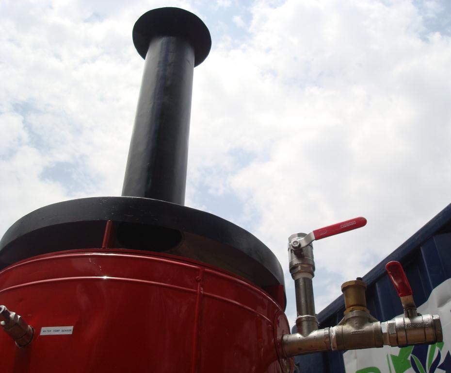


6 AUTO CONTROL PANEL UNIT AUTO CONTROL PANEL UNIT GAS CONNECTIONS TO BALOON BOWSER FRONT END HEAT EXCHANGER EXHAUST DROP CHUTE BIOGAS BURNER 6
7 7
8 BIO BOWSER 2000 PROCESS DESCRIPTION 1. FEEDING SYSTEM: 1.1. FOOD WASTE CRUSHER: The crushing capacity of the food waste crusher is approx 200 Kg 500 Kg/hour with maximum inlet capacity of the particles allowed is 150mm and the particles released from the crusher after crushing alongwith the water is not more than 4mm, the maximum solids allowed while crushing is about 12%. The crusher has a motor of 5HP rating with 2900 RPM. Waste is fed to the crusher along with the water in the ratio 1:1 and is homogenised and fed to the feeding buffer tank FEED BUFFER TANK: The feeding buffer tank acts as a buffer tank between the digester and the food waste crusher and it is of 500 litres capacity with 40 mm outlet connected to the feeding screw pump. The homogenised waste and water in the form of slurry is delivered in this digester by the food waste crusher and is pumped inside the digester with the help of the feeding screw pump SCREW PUMP: (Screw type positive displacement pump/screw Pump): The screw feeder blends the waste and the water (slurry) deposited by the food waste crusher inside the feed buffer tank and delivers the slurry to the digester FEED PIPE & DROP CHUTE: Liquid Slurry from the feed buffer tank is delivered by the screw feeder thru the feed pipe which acts as a connection between the drop chute and the screw feeder and any foreign particle of sizes above the desired level if fed to the feed pipe it directly gets collected at the bottom of the drop chute and can be removed periodically by opening the butterfly valves. There is a sudden drop in the pipe size of the feed pipe and the pipeline size of the drop chute only because to collect any unwanted heavy foreign particle at the bottom of the drop chute. 2. DIGESTER: 2.1. TANK DIGESTER: The Digester accepts the effluent slurry from the screw feeder via feeding pipe and the drop chute. The effluent is transformed overtime by the bacterial populations within the reactor into Bio-gas and Bio-sludge. The bacterial populations require particular temperature and ph conditions in order to thrive and effectively treat the incoming effluent. The entire internal temperature is monitored continuously and is maintained at 40 C and is the primary basis for control of the entire digester. Any change inside the digester is continuously maintained with the help of heat exchangers inside the digester. Biogas is drawn off the top of the digester and is delivered to the biogas storage bag/balloon and from there further it is delivered to the desulphurization via the first water/moisture separator and is further delivered to the carbon scrubber and is then fired with the help of a biogas burner connected to the blower for maintaining the pressure. Bio-sludge/organic fertilizer is drawn off from the top via gas fluid separation chamber and is allowed for natural settlement inside another additional tank. The entire digester is insulated which ensures there are minimum temperature losses and if there are any losses is maintained by the heat exchanger. The complete internal system/slurry is stirred in a interval of 30 minutes with the help of submersible agitator and is allowed to run for five minutes in every 30 minutes. This agitation helps to get better gas yields and also ensures there is no formation of scum or no deposits of the solid particles inside the digester. **NOTE: Tank insulation is not required if the Bio Bowser is installed in warm climate countries. 8
9 3. HEATING SYSTEM: 3.1. RECIRCULATION WATER PUMP: The water from the heat exchangers is pumped out with the help of the recirculation water pump and is connected between the digester and the solar panels. This 0.5 HP mono-bloc pump works continuously for 24 hours HEAT EXCHANGER TANK WITH CONTROLLING THERMOSTATS: The hot water tank acts as a buffer tank between the solar panels and the digester and any loss of water is maintained by adding water to this tank. This 300 litres tank is insulated with 50 mm polystyrene so there are no losses in temperature. Thermostat controlled extra electric immersion heater of 15 kwhrs is placed inside the tank to recover the losses in temperature. The temperature of water to be circulated maintained at 60 C and if there is any loss in this temperature due to non availability external heat the immersion heater will start and the temperature will be maintained at the desired level PRESSURE RELEASE VALVES: There are 2 pressure release valves are placed in the hot water recirculation line as well as the Hot water buffer tank to release the extra steam pressure if any on an emergency situation. 4. GAS COLLECTION AND CLEANING SYSTEM: 4.1. GAS STORAGE BAG/BALOON: Biogas generated from the digester after 25 days retention time is collected every day in the gas storage balloon. The balloon is roof mounted and is hanged with the help of G cramps and is fitted with the 3 inlet/outlet fittings at the top of the balloon and one outlet at the bottom to drain off the excess moisture collected inside the balloon. The balloon has the capacity of 2.5Ǿ x 10mtr (L) = 50 m³ storage space under inflated state H2S SCRUBBER: The Desulphurization Unit chemically traps the hydrogen sulphide component of the bio-gas by reacting it with iron in the form of steel wool/iron sponge. The desulphurized bio-gas is passed via the first Water/moisture Separator/trap. The Desulphurization unit is designed in such a way that 3-5 kg of loose iron sponge can be replaced periodically whenever replacement of the iron sponge is required. The ratio of 1 Kg iron sponge: 6 Kg of Hydrogen sulphide after scrubbing CO2 SCRUBBER: Biogas after scrubbing hydrogen sulphide passes thru the Carbon Dioxide scrubber which scrubs the carbon dioxide from the biogas. Potassium hydroxide in addition to water and the utilized capacity will be around 15 litres where Potassium hydroxide reacts with carbon dioxide to give bicarbonate. The biogas from the desulphurisation unit is fed to the carbon dioxide scrubber from the bottom and the gas enters the unit after passing thru the diffuser disc made up of 416 holes of 2mm each. The entire unit is transparent and is made up of acrylic so that it is easy to detect when to change the potassium hydroxide solution after the change in the color. The gas after scrubbing passes out and thru the second water/moisture separator/trap GAS PRESSURISING SYSTEM: This system comes with a vacuum pump of 1 HP power to deliver the pressure of 2000 MMWC and a flow rate of20 m3/hr. This is further connected to a gas buffer flow control tank of 300 mm Ø and 600 mm Height with 28 lit capacity.this will control the flow rate of the gas to suit the gas burner (heat exchanger) needs. 5. SUPERNATENT/DIGESTATE DISCHARGE SYSTEM: 5.1. GAS FLUID SEPARATION CHAMBER: The daily digestate is discharged from the top of the digester via gas fluid separation chamber where the biogas is discharged from the top of the gas fluid separation chamber and the solids flow out thru this chamber. This chamber separates biogas throughout 24 hours and the digestate is separated at the time of feeding. Fitted with a hose pipe enough of the length to deliver the slurry outside the Bowser container, it completes the system. Biog Ltd Breivika Industrivei Ålesund/Norway post@biog.as 9