Multi-Component Remediation of Petroleum and Metals at a Former Power Plant in San Francisco, California
|
|
|
- Jean Gaines
- 5 years ago
- Views:
Transcription


1 Multi-Component Remediation of Petroleum and Metals at a Former Power Plant in San Francisco, California October 2 nd, 2014 Insert then choose Picture select your picture. Right click your picture and Send to back.


2 Site Setting Site is located in San Francisco, California and is adjacent to the San Francisco Bay Site encompasses ~4,000 m 2 of shoreline and industrial land Significant portions of the site consist of bay fill placed over bedrock, shoreline deposits, and Bay deposits SF Bay SF SF Bay 2 Google Earth Pro
3 History : Former Power Plant provided electricity for 75 years to San Francisco homes and businesses now decommissioned : Demolition of the plant and related facilities completed : Remedial Investigation (RI), Human Health Risk Assessment (HHRA), and Remedial Action Plan (RAP) completed 2007: Slurry wall and groundwater extraction system installed to prevent plume migration to San Francisco Bay (still operating) (ongoing): Soil and groundwater remediation 2010 to 2012 Soil and onsite groundwater remediation across the site 2013 to 2014 (active) Groundwater remediation of off-site area and small onsite area 3


4 History Decommissioning Former Power Plant Property Now 4
5 Chemicals of Concern Total Petroleum Hydrocarbons (TPH) as Bunker, Jet Fuel, Diesel Fuel, and Motor Oil Light Non-Aqueous Phase Liquid (LNAPL) Volatile Organic Compounds (VOC) Polyaromatic Hydrocarbons (PAH) Polychlorinated Biphenyls (PCB) Dioxins Metals 5

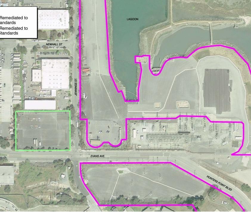
6 Geology and Groundwater Flow Pre-Remediation TPH/LNAPL Plume Off-Site Plume Area GW Barrier: Installed after Excavation completion 6
 Groundwater is 3 meters below ground surface and flows east toward SF Bay Groundwater levels have fluctuated over time to create a smear zone of petroleum 1.")
7 Geology and Groundwater Flow Excavated/Backfilled Areas Fill/Native Soil Smear zone Bay Mud Bedrock Heterogeneous fill material, native soil, Bay Mud, and Serpentine bedrock Fill material and bedrock contain naturally occurring asbestos (NOA) Groundwater is 3 meters below ground surface and flows east toward SF Bay Groundwater levels have fluctuated over time to create a smear zone of petroleum 1.0 meter thick near water table 7
8 Project Objectives Protect community human health for residential, commercial, and public access (parks) land use Prevent migration to ecological receptors in the San Francisco Bay Meet regulatory cleanup goals based on the HHRA, RAP, and ecological studies: Soil residential land use Soil vapor residential land use Groundwater residential land use and prevent migration to Bay Engage the local community during the cleanup process Prepare the property for redevelopment to enhance the community 8
9 Cleanup Goals On-site Soil and Soil Vapor The HHRA developed conservative soil cleanup goals based on conservative screening levels for residential land use Aroclor-1248, Arsenic and Lead cleanup goals were modified downward from screening levels Soil vapor cleanup goals were established to prevent intrusion into potential future buildings 9
10 Cleanup Goals Site-Wide Groundwater 1. To prevent indoor air intrusion - Based on the HHRA 2. To prevent migration of COCs to SF Bay in excess of goals to protect ecological receptors - Modeling USEPA BIOSCREEN Setup/calibrate with Site and Published Hydraulic and Attenuation Parameters Assumptions for Target Modeling Product removed BCS and LCS removed ISCO completed Residual TPH remains No source decay Model separate/combined impacts of 3 areas Site Jennings B-South Models predicts groundwater TPH Targets that will result in no RWQCB Saltwater Environmental Screening Levels (ESL) exceedances at shoreline Model BCS and LCS Removed Point of Compliance for ESLs: TPH-G 3,700 ug/l TPH-D+MO 640 ug/l

11 Cleanup Goals Site-Wide Groundwater Zone TPH Target (µg/l) TPH in this slide = TPH-d + TPH-mo Zone 4 Zone 3 Zone Zone Zone 6 Zone TPH ESL 640 µm/l
12 Multi-Component Remediation Overview Soil Excavation and off-site disposal Groundwater On Site Areas with LNAPL that were excavated near the water table to address vadose zone impacts were over-excavated and subjected to extraction and chemical oxidation in the open excavations A cement-bentonite slurry cutoff wall and sheet-pile cutoff wall, along with low-flow groundwater extraction, are being used to prevent migration of LNAPL and TPH to Bay and previously remediated areas Off-Site 12 Areas with LNAPL where excavation could not be performed were subjected to LNAPL recovery with surfactant-enhanced vacuum extraction Areas with dissolved phase COCs above cleanup goals were treated with and in situ chemical oxidation (ISCO) to oxidize dissolved TPH/VOCs and enhance aerobic biodegradation
13 Onsite Soil Remediation Approach Excavation extended to Groundwater Excavation and off-site disposal Extensive dewatering to access smear zone Targeted shoring Dust, NOA* and odor control *NOA Naturally occurring asbestos Soil remediation excavation 13


14 Naturally Occurring Asbestos Practices Goal: To prevent NOA inhalation by workers and community Dust/NOA mitigation included the use of: mobile misting station handheld mist guns perimeter mist system high pressure/low volume atomized spray Daily monitoring and reporting Applied Odex for odor control 14


15 Onsite Soil Remediation Results Targeted shoring Excavation depth up to 4.8 meters Excavation and disposal of 125,317 metric tons of soil to meet Remedial Action Goals Excavation activities were performed during ~2.5 months Dust/NOA suppression system successful in protecting workers and the community Soil transport to landfill by rail instead of trucks for lower greenhouse gas emissions eliminated the emission of approximately 4,500 metric tons of CO 2 15


16 Onsite Groundwater Remediation Approach Application of RegenOx and ORC in base of excavation into water table Mobilized LNAPL for recovery Oxidation of TPH Enhanced aerobic degradation 16 Oxidizer application in base of excavation into water table

17 Onsite Groundwater Remediation Results Decrease from µg/l to ND levels Decrease from µg/l to ND levels Cleanup goals were met LNAPL removed from onsite areas Completed remediation of onsite dissolved phase plume 17 Vapor intrusion from GW


18 Mid-Plume Barrier Control System Groundwater extraction well Sheet pile groundwater barrier 18 Goal to prevent migration from off-site plume to remediated area and Bay Impermeable sheet pile barrier Groundwater and vapor extraction and treatment upgradient of barrier LNAPL separation and disposal
")


19 Offsite LNAPL Recovery Approach Two-phase approach: Recovery of product in excess 42 extraction events (11 months) Recovery of resilient product in selected wells 3 events thus far Phase 1. Vacuum Truck Extraction Phase 2. Surfactant Enhanced LNAPL Recovery Product thickness reduced from 0.76 m to 0.02 m LNAPL + Groundwater alone LNAPL + Groundwater with surfactant 19

20 Offsite LNAPL Recovery Approach Surfactant Selected: Surbec Surbec produces an ultra-low NAPL/groundwater interfacial tension Surbec can reduce interfacial tension by 3 to 4 orders of magnitude, ideal for LNAPL mobilization in a porous media Phase 2. Surfactant Enhanced LNAPL Recovery Utilize surfactant to flush unsaturated zone and water table interval Injected 3,000-4,500 liters of surfactant each into 13 wells Surfactant = Water + 1% Surbec by weight Extracted 110% of the total volume injected into each area 20


21 Offsite LNAPL Recovery Results Recovered LNAPL Improved LNAPL Recovery with Surfactant Surfactant 13.6L (3.6 gallons) of LNAPL per 3,785L (1,000 gallons) total recovered 21 No Surfactant 3L (0.81 gallons) of LNAPL per 3,785 L (1,000 gallons) total recovered
22 Offsite Groundwater Remediation Approach 3 Phases of in situ chemical oxidation completed Phase I - RegenOx solid oxidant + iron catalyst Phase II and III - modified Fenton s reagent Stabilized 12% liquid hydrogen peroxide and chelated iron catalyst Typical injection volume between 3,000 and 4,500 liters per well in up to 51 wells Radius of influence between 3 and 4.57 meters Exothermic reaction: 5 pinched wells 22

23 Offsite Groundwater Remediation Results TPH Concentration Decreases Due to In Situ Chemical Oxidation Generally, a spike in concentration was observed after Phase I due to mobilization of adsorbed LNAPL into dissolved phase. Followed by decrease in concentrations due to ISCO. 23

24 Offsite Groundwater Remediation Results Pre-Remediation TPH/LNAPL Plume Off-Site Plume Area after completion of excavation Current impacts
25 Conclusion - Results and Lessons Learned Soil Excavation of approximately 125,317 metric tons - achieved remedial action goals for soil and soil vapor Best practices and specialized water application technologies implemented to control the NOA and fugitive dust and protect workers and public Transport to landfill by train more sustainable than truck Groundwater On-Site groundwater concentrations decreased from >100,000 ppb to low to nondetect for fuel-related COCs Off-Site groundwater concentrations significantly decreased as a result of 3 rounds of ISCO. Off-site plume area has decreased significantly and currently only few small areas remain LNAPL Recovery Surfactant-enhanced vacuum extraction increased recovery of LNAPL between 3 and 4 times Mid-Plume Barrier Control Wall and Cutoff Wall successful in preventing migration and recontamination of Area B-South and the neighboring Bay 25
26 End of Presentation Questions? 26