LOCKFORMER ELECTRIC RESISTIVE HEATING CASE STUDY
|
|
|
- Linette Martin
- 5 years ago
- Views:
Transcription


1 LOCKFORMER ELECRIC RESISIVE HEAING CASE SUDY U.S. EPA Emergency Response Branch Steve Faryan, On-Scene Coordinator ,

2

3
4 Lockformer ERH Case Study he Removal Action is being conducted under a Unilateral Administrative Order issued by U.S. EPA ERH was selected as treatment technology for the 32,000 cubic yards of upper clay till/fill which is contaminated with CE Soil Vapor Extraction was selected for the underlying sand and gravel
5 Lockformer Case Study Site contaminants include CE and breakdown products Historical Spills of CE with high levels of soil contamination (range 1 ppm 2,000 ppm of CE) Ground water and lower till is being addressed under Illinois EPA order (concentrations were below Removal Action Levels)
6 Electric Resistive Heating Same a Six Phase Heating Developed by Batelle but several contractors provide the technology Utilizes electric current to heat the soil to C Vapor extraction is provided at the electrodes and at the surface under the plenum
7
8 Lockformer ERH Area M N C D E 1 O 2 F K P 3 4 Q R AREA H AREA B C D E F G H ELECRODES (117 IN AREA 1 AND 76 IN AREA 2) AVERAGE SPACING 15 FEE J K L M N O P R-4 4 of 16
9 Full-Scale DNAPL Cleanup Subsurface Cross-Section Electrode SVE Well Electrode SVE Well Building Slab Fill 18 7 DNAPL Silty Clay Heated Zone DNAPL Pools Sandy Silt Clay Aquitard 20
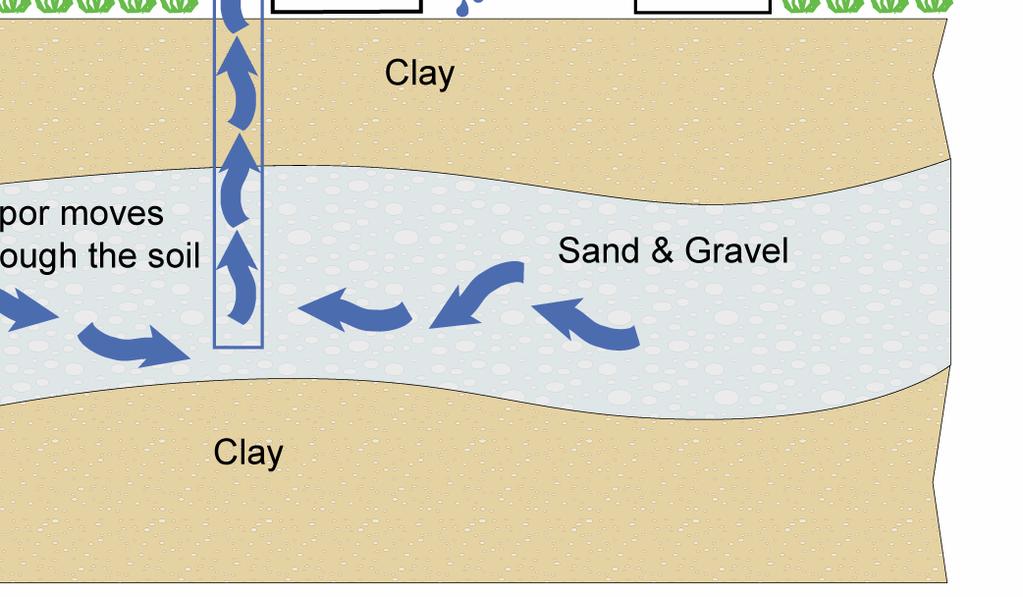
10 In-Situ Steam Generation ELECRODE <15 V NEURAL ELECRODE 150 V to 600 V HEAED ZONE 1. Soil grains act as electrical resistors 2. Steam generation is uniform through the heated zone 3. Discrete intervals can be heated

11 Surface Equipment 500 kw PCU Air Cooling ower Emergency Shutoff Steam Condenser Skid Photo Courtesy of Brown and Caldwell Operating Electrode
12


13

14 ERH Remediation Beneath a Building Limited overhead access Electrode Co-located w/ Recovery Well Vapor Recovery Line Photo Courtesy of Brown and Caldwell Electrode

15 ERH Remediation Beneath a Building Limited overhead access Electrode Co-located w/ Recovery Well Vapor Recovery Line Photo Courtesy of Brown and Caldwell Electrode

16
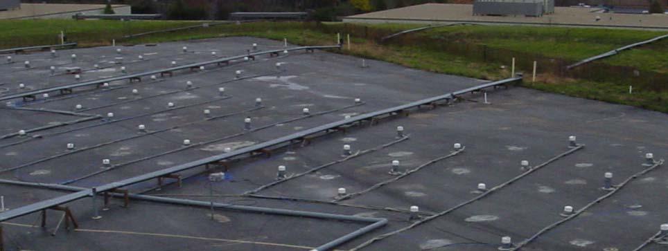
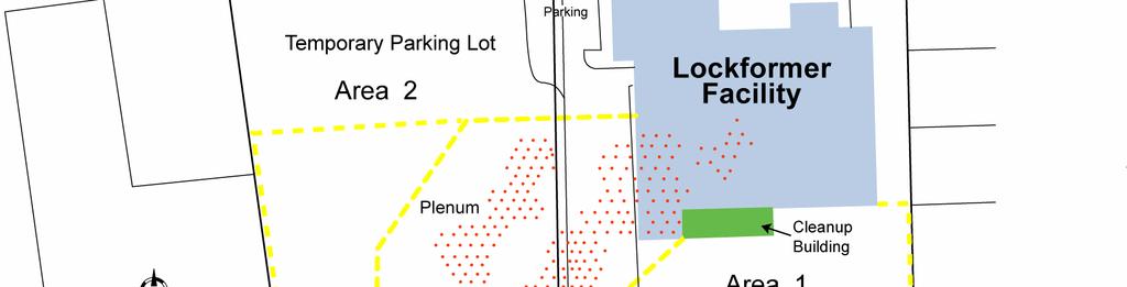
17 ERH Plenum AREA 2 PLENUM AREA 1 PLENUM R of 16

18 Insert Picture of Plenum Construction or Picture of Electr Installation from Western Springs Site


19

20 Electrode Locations for ERH System in Upper ill Insert Plate R-4 from ech Memo Diagrams

21
22
23

24
25 ERH and SVE Overlay AREA 2 AREA 1 R-5 5 of 16
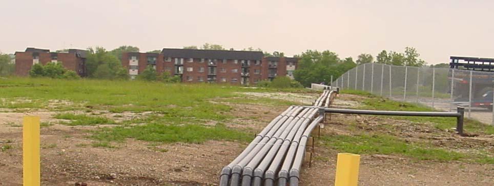
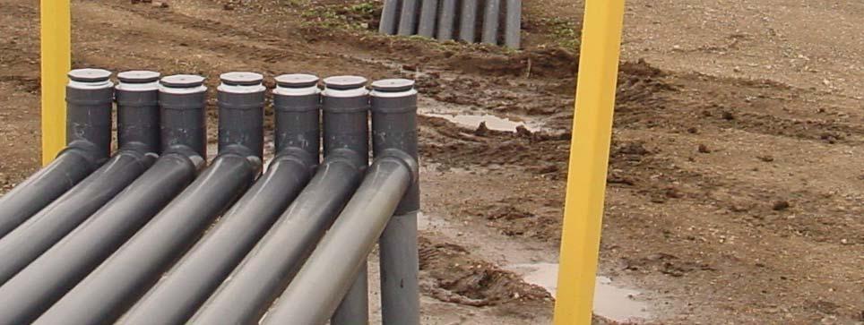
26 Recovery System AREA 1 PLENUM
27 Requirements of the Administrative Order Clean-up objectives for CE in the upper till were set at 8.9 ppm (IEPA ACO Industrial Worker Inhalation Standard). Installation of plenum with vapor recovery system. Installation of temperature monitoring points Operation of the ERH in conjunction with the SVE system to eliminate vapor migration vertically or horizontally
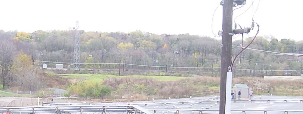
28 Requirements of the Order Vapor recovery and Granular Activated Carbon reatment of the vapor phase and collected water. Continuous Air Monitoring of stack emissions and site work zone and perimeter monitoring is required due to the close proximity of residences.

29 otal Hydrocarbon Analyzer
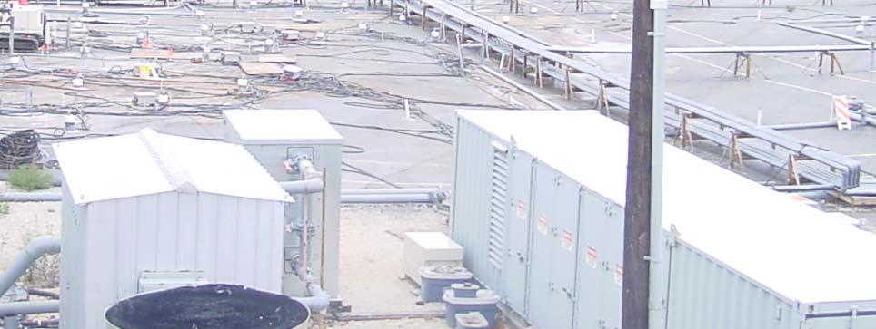
30 ERH and SVE Vapor reatment System
31 Regulatory Requirements Granular Activated Carbon reatment of the recovered vapor and collected water prior to discharge. Continuous Air Monitoring of stack emissions and site work zone and perimeter and residential samples were required due to close proximity of residences.


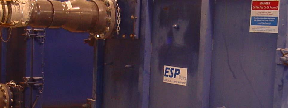
32 Roll-Off Box with Granular Activated Carbon

33

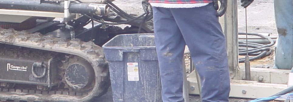
34 Confirmation Sampling
35 Lockformer Case Study Clean-up objectives for the upper clay till of 8.9 ppm (IEPA ACO Industrial Worker Inhalation Standard) have been met at 95% of the site. (average concentrations are less than 1ppm for CE Installation of plenum with vapor recovery system temperature monitoring points he Off Gas Carbon reatment System has been effective, no vapor release detected Operation of the ERH in conjunction with the SVE system has eliminated vapor migration vertically or horizontally
36 Conclusions he use of ERH in conjunction with SVE to treat CE contaminated soil in-situ has been operational since February of Approximately 95% of the site has been remediated below 1ppm CE he design and construction of temperature and vapor monitoring probes was required to evaluate movement of the vapor phase Air monitoring of stack emissions, site work zones, perimeter and residential have shown no exeedances of health standards.
37 Conclusions (cont.) ERH technology is capable of treating soil with low permeability and with high concentrations of chlorinated solvents Other potential uses include; petroleum contaminated soil, other volatile and semi-volatile compounds
38 ERH Costs Contract with hermal Remediation Systems ($ 3.1 Million) Electrical usage $330,000 Approximate cost/yard = $100 to $120 Current Landfill costs were $200/ton Some high level CE soils require pretreatment prior to disposal at a landfill