Long term plans for MYRRHA In view of a future ADS
|
|
|
- Flora Parker
- 5 years ago
- Views:
Transcription

1 Long term plans for MYRRHA In view of a future ADS Hamid AÏT ABDERRAHIM Director of MYRRHA Project haitabde@sckcen.be or myrrha@sckcen.be 4 th WS Energy for Sustainable Science at RI, November 17-18, 2017 Magurele (RO)
2 Outline Some facts & questions on sustainability & energy What is & why MYRRHA MYRRHA Accelerator Specific requirements Pre-Licensing & Licensing status MYRRHA & P&T Phased implementation & high level planning Conclusion 2

3 Energy challenges : geopolitical considerations Who has the oil? 3

4 Energy challenges : correlation energy routes / armed conflicts 4


5 Energy challenges : What s the colour of electricity? Green? Red? Blue?... White or Dark 5
6 Energy challenges : Will the energy saving, save the world? Pop. OECD (mio) Energy Demand (oet/cap.) Total Energy Consumption OECD (mio oet) Pop. Non-OECD (mio) Energy Demand (oet/cap.) Total Energy Consumption Non-OECD (mio oet) TOTAL CONSUMPTION (mio oet)
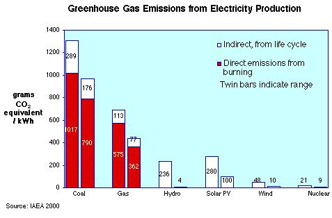


7 Energy challenges : invest in all CO 2 non-emitting energy sources including nuclear energy 7
, Integration costs of wind power can be in the same range as generation costs Data for Germany estimates integration cost of EUR 50-60 / MWh from wind Impact on")
8 Electricity cost increases with increased wind & solar penetration, to stabilize the grid (German data) Cost of Electricity System LCOE of Wind in Germany Comments Integration costs of VRE: Even at moderate wind penetration (~20%), Integration costs of wind power can be in the same range as generation costs Data for Germany estimates integration cost of EUR / MWh from wind Impact on assessing energy mix: Significant driver are profile costs, esp. reduced utilization of stable base-load plants (nuclear and thermal plants) by volatile wind power Integration costs can become an economic barrier to deploying VRE at high shares Economic evaluation of wind and solar power must not neglect integration costs Market Value of Variable Renewables decreases with increasing share in the energy mix Source: System LCOE: what are the costs of Variable Renewables? by F. Ueckerdt, L. Hirth, G. Luderer, and O. Edenhofer, Working Paper first published January
9 Electricity prices in Europe (especially Germany) indicate Variable Renewables come at a cost: grid stability Household electricity prices (EUR/kWh) 0,35 Industry electricity prices (EUR/kWh) 0,16 0,30 0,25 0,20 0,15 0,10 0,05 0,00 VRE* penetration: BE (%) DE (%) DK (%) 08 H1 0,7 7,0 17,6 09 H1 1,3 8,3 19,2 10 H1 2,1 9,0 20,5 11 H1 3,5 11,0 23,8 12 H1 5,2 12,6 26,3 13 H1 EU-28 Belgium Germany Denmark 6,7 13,9 31,0 14 H1 +25% H1H2 Note: *VRE = Variable Renewable Energy sources, i.e. Wind and Solar Source: Eurostat Electricity price statistics (May 2016), Eurostat SHARES 2014 for VRE penetrations , OECD / IEA Electricity 2016 edition for VRE penetration ,0 16,1 36,2 12,5 19,4 51,3 0,14 0,12 0,10 0,08 0,06 0,04 0,02 0,00 08 H1 0,7 7,0 17,6 09 H1 1,3 8,3 19,2 10 H1 2,1 9,0 20,5 EU-28 Belgium Germany Denmark 11 H1 3,5 11,0 23,8 12 H1 5,2 12,6 26,3 13 H1 6,7 13,9 31,0 14 H1 8,0 16,1 36,2 +38% H1H2 12,5 19,4 51,3 9 9


10 Key technical objective of the MYRRHA-project: an Accelerator Driven System MYRRHA An Accelerator Driven System Demonstrate the ADS concept at pre-industrial scale Can operate in critical and sub-critical modes Demonstrate transmutation Fast neutron source multipurpose and flexible irradiation facility Target main reaction spallation output n/s material LBE (coolant) Accelerator particles protons beam energy 600 MeV beam current 2.4 to 4 ma Reactor power 65 to 100 MW th k eff 0,95 spectrum fast coolant LBE 10
11 MYRRHA Present status Source: 12

12 Pool-type: MYRRHA rev. 1.6 at the End of 2014 Size reduction Po issue O 2 concentration control Optimisation requested 13


13 Option 0-D: evolution of existing design with innovative heat exchangers Layout of main components 14
 Option Reactor type Description 0 Pool Updated rev. 1.")

14 MYRRHA reactor design update Four MYRRHA primary system design options investigated to reduce the dimension of the reactor vessel (& associated cost) Option Reactor type Description 0 Pool Updated rev. 1.6 Innovative IVFHM & double-walled PHX 1 Pool Reduced size Innovative IVFHM & double-walled PHX Option 0 is now the reference design under further optimisation 2 Loop Bottom loading Existing IVFHM concept & external doublewalled PHX 3 Loop Top loading 15

15 MYRRHA linac: Design frozen since

16 Masterplan 100 MeV ~ 125 m Proton Target Facility Auxiliaries ~ 125 m Beam line RF-gallery Cryogenics Front-end building 17

17 Building architecture Level 00 open facility user accessible targets technical working area LINAC injector accelerator utilities strict access control Major source term 18

18 Building architecture Front views front-end building sand shielding PTF accelerator utilities building 19

19 Masterplan Full MYRRHA ~ 500 m ~ 200 m REACTOR BUILDING LINAC FRONT- END 20
20 MYRRHA Accelerator specific requirements Source: 21
 Proton energy 600 MeV Beam current Repetition rate 0.1 to 4.")


21 22 Specific requirements of MYRRHA Accelerator High power proton beam (up to 2.4 MW) Proton energy 600 MeV Beam current Repetition rate 0.1 to 4.0 ma CW, 250 Hz Beam duty cycle 10-4 to 1 Beam power stability Beam footprint on reactor window Beam footprint stability # of allowed beam trips on reactor longer than 3 sec # of allowed beam trips on reactor longer than 0.1 sec # of allowed beam trips on reactor shorter than 0.1 sec < ± 2% on a time scale of 100ms Circular 85mm < ± 10% on a time scale of 1s 10 maximum per 3-month operation period 100 maximum per day unlimited Extreme reliability level: MTBF > 250 hrs 22
22 Roadmap to Reliability Design Major accelerator labs in Europe as well as specific industrial partners Incorporating fault tolerant schemes Validation with reliability model Reviewed by panel of international accelerator peers Prototyping Key elements: Ion source, LEBT, RFQ, CH cavities, etc. Set-up of an experimental test-bench: 5.9MeV UCL in LLN Hands-on experience for the team, return on experience for manufacturing phase, start of engineering work in view of the construction and integration Scenario 1 100MeV Representative unit in view of the 600MeV Implementation of fault tolerant schemes Testing and validation of technological choices Evaluation of the reliability goal for the full MYRRHA Linac Applications (Lucia s presentation) 23
23 Accelerator components Ion source LEBT Chopper RFQ CH NC cavities Single spoke cryomodules Elliptical cryomodules 24
24 Ion source LEBT Chopper 25

25 RFQ Radiofrequency quadrupole First accelerating structure 4--rod 30keV 1.5MeV 176.1MHz 4m long aluminium structure Stems: OFHC Copper &Thick copper plating Complex water cooling system 26
26 CH room temperature cavities Second accelerating section 1.5MeV 17MeV 176.1MHz Stainless steel structures Thin copper plating 27

27 Single spoke cavity cryomodules 28

28 Single spoke cavity 29


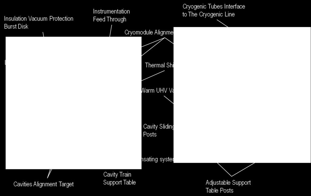
 200 600MeV: elliptical")
 2 cavity cryomodules: ~ 3m")
29 Elliptical cavity cryomodules Fourth and fifth accelerating section 100MeV 600MeV Superconducting RF structures MeV: double spoke or elliptical cavities (352.2 or 704.4MHz) MeV: elliptical cavities (704.4MHz) 2 cavity cryomodules: ~ 3m long 4 cavity cryomodules: ~ 8m long 30
30 Pre-Licensing & Licensing status Source: 31
31 Large effort devoted to pre-licensing / licensing Since 2010 contractual relation with FANC/Bel-V (BE licensing authority and its TSO) for pre-licensing of MYRRHA ADS, resulted in: 4 design guidelines DOPF (Design Option Provisions file) in 4 volumes 57 focus points identified At end of March 2017 Design guidelines (seismic, aircraft crash, flooding, safety approach) applied in design version 1.6 DOPF : 4 volumes produced and submitted to FANC (V1&2 iterated already 2 times) 167 Deliverables produced and submitted to FANC/Bel-V (addressing the 57 FCs): iterative process each deliverable requesting 2 to 3 iterations) : 70% iterated First opinion on licensability expected between Sept. Dec Licensing of MYRRHA Accelerator 100 MeV started in
32 MYRRHA & P&T Source: 33


33 MYRRHA R&D applications portfolio SNF*/ Waste Fission GEN IV Multipurpose hybrid Research Reactor for High-tech Applications Fusion Fundamental research *SNF = Spent Nuclear Fuel Radio-isotopes SMR LFR Source: SCK CEN MYRRHA Project Team, MYRRHA Business Plan 34


34 Transmutation is the better solution for Spent Nuclear Fuel SNF 1000 transmutation of spent fuel spent fuel reprocessing no reprocessing ~300 year +10,000 year +300,000 year Natural Uranium 1 *SNF = Spent Nuclear Fuel Duration Reduction 1.000x Volume Reduction 100x Source: European Commission Strategy Paper on Partitioning & Transmutation (2005), SCK CEN MYRRHA Project Team 35
: here U&Pu is removed from the spent fuel Disposal: Superficial for LLW and ILW (half lives ~10 3 yrs) Geological for")
: To reduce radiotoxicity of MAs, we can to fission them The ratio Fission/Capture is more favorable")
35 Partitioning & Transmutation Spent nuclear fuel current EU strategy is: Onsite in-pool or dry storage Reprocessing in (few) centralized and dedicated plants (1yr): here U&Pu is removed from the spent fuel Disposal: Superficial for LLW and ILW (half lives ~10 3 yrs) Geological for HLW (half lives ~ 10 6 yrs) Storage ( to wait ) vs. treatment ( to use nature against nature ): To reduce radiotoxicity of MAs, we can to fission them The ratio Fission/Capture is more favorable with fast neutrons To reduce radiotoxicity of LLFPs, they should undergo several neutron captures 36
36 Three options for Minor Actinide transmutation Studied in ARCAS FP7 project EU is presently considering two approaches for transmutation: via FR or ADS FR heterogeneous FR homogeneous ADS Driver fuel Blanket with MA Fuel with MA Blanket Fuel with MA Core safety parameters limit the amount of MA that can be loaded in the critical core for transmutation, leading to transmutation rates of: FR = 2 to 4 kg/twh ADS = 35 kg/twh (based on a 400 MW th EFIT design) 37

37 Even with completely different national NE policies European solution for HLW works with ADS Spent fuel A Reprocessing A Reprocessing B Pu + MA MA ADS fuel fabrication Pu + MA ADS fuel reprocessing ADS Spent fuel ADS GROUP A SHARED REGIONAL FACILITIES Advantages for A ADS shared with B ADS burn A s Pu& MA Smaller Fu-Cycle units & shared Pu MOX Fabrication UOX Fabrication Enriched U PWR MOX PWR UOX Spent fuel B GROUP B Scenario 1 objective: elimination of A s spent fuel by 2100 A = Countries Phasing Out, B = Countries Continuing Advantages for B ADS shared with B ADS burn B s MA A s uses B s Pu (part) as resource in FR FR fleet not contam with MA s Smaller Fu-Cycle units & shared 38
38 Phased implementation & high level planning Source: 39


39 Phase MeV Phase 3 Reactor Phase MeV MYRRHA s phased implementation strategy LEBT 0.03 MeV 1.5 MeV 5.9 MeV RFQ RT-CH sec on SC-CH sec on 17 MeV MEBT 70 kw dump # MeV Spoke linac MHz 48 cav., l=73 m Benefits of phased approach: RT-CH cavity SC-CH cavity #2 Reducing technical risk Spreading investment cost LEBT 4-rod RFQ thermal mockup SC-CH cavity spoke cryomodule single spoke cavity power coupler cold tuning system First R&D facility available in Mol end of element ellip cal cavity ellip cal cavity envelope with cold tuning mechanism design of the test cryomodule for the ellip cal cavity 700 MHz Solid State RF amplifier prototyping Source:SCK CEN MYRRHA Project Team 40

40 Phased implementation plan MYRRHA Project ( ) > Implementation High-Level overview 1 st Facility at Mol in 2024 Source: SCK CEN MYRRHA Project Team Phase 1: Phase 2&3:
41 Conclusions ADS is not anymore an Emerging Nuclear Energy System It has accomplished many impressive progresses in various fields, thanks to MYRRHA: Accelerator technology Pb and Pb-Bi technology HLM instrumentation (O 2 -meters, Flow meters, US-Visu, Sub-criticality monitoring, etc ) Material behavior in HLM (corrosion, erosion LME, etc ) ZPR experiments (FEAT/TARC, MUSE, YALINA, GUINEVERE, ) Large Scale HLM reactor mock-ups (ESCAPE, CLEAR-S) What is then the danger for this technology? Not to succeed to cross the valley of death for moving from R&D enthusiasm compensating small money to preindustrial scale needing large money, rigorous industrial approach and severe safety and licensing judgement 42
42 A jump in the future for pioneering innovation in Europe Through a pan-european Reasearch Facility in Belgium For turning a safe, clean and concentrated energy source into: A sustainable & safer energy for humanity in a cleaner environment 43
43
44 Copyright SCK CEN PLEASE NOTE! This presentation contains data, information and formats for dedicated use ONLY and may not be copied, distributed or cited without the explicit permission of the SCK CEN. If this has been obtained, please reference it as a personal communication. By courtesy of SCK CEN. SCK CEN Studiecentrum voor Kernenergie Centre d'etude de l'energie Nucléaire Belgian Nuclear Research Centre Stichting van Openbaar Nut Fondation d'utilité Publique Foundation of Public Utility Registered Office: Avenue Herrmann-Debrouxlaan 40 BE-1160 BRUSSELS Operational Office: Boeretang 200 BE-2400 MOL 45