Environmentally Sound Technology Biomass Fuelled Energy Plants. Combined Heat and Power Supply. Biomass Fired Steam Generator
|
|
|
- Andrea Fleming
- 5 years ago
- Views:
Transcription
1


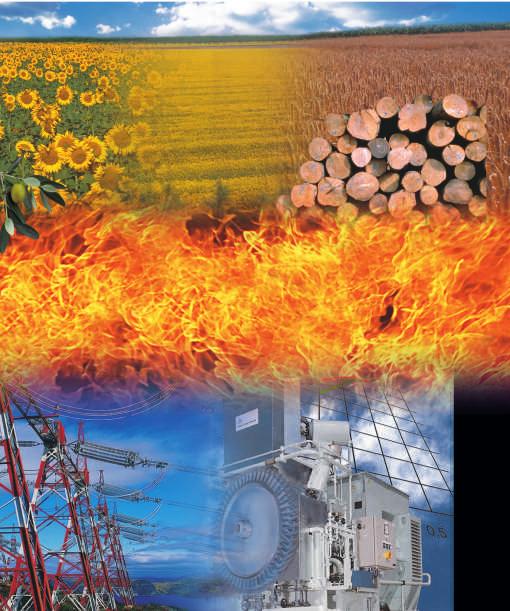
2 Environmentally Sound Technology Biomass Fuelled Energy Plants BONO SISTEMI can boast 50 years experience, gained in the design and production of biomass fired steam generators and thermal fluid heaters using a variety of waste fuels such as olive husks, rice husks and wood chips, with more than 42 installations worldwide. The BONO technology fields of application in the biomass fuelled plants are in the process industry and particularly the food and wood industries, where the production wastes, such as wood chips, saw dust, rice husks, olive husks etc, represent a free of charge fuel to produce both heat to the process and electric power. Up to 10 MWel Another important and high demand field is district heating, in locations where biomass is easily available and can represent a competitive alternative to fossil fuel. Moreover, being active since over ten years in projects financed by United Nations Organisations in compliance with the Sustainable Development programs, BONO SISTEMI has got unique skills in carrying out projects for the substitution of Ozone Depleting Substances (according to the Montreal Protocol recommendations) and for the application of the Kyoto Protocol on the greenhouse gases global reduction (CDM and JI projects). Up to 54 MWth Power to the grid Steam turbine Biomass Fired Steam Generator Process Heat Combined Heat and Power Supply Biomass Fired Thermal Oil Heater The BONO SISTEMI biomass fuelled plant is the heart of an energy system able to generate pure heat for industrial processes, district heating for small and medium communities, and electrical power if coupled to power generators such as steam engines and turbines, or other devices. When the two purposes are jointed we then talk about CHP plant (Combined Heat and Power plants). Thanks to consolidated experience in the energy field BONO SISTEMI engineering is able to study and design full turn-key plants starting from the greenfield. ORC turbine District Heating Up to 2 MWel Up to 10 MWth Power to the grid


3 The Reciprocating Grate Combustion System Reciprocating grate is state of the art combustion technology suitable for any kind of biomass ranging from: High moisture content one, as for dump wood waste or virgin wood Biomass mixture Dusty biomass, as for olive residues Low specific gravity ones, as for rice husk Let's follow the biomass path through the combustion system. The fuel, coming from the storage area, is fed into a loading hopper, being an intermediate and constant biomass volume upon the fuel feeder. The hopper design prevents clogging due to entrance of irregular pieces, and is equipped with control level and fire fighting system. The structure is simply air cooled thanks to the choice of refractory Ni-Cr cast steel bars composing each row, for high thermal and mechanical resistance also in case of power black out. The bars keep moving the biomass and assure its intimate contact with the combustion air. The wide surface available allows a margin in case of incorrect operation or quick change of fuel characteristics. From the hopper the fuel passes into the fuel feeder. It is a linear hydraulically driven drawer, water cooled, with the front end covering the full width of the chamber and able to distribute uniformly the biomass on the grate. The coverage of the grate is mandatory and always achieved. The multiple stroke actuator gradually pushes forward the biomass according to the combustion demand. The fuel is now on the reciprocating grate. It is a walking inclined floor, with alternative fixed and movable rows hydraulically driven. The grate is divided in three or four zones, depending on the plant size, respectively for drying, combustion and burn out of the fuel. The bars speed movement and the combustion air flow are independently programmable for each single section in order to compensate different biomass composition, to perform the proper residence time and to adequate the boiler load. Ashes are automatically removed by reciprocating action of the grate and collected at its end into a specific hopper and moved out through an automatic conveyor. The primary combustion air is independently injected underneath each zone and is pre-heated for high moisture biomass combustion. The high speed secondary air, together with recirculated flue gas, are distributed over the combustion chamber to generate high turbolence. In this way low NOx emissions and good mixing of flue gas for combustion completion are achieved. Further more alternative combustion system technologies are available: Screw burners, suitable for uniform and small size biomass up to 10mm having moisture content below 15% wt. Blow burners, suitable for handling powder biomass. Fixed grate, suitable for very low specific gravity biomass as for sunflower husks and rice husks

4 Biomass Fired Water Tube Steam Generator Biomass Fired Thermal Oil Generator Large combustion chamber made of refractory brick walls to assure adequate residence time at high temperature for combustion completion. Patented heater design. Horizontal multi-tubular-parallelepiped heater with square cross section. Radiant section made of tangent tubes welded to distribution headers, and convective section made of wide spaced bent tubes banks. The BONO patented parallelepiped heater has been designed to assure extended exchange surfaces, to assure uniform thermal oil circulation and to prevent tubes from clogging, granting high efficiency reliability and availability. The parallelepiped heater is complete with fouling cleaning system by means of soot blower. Combustion chamber made of membrane water tube walls protected by a refractory liner against corrosion, erosion and severe high temperature environment. Wide furnace volume for optimised combustion and low specific thermal load. Secondary combustion air distribution and flue gas recirculation generating turbulence to ensure complete flue gas mixing and combustion efficiency. Integrated non catalytic NOx reduction system. Geometry of the flue gas path in the boiler is designed to reduce the speed and thus erosion and fouling phenomena on the tubes. Convective section with evaporating section with drums, superheater, pre-heater, economiser and air pre-heater according to process characteristics. Hoppers are placed along the boiler for ash collection. Hopper for ash collection. Package heater configurations ready to be placed on combustion chamber. BONO water tube steam generator configuration allows to achieve these important results: High efficiency 84-85% Reduced fouling High availability hours/year Simple inspection and maintenance Low thermal inertia for quicker cooling down and heating up of boiler. Reduced CO and NOx emissions

5 Engineering, Manufacturing, Assembly and Start Up A biomass fuelled energy plant project originates as a delicate balance of technical and economical requirements. BONO SISTEMI offers the support in the very early analysis of the project, developing with the customer the different options up to the final solution. We are able to customize the energy plant, to choose and provide the flue gas treatment system, the water treatment system, the power generator and ancillaries, as well as the civil works up to a full turn-key supply. Our three workshops in Italy manufacture all the pressure parts and steelworks according to the main European and American codes. The plant parts are then delivered pre-assembled in modules according to transportation limitations and installed on-site under the responsibility of a dedicated team of skilled site managers, up to the final commissioning and start-up.


6 Biomass Fired Thermal Oil Heater Wedge floor silo Feeding conveyor Combustion system Thermal Oil Heater Air Heater + ECO Cyclone Flue gas treatment Chimney Ash conveyors Model BIO-OIL 3 BIO-OIL 5 BIO-OIL 7 BIO-OIL 10 BIO-OIL 12 Thermal capacity 3,5 MW 5 MW 7 MW -10 MW 12 MW T in / T out 250 : 310 C 250 : 310 C 250 : 310 C 250 : 310 C 250 : 310 C Air pre-heater Soot Blowing Process Direct Heat ORC +DH 0,6 MWe + 2,8 MWth 1 MWe + 4 MWth 1,3 MWe + 5 MWth 1,8 MWe + 7,7 MWth 2 MWe+, MWth


7 Biomass Fired Water Tube Steam Generator Wedge floor silo Feeding conveyor Combustion system Steam generator Economizer Cyclone Flue gas treatment Chimney Ash conveyors Model SH 7,5 SH 15 SH 22,5 SH 30 SH 37,5 SH 45 Model SAT 3,5 SAT 7 SAT 10 SAT 14 Thermal capacity 7,5 MW 15 MW 22,5 MW 30 MW 37,5 MW 45 MW Thermal capacity 3,5 MW 7 MW 10 MW 14 MW Superheated Steam 10 t/h 20 t/h 30 t/h 40 t/h 50 t/h 60 t/h Saturated Steam 5 t/h 10 t/h 15 t/h 20 t/h Pressure up to 50 bar up to 50 bar up to 50 bar up to 50 bar up to 50 bar up to 50 bar Pressure up to 30 bar up to 30 bar up to 30 bar up to 30 bar Temperature up to 450 C up to 450 C up to 450 C up to 450 C up to 450 C up to 450 C Efficiency up to 87 % up to 87 % up to 87 % up to 87 % Efficiency up to 87 % up to 87% up to 87% up to 87% up to 87% up to 87% Economizer Economizer Air pre-heater Electrical Power 2 MW 4 MW 6 MW 8 MW 10 MW 12 MW Direct Process Heat
8