GEO-flow Pipe Leaching System Specifications & Features. Design & Installation Manual Indiana
|
|
|
- Brooke Potter
- 5 years ago
- Views:
Transcription


1 GEO-flow Pipe Leaching System Specifications & Features Design & Installation Manual Indiana
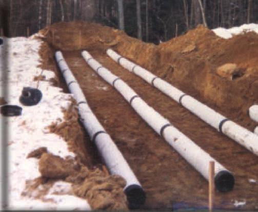
2 Contents I. Introduction 2 II. The GEO-flow Pipe Leaching System 3 III. GEO-flow Pipe Leaching System Specifications 4 IV. Geo-flow Pipe Leaching System In Ground Single Pipe Schematic 5 V. Basic Design Considerations 5 VI. Indiana State-Specific Considerations 6 VII. Designing the GEO-flow Pipe System 9 VIII. Installation Instructions 12 IX. System Configurations 13 X. Appendix I - Installation Report Form 18 XI. Appendix II - Inspection Checklist 19 I. Introduction The purpose of this manual is to provide the minimum design and installation information for the use of the GEO-flow Pipe Leaching System in the State of Indiana. Any exceptions or changes to the design or procedures must be confirmed by ADS, Inc. and the Indiana State Department of Health. Any revised version of this manual supersedes all previous versions. This manual provides a brief description of the GEO-flow Pipe Leaching System and its applications in Indiana. For more information, or for answers to questions or concerns, please call our Midwest Zone office at the number listed below, or contact your local sales representative. The GEO-flow Pipe system is an advanced alternative to the stone and pipe components of a conventional effluent disposal system. The GEO-flow Pipe product is fabricated at our plants using ADS manufactured corrugated polyethylene pipe. This large-diameter pipe is encased in a symmetrical polypropylene grid, which is then wrapped in a specifically designed geotextile. This patented design, when installed in 6 inches of specified system sand, creates a system that is significantly more efficient than conventional pipe and stone. GEO-flow Pipe is lightweight, and does not require the use of stone. Therefore, it may be delivered to and constructed in areas where conventional pipe and stone systems would be difficult to install. GEO-flow Pipe has been used successfully for more than 20 years for both residential and commercial installations. System designers can specify GEOflow Pipe with confidence in the knowledge that the GEO-flow Pipe product they install in each and every system will be fully backed by ADS. ADS, Inc. 288 Lafayette Street, London, Ohio

3 II. THE GEO-flow PIPE LEACHING SYSTEM Each GEO-flow Pipe Leaching System is comprised of the following components: Complete 10 GEO-flow pipe sections Offset adapters End caps Couplers System sand 1. GEO-flow Pipe Sections GEO-flow Pipe sections come in 10-foot lengths. Each section is comprised of the following: ADS manufactured corrugated high-density polyethylene pipe. This pipe is perforated to allow for effluent to pass through its sidewalls easily and at varying heights. This pipe is encased in a: Symmetrical polypropylene grid, which is wrapped in a: Specially designed, non-woven plastic geotextile fabric. The GEO-flow Pipe sections function in a number of ways. The geotextile fabric establishes a distinct surface at which bacterial growth and activity will take place. This material will restrict the flow of effluent leaving the corrugated pipe, and biomat will naturally occur on its surface as a result. In addition, the large-diameter corrugated pipe creates a dispersal medium where effluent introduced into the system is constantly changing elevations. This changing of elevations encourages and enhances the bacterial activity within the biomat, thereby maximizing its function. The large diameter pipe also serves as a repository for suspended solids that may inadvertently exit the septic tank. Finally, the polypropylene grid between the pipe and the fabric creates a substrate for bacterial communities while aiding in the distribution of effluent around the entire circumference of the pipe. 2. Offset Adapters Offset adapters are end caps fitted with a 4-inch offset hole at the 12 o clock position. 3. End caps End caps are molded to fit snugly on the end of any GEO-flow Pipe section to close the line. 4. Couplers Internal couplers fit within the ends of two GEO-flow Pipe sections to create a GEO-flow pipeline. 5. System Sand All GEO-flow Pipe Leaching Systems installed in Indiana require a minimum of six inches (6 ) of system sand surrounding the entire circumference of the pipe. In raised system applications, an additional six inches (6 ) of system sand must be added below the pipe to create a minimum of 12. System Sand : System sand shall meet INDOT Specification 23 sand requirements. Surrounding Backfill Material: Material around the remainder of the system may be either additional system sand or material that meets the requirements of ISDH 410 IAC The top sixinches (6 ) of any system shall be comprised of cover material that will sustain plant growth. Bed Material: Beds designed and installed on level sites require the system sand area to extend a minimum of one foot (1 ) around the perimeter of the GEO-flow pipe bed. For beds designed and installed on sloped sites, the system sand on the downslope side of any system placed on sites with >1/2% to 10% slope must extend at least threefeet (3 ) from the edge of the lowest pipe; and the system sand on the downslope side of any system placed on sites with greater than 10% slope must extend at least five-feet (5 ) from the edge of the lowest pipe. 2
4 III. GEO-FLOW PIPE LEACHING SYSTEM SPECIFICATIONS Scope This specification describes GEO-flow available in 10- inch (250 mm) inside diameter pipe for use in on-site waste disposal applications in Indiana. Pipe Requirements GEO-flow pipe shall meet the requirements of ASTM F667. It shall have a corrugated interior and exterior. There shall be eight 7/16 inch (9.5 mm) holes evenly spaced 45 degrees apart per corrugation continuing the full length of the pipe. The pipe shall be shipped with a pre-installed reinforcing geo-grid fabric and 4 ounce geotextile fabric. Joint Performance Pipe shall be joined with internal couplers covering at least two full corrugations on each end of the pipe. Material Properties Pipe material shall be high density polyethylene conforming to the minimum requirements of cell classification C as defined and described in ASTM D3350. Geo-Grid Fabric Min. Tensile Strength: ASTM D4595; 400 lb/ft. Min. Transmissivity: ASTM D4716; 1 x 10⁻³ m2/sec 1 and vertical load: 10,000 psf Min. Density: ASTM D1505; g/cm3 Typical Melt Flow Index: ASTM D1238; 1.0 g/10 min. Min. Carbon Black Content: ASTM D4218; 2 % Min. Thickness: ASTM D5199; 5.0 (200) mm/(mil) Min. Unit Weight: ASTM D3776; 20 oz/sy 4 oz. Geotextile Property Specification Fiber: Polyester Substrate: None Weight: 4.0 oz/yd2 +/ oz/yd2; FTM NW503 Thickness: inch +/ inch; FTM NW504 Tensile Warp: 52 lb. min.; FTM NW505 Tensile Fill: 68 lb. min. System Sand: System sand shall meet INDOT Specification 23 sand requirements. 3
5 IV. GEO-FLOW PIPE LEACHING SYSTEM IN GROUND SINGLE PIPE SCHEMATIC Finish Grade Top Soil INDOT Specification 23 Sand GEO-flow Pipe GEO Grid Fabric 6" Pipe Original Soils Original Soils 6" 6" Original Soils V. BASIC DESIGN CONSIDERATIONS General Considerations Common design practices shall apply. These include, but are not limited to: Product should be designed to be installed on a level plane; Product must be designed to run parallel to contours; Longer (rather than shorter) product lines are recommended; minimum and maximum lengths shall be designed in accordance with ISDH 410 IAC 6-8 and these instructions; The inlet of the outlet of the distribution box shall be at least 2 inches above the highest invert of any GEO-flow Pipe line in the system. Indiana Rules Details of the design and installation of the GEO-flow Pipe Leaching System shall be in accordance with all requirements of ISDH 410 IAC 6-8.2, et seq., unless specifically addressed in this manual. 4
6 VI. INDIANA STATE-SPECIFIC CONSIDERATIONS Any and all information in this manual is to be used in conjunction with the Indiana State Department of Health Rule 410 IAC 6-8.2, and all other State and local regulations. Cover Requirements The minimum depth of cover for each GEO-flow Pipe System is twelve inches (12 ), comprised of six inches (6 ) of system sand plus a minimum of six inches (6 ) of cover material. Piping All piping that runs between the distribution box and the GEO-flow pipe in the GEO-flow System must be ISDH approved PVC piping or consistent with piping as specified in Rule 410 IAC Installer, Designer, & Health Department Personnel Certification Approval of the GEO-flow Pipe Leaching System in Indiana includes a requirement that all installers and designers of the GEO-flow Pipe Leaching System, as well as local health department personnel who review and approve plans and conduct inspections, be trained and certified by an authorized ADS/Hancor representative. Separation Distances All horizontal separation distances as articulated in 410 IAC , and all vertical separation requirements as articulated in 410 IAC and 410 IAC shall be met. Vertical separation distance in systems comprised of multiple beds shall be determined based upon the design flow of the individual beds. Vertical and horizontal setback distances are measured from the outer aspect of the system sand. Sloped Systems In accordance with 410 IAC (2) and (2), the maximum amount of slope allowed on the site for installation of the GEO-flow Pipe Leaching System is as follows: subsurface: 15%; above grade: 6%. A site shall be considered to be sloped when the grade is greater than one-half percent (1/2%). When installed on a sloped site, all GEO-flow systems shall utilize serial distribution. Parallel distribution is prohibited. Subsurface Systems A GEO-flow Pipe Leaching System shall be considered subsurface when the system sand/native soil interface (infiltrative surface) is a minimum of four-inches (4 ) below original grade. Maximum Depth In accordance with 410 IAC (j), the maximum depth from original grade to the bottom of the GEO-flow Pipe Leaching System sand shall not be more than thirty-six (36) inches for new construction. Minimum System Size All GEO-flow Pipe Leaching Systems shall include a minimum basal area, comprised of system sand, of at least 350 square feet (350 ft2). Length to Width Ratio Long and narrow is preferred in the design of bed systems. Subsurface Drainage/Surface Diversions Subsurface drains and surface diversions may be utilized with the GEO-flow Pipe System. Design and installation shall be in accordance with 410 IAC Departmental Approval All Geo-Flow Pipe Leaching System designs for soils with a load rate of equal to 1.2 gallons per day per square foot must be reviewed and approved by the Indiana State Department of Health prior to permit issuance by the local health department. Observation Ports ISDH approval of the GEO-flow Pipe System requires that each system (or each bed in a system comprised of more than one bed) shall include an observation port. The bottom 18 of a 4-inch PVC pipe must be pre-drilled and wrapped in filter fabric. This pipe must be (1) installed to the base of the system sand, (2) extend beyond final grade, and (3) be capped. In sloped system applications, the observation port shall be located on the downslope side, within 12 of the end of the system sand taper. Parallel distribution may be utilized only on level sites. 5
7 System Installation Report Form Certified installers must complete a GEO-flow Pipe Leaching System Installation Report Form for each system installed, and submit this completed form to ADS. Please see a copy of this form, with instructions, at the back of this manual, labeled Appendix I. Additional Considerations Any and all information in this manual is to be used in conjunction with the Indiana State Department of Health Rule 410 IAC and all other state and local regulations. Inspection Checklist Certified designers must provide the system owner with a copy of the GEO-flow Pipe Leaching System Inspection Checklist at the time of system purchase. Please see a copy of this document at the back of this manual, labeled Appendix II. SOIL TEXTURE CLASSES Single Grain Granular Platy* Table V Soil Loading Rates for Subsurface Systems (in gpd/ft2) SOIL STRUCTURE CLASSES Strong: Angular, Subangular Blocky Moderate: Angular, Subangular Blocky Prismatic, or Weak: Angular, Subangular Blocky Fragic Characteristics: Very Coarse Prismatic Structureless, Massive, Friable, V. Friable Structureless, Massive, Compact, Firm, V. Firm Gravel, Coarse Sand >1.2 N/A N/A N/A N/A N/A N/A N/A Loamy Coarse Sand, N/A N/A 1.20 N/A N/A N/A Medium Sand Fine Sand, N/A N/A N/A N/A Loamy Sand, Loamy Fine Sand Very Fine Sand, N/A N/A N/A N/A Loamy V. Fine Sand Sandy Loam, N/A 0.75 N/A Coarse Sandy Loam Fine Sandy Loam, V. N/A 0.75 N/A Fine Sandy Loam Loam N/A N/A 0.00 Silt Loam, Silt N/A Sandy Clay Loam N/A N/A 0.00 Silty Clay Loam, Clay N/A N/A 0.00 Loam, Sandy Clay Silty Clay, Clay N/A N/A N/A 0.00 Organic Soil Materials N/A N/A N/A N/A N/A N/A 0.00 N/A Limnic Soil Materials N/A N/A N/A N/A N/A N/A N/A 0.00 Bedrock N/A N/A N/A N/A N/A N/A N/A N/A N/A NOT APPLICABLE 6
8 SOIL TEXTURE CLASSES Single Grain Granular Platy* Table VI Soil Loading Rates for Aboveground Systems (in gpd/ft2) Strong: Angular, Subangular Blocky SOIL STRUCTURE CLASSES Moderate: Angular, Subangular Blocky Prismatic, or Weak: Angular, Subangular Blocky Fragic Characteristics: Very Coarse Prismatic Structureless, Massive, Friable, V. Friable Structureless, Massive, Compact, Firm, V. Firm Gravel, Coarse Sand >1.2 N/A N/A N/A N/A N/A N/A N/A Loamy Coarse N/A N/A 1.20 N/A N/A N/A Sand, Medium Sand Fine Sand, N/A N/A N/A N/A Loamy Sand, Loamy Fine Sand Very Fine Sand, N/A N/A N/A N/A Loamy V. Fine Sand Sandy Loam, N/A 0.60 N/A Coarse Sandy Loam Fine Sandy Loam, V. N/A 0.60 N/A Fine Sandy Loam Loam N/A N/A 0.00 Silt Loam, Silt N/A Sandy Clay Loam N/A N/A 0.00 Silty Clay Loam, N/A N/A 0.00 Clay Loam, Sandy Clay Silty Clay, Clay N/A N/A N/A 0.00 Organic Soil N/A N/A N/A N/A N/A N/A 0.00 N/A Materials Limnic Soil Materials N/A N/A N/A N/A N/A N/A N/A 0.00 Bedrock N/A N/A N/A N/A N/A N/A N/A N/A N/A NOT APPLICABLE 7
9 VII. DESIGNING THE GEO-flow PIPE SYSTEM The GEO-Flow Pipe Leaching System is comprised of three (3) components: the GEO-Flow pipe, the treatment area, and the basal area. Step 1: Determine the minimum linear feet of GEOflow pipe required. In-ground testing and extensive use in the field have proven that the GEO-flow Pipe Leaching System provides significant treatment capability and excellent long-term hydraulic performance at a loading rate of 2.2 gallons-per-linear-foot of pipe. For system sizing purposes, ISDH 410 IAC 6-8 dictates that estimated flow shall be 150 gallons per bedroom. 150 gallons divided by 2.2 gallons per linear foot equals linear feet of GEO-flow pipe per bedroom. It is recommended that feet be rounded-up to 70 feet. Use the Table A below to determine minimum total length of GEO-flow pipe required: 2 BDR (300 Gal) Table A Number of Bedrooms 3 BDR (450 Gal) 4 BDR (600 Gal) Each ADDÕ L (150 Gal) Minimum Linear Feet Step 2: Determine the size of the treatment cell. The treatment cell is comprised of GEO-Flow pipe encased in system sand. There shall be a minimum of six-inches (6 ) of system sand both above and below the GEO-Flow pipe, therefore the treatment cell will always be at least 24-inches in height. The GEO-Flow pipe rows within the treatment cell shall be separated by a minimum distance of one-foot (1 ) from the sides of the GEO-flow pipes. This area is also filled with system sand. The sides and ends of the treatment cell shall be expanded by an additional one-foot (1 ) of system sand. Select the number of rows into which the minimum linear feet of GEO-pipe will be divided, and calculate the length of each row. Individual rows within a system must be the same length. The allowable number of rows is limited based upon number of bedrooms. Cross-check the design with the specifications in Table B below to assure that the proposed design meets these requirements. Loading Rate Table B Maximum Number of GEO-flow Pipe Rows 2 Bedroom 3 Bedroom 4 Bedroom Each Add l BR Example (Calculations for a Treatment Cell): Assume 3 bedroom house. Required length of pipe: 210 linear feet. Layout: Three (3) rows of 70-feet each. Using minimum one-foot separation of pipe rows, the cell will be 7 feet wide. Adding one-foot (1 ) extensions on each end, the treatment cell will be 72 feet long. The dimensions of the treatment cell are 7 x 72 (504 square feet). 8
10 Step 3: Determine the minimal basal area required. Unlike the treatment cell, the amount of basal area that is required is a function of the naturally-occurring underlying soils. Use accepted practices as described in the rules to assess the site conditions and soil characteristics. With this information, reference Table V on Page 7 and/or Table VI on Page 8 herein to determine the appropriate soil loading rate for the GEO-flow Pipe Leaching System design. Using the native soil loading rate as derived from Table V or Table VI herein (Page 7 or 8 respectively) reference Table C below to determine the minimum basal area for the GEO-flow system: Loading Rate (from Table V or VI) 2 BDR (300 GPD) Table CB Number of Bedrooms 3 BDR 4 BDR (450 (600 GPD) GPD) Each ADDÕ L (150 GPD) * 350* * *Notes: (1) System sizing includes reduction. (2) Minimum system size is 350 square feet. Step 4: Make adjustments to design as necessary. (A) If the basal area as determined from Table C is smaller than the bottom area of the treatment cell as calculated, no adjustments are necessary. The basal area requirement in this instance is being met by the 6 system sand layer below the GEO-flow pipes within the treatment cell. (B) If the basal area as determined from Table C is larger than the bottom area of the treatment cell, the dimensions of the 6 sand layer below the GEO-flow pipes within the treatment cell must be expanded to meet the basal area requirement. When making the adjustment to create the necessary additional area, the treatment cell (bed) as previously designed will always be widened, as opposed to lengthened. (The length of the system has been established by the lengths of the GEO-flow pipe lines. To lengthen the treatment cell, the GEO-flow pipe lines must be lengthened as well.) In level system applications, the additional requisite width as previously designed will be evenly split on each side of the treatment cell. In sloped system applications, the additional requisite width as previously designed will be entirely placed on the downslope side of the treatment cell. Example for Level Systems: Using the previous example (on page 9), the requisite treatment cell for the 3 bedroom house is 7 wide times 72 long, equaling 504 square feet. (1) Assume a soil loading rate of From table C, the requisite basal area will be 420 square feet. The requisite basal area is smaller than the area provided by the treatment cell, therefore no adjustments to the dimensions of the treatment cell are required. (2) Assume a soil loading rate of 0.5. From Table C the requisite basal area will be 630 square feet. The requisite basal area is larger than the area provided by the treatment cell, therefore an adjustment to the dimensions of the treatment cell is required Divide the requisite basal area by the established treatment cell width. 630 square feet divided by 72 feet in length equals 8.75 feet of width. Subtract original treatment cell width from basal area width as calculated to determine requisite additional width of treatment cell minus 7 equals Divide additional width by 2 to determine amount of additional width to add to each side of treatment cell divided by 2 equals 0.9. The treatment cell in this instance must be widened by 0.9 feet on each side to create the requisite basal area for this system. (8.8 times 72 = 633.6) 9
11 (3) Assume a soil loading rate of 0.3. From Table C the requisite basal area will be 1050 square feet. The requisite basal area is larger than the area provided by the treatment cell, therefore an adjustment to the dimensions of the treatment cell is required. Divide the requisite basal area by the established treatment cell width square feet divided by 72 feet in length equals feet of width. Subtract original treatment cell width from basal area width as calculated to determine requisite additional width of treatment cell minus 7 equals Divide additional width by 2 to determine amount of additional width to add to each side of treatment cell divided by 2 equals 3.8. The treatment cell in this instance must be widened by 3.8 feet on each side to create the requisite basal area for this system. (14.6 times 72 = 1051) Example for Sloped Systems: Using the previous example (on page 9), the requisite treatment cell for the 3 bedroom house is 7 wide times 72 long, equaling 504 square feet. (1) Assume a soil loading rate of From table C, the requisite basal area will be 420 square feet. The requisite basal area is smaller than the area provided by the treatment cell, therefore no adjustments to the dimensions of the treatment cell are required. (2) Assume a soil loading rate of 0.5. From Table C the requisite basal area will be 630 square feet. The requisite basal area is larger than the area provided by the treatment cell, therefore an adjustment to the dimensions of the treatment cell is required. Divide the requisite basal area by the established treatment cell width. 630 square feet divided by 72 feet in length equals 8.75 feet of width. Subtract original treatment cell width from basal area width as calculated to determine requisite additional width of treatment cell minus 7 equals The treatment cell in this instance must be widened on the downslope side by 1.75 feet to create the requisite basal area for this system. (8.75 times 72 = 633.6) (3) Assume a soil loading rate of 0.3. From Table C the requisite basal area will be 1050 square feet. The requisite basal area is larger than the area provided by the treatment cell, therefore an adjustment to the dimensions of the treatment cell is required. Divide the requisite basal area by the established treatment cell width square feet divided by 72 feet in length equals feet of width. Subtract original treatment cell width from basal area width as calculated to determine requisite additional width of treatment cell minus 7 equals The treatment cell in this instance must be widened on the downslope side by 7.58 feet to create the requisite basal area for this system. (14.58 times 72 = 1051) Step 5: Make final check on sloped systems. The system sand on the downslope side of any GEO-flow Pipe Leaching Systems placed on sites with >1/2% to 10% slope must extend at least three-feet (3 ) from the edge of the lowest pipe. The system sand on the downslope side of any GEO-flow Pipe Leaching Systems placed on sites with greater than 10% slope must extend at least five-feet (5 ) from the edge of the lowest pipe. If this condition is not met, the 6 basal sand layer of the treatment cell must be extended downslope as far as necessary to meet this requirement. See system schematics on Page
12 VIII. INSTALLATION INSTRUCTIONS GEO-flow Pipe is easy and convenient to install. Its lightweight design makes it easily portable, and ADS fittings make it a simple task to create a system from individual pipe lengths. Site Preparation In above-ground system applications, all site-related requirements as articulated in 410 IAC and 410 IAC shall be followed prior to installation of the GEO-flow Pipe Leaching System. General Considerations Common installation practices shall apply. These include, but are not limited to: Any smearing of the excavation shall be scarified with a rake or shovel; Each line of GEO-flow Pipe should be installed on a level plane; Each line of GEO-flow Pipe must be installed parallel to contours; GEO-flow Pipe system sand should be installed on the same day that the disposal area is excavated. Specific Instructions All configurations of GEO-flow Pipe require a minimum of 6-inches of specified system sand around the entire pipe. This approved system sand shall meet INDOT Specification 23 sand specification. In raised system applications, an additional six inches (6 ) of system sand must be added below the pipe to create a minimum of 12. Serial Distribution When designing and installing GEO-flow Pipe lines in serial distribution, the use of offset adapters along with 4 PVC pipe creates a raised connection that will allow for more complete filling of each line before effluent flows to subsequent pipes. More complete filling maximizes total system capacity, and leads to greater exposure of the geotextile fabric, which leads to increased bacteriological activity. To create a raised connection, offset adapters are placed on the appropriate end of the GEO-flow Pipe line with the hole at 12 o clock. A short length of 4 PVC pipe is placed no further than 4-inches through the adapter into the pipe void. A 4 PVC elbow is connected to the 4 pipe, and raised to the same level as the top of the GEO-flow Pipe. Another length of 4 PVC is connected to the elbow, to extend to the next GEO-flow Pipe line. A second raised connection is created at this subsequent line, and the two GEO-flow Pipe lines are then interconnected. See diagram below. GEO-flow Pipe Pipe and 90 Bends GEO-flow Pipe 1" Offset Adaptor SIDE VIEW Connection Insert TOP VIEW Offset Adaptor Pipe and 90 Bends Connection Insert 4" 7" Offset Adaptor END VIEW Raised connections should be properly bedded immediately following fabrication. 11
13 IX. SYSTEM CONFIGURATIONS GEO-flow Pipe systems may also be designed and installed with each line, or several of the lines, on grade. This application is called a Sloped System. Level and Sloped Systems may be designed and installed in native soil. Backfill around the system shall be in accordance with these instructions and all state and local codes. Level Systems A GEO-flow Pipe leaching System is considered to be a level system when it is installed on a level site and the GEO-flow pipe rows are level with one another. A site shall be considered to be level when the original grade is less than or equal to ½%. Both parallel and serial distribution may be utilized on level systems. Sloped Systems In accordance with 410 IAC (2) and (2), the maximum amount of slope allowed on the site for installation of the GEO-flow Pipe Leaching System is as follows: subsurface: 15%; above grade: 6%. A site shall be considered to be sloped when the grade is greater than one-half percent (1/2%). When installed on a sloped site, all GEO-flow systems shall utilize serial distribution. Parallel distribution is prohibited. Parallel distribution may be utilized only on level sites. All sloped systems whether subsurface or raised must be constructed with the pipe rows located on the upslope side of the bed, and one-foot (1 ) separation of pipe rows shall be maintained. The system sand on the downslope side of any GEOflow Pipe Leaching System placed on sites with > ½% to 10% slope must extend at least three-feet (3 ) from the edge of the lowest pipe. The system sand on the downslope side of any GEO-flow Pipe Leaching System placed on sites with greater than 10% slope must extend at least five-feet (5 ) from the edge of the lowest pipe. If this condition is not met, the 6 basal sand layer must be extended downslope as far as necessary to meet this requirement. See system schematics on Page 15. Above Ground Systems A GEO-flow Pipe Leaching System shall be considered above ground when the system sand/native soil interface (infiltrative surface) is above original grade, or less than four-inches (4 ) below original grade. In above ground applications where the GEO-flow Pipe Leaching System is level, the separation between lines remains at one-foot (1 ) and the pipe rows remain centered on the treatment cell. In above ground applications where the GEO-flow Pipe Leaching System is sloped, the separation between lines remains at one-foot (1 ) and the pipe rows shall be placed on the upslope side of the treatment cell. All above ground systems must include at least sixinches (6 ) of cover material over the entire system. Cover material shall be soil that can sustain plant growth. Subsurface Systems A GEO-flow Pipe Leaching System shall be considered subsurface when the system sand/native soil interface (infiltrative surface) is a minimum of four-inches (4 ) below original grade. Material Specifications All system sand must meet IN DOT Specification 23 sand specifications. When extending the basal area of the treatment cell to meet the requisite basal area for the system, or when extending the downslope side of a sloped system to meet the 3 and 5 minimum extension requirements (See Steps 4 and 5, Page 10 and 11), additional fill in this area must also be comprised of system sand. Cover material must be soil that will sustain plant growth. Minimum System Size All GEO-flow Pipe Leaching Systems shall include a minimum basal area, comprised of system sand, of at least 350 square feet (350 ft 2 ). 12
14 1. Serial Distribution Systems A. Level Subsurface System Level Subsurface System Serial Distribution (Not to scale) Note: Vent may be located within or outside system sand. 13
15 1. Serial Distribution Systems B. Level Above Ground System (Not to scale) C. Sloping Subsurface System (Not to scale) Note: Vent may be located within or outside system sand. D. Sloping Above Ground System (Not to scale) 14
 Offset Adaptor End Cap Vent Vent Manifold Distribution Box TOP VIEW Connection Fittings System Sand GEO-flow Pipe Note: Vent may be located")
16 2. Parallel Distribution Systems (Note: Parallel distribution may be utilized only on level sites.) A. Level Subsurface System (Not to scale) Offset Adaptor End Cap Vent Vent Manifold Distribution Box TOP VIEW Connection Fittings System Sand GEO-flow Pipe Note: Vent may be located anywhere within the pipe manifold. END VIEW B. Level Above Ground System (Not to scale) 15
17 3. Non-conventional System Configurations In general, GEO-flow Pipe systems should include individual lines that are at least 30-feet long and no longer than 100-feet in total length. GEO-flow Pipe lines in a common system should be straight. However, site considerations intermittently call for changes in direction of the effluent disposal line. The GEO-flow Pipe system can accommodate such challenges, allowing for design and installation of curves, angled, and even nearly circular disposal lines. Non-conventional systems must be reviewed and approved by ISDH on a case by case basis. Contact your local sales representative if you feel a non-conventional GEO-flow Pipe configuration could solve your site challenge. 4. Pressure Distribution The GEO-flow Pipe system cannot directly accommodate pressure distribution. Effluent may be pumped from a septic tank or pump station to a GEO-flow Pipe disposal field, but the following conditions must be strictly met in order to assure proper function: A. Effluent cannot be pumped directly into the GEOflow Pipe line(s). Effluent shall be pumped to a distribution box, and from that point gravity distributed into the GEO-flow Pipe system. B. Design dosing of pumped effluent into the distribution box prior to gravity distribution into the GEO-flow Pipe system shall be 25% of the daily design flow. C. Differential venting is required on all GEO-flow Pipe systems which receive effluent from a pump. Differential venting is accomplished with the use of two vents one extending from the distribution box and another at the other end of the line. The vent extending from the distribution box must extend a minimum of 10 higher than the elevation of the other. 5. Venting Requirements Venting is required in any system to which effluent is pumped. One four-inch (4 ) vent is required for every 1,000 feet of GEO-flow pipe. 16
18 SYSTEM INSTALLATION FORM For each GEO-Flow Pipe Leaching System installed in Indiana, certified installers must complete the following form in its entirety. A copy of this completed form must be forwarded via fax or mail to ADS (see address and/or fax number at bottom of page). Property Owner: Site Address: City: Zip Code: Installer s Name: Installation Company s Name: Installation Company s Address: Installation Company s City: State: Zip Code: Permit Number: System Type: Design Flow: Date of Installation Completion: Date of System Start-up: Comments: Mail or fax a copy of this completed form to ADS at: ADS, Inc Trueman Boulevard Hilliard, OH Fax:
19 GEO-Flow Pipe Leaching System INSPECTION CHECKLIST FORM Page 1 of 2 The GEO-flow Pipe Leaching System should last indefinitely if it is loaded within the design parameters and not subjected to abuse. ADS provides this Inspection Checklist Form and recommends it use in the event that problems arise with the function of the GEO-flow Pipe Leaching System. ADS recommends that the septic tank be pumped on a regular basis. The septic tank pumping cycle is highly dependent upon use. ADS requires that the septic tank effluent filter be serviced in accordance with its manufacturer s recommendations (where applicable). 1 System Address: 2 System Owner: 3 Date of Installation: 4 Inspection Date: 5 Date of Most Previous Inspection: 6 Design Flow: 7 Location of Observation Ports: 8 Comments: 9 Estimated Daily Flow: 10 Is Estimated Daily Flow within Design Parameter?: Yes: No: If No, explain: 11 Can/did owner verify flow/usage? Yes: No: If No, explain: 12 Condition of Septic Tank: 13 Date of Most Recent Septic Tank Pumping: 14 Date of Most Recent Septic Tank Inspection: 15 Name of Inspector of Most Recent Septic Tank Inspection: 18
20 Page 2 of General Description of Surface Conditions in Area of Soil Absorption System (describe): 17 Is there ponding in the GEO-Flow System? Yes: No: If Yes, estimate depth and describe effluent condition: 18 Describe condition of D-box (if applicable): 19 Are system vents in place and functional? Yes: No: 20 Describe any other relevant observations: 21 Does the system include a Pump Chamber? Yes: No: 22 Number of Pump(s): 23 Condition of Pump(s) (describe): 24 Does system have an alarm(s)? Yes: No: If Yes, what condition are they in? If Yes, what was date of last alarm test? 1 In describing condition of surface area around the soil absorption system, consider at a minimum the following: wetness/dryness of surface over system; wetness/dryness of surface in area surrounding system; evidence of introduction of surface water/runoff from other sources; evidence of breakout; evidence of vehicular traffic loading. Inspected by (print name): Telephone Number: Signature: I certify that I have inspected the GEO-Flow Pipe Leaching System at the address listed above and have completed this Inspection Checklist Form. The information herein is accurate and complete as of the date of this inspection. 19
21
22 Advanced Drainage Systems, the ADS logo, the green stripe, Ò The Most Advanced Name in Drainage SystemsÓ and GEO-flow are registered trademarks of Advanced Drainage Systems, Inc. Hancor is a registered trademark of Hancor, Inc. ADS Ò Terms and Conditions of SaleÓ are available on the ADS website, Advanced Drainage Systems, Inc. INS10831 /0313 Innovation in product, process and technology. That s ADS and Hancor FOR PIPE ( )