Worldwide Pollution Control Association
|
|
|
- Hugo Blankenship
- 5 years ago
- Views:
Transcription


1 Worldwide Pollution Control Association IL Regional Technical Seminar September 13-15,2011 Visit our website at


2 Optimizing Gas and Particulate Flows to Minimize NO x, Hg, and SO 3 WPCA Illinois Technical Seminar September 13,

3 Outline Introduction Flow Distribution Analysis Techniques Application to Boilers Application to Air Pollution Control Equipment Other Applications Conclusions Questions 2

4 Introduction Why is Flow Distribution Important? Performance Heat Rate Capacity Pressure Loss Combustion Instrumentatio n Environmental Particulate Capture NOx SOx Hg SO3 CEMs Maintenanc e Fouling Pluggage Erosion Corrosion Vibration 3

5 Outline Introduction Flow Distribution Analysis Techniques Field Testing Computational Fluid Dynamics (CFD) Physical Flow Modeling Application to Boilers Application to APC Equipment Other Applications Conclusions Questions 4


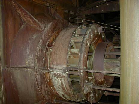
6 ESP Field Testing Field Testing Velocity Temperature Pressure Particulate Chemical species Video inspection 5


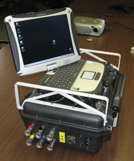
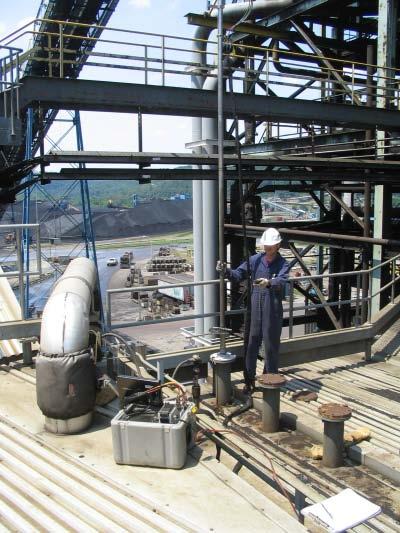

7 ESP Field Testing Field Testing 6


8 ESP Field Testing Field Testing Video probe in SCR reactor Video probe in pulverizer throat 7


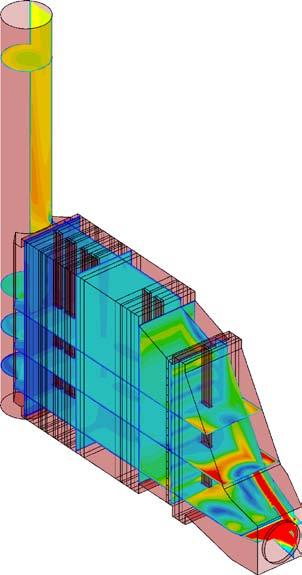
9 Computational Fluid Dynamics (CFD) Numerical simulation of flow Utilize high speed computers and sophisticated software Calculate flow properties Velocity Pressure Temperature Ammonia Particle streamlines 8


10 Computational Fluid Dynamics (CFD) Control Volume Approach Divide the flow domain into distinct control volumes Solve the Navier-Stokes equations (Conservation of Mass, Momentum, Energy) in each control volume Inflow Outflow Control Volume or Cell 9 ESP model with 3,550,000 cells


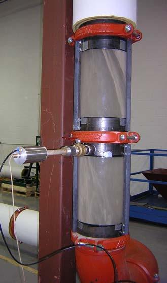
11 Physical Flow Modeling Lab representation of geometry Typical scale 1:8 to 1:16 Cold flow modeling Visualize flow with smoke Simulate ash deposition Measure flow properties Velocity Pressure Tracer gas 10

12 Typical 1/12 scale physical model Turning vanes Vanes Rectifier Catalyst layers AIG w/static mixers Economizer bypass Economizer outlet Air heater Dampers LPA screen 11

13 Outline Introduction Flow Distribution Analysis Techniques Application to Boilers Primary / Secondary Air Systems Furnace Application to APC Equipment Other Applications Conclusions Questions 12


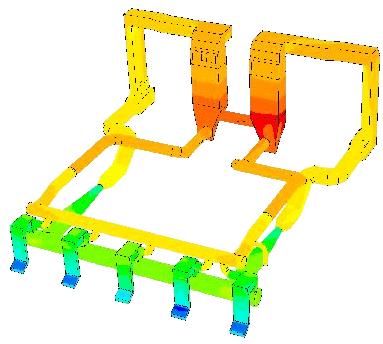


14 Primary Air / Coal Flow Balancing Optimize combustion Balance PA flows Equal coal flow per burner Adequate fineness Modeling and testing 13


")


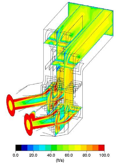
15 Windbox Flow Balancing Optimize combustion Balance secondary air Control flow entering burner (ram air effect) Modeling and testing Baseline Max deviation 29.4% Burner SA flow balance Design Max deviation 9.2% 14


16 Furnace Combustion Optimization Typical goals Reduce NOx Minimize LOI Improve heat transfer Avoid corrosion Decrease slagging 15

17 Outline 16 Introduction Flow Distribution Analysis Techniques Application to Boilers Application to APC Equipment ESP FF Mercury / SO 3 SCR FGD Other Applications Conclusions Questions


18 ESP Flow Optimization Flow distribution Flow balance between cells Pressure loss Thermal mixing Gas conditioning Ash deposition 17
19 ESP Velocity Distribution Uniform velocity within collection region Industry standards ICAC % RMS deviation 18

20 Gas Flow Balance Industry standard +/- 10% deviation 21 % 35 % 26 % 18 % 19 Percent of total mass flow through each chamber

21 ESP Temperature Stratification Upper ESPs AH exit Lower ESPs Piggyback ESPs 20

22 ESP Temperature Stratification 21
23 ESP Gas Conditioning Modify ash resistivity SO 3 Ammonia Others Resistivity 5 ppm SO 3 Temperature Low SO 3 Concentration High SO 3 Concentration 22 SO 3 Concentration

24 Ash Deposition Drop out Re-entrainment 23


25 Fabric Filter Flow Modeling Uniform velocity distribution and equal balance between compartments Compartments out-of-service Avoid bag erosion Ash deposition 24


26 Fabric Filter Flow Modeling 25 FF with SDA


27 Mercury / SO3 Reduction Injection upstream of baghouse or ESP Activated carbon Lime, Trona, SBS, etc. Uniform sorbent distribution Maximize residence time 26

 or popcorn ash capture Ash deposition")
28 SCR Flow Optimization Velocity distribution Thermal mixing NOx profile / mixing Ammonia injection Pressure loss Large particle ash (LPA) or popcorn ash capture Ash deposition 27


29 SCR Velocity Distribution Uniform velocity profile At ammonia injection grid At catalyst inlet At air heater inlet Minimal angularity At catalyst inlet 28


30 SCR Thermal Mixing SCR low load operation with economizer bypass CFD model to design mixer using full scale operating conditions Physical model tracer gas tests to confirm design 630 F 825 F 553 F Without mixer, ΔT = ±83 F With mixer, ΔT = ±15 F 29


31 SCR Ammonia Injection Desire uniform NH3-to-NOx ratio at catalyst Tracer gas used to represent flows in physical model Track gas species in CFD 30


32 SCR Large Particle Ash Capture Catalyst openings for coal-fired plants are smaller than LPA particles Once LPA becomes wedged into the catalyst, fine ash builds up as well Hard to clean Get dunes of ash on top layer catalyst 31


33 LPA System Design Key Points Capture LPA in hoppers of adequate size LPA screens have become standard practice Ash deflection baffles also useful Screen erosion and pluggage remain issues 32


34 Ash Deposition Duct floors Turning vanes Catalyst 33


35 Ash Deposition Model Testing Drop out Re-entrainment 34


36 Wet FGD Flow Modeling Flow distribution Water droplet behavior Pressure loss Solids deposition 35

37 Outline Introduction Flow Modeling Methods Application to Boilers Application to APC Equipment Other Applications Conclusions Questions 36


38 Power Industry 37 Fans Ducts Pulverizers Windboxes Furnaces Air Heaters Stacks Turbines Condensers HRSGs


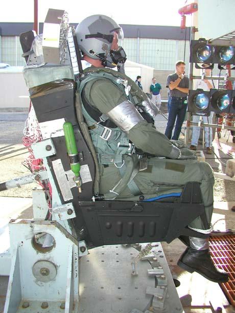


39 Aerospace Spacecraft Aircraft Missiles Engines Source: NASA 38


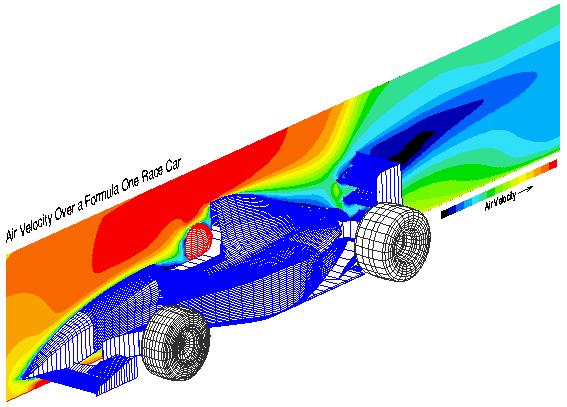


40 Vehicle Design Aerodynamics HVAC, cooling systems Engine components 39


41 Food Processing Baking Toasting Roasting Drying Frying Chilling Coating Mixing 40


42 Conclusions Gas flow patterns have significant impact on the performance of power plant equipment Analysis and design tools include field testing and flow modeling CFD and physical modeling are applied to a wide range of equipment from the fan to the stack 41

43 Questions? 42