Agenda. 1. Introduction. 2. History of Distillation. 3. Types of Stages. 4. Tray Fundamentals. 5. Tray Efficiencies
|
|
|
- Gwen Collins
- 5 years ago
- Views:
Transcription
1 Agenda 1. Introduction 2. History of Distillation 3. Types of Stages 4. Tray Fundamentals 5. Tray Efficiencies
2 Introduction Distillation Distillation is the separation of key components by the difference in their relative volatility, or boiling points. It can also be called fractional distillation or fractionation. For close boiling mixtures many stages are required to reach the desired purity.
3 Introduction Distillation is favored over other separation techniques such as crystallization or membranes when; 1. The relative volatility is greater than 1.2, 2. Products are thermally stable, 3. Large rates are desired, 4. No corrosion, precipitation or explosion issues are present.
4 Introduction α = 5 Y α = 1 α = 2 α = X
5 Introduction Distillation is the most common separation technique and is energy intensive. Distillation can consume more than 50% of a plant s operating energy cost.
6 Introduction A way to improve an existing plant s operating cost is to improve their efficiency and operations by process optimization and control. This cannot be achieved without first an understanding of distillation principles and design.
7 Introduction This introduction of Distillation is provided by which is a chemical engineering web site that publishes technical articles on distillation, process optimization, operations training, personal improvement, process unit safety and environmental concerns.
8 Introduction This introduction of Distillation is provided by provides specialized training courses in the areas of Petroleum Refining, Petrochemicals, Distillation, Operational Excellence, Safety, Chemical Engineering for Non Chemical Engineers, Petroleum Refining for Non Technical Professionals, Petrochemicals for Non Technical Professionals, Olefin and Aromatics Processes, and Project Management. Our courses can be held 'in house' or in regional seminars.
9 Distillation History Early Distillation was basically batch stills to produce ethanol. The Crude ethanol was placed in a still and heated, the vapor condensed for consumption. Later crude oil was placed in batch stills to produce lamp oil.

10 Distillation History

11 Distillation History
12 Distillation History The next progression was to continually feed the still and recover the light product. Notice the separation that can be accomplished in one stage.
13 Distillation History

14 Distillation History
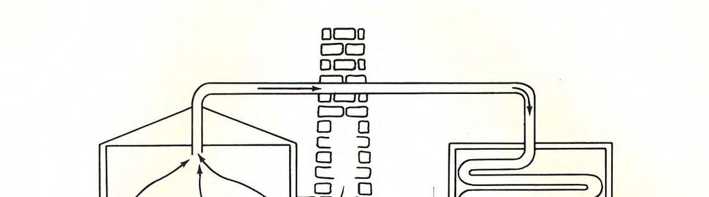
15 Distillation History The next progression was to place the stills in a column and interchange the vapor and liquid to improve recovery. To obtain good separation you need many stills in series.


16 Distillation History

17 Distillation History
18 Distillation History Early trays were dual flow trays, which then progressed to bubble cap trays and then down comers were added.
19 Distillation History Early small towers has one or two large bubble caps per tray. Early flow measurement was made by counting the strokes of a positive displacement pump.
20 Distillation History Early still men set their reflux rates in strokes per minute. All instrumentation was local. You ran the units by sound and feel.
21 Distillation History A Kerosene Hydrotreater built in 1952 had one bubble cap per tray on the Stripper Tower, which was one meter in diameter.
22 Distillation History 1 Bubble cap per Tray 1 m
23 Distillation History The liquid and vapor traveled through the center of the column and mixed on the outer ring of each bubble cap.
24 Distillation History Later when tray efficiency became more important, flow on the tray began to be studied and several types of trays with changed flow patterns were developed.
25 Types Of Distillation Columns 1. Batch Distillation 2. Continuous Distillation A. Multiple Feeds and Products B. Extractive Distillation C. Reactive Distillation
26 Types Of Distillation Columns There are many types of distillation columns; each designed to perform specific types of separations and each with different characteristics. Towers can be classified into two main classifications based on how they are operated. These two classes are Batch Distillation and Continuous Distillation.
27 Types Of Distillation Columns Batch Distillation, the feed to the column is introduced batch-wise. The column is charged with a 'batch' and then the distillation process is carried out. When the desired task is achieved, a next batch of feed is introduced.
28 Types Of Distillation Columns In contrast, Continuous Distillation processes a continuous feed stream. No interruptions occur unless there is a problem with the column or surrounding process units. They are capable of handling high throughputs and are the more common of the two types.
29 Types Of Distillation Columns Additional variations may be utilized in a Continuous Distillation Column. The column may have multiple feed points and products.
30 Types Of Distillation Columns The column may have a solvent added to the system to help increase the separation; this type of column is named an extractive distillation column. The column may have a catalyst bed and reaction occurring in the column; this type of column is named a reactive distillation column.
31 Types of Stages 1. Flash Drum 2. Reboiler / Condenser 3. Trays A. Dual Flow Tray /Ripple Tray B. Bubble Cap Tray C. Sieve Deck Tray D. Valve Tray E. Down comer Advances 4. Packing A. Random B. Structured
32 Types of Stages 1. Flash Drum The simplest type of distillation device is the flash drum. It is a single stage and can approach 100% of equilibrium limits it there is sufficient residence time.
33 Types of Stages 1. Flash Drum An over head receiver is an example of a flash drum. The separation of a single flash drum is limited. A 50:50 mixture of ethylene and propylene can only be separated to about 80:20 in a single flash drum.
34 Types of Stages Vapor Liquid
35 Types of Stages 2. Reboiler / Condenser A reboiler is a flash drum with heat exchange. It can approach 100% of equilibrium limits it there is sufficient residence time. The three normal types of reboilers are horizontal thermosyphon, vertical thermosyphon, and kettle drums. The best design is for the liquid from the bottom tray to pass through the reboiler at least once before being drawn off as tower bottoms.
36 Types of Stages 2. Reboiler / Condenser A Condensers is a flash drum with heat exchange There are three major types of condensers; total, partial, and hot vapor by-pass. Each has its best application.
37 Types of Stages A. Partial Condenser The partial condenser is best used when there is a large difference in the overhead vapor compositions. For example when there is a small amount of methane and hydrogen mixed in a propylene stream, like in the propylene towers. The partial condenser condenses the propylene and leaves the methane and hydrogen as a vapor to be vented from the overhead receiver.
38 Types of Stages A. Partial Condenser This type of condenser works well for most applications. The system needs to be reviewed to address the potential build of on non-condensable gases in the heat exchanger that can reduce the cooling potential of the exchanger.
39 Types of Stages A. Partial Condenser Vent
40 Types of Stages B. Total Condenser The total condenser is best used when there is a small difference in the overhead vapor compositions. The overhead vapors can be condensed at approximately the same temperature. This system also needs to be reviewed to address the potential build of non-condensable gases in the heat exchanger that can reduce the cooling potential of the exchanger.
41 Types of Stages B. Total Condenser Vent
42 Types of Stages C. Hot Vapor By Pass Condenser The hot vapor by pass condenser is best utilized when there is the potential for large changes of overhead vapor composition. The vapor by pass can be used to maintain the pressure in the tower system when the light components are lower than design. The hot vapor by pass condenser also has a lower installed cost due to the heat exchanger being installed on the ground level.
43 Types of Stages C. Hot Vapor By Pass Condenser The negatives of the Hot Vapor By Pass Condenser is that the by pass can be opened too much, increasing the temperature of the reflux. This reduces the tray efficiency in the top of the tower, and raises the tower pressure, which makes hydrocarbons harder to separate. This system, because of the physical location of the exchanger, has even higher potential to build non-condensable gases in the heat exchanger that can reduce the cooling potential of the exchanger.
44 Types of Stages C. Hot Vapor By Pass Condenser Vent
45 Types of Stages 3. Trays A. Baffle Trays B. Dual Flow Tray /Ripple Tray C. Bubble Cap Tray D. Sieve Deck Tray E. Valve Tray F. Tray advances
46 Types of Stages 3. Tray design Trayed Columns utilize a pressure and temperature differential to separate the products. For most trayed columns, the weir holds a liquid level of each tray. The vapor must over come this liquid head to move up the column. On the tray the vapor and liquid are contacted and then above the tray they are separated.
47 Types of Stages 3. Tray design Any deviation that develops that restricts the vapor and liquid from contacting and then separating will deteriorate the column s ability to meet design specifications. Trays utilize the staged contact principle to separate products.
48 Types of Stages 3. Tray design One of the first trays developed was the dual flow tray. The liquid and vapor traveled up and down the column in the same tray opening. Tray design then moved to sieve decks, to bubble caps, valve trays, and to directional flow valve trays. For trays to function they need to mix the vapor and the liquid, then separate the vapor and the liquid. Each function must be as complete as possible.
49 Staged Equipment: the mechanism Vapor and liquid mixes to form a froth. Mass transfer occurs within the froth. The froth overflows across a weir. The vapor disengages and move to the tray above. The bulk liquid flows down the downcomer to the next tray. The steps are repeated in the next tray.
50 Types of Stages A. Baffle Trays Baffle trays are trays of low fouling potential, with low efficiency. They have open areas approaching 50% where a high efficiency tray will have an open area of less than 15%. Three major types of baffle trays are 1. Shed Decks 2. Side to Side Trays 3. Disk and Donut
51 Types of Stages 1. Shed Decks Shed decks are essentially angle iron beams of various sizes from two to ten inches that are placed in rows across the column. They typically are at on 24 inch tray spacing. They may be set in overlapping rows or rotated 90 degrees from tray to tray.
52 Types of Stages Shed Trays
53 Types of Stages 2. Disk and donut trays Disk and donut trays are slightly sloped trays that allow the liquid to splash from inner circle ring to outer circle ring. Fouling potential of this tray is low along with the efficiency.
54 Types of Stages Disk and Donut Trays
55 Types of Stages 3. Side to side trays Side-to-side trays are trays that allow the liquid to splash from side to side. The decks can be sloped. Fouling potential of this tray is low, as with efficiency

56 Types of Stages Side to Side Trays Liquid Liquid Vapor Vapor Side-to-Side Trays
57 Types of Stages B. Dual Flow Tray /Ripple Tray Because dual flow trays do not have weirs the vapor rate is what maintains the level on the trays. It is very important in the operation of dual flow trays to keep the reflux and reboiler rates very stable to maintain a constant level on the tray deck.
58 Types of Stages B. Dual Flow Tray /Ripple Tray These openings can vary in size from very small (1/8 ) to large (1 ) diameter openings. Smaller holes have been found experimentally to obtain higher tray capacity for exactly the same open area. However, smaller holes have the potential to plug up in fouling service. Typical perforation sizes are 1/4 to 1/2 for most applications.
59 Types of Stages B. Dual Flow Tray /Ripple Tray The challenge of dual flow trays is mal-distribution, the vapor traveling up one side of the column and the liquid down the opposite side. In a windstorm the top of a column can move as much as 6 inches (150 MM), and build a hydraulic instability within the column, which a dual flow tray cannot correct within itself.
60 Types of Stages C. Bubble Cap Tray A bubble cap tray has a riser or chimney fitted over each hole, and a cap that covers the riser. The cap is mounted so that there is a space between the riser and the cap to allow the passage of vapor. This vapor rises through the chimney and is directed downward by the cap, finally discharging through the slots in the cap, and bubbling through the liquid on the tray.
61 Types of Stages
62 Types of Stages D. Sieve Deck Tray A sieve tray is essentially a plate with holes punched into the plate. The number and size of the holes is based on the vapor flow up the tower. The liquid flow is transported down the tower by down comers, a dam and overflow device on the side of the plate, which maintains a set liquid level on the tray.
63 Types of Stages D. Sieve Deck Tray To maintain the liquid level on the tray a minimum amount of vapor traffic up the tower must be maintained, or the liquid level on the tray will weep down to the next tray through the holes punched on the plate. Typically sieve deck trays have a minimum capacity, or downturn, of approximately 70%.
64 Types of Stages E. Valve Tray One of the next developments was to add a variable valve opening to the tray deck. This valve would open in relation to the vapor flow. The advantage to this design was the ability to maintain the liquid level on the tray deck. Typically valve deck trays have a minimum capacity, or downturn, of approximately 60%.
65 Types of Stages Tray Advancements The latest in tray advancements involve the flow across the tray and the down comer design.
66 Design of Trays to Improve Efficiencies and Capacities Items that lead to improvements in efficiency include; 1. Path flow length 2. Deck opening size 3. Elimination of stagnant zones 4. Down comer outlet devices / froth promoters 5. Weir Heights 6. Hydraulic Rates
67 Design of Trays to Improve Efficiencies and Capacities Path Flow Length For a conventional tray recommendation would be maintain above 500 mm. For a multiple downcomer recommendation would be to maintain above 300 mm Swept back weirs that are utilized for more capacity, has the added advantage that they increases the path flow length. This is one of the few cases where one can see both capacity and efficiency increases at the same times. Normally there is a trade off between capacity and efficiency.
68 Design of Trays to Improve Efficiencies and Capacities Opening Size There is an optimum bubble size, therefore an optimum opening size. Too small or too large can effect the size of the bubble, leading to loss of efficiency. Here is the normal trade off between capacity and efficiency.
69 Design of Trays to Improve Efficiencies and Capacities Elimination of stagnant zones parallel flow across a cordial surface can lead to stagnant areas. Liquid directional valves can help eliminated the stagnant zones.
70 Design of Trays to Improve Efficiencies and Capacities Concept The devices force the liquid on the tray to go in directions it does not naturally wish to flow. By strategically designing and placing the devices on the tray deck, plug flow of liquid is achieved and stagnation eliminated.
71 Design of Trays to Improve Efficiencies and Capacities Down comer outlet devices / froth promoters the clear liquid exiting the down comer becomes a froth on the tray. Items that assist this froth generation improve efficiency. A small inlet weir will help efficiency, but should not be utilized in fouling service.


72 Design of Trays to Improve Efficiencies and Capacities Here is a picture of an air / water tray test device. At low vapor flow, the clear liquid is shown.
73 Design of Trays to Improve Efficiencies and Capacities Weir Heights - The weir height has an effect on the tray efficiency. Recommendations are not to exceed 100 mm or 1/6 of tray spacing, and 50 to 75 is suggested for all services except vacuum services. Point Efficiency (%) Liquid Height (mm)
74 Types of Stages
75 Design of Trays to Improve Efficiencies and Capacities Hydraulic Rates - The hydraulic rate has an effect on the tray efficiency. At low rate trays will weep, at high rates froth touches the next tray. When the V:L ratios are not equal molar, efficiency will decrease.
76 Types of Stages 4. Packing Random and Structured Packed Columns generate a mass transfer area by providing a large surface area over which the liquid can transfer heat and mass to the vapor. Packing utilizes a continuous contacting principle to separate products. A major advantage to packed columns is the reduction in pressure across the column.
77 Types of Stages 4. Packing Typically the column pressure drop for a packed column is less than that of a trayed column because of the percent open area. Typical percent open area of a trayed column is 8 to 15%, whereas a packed column can approach 50%. Liquid accumulation for a packed column is lower than that of a trayed column.
78 Types of Stages 4. Packing Another advantage of packed column is reduced foaming. Packing generates thin films instead of fine droplets for mass and heat transfer, reducing entrainment when foaming agents are present. Packing has been used successfully in low-pressure distillation applications, less than 150 psig.

79 Types of Stages A. Random Packing

80 Types of Stages B. Grid Packing


81 Types of Stages C. Structured Packing
82 Non-staged Equipment: the mechanism Bulk liquid is broken into fine droplets when in contact with packings. Provides large surface area for effective heat and mass transfer. Appears as a continuous froth across the height of the packed bed.
83 Non-staged Equipment: the mechanism The introduction of vapor and liquid to the packing is very important. Trays will normally eventually equalize whatever mal-distribution is developed by the vapor and liquid feeds. Packing will enhance whatever mal-distribution is developed by the introduction of the vapor and liquid feeds.
84 Non-staged Equipment: Micro phenomena A distributor showers down liquid at different locations on the packed bed. The liquid needs to travel some distance before meeting and remixes into a froth. A layer of dead zone exist on top of bed. Challenge is greater if 2 or more liquid phases exist.
85 Concepts 1. Up till this point we have discussed hardware. 2. Now let us discussed why the hardware might work. 3. In distillation the hardware was developed and then a study was conducted to understand why it might work.
86 Concepts 1. Hydrocarbons separate better at lower pressure. The nature of hydrocarbons is such that they separate better at lower pressure. Normally the pressure of a tower is set as low as possible based on the ability of the over head condenser to condense the over head vapor. The preferred cooling medium is water and the tower pressure is raised until the over head vapor can be condensed at 90 degrees F / 45 degrees C.
87 Concepts 1. Hydrocarbons separate better at lower pressure. A balance must be done between the construction cost and the utility cost. The ability to separate determines the number of trays, which is a construction cost. To utilize lower pressure can require refrigeration, which is a utility cost. Low pressure DeMethanizers with Methane Refrigeration can be shown to be cost effective. Some C2 Splitters run at lower pressure than other designs utilizing this lower pressure separation ability.
88 Concepts 2. Heat is a form of energy caused by the motion of molecules. Heat is a form of energy. The motion of molecules causes heat energy. When energy is added to a substance, the motion of the molecules increases. When energy is added to a substance and the temperature of the substance increases, this is called sensible heat. When energy is added to a substance and the substance changes phases from a liquid to a gas, that energy is called latent heat.
89 Concepts 2. Heat is a form of energy caused by the motion of molecules. The unit of measurement of energy is called a calorie. It is the amount of energy to raise one gram of water, 1 degree C. To raise 1kg of water 1 degree requires 1000 calories. To change the phase of water from liquid to a gas requires 537 calories, which is about 500 times the sensible heat value. To change the phase of ethylene from liquid to a gas requires 114 calories.
90 Concepts 2. Heat is a form of energy caused by the motion of molecules. The availability and large latent heat value are the reasons we use water as a heat carrier. The large latent heat value can be utilized in reboilers. Because we do not use the latent heat in pumps and compressors, the temperature and pressure change are the energy carriers.
91 Concepts 6. Equilibrium is the state which systems will establish, if given enough time. A vessel filled with two hydrocarbons is said to be at equilibrium if the number of light molecules escaping from the liquid is equal to the number returning to the liquid. In one vessel because of the transfer of molecules from the liquid to the vapor, total separation of two similar hydrocarbons cannot be obtained.
92 Concepts Hydro Carbon Formula Molecular Weight Boiling Point (F) Density (ft 3 /lb) Flammability Limits Low/High Hydrogen H / 4.00 Methane CH / 15.0 Ethylene C 2 H / 36.0 Ethane C 2 H / 13.0 Propylene C 3 H / 11.7 Propane C 3 H / 9.5 Iso Butane C 4 H / 8.5
93 Tower Balances A. Mass Balance B. Energy Balance C Composition Balance
94 Mass Balance All vessels will eventually reach a material balance, mass in equals mass out. For distillation towers the material balance is; Mass In = Mass Out + Accumulation
95 Mass Balance Sources of material into the tower normally are the feed points. Sources of material out of the tower include Overhead Vapor, Overhead Liquid, Side Draws and Tower Bottoms flows.
96 Mass Balance Sources of accumulation include Overhead Receiver or Reflux Drum, Tower Bottoms Reservoir, and level of hydrocarbons on the trays. Two of the accumulations are straight forward; the Overhead Receiver and the Bottoms Reservoir.
97 Mass Balance The third accumulation, the level on the trays, is much more difficult to quantify. It is by far the largest accumulation in the tower. To build the inventory in the C2 Splitter Tower takes 8 hours, but less than one hour for the over head receiver to be filled.
98 Mass Balance The tower delta P is a guide to how much level is on the trays. The tower delta P is based on the amount of reflux that is added to the tower. The reflux is made in the reboiler, therefore the level on the trays is determined by reboiler. A stable reboiler heat input will stabilize the tower.
99 Mass Balance One of the first tower control schemes was the Material Balance that was developed in 1930s. A field operator looking at sight glasses controlled the overhead and bottoms levels.
100 Mass Balance Today with level controls, the Material Balance Control Scheme can be utilized if the product specifications are lax. The Material Balance Control Scheme does not address the accumulation of level on the trays, the tower energy, and composition balance.
101 Mass Balance For most high purity product this is not the best control scheme due to the large number of trays in product fractionators.
102 Mass Balance PI TI
103 Energy Balance All vessels will eventually reach an energy balance, energy in equals energy out. For distillation towers the energy balance is; Energy In = Energy Out + Accumulation The main source of energy into the tower normally is the reboiler. The feed can also be a source of energy if it is preheated.
104 Energy Balance The main sources of energy out of the tower are the Overhead Condenser and the Tower Bottoms Flow. Smaller sources include Overhead Vapor, Overhead Liquid, Side Draws and Tower Feed if it is cooled. Sources of accumulation include, Tower Bottoms Reservoir, and level of hydrocarbons on the trays. Two of the accumulations are straightforward; the Overhead Receiver and the Bottoms Reservoir.
105 Energy Balance The third accumulation, the level on the trays, is much more difficult to quantify. It is by far the largest energy accumulation in the tower. Three things happen on a tray when a reflux move is made. The first is the level on the tray changes.
106 Energy Balance The second is the energy or temperature on the tray changes. The third is that the composition on the tray changes. If each of these changes takes one minute and there are 30 trays in the column, it takes one hour and thirty minutes for the change to be seen at the tower bottoms.
107 Energy Balance If there are 100 trays in the column like in the C2 Splitter, it takes five hours for the change to be seen in the tower bottoms. If there are 250 trays like in a Polymer Grade C3 Splitter, it takes 12 hours and thirty minutes for the change to be seen in the tower bottoms.
108 Energy Balance The Energy Balance Control Scheme was developed in 1960s. Instrumentation was improving and flow meters were becoming more accurate. A current orifice plate flow meter can approach 1.0% accuracy, if they are installed correctly and calibrated.
109 Energy Balance An average field orifice plate flow meter is normally considered to have 2.5% accuracy. The latest flow meters, which uses the vibrations of a tube as the fluid flows by can approach 0.01% accuracy.
110 Energy Balance Because of the improved instrumentation, the heat input to the tower could be measured and controlled. This led to the Tower Energy Balance Control Scheme. The energy to the reboiler was measured and used as a control point. The energy was removed in the overhead condenser.
111 Energy Balance The overhead product was sampled and the product was changed by the sample results. The sample results were returned typically four to five hours after the samples were caught. This meant that the tower adjustments were always behind what the tower actual operation was. To compensate for this lag time the products were always kept above the specification to ensure on test product.
112 Energy Balance To be consistently above the sell specification gives away product, reducing your cash margin. The main problem with the energy balance control scheme is that is does not take into account the composition balance.
113 Energy Balance PI
114 Energy Balance A later variation of the energy balance control scheme was the Delta T Energy Balance. At constant pressure the temperature can be an indication of the composition and the product flow can be controlled by the difference in the two temperature points.
115 Energy Balance For example in a Benzene Toluene Splitter the lower temperature point will began to increase as the toluene concentration increases. This will reduce the delta T between the temperature points. The product flow can then be decreased, which will increase the reflux to the tower, resulting in the toluene composition being decreased at the Benzene Product.
116 Energy Balance The advantage of a delta T over a single point is that the delta T takes the pressure deviations out of the control scheme. This control scheme works, but ignores the composition balance.
117 Energy Balance PI TI DT TI
118 Energy Balance A third variation of the Energy Balance Control Scheme is the Ratio Energy Balance. This is the design of 1980s ethylene plants. It works, minimizes reflux, but ignores the composition balance.
119 Energy Balance PI TI DT TI
120 Composition Balance All vessels will eventually reach a composition balance, composition in equals composition out. For distillation towers the composition balance is; Composition In = Composition Out + Accumulation
121 Composition Balance For the Propylene Tower a propylene balance can be developed. The propylene in the feed must equal the propylene that leaves the tower plus the accumulation of propylene in the tower. Sources of accumulation include, Tower Bottoms Reservoir, Overhead Receiver and level of hydrocarbons on the trays.
122 Composition Balance Two of the accumulations are straightforward; the Overhead Receiver and the Bottoms Reservoir. The third accumulation, the level on the trays, is much more difficult to quantify. It is again the largest accumulation in the tower.
123 Composition Balance In the 1970s analyzers were becoming reliable and control schemes that utilized them became common. A composition balance could be maintained by utilizing the mass flows and the analyzer results leading to better distillation control. Present Stone and Webster recommendations are the composition balance control scheme.
124 Composition Balance The tower feed and composition are analyzed and used as a feed forward control for the product. The product rate and composition are analyzed and used as a feed back control. The sum of these two is used to balance the tower considering all three balances.
125 Composition Balance PI AI AI
126 Tower Problem Solving 1. Foaming 2. Entrainment 3. Weeping / Dumping 4. Flooding
127 Tower Problem Solving Do simple checks first. 1. Ensure that levels are accurate. 2. Calculate column pressure drop and then measure pressure drop. 3. Survey column temperature profile. Review survey temperature reading to operation s readings.
128 Tower Problem Solving Verify Tower Operations. 1. Sample Feeds and Products. 2. Calculate mass balance to within 2% accuracy, if not calibrate flow meters. 3. Survey heating and cooling temperatures. 4. Have engineers simulate these results. If no problems are identified consider scanning the column.
129 Tower Problem Solving In distillation towers there are actually two accumulators. The first is normally obvious, the over head receiver, the second is the bottom section of the tower. These accumulators are used to stabilize the operation of the tower and down stream operations. This internal surge drum creates an inventory to act as a buffer.
130 Tower Problem Solving If this internal level is allowed to rise above the reboiler return, stripping inlet, or feed inlet, flooding can occur. There is an inherent error built into sight glass and level instrumentation. The sight glass and level instrumentation contain non aerated liquid, called clear liquid, which is not a true indication of the condition of the liquid within the tower.
131 Tower Problem Solving The liquid within the tower will have two levels, a clear liquid level below the aerated liquid level. Because the aerated level will have lower specific gravity than the clear liquid within the instrumentation, the tower level will be higher than the instrumentation indicates. If the level in the tower is higher than the feed or reboiler return, entrained liquid can be carried to the next stage causing flooding.
132 Tower Incidents Attached is a list of tower incidents that was found in the literature from HZ Kister Recent Trends in Distillation Tower Malfunctions 1. Fouling, plugging and Coking issues 2. Tower Bottoms and Reboiler Return issues 3. Packing Liquid Distributors issue 4. Intermediate Draws 5. Assembly Mishaps
133 Tower Incidents 1. Fouling, plugging and Coking issues A. Coking B. Precipitation - salts C. Scale, corrosion products D. Solids in feeds
134 Tower Incidents 1. Fouling, plugging and Coking issues location A. Packing beds and Distributors B. Trays, active areas and down comers C. Draw lines D. Instrument lines E. Feed lines
135 Tower Incidents 2. Tower Bottoms and Reboiler Return issues A. High liquid levels B. Impingement by vapor inlets C. Vapor Mal-distribution D. Water induced pressure surges E. Leaking reboiler draw F. Gas entrainment in liquid bottoms
136 Tower Incidents 3. Packing Liquid Distributors issues A. Distributor Overflow B. Plugging C. Fabrication mishaps D. Feed entry problems E. Damage F. Poor hole pattern G. Poor irrigation quality
137 Tower Incidents 4. Intermediate Draws A. Leakage at draw B. Restriction of vapor - choking of draw line C. Plugging
138 Tower Incidents 5. Assembly Mishaps A. Packing Liquid Distributors B. Packing assembly C. Tray Panels D. Internal mis-orientation at feeds and draws
139 Conclusions Distillation is one of the major unit operations in processing plants. It is energy intensive and has opportunities to be optimized. Product recovery and purity can be improved by understanding the principles of distillation. These principles need to be understood in advance of operating and trouble shooting a distillation column for the operator or problem solving to be effective.
140 Introduction This introduction of Distillation is provided by Kolmetz.Com is a chemical engineering web site that publishes technical articles on distillation, process optimization, operations training, personal improvement, process unit safety and environmental concerns.
141 Introduction This introduction of Distillation is provided by provides specialized training courses in the areas of Petroleum Refining, Petrochemicals, Distillation, Operational Excellence, Safety, Chemical Engineering for Non Chemical Engineers, Petroleum Refining for Non Technical Professionals, Petrochemicals for Non Technical Professionals, Olefin and Aromatics Processes, and Project Management. Our courses can be held 'in house' or in regional seminars.