Consilium Marine & Safety AB. Workshop Water Ballast Management Tutto pronto per l entrata in vigore? Facoltà di Ingegneria di Genova 17 Maggio 2012
|
|
|
- Flora Payne
- 5 years ago
- Views:
Transcription


1 Workshop Water Ballast Management Tutto pronto per l entrata in vigore? Facoltà di Ingegneria di Genova 17 Maggio 2012
2 About OceanSaver AS Norwegian based company Founded 2003 Headquarter in Drammen, 40 km from Oslo, Norway Mission: To Develop, Manufacture and Deliver World Leading IMO Compliant Systems for Ballast Water Management Vision: Creating today her tomorrow Ballast water treatment is our sole focus Employees background from marine / offshore industry Leading supplier for larger vessels with unique know-how and competence

3 Target market segments Crude Oil Tankers Chemical Tankers LNG Carriers Bulk Carriers VLCC Suezmax Aframax Ballast pumps from 2 x 750m3/h Ballast pumps from 2 x 2.000m3/h Ballast pumps from 2 x 750m3/h


4 OceanSaver main locations Head Office in Drammen Seaside laboratory in the Oslo fjord Filter test facility Gdansk Poland

5 Worldwide Network Canada & USA: American United Marine Germany: Netherlands: MOE Marship Italy: Consilium Greece: Turkey: GEPA Alpha Marine China: Dan Marine Japan: Korea: Sumitomo & Shinsei Il-Jin Maritas India: Consilium Singapore: TMS
6 OceanSaver compliance IMO Type Approval by DNV / The Norwegian Maritime Directorate Class Approval by DNV Compliant for gas hazardous areas (Pump room & Deck installation) According to IMO PSPC intentions By paint manufacturers By DNV Safe gas handling (DNV approved)
7 Order references Vessel type BWTS Capacity Orders VLCC - MkI 2 x m3/h Ex 8 Korea (HHI & DSME) VLCC - MkI 2 x m3/h Ex 12 China (DSIC & SWS) VLCC - MkII 2 x m3/h Ex 2 China (RSHI) Suezmax - MkI 2 x m3/h Ex 2 Korea (HHI) Suezmax - MkII 2 x m3/h Ex 2 China (Bohai) 35 DWT Bulker MkII 2 x 800 m3/h 4 Korea (SPP) Chemical tanker - MkII 2 x 750 m3/h Ex sub 2 Korea (HMD) 162K LNG/C MkII 2 x 2.700m3/h 2 Korea (HHI) 72 DWT Bulker - MkII 1 x 1.200m3/h 4 Japan (Oshima) Car Carrier (PCTC) MkI 2 x 600 m3/h 1 Rerofit system installed & DNV approved PCTC / LNG/C open contract - MkII 2 x 600 m3/h or 2 x m3/h 9 retrofit systems (Norwegian owner) Total 48 systems Commissioned 9 systems
8 OceanSaver Mark II BWTS
9 MarkIIII achievements: Achievements Mark New System Additional ballast pump pressure bar Old System 3.5 bar Total power consumption (BWT system + ballast pumps) Reduced by % compared to old system Installation complexity Significantly reduced as number of components are decreased Total investment cost ( BWT system + yard installation cost) Certification Reduced by 50% due to reduced number of components and simplified installation IMO Type Approval Norway/DNV, Ex proof (DNV), PSPC compliant


10 Why filtration? Reduction of organic matter present in ballastwater > 50 micron = Zooplankton micron = Phytoplankton Reduction of sedimentation in ballast tanks With efficient filtration, the disinfection phase may be optimized Decreased amount of disinfectant required Filtration gives you control of the organic load and increase port state compliance


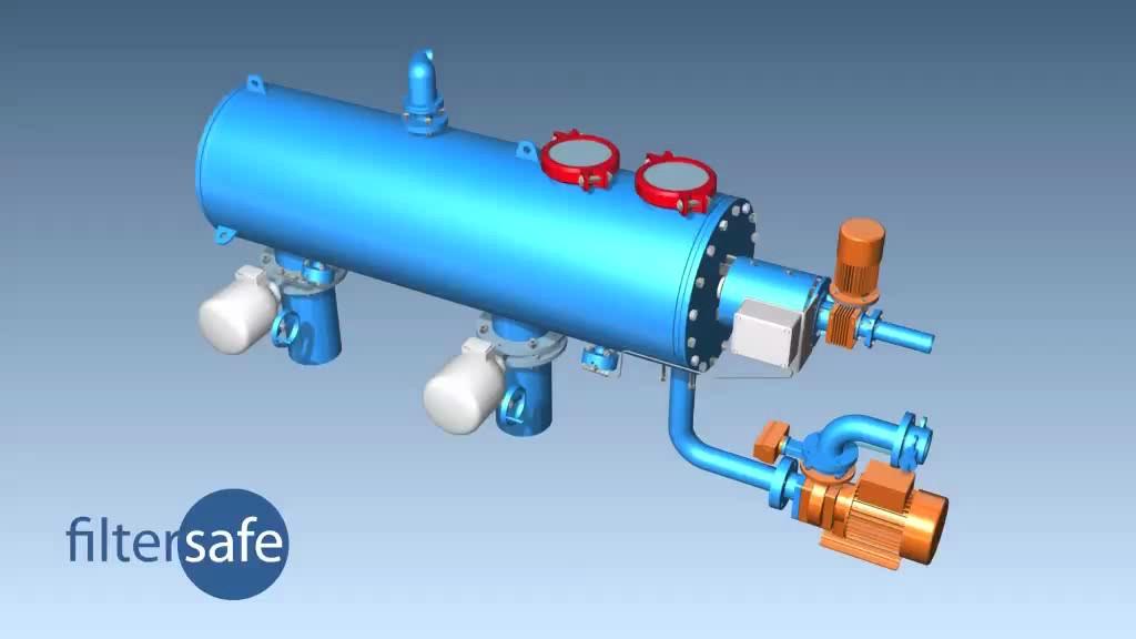
11 Filtration technology Ballast water is pumped onboard by the ballast pumps and filtered by a mechanical, fully automatic back-flushing filter. The filter is an automatic self cleaning filter equipped with a 40 micrometer screen. The filter will remove 99,5 % of the organic load above 40 micrometer. The filter is used at uptake and will when in use, automatically backflush all organic material back to the same water as where it has taken up by the ballast pumps. The filter is electrically or hydraulic driven.
12

13 Disinfectant technology (C2E Unit) C2E Disinfectant skid m3/h BWTS
14 Disinfectant OceanSaver patented Membrane Cell Technology An anolyte produced in the membrane cell is injected into the ballast water, oxidizing organic matter present in the ballast water The oxidants have a very short half time, and are consumed rapidly during the process of eliminating unwanted species The TRO level is reduced from 2.5 mg/l to 0.2 mg/l (discharge limit set out by IMO) within a few hours, making neutralization a contingency

15 Disinfection (C2E unit) Oxidant produced onboard without consumables Patented membrane cell technology Extremely efficient maximum level 2.5 ppm Rapid decay of TRO level half time 30 mins Generated oxidant: Hypobromeous species Dosage level self-adjusted by TRO sensors
16 De-ballasting Gravity discharge
17 Automation & Monitoring

18 C2E C2E HEATER C2E FEED PUMP DISINFECTANT TO FILTER A.P. TANK BALLAST PUMP FROM SEACHEST SUCTION FROM SEA CHEST TRO SENSOR TRO-N

19 Principle layout Bulk Carrier / LNG Carrier

20 Principle layout Crude Oil Tanker
21 OPEX 2 x Timeline Mark m3/h II Based on: Normal SW conditions BWTS power requirement 140 Kw Ballast pump additional power requirement 40 Kw each OPEX cost ballast system + ballast pump = USD/m3 El-power production cost USD / Kw.
22 Footprint, Power 2 x m3/h Footprint: Filter: 1.2 m2 Disinfectant unit: 6.4 m2 Total: 13 m2, remotely installed in engine room Power requirement:, during ballast intake only BWTS, design: 250 Kw BWTS, normal operation: 140 Kw

23 Corrosion assessment Mark II Initiated January 2011, following up the extensive 3rd party corrosion testing carried out for the Mark I system Uncoated coupons / marine epoxy coated coupons In cooperation with DNV Duration: 6 and 12months; Based on PSPC Crossover test (2 week ballast/ 1 week empty)
24 Option: N2 super saturation Reduced corrosion and oxidation of ballast tank coating The Nitrogen super saturation reduces Oxygen level in the ballast water from typically 7-8% to less than 2% This leads to reduced creep corrosion on exposed steel, and extended lifetime of the ballast tank coatings During the shipboard test carried out over 12 months and land based test carried out over 6 months, a reduction of anodes of up to 15% was measured The N2 option consists of an air compressor, N2 generator and a gas mixing unit, all of which are fully integrated into the OS BWTS automation system
25 BWT SYSTEMS FOR LARGE VESSELS COT > DWT LNG Carrier BULKERS > DWT


26 A lot of challenges are lurking below the surface! BWTS Capacity Type Approval Power consumption Need for neutralizer? Pressure drop Technology limitations Operational costs Class Approval Ex approval Corrosion challenges Space requirements Shipyard agenda
27 CHALLENGES OF INSTALLING BWT SYSTEMS ON LARGE VESSELS AT DIFFERENT STAGES Sales / Quotation ü Space for equipment and piping ü Power available on board Design / Preparations ü Surveys ü Documentation & Prefabrication ü MSB modifications & Sub-centrals Installation

28 PRINCIPLE LAYOUT TANKER WITH PUMP ROOM Separate system for AP Tank Common equipment Filters in Pump Room

29 Consilium Marine & Safety AB SALES / QUOTATION ü Space for equipment and piping GA BWT preliminary plan Vessels with pump room need remote location of equipment Location of equipment determined by available space AND piping/cable lengths Skid mounted BWT 10m x 10m for VLCC In a new deckhouse Component mounted BWT 40m2 for VLCC Local and remote location Others
30 Consilium Marine & Safety AB SALES / QUOTATION ü Power available on board ELEC. POWER LOAD ANALYSIS To be done before BWT selection All generators to be in operation BWT system should adjust power consumption acc. to water quality. SUEZMA SUEZMA BWT POWER VESSEL VLCC COT X X CONSUMPTION 75% BALLAST PUMPS 2 x x x x 1800 GENARATORS IN USE GEN. CAPACITY 1050 kwload FACTOR WITH BWT % CONSUMPTION 50% GENARATORS IN GENARATORS IN USE USE LOAD FACTOR 83% LOAD FACTOR WITH BWT BWT POWER BWT POWER 450 CONSUMPTION 25% CONSUMPTION GENARATORS IN USE GENARATORS IN 3 USELOAD FACTOR WITH BWT LOAD FACTOR 70% WITH BWT % 51% NO. OF SET TOTAL LOAD 1750 BWT POWER 3 COT 176 VLCC x x % % % 86% ,5 117, % 76% 84% 84% 63% 71% 64% % 54% 66% 78% 87% 75% 80% 61% 89% 71% %


31 Consilium Marine/ &PREPARATION Safety AB DESIGN ü Surveys, Documentation & Prefabrication LOCATION OF BWT COMPONENTS IN PUMP ROOM Very limited space Conventional measurements may not be sufficient Need for as built drawings 3D scanning

32 Consilium Marine/ &PREPARATIONS Safety AB DESIGN ü Surveys, Documentation & Prefabrication LOCATION OF BWT COMPONENTS IN PUMP ROOM

33 DESIGN / PREPARATIONS ü Surveys, Documentation & Prefabrication LOCATION OF BWT COMPONENTS IN PUMP ROOM
34 DESIGN / PREPARATIONS ü Main Switch Board modifications & Sub-Centrals VLCC 500kW for BWT 1250 A Fuses for 500kW BWT system Space in Main Switchboard MSB challenge to extend space in ECR

35 INSTALLATION ü Handling of heavy equipment ü Pipes max 70% prefabrication VLCC 30% of piping has to be done on board 8 tons of piping Connections to equipment and interfaces with existing piping will require high quality of prefabrication and time consuming on-site adjustments.
36 Electrical installation (cables) Substantial amount of additional cables for VLCC > 3km Power cables for main treatment units 3 x (1 x 3 x 95mm2) Some of BWT components can t be located near to MSBD Cable mm2 km 2 x 1,5 1,15 2 x 2,5 0,08 2 x 25 0,03 3 x 1,5 0,04 3 x 2,5 0,07 3 x 25 0,05 3 x 95 0,15 2 x 2 x 0,75 1,2 4 x 2 x 0,75 0,05 10 x 2 x 0,75 0,12 24 x 2 x 0,78 0,1 = 3,1


37 INSTALLATION ü Handling of heavy equipment, ü Pipes, max 70% prefabrication ü Long cables Heights between decks in Pump Rooms proper scaffolding Correct planning of lifting eyes for future service and maintenance Adding a single valve DN600 or sensors after prefabrication can be challenging