Proposal: Mechanical System Redesign
|
|
|
- Anis Jefferson
- 5 years ago
- Views:
Transcription

1 Proposal: Mechanical System Redesign The 959 Eighth Avenue Faculty Advisor: Dr. James Freihaut December 12, 2005
2 Table of Contents 1.0 Executive Summary Proposal Obectives 4.0 Preliminary Design Considerations 5.0 Proposed Mechanical System Redesign 6.0 Breadth Topics 7.0 Project Methods 8.0 Preliminary Research 9.0 References 10.0 Tentative Schedule

3 1.0 Executive Summary The thesis proposal serves as a guide for research to be conducted throughout the Spring 2006 semester. This research then culminates into a redesign of the mechanical system for the located in New York City. In addition to the mechanical redesign, other systems affected by the new design are also addressed through two breadth area studies. The attached proposal not only explains the principle redesign topic, but addresses justification, methodology, coordination, and integration issues. Before deciding upon a final redesigned system, several other alternative systems were researched. Ultimately the proposal will outline the use of a steam driven absorption cooling process with a dedicated outdoor air system paralleled by variable air volume distribution. Since the proposed redesign directly affects the electrical and structural system of the tower, these two areas will serve as the topics of the breadth analysis. A life cyle and annual operating cost analysis will also be conducted when redesign is completed. All research conducted will result in a presentation to The Pennsylvania State University Architectural Engineering Faculty in April 2006.
4 2.0 The Located in the Columbus Circle neighborhood of Midtown Manhattan, the new Hearst Tower rises from the center of the original landmark headquarters, built in The newly constructed tower will house corporate offices for the several magazines Hearst Corporation publishes, a cafeteria, auditorium, Good Housekeeping test kitchens, and assembly areas for corporate functions. In its entirety, the tower clams 42 stories totaling 856,000 square feet. With complete coordination among the buildings owners and engineers, the has become one of New York City s first Leadership in Energy and Environmental (LEED) Gold Certified high-rises. The initial decision to preserve the original landmark facade allowed approximately 85% of the original structure to be included into the new tower design. With its diagrid design, the tower also provided opportunities for structural savings. The diagonal grid design eliminates the need for horizontal beams and resulted in a savings of about 2,000 tons of steel. In addition to architectural and structural ingenuities, the buildings mechanical system also helped score LEED points. Airside System The current airside system of the is a central variable air volume (VAV), low temperature system. By providing low temperature supply air, 46F, the mechanical designers were able to downsize the mechanical shafts by 25%. Fan powered terminal units provide the supply air to each space and contain the fan and motor assembly, heating coil, and VAV damper. There are four large (110,00 CFM) air-handling units located on the 28 th floor, four smaller air handling units in the basement, and dedicated units serving the auditorium and kitchen area. The air-handling units operate such that 100% outdoor air is being delivered during 50% of the occupied hours, 50% outdoor air during 22% of the occupied hours, and minimum outdoor air, as required, during the remaining time period. Fifty-one additional air conditioning units serve other spaces throughout the building such as equipment and telecommunication rooms. Waterside System The waterside of the air conditioning system is made up of four-4000 ton cooling towers, two-1200 ton chillers, and one-400 ton chiller. Currently, these chillers are electric motor driven, centrifugal chillers. The condenser and evaporator are shell and tube type and circulate R-134a refrigerant for the heat transfer process. The chillers are located in the basement chiller plant and are headered by four vertical inline pumps. In addition to providing chilled water to the building s AHU s, the chillers also serve the radiant floor in the lobby. The hydronic radiant floor provides both heating and cooling for this space. High-pressure steam is purchased from the Consolidated Edison steam grid and passed through the buildings pressure reducing station. This low-pressure steam
5 is then passed through heat exchangers to heat water for the buildings hot water heating coils. The lobby area also contains one of the world s largest sustainable water features. This water feature circulates water through a heat exchanger to cool water for the tenant air conditioning units. Ultimately this feature helps to maintain humidity in the space and serves as a condenser water source for air conditioning units. Monitoring and control of the tower s HVAC and electrical systems is done by the Building Management and Control System (BMCS). Operation of the BMCS is done by Direct Digital Control (DDC). These controllers allow for precise building management, energy conservation, and environmental control. 3.0 Proposal Objectives The ultimate goal of the thesis proposal is to take a different approach to designing the mechanical system for the. This redesign should strive to improve system performance, reduce energy consumption, and reduce environmental impact. Redesign of the system in no way indicates problems with the original design, but rather provides a learning exercise to put into motion all of the aspects of building design taught by the Architectural Engineering Faculty at the Pennsylvania State University. Ultimately, this experience demonstrates just how intricate building design can be and how integration of all the building s systems is essential to optimum building performance. 4.0 Preliminary Design Considerations Initially, several design alternatives were considered. One possible design would be to strive for LEED platinum certification. Technical Report 2 provides a detailed description of the secured, possible, and unattainable LEED points. Upon further inspection of this table, it was determined that improvements in the mechanical system alone would not be enough to gain additional LEED points, but rather the remaining LEED points that can be required refer to other aspects of the building or other building systems. Another possible alternative would be to use a dedicated outdoor air system (DOAS) with radiant ceiling panels. Upon consultations with Flack+Kurtz, it was determined that the radiant ceiling parallel system has a very high first cost. Also, radiant panels installed on floors that are still speculative office space give less flexibility with floor planning. While DOAS is still a good design alternative, a different parallel system may be more feasible in the. The use of a DOAS system allows for AHU s to be reduced since only the minimum required outdoor air is delivered to each space. This also results in smaller ductwork throughout the building and may ultimately result in a lower capital cost for these items. A final redesign consideration was the use of Underfloor Air Distribution (UFAD). This method of air distribution in combination with DOAS is ineffective. The driving idea behind UFAD is that a space is divided into an occupied and unoccupied zone by the stratification of air. In this scenario, the designer focuses on maintaining thermal comfort
6 in the occupied zone and is unconcerned about the temperature in the unoccupied zone. When a DOAS system is used as the parallel system to UFAD, stratification cannot be maintained and the purpose of using UFAD is defeated. 5.0 Proposed Mechanical System Redesign After careful consideration of each possible system redesign, the air and water side system changes described herein will be the focus of a semester long thesis study. The results of this research will be presented the Architectural Engineering Faculty in April Scope The scope of this redesign will include both the air and waterside of the mechanical system as well as the portions of the electrical and structural systems impacted by this redesign. The current chiller plant contains three electric motor driven chillers as mentioned previously. The intended redesign is to replace these chillers with steam driven absorption cooling. The is already connected to the Con Ed district steam grid in New York City and utilizes this steam for hot water production. Very few buildings in NYC use the steam grid during the summer months and therefore Con Ed offers substantial rebates to owners that use the steam grid to drive cooling processes. This also helps to reduce the buildings dependence upon the Con Ed electric grid. Any application that reduces electricity usage is a welcome innovation in NYC, where the growing electricity demand is threatening to overwhelm the power supply. The reduction in electrical energy usage directly relates to a reduction in emissions as well. However, emissions are also produced at the Con Ed cogeneration plant, which produces high-pressure steam for the district grid. An analysis of the emissions associated with this new redesign will also be conducted. As for the airside of the system, a dedicated outdoor air system will replace the existing system. This will result in smaller AHU s and ductwork throughout the tower. The new AHU s will contain either a desiccant or enthalpy wheel and a sensible wheel The parallel system, for additional sensible cooling capacity, will be a VAV system. The current system utilizes VAV distribution and therefore no changes will need to be made to the current duct layouts. In addition to these redesigns, an optimization of the current radiant floor heating/cooling system will also be addressed. Using the Engineering Equation Solver (EES) software and a program developed for AE 554, System Simulation and Optimization, an optimization based on first cost of materials will be performed.
7 Proposal Justification Reduced utility rates, energy consumption, and environmental impact are the main objectives of the proposed redesign. Reducing the building s electrical load and energy usage by changing the current chillers and incorporating a DOAS system decreases the life cycle cost of the building. The use of absorption cooling is also a very common cooling method in office building applications. DOAS, while not a widely used, is very beneficial in a building with a large cooling load because it allows for a reduction in the size of the AHU and cooling coil. Therefore, the is a perfect candidate for both of these systems. Most importantly, the proposed design will be a very valuable learning experience. Coordination and Integration Coordination and integration will be of particular interest with the proposed redesign because both air and waterside portions of the system are being changed. Both redesigns require the removal and replacement of existing equipment. Placement of the new mechanical equipment should not pose too much of a problem since the current mechanical rooms have adequate space and even additional room for expansion. The existing mechanical rooms are also double height spaces. The largest need for coordination and integration arises from the impact that the mechanical redesign has on other building systems. This will be addressed in section 6.0 with a discussion of Breadth Topics. 6.0 Breadth Topics The proposed changes to the mechanical system will also affect the electrical and structural systems of the building. Electrical Breadth By changing the chiller plant to steam driven absorption chillers from electric motor driven chillers, the buildings electrical load also changes. This new equipment will be added to a load analysis using Carrier s Hourly Analysis Program to determine the reduction in kilowatt-hours. This reduction will require a resizing of feeders, panel boards, conduits, and over current protection devices. A cost analysis to determine the effects of this redesign will also be performed to further demonstrate the benefits of eliminating electric chillers. The National Electric Code will be used to guide these calculations.
8 Structural Breadth The structural system will also be addressed on floors where mechanical equipment will be replaced. This will include the basement, 28 th floor mechanical equipment room, and the roof level. Absorption chillers, which will be larger than the existing electric chillers, will be added to the basement and may require the addition of a cooling tower on the roof level. On the 28 th floor, the air-handling units will be downsized to accommodate the minimum outdoor air requirement. These changes will yield new loads and therefore a study of the structural framing members in these areas will be completed. RAM Structural System software will be used to analyze the existing floor system with the new loading and resize the framing members as necessary. In addition to these breadth studies, a life cycle cost and annual operating analysis will be calculated for the new mechanical systems and electrical system. 7.0 Project Methods The initial focus for the spring 2006 semester will be on the mechanical system redesign. Extensive load calculations using Carrier s Hourly Analysis Program (HAP) will be used to aide in the selection of absorption chillers. Once these chillers are selected, the equipment will be entered into HAP in order to calculate the energy consumption and subsequent operating cost for the new system. After equipment selection is made, the new chillers and AHU s will be layed out in the mechanical equipment rooms that are located in the basement, 28 th floor, and on the roof. Resizing of all affected panel boards, feeders, etc. will then be completed. After the equipment is set in place, a structural analysis will be conducted. The effect of the new equipment on the existing flooring system will be analyzed and a new system will e developed as needed. If the opportunity arises to optimize the structural system, modifications will be made as necessary. Throughout the course of the semester, other issues may arise. One such issue may be acoustical concerns associated with the addition of microturbines, generators, and other mechanical equipment. Each issue will be addressed thoroughly as the need arises.
9 8.0 Preliminary Research ASHRAE Handbook, Fundamentals. American Society of Heating Refrigerating and Air Conditioning Engineers, Inc., Atlanta, GA ASHRAE Handbook, HVAC Applications. American Society of Heating, Refrigerating, and Air Conditioning Engineers, Inc., Atlanta, GA ASHRAE Handbook, HVAC Systems and Equipment. American Society of Heating, Refrigerating, and Air Conditioning Engineers, Inc., Atlanta, GA Broad Engineering: CoolTools Chilled Water Plant Design and Specification Guide. Pacific Gas and Electric Company, San Francisco, CA Penn State DOAS-Radiant Website:
10 9.0 References The Pennsylvania State University Architectural Engineering E-Studio Archives- Mechanical. Thermax Inc Absorption Cooling, Consolidated Edison Company,

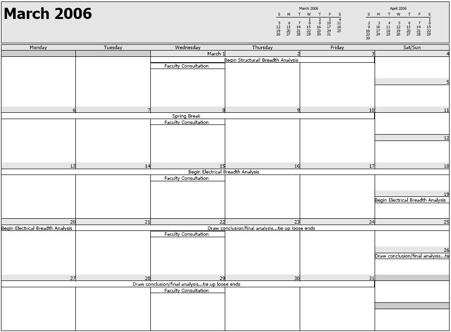
11 10.0 Tentative Schedule The following pages contain a tentative schedule for completing the proposed redesign. This schedule is subject to changes and adjustments as needed throughout the course of the Spring 2006 semester.

12

13