Pre-Mining Methane Drainage Drilling Applications
|
|
|
- Ernest Barrett
- 5 years ago
- Views:
Transcription

1 Pre-Mining Methane Drainage Drilling Applications Global Methane Initiative Coal Mine Methane And Coalbed Methane Technical Workshop June 4, 2015 Bogotá, Colombia Jonathan R. Kelafant, Advanced Resources International, Inc. Daniel Brunner, REI Drilling 1 1


2 Pre-Mining Methane Drainage Drilling Applications International CMM Industry Methane Drainage Considerations Surface Based Pre-Drainage Wells Longhole Directional Drilling Directional Drilling Equipment Drilling Capabilities Pre-Mining Applications Enhancing Gas Drainage from Lower Perm Seams Well Interception Technology and Applications Wellhead and Gas Collection Summary 2 2
3 International CMM Industry Coal is the most abundant fossil fuel. IEA predicts continued reliance and consumption of coal increasing by 50% by Mining technology continues to evolve resulting in more rapid excavation and production techniques. We continue to mine deeper, gassier and more challenging coal reserves. This has resulted in a need to improve methane drainage techniques. Use of surface drilled methane drainage wells has been affected due to surface ownership, approvals, topography, culture, lack of equipment, etc. Many coal reserves develop multiple coal seams and require flexible methane drainage approach. Gas collection systems typically use steel pipeline and demonstrate significant erosion of gas quality from wellhead to surface. There is a recognized need to mitigate methane emissions and demonstrate environmental awareness. The international CMM industry shows tremendous growth and spread of upstream and downstream technologies

4 Methane Drainage Considerations The production and recovery of methane prior to mining CBM can greatly improve mine safety and productivity. Ventilation vs. Methane Drainage Relative costs versus drainage efficiency Source of gas emissions Adjacent gas bearing strata, geologic features or working seam Geologic characterization Coal thickness, rank, stress, friability, other mechanical properties Reservoir characterization Gas content, permeability, porosity, reservoir pressure, and desorption time constant Mining technique and schedule Gate road development, start of LW, available drainage times, multiple seams Drainage approach Source, feature, or shield focused Logistics Surface and underground access Gas Utilization Alternatives, gas quality Market 4 4
5 Surface-Based Degasification Methods Vertical, Stimulated Wells. Wells drilled from the surface that are generally cased, cemented, and hydraulically stimulated. Studies by the U.S. Bureau of Mines show that up to 73% of the original gas in-place can be produced via vertical wells. These type of wells are ideally suited for multiple, thin seam situations. Horizontal Wells. These types of well are gaining in popularity and can produce 70 to 80% of the gas inplace. Good application for settings where there is one or two principal seams. 5 5
6 Design of Vertical CBM and CMM Wells 6 6

7 Why Consider Long Hole Directional Drilling? Allows longer length and more accurate placement of boreholes for improved methane drainage efficiency and longer drainage times Allows implementation of innovative pre-mining drainage techniques Ability to steer borehole to stay inseam or hit specific targets Promotes a more focused, simplified gas collection system Less labor intensive Provides additional geologic information (such as coal thickness, faults, and other anomalies, etc. prior to mining 7 7 7
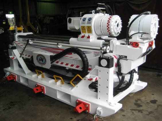
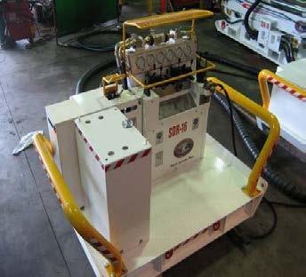
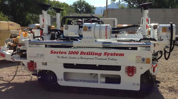
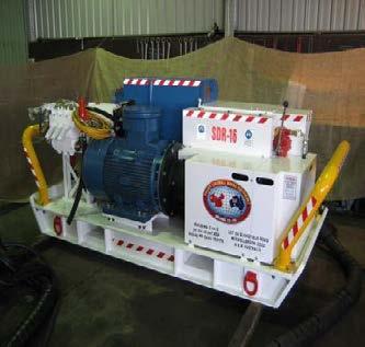
8 Directional Drilling Equipment Single Piece and Modular Units 8 8


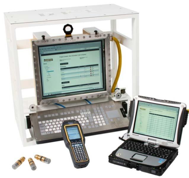
9 Directional Drilling Downhole Equipment 9 9


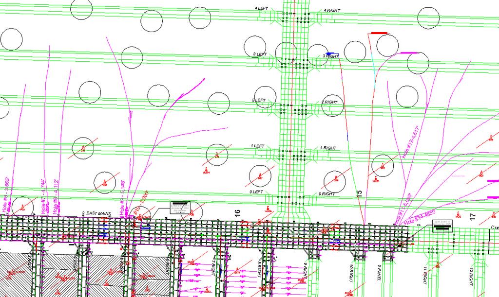
10 Drilling Capabilities Placement Accuracy N MN GN - 13 ft in 2,800 ft 10 10

11 Drilling Capabilities Reach 11 11

12 Reducing GC in Longwall Panels High Permeability 12 12

13 Reducing GC in Longwall Panels Low Permeability with Outburst Conditions 13 13

14 Reducing GC Significantly in Advance of Mining Complementary Approach with Frac Wells 14 14
15 Immediate Impact on Mining 90 Advance Rate (10's of Meters Per Month) 80 Methane Emissions (1000's of Cubic Meters Per Day) Airflow Rate (Cubic Meters Per Second) Emisson/Airflow/Advance Rate m Borehole on Production October November December January February March April May June Months in

16 Reducing GC from Adjacent Seams Profile Addressing Stability Issues Dual Purpose Boreholes 16 16

17 Reducing GC of Adjacent Seams Profile - Dual Purpose Boreholes 17 17


18 Enhancing Drainage from Lower Permeability Coals Propped fracture treatments along length of 2,500 foot boreholes Gas production increased by nearly 50% over a month Other enhanced methane drainage techniques 18 18

19 Reservoir Modeling to Assess Benefit of Hydraulic Simulation of In-Seam Boreholes 0.1 md, 50 m Spacing Fracture Locations 19 19


20 Reservoir Modeling to Assess Benefit of Nitrogen Injection 0.1 md N2 Injection Borehole (between 160 ft spaced horizontal boreholes) 20 20
 is lowered in to a surveyed target well/location. This measures the magnetic field magnitude and orientation.")
21 Well Interception Using Magnetic Ranging Technology Concept Magnetic sub installed immediately behind the bit on the downhole motor Rotating magnet generates a time varying AC magnetic field Proximity sonde (tri-axial accelerometer and multi-frequency magnetometer) is lowered in to a surveyed target well/location. This measures the magnetic field magnitude and orientation. The drill bit s position relative to the proximity sonde is triangulated based on the AC magnetic vectors. Magnetic ranging software analyzes the data and determines a corrected borehole path for the drill operator to steer to after each data collection phase. Ability to intercept a 5 inch target on any range of borehole lengths 21 21

22 Applications of Magnetic Ranging Technology Medium radius surface to in-seam drilling for pre-mining degasification of gate roads Provides for significant gas content reduction in advance of mining 150 mm diameter vertical well intercepted by 2 x 1130 m laterals 22 22

23 Applications of Magnetic Ranging Technology Underground in-seam boreholes and horizontal gob boreholes drilled in advance of longwall mining intercept vertical wells to eliminate underground gas collection systems. Intercepted vertical wells can serve as gob wells post-longwall mining 23 23


24 Wellhead and Gas Handling Gas/Water Separator During Drilling Drilling Configuration Valve and Blow Out Preventer 24 24


25 Gas Handling and Collection Post Drilling Gas/ Water Separator Gas Dilution During Drilling Both Ends of Dilution Zone Caution Signs with Fencing Coal Rib Lined with Canvas or Cement Block 20 to 300 ft Horizontal Borehole Underground Gas Pipeline with Integrity System Return Air Examination Point CH4 <1% at Exit Dilution Zone X X Caution 10 ft 25 to 50 ft Canvas Door Line Canvas with Posts (as necessary) X Caution Canvas Door Caution Gas Flow Measurement Provisions Permissible Drill Rig Return Air Proposed Dilution Zone Dilution Zone is Rock Dusted and kept free of Ignition Sources Permissible Drill Power Unit Caution Dilution Zone Return Air Caution Sign 25 25


26 Summary - Benefits of Directional Drilling Allows longer length and more accurate placement of boreholes for improved methane drainage efficiency and longer drainage times. Also allows implementation of innovative gob gas drainage techniques. Ability to steer borehole to stay inseam or hit specific targets. Provides additional geologic information (such as coal thickness/thinning, identification of faults, intrusions, and other anomalies, etc. prior to mining. Mapping and survey information
 528-8420, jkelafant@adv-res.com www.adv-res.com Daniel Brunner REI Drilling +1 (801) 270-2141, dan@reidrilling.com www.reidrilling.com www.globalmethane.org 27 27")
27 Contact Information Felicia A. Ruiz Coalbed Methane Outreach Program (CMOP) + 1 (202) , ruiz.felicia@epa.gov Jonathan Kelafant Advanced Resources International, Inc. +1 (703) , jkelafant@adv-res.com Daniel Brunner REI Drilling +1 (801) , dan@reidrilling.com