Alternatives Evaluation Report. Appendix C. Alternatives Evaluation Report
|
|
|
- Audra Newton
- 5 years ago
- Views:
Transcription
1 s Evaluation Report Appendix C s Evaluation Report I-35W North Corridor Project EA Minnesota Department of Transportation
2 Final Project s Report I-35W North Corridor Preliminary Design Project Report Version 3.0 Minnesota Department of Transportation Metro District Prepared by: Date: May 2016 SRF No. 8598
3 Table of Contents Chapter 1 Introduction Report Purpose Existing Conditions Chapter 2 Project Planning History Interstate 35 Corridor Management Plan (CMP) (2005) MnPASS System Studies MnPASS System Study Phase 1 (2005) MnPASS System Study Phase 2 (2010) Metropolitan Highway System Investment Study (2010) I-35W North Managed Lanes Corridor Study (2013) Chapter 3 s Scoping Transit s Light Rail Transit (LRT) Bus Rapid Transit (BRT) Highway Design s General Purpose Lane Capacity Improvements One Additional Travel Lane in Each Direction on I-35W Localized Improvements on I-35W Chapter 4 s to Be Studied In the EA No Build I-35W North Corridor Build s General Purpose Lane High Occupancy Vehicle (HOV) Lane MnPASS Lane Chapter 5 s Evaluation Process Evaluation Process Evaluation Criteria Phase 1: Evaluation of Operations Concepts Final Project s Report i I-35W North Corridor Preliminary Design Project
4 5.2.2 Phase 2: Recommended Design Decisions Chapter 6 s Evaluation Phase 1 Evaluation Results (Build Operations Concepts) Do the s Address the Project Need? Do the s Address Additional Project Goals and Objectives? What are the Social, Economic and Environmental (SEE) Impacts of the s? What is the Recommended? Phase 2 Evaluation Results (Spot Mobility Improvements to Address Localized Areas of Congestion) Description of I-35W Spot Mobility Improvements Spot Mobility Improvement Evaluation Methodology Spot Mobility Improvement Evaluation Results Spot Mobility Safety Benefits and I-694 Interchange Safety Assessment Recommended Spot Mobility Improvements Identification of the Preferred Layout Preferred Pavement Improvements Preferred MnPASS Lane Addition Preferred Bridge Replacement Preferred Spot Mobility Improvements Appendix A: Appendix B: Appendix C: Level of Service Tables Level of Service Figures Spot Mobility Improvements Heat Maps H:\Projects\8598\Environmental\Reports\2_s\Final Alt Report\4_Final\ _35W_North_Final-Alt- Rpt_ docx Final Project s Report ii I-35W North Corridor Preliminary Design Project
5 List of Tables and Figures List of Tables Table 3.1 I-35 CMP, Scenario C Added Roadway Capacity, Year Table 3.2 I-35W Added Roadway Capacity, Year 2040 Traffic Volumes Table 5.1 s Evaluation Criteria (Phase 1) Table 6.1 I-35W Year 2040 Forecast Traffic Volumes (Vehicles Per Day) Table 6.2 Southbound I-35W Morning Peak Hour Person Throughput Table 6.3 Northbound I-35W Afternoon Peak Hour Person Throughput Table 6.4 Travel Time Savings (Delay Per User) Table 6.5 Year 2040 Transit Ridership Forecasts (Riders Per Day) Table 6.6 Year 2040 Bus Travel Time Savings Versus General Purpose Lanes Table 6.7 HOV Advantages Table 6.8 Consistency with State and Regional Transportation Plans Table 6.9 Benefit Cost Analysis Results Table 6.10 I-35W North Corridor Preliminary Design Project s Evaluation Matrix Table 6.11 Basis for Recommended Decision Table 6.12 I-35W Spot Mobility Improvements Table 6.13 Southbound I-35W PM Peak Period Lane-Mile Hours (Improvement #1 + Improvement #4 + Auxiliary Lane) Table 6.14 Southbound I-35W PM Peak Period Lane-Mile Hours (Improvement #1 + Improvement #4 + Auxiliary Lane + Improvement #10) Table 6.15 Northbound I-35W PM Peak Period Lane-Mile Hours (Improvement #7 + Improvement #9A/#9B + Improvement #11) Table 6.16 Recommended Spot Mobility Improvements Final Project s Report iii I-35W North Corridor Preliminary Design Project
6 List of Figures Figure 1.1 Project Location Map Figure 1.2 I-35W (Existing Six-Lane Rural Section Roadway) Figure 1.3 I-35W (Existing Eight-Lane Roadway with Concrete Median Barrier) Figure 1.4 I-35W (Existing Four-Lane Rural Section Roadway) Figure 2.1 MnPASS System Study Phase Figure 2.2 MnPASS System Study Phase Figure 2.3 Metropolitan Highway System Investment Study Managed Lane Universe of Projects Figure Transportation Policy Plan. Map of Current Revenue Scenario Transitways and CTIB Phase I of Program Projects Figure 4.1 General Purpose Lane Figure 4.2 HOV Lane Figure 4.3 MnPASS Lane Figure 5.1 s Evaluation Process Figure 6.1 Year 2040 Level of Service (LOS) Summary Figure 6.2 Travel Time Reliability Analysis Results (Reliability by Person Trips) (Morning and Afternoon Peak Periods) Figure 6.3 I-35W North Corridor s Screening Results Figure 6.4 Spot Mobility Improvements Overview Map Figure 6.5 Southbound I-35W at I-694 Lane-By-Lane Speed Differential (Morning Peak Hour) Figure 6.6 Southbound I-35W at I-694 Lane-By-Lane Speed Differential (Morning Peak Hour) (With Improvement #2 and Improvement #3) Figure 6.7 Northbound I-35W at I-694 Lane-By-Lane Speed Differential (Afternoon Peak Hour) Figure 6.8 Northbound I-35W at I-694 Lane-By-Lane Speed Differential (Afternoon Peak Hour) (With Improvement #9A and Improvement #12) Figure 6.9 Preferred Layout Final Project s Report iv I-35W North Corridor Preliminary Design Project
7 Introduction Chapter 1 Introduction 1.1 Report Purpose The purpose of this Project s Report is to document the alternatives scoping and evaluation process for the Interstate Highway 35W (I-35W) North Corridor Preliminary Design Project (SP ). The I-35W North Corridor Preliminary Design Project is located in Anoka and Ramsey Counties in the cities of Roseville, New Brighton, Arden Hills, Mounds View, Shoreview, Lexington, Blaine and Lino Lakes (see Figure 1.1). The Final Project s Report includes a discussion of: Project Planning History s Scoping s to be Studied in the Environmental Assessment s Evaluation Process and Criteria Identification of a Preferred This document was prepared as part of the federal and state environmental review processes for the Project. The details of the alternatives identification, alternatives scoping, and alternatives evaluation process described in this report will be summarized in the environmental documentation for the Project. At the federal level, the Project is anticipated to be reviewed as a Class III action (Environmental Assessment) (EA) under the National Environmental Policy Act (NEPA). At the state level, the project meets the mandatory threshold for preparation of an Environmental Assessment Worksheet (EAW). It is anticipated that the environmental document for the Project will be a combined federal EA/state EAW. The purpose and need for the Project is documented in a separate memorandum available for review from the Minnesota Department of Transportation (MnDOT) Metro District. The purpose of the project is to provide a long-term, sustainable option for all highway users (transit and non-transit) that improves pavement conditions, increases mobility, improves travel time reliability, and maintains or improves transit advantages on I-35W between TH 36 and Sunset Avenue (County Road 53). In addition, state and regional transportation plan policies and strategies, including goals and objectives to better utilize existing and future infrastructure investments will help guide project development. Final Project s Report 1-1 I-35W North Corridor Preliminary Design Project
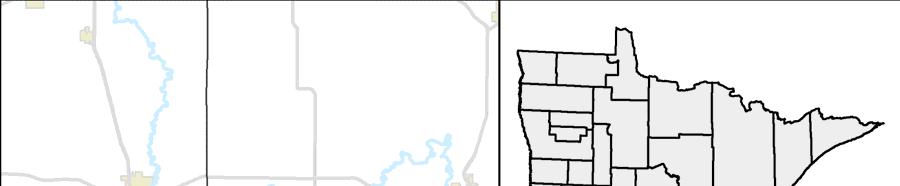
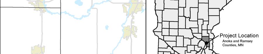
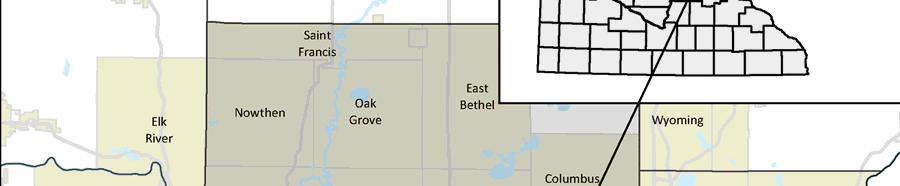
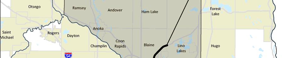
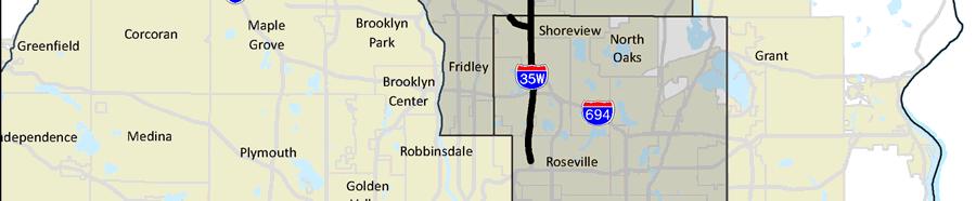
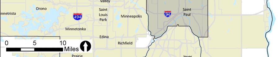
8 Introduction Figure 1.1 Project Location Map Final Project s Report 1-2 I-35W North Corridor Preliminary Design Project
9 Introduction Segments of the I-35W project corridor currently experience recurring congestion during the morning and afternoon peak travel periods. This congestion is expected to increase in the future as additional growth and development occur in communities along I-35W and the greater Twin Cities Metropolitan Region, resulting in increases in travel times for vehicles, transit, and freight. Additional goals and objectives include consistency with regional transportation plans; utilizing existing and future infrastructure investments and addressing bridge preservation needs where feasible; and fiscal considerations regarding project cost. The southern project terminus is the TH 36 interchange. The northern project terminus is the Lake Drive interchange (County State Aid Highway (CSAH) 23). These termini were identified based on the need for the project as well as other considerations. The rationale for identifying the TH 36 and Lake Drive interchanges as the project termini are documented in a separate logical termini memorandum, available for review from the MnDOT Metro District. 1.2 Existing Conditions The I-35W North project corridor between TH 36 and CSAH 23 consists of three main types of roadways as summarized below. Typical sections for these three segments of I-35W are shown in Figure 1.2, Figure 1.3 and Figure 1.4. A six-lane rural freeway (three lanes in the northbound direction and three lanes in the southbound direction) from TH 36 to the I-35W/TH 10 commons area, and from the I-35W/TH 10 commons area to County Road (CR) J. A center median ditch separates the northbound and southbound lanes (see Figure 1.2). An eight-lane urban freeway (four lanes in the northbound direction and four lanes in the southbound direction) in the I-35W/TH 10 commons area. A concrete median barrier separates the northbound and southbound lanes (see Figure 1.3). A four-lane freeway (two lanes in the northbound direction and two lanes in the southbound directions) north of CR J. A center median ditch separates the northbound and southbound lanes (see Figure 1.4). Final Project s Report 1-3 I-35W North Corridor Preliminary Design Project
 There are multiple locations throughout the project corridor where auxiliary lanes are present, shoulder widths may vary, and")

10 Introduction Figure 1.2 I-35W (Existing Six-Lane Rural Section Roadway) Figure 1.3 I-35W (Existing Eight-Lane Roadway with Concrete Median Barrier) Figure 1.4 I-35W (Existing Four-Lane Rural Section Roadway) There are multiple locations throughout the project corridor where auxiliary lanes are present, shoulder widths may vary, and other roadway features may be present. For example, the I-35W/TH 10 commons area consists of a sixlane roadway with a center median barrier and a rural section to the outside shoulders. The northbound and southbound lanes south of the I-35W/ TH 10 commons area are separated by a cable median barrier. Final Project s Report 1-4 I-35W North Corridor Preliminary Design Project
11 Project Planning History Chapter 2 Project Planning History Within the past decade, MnDOT has completed numerous planning studies that include the I-35W project corridor from TH 36 to Lexington Avenue. These previous planning studies include: Interstate 35 Corridor Management Plan (2005) MnPASS System Study Phase 1 (2005) MnPASS System Study Phase 2 (2010) Metropolitan Highway System Investment Study (2010) I-35W North Managed Lanes Corridor Study (2013) The purpose of these planning studies and the major findings with respect to the I-35W project corridor is summarized below Interstate 35 Corridor Management Plan (CMP) (2005) MnDOT completed the Interstate 35 Corridor Management Plan (CMP) in The purpose of the CMP study was to develop a long-term corridor vision for I-35, including I-35W and I-35E, from the I-494/I-694 beltway in the Twin Cities Metropolitan Area to TH 48 in Hinckley, Minnesota. The vision identified in the CMP was focused on preserving and enhancing safety and mobility on I-35. The Corridor Vision Statement identified in the 2005 CMP is presented below. Interstate 35 (I-35) is a nationally recognized corridor that provides essential transportation connections within the United States, it connects Duluth and other northeastern Minnesota communities, and it connects northern recreational areas in both Minnesota and Wisconsin to the Twin Cities metropolitan area. In addition to connecting communities along and near the corridor, I-35 serves as a conduit for moving commercial, agricultural and manufacturing products and materials, and it serves commuters within the Twin Cities metropolitan area. Chapter 5 of the I-35 CMP identifies study findings and recommendations. One of the findings of the CMP study was that volumes in the southern part 1 Copies of previous planning studies are available for review by contacting the MnDOT Project Manager for the I-35W North Corridor Preliminary Design Project (Jerome Adams, jerome.adams@state.mn.us or ). Final Project s Report 2-1 I-35W North Corridor Preliminary Design Project
12 Project Planning History of the corridor between I-694 and Lexington Avenue exceed the capacity of I-35W, and that future traffic demand (year 2030 volumes) is expected to be substantially greater than existing capacity as development occurs along I-35W. In order to accomplish the overall corridor vision and address capacity and safety issues on the corridor, a number of improvements were identified in the I-35 CMP, including expanding the number of lanes on I-35W between I-694 and Lexington Avenue (see Section 3.2.1). It is important to note that the I-35 CMP acknowledged that the number of additional lanes and transit service needed on I-35W to achieve performance goals exceeded the levels identified in the Metropolitan Council s Transportation Policy Plan. 2.2 MnPASS System Studies Recognizing that the Twin Cities Metropolitan Area cannot build its way out congestion through capacity expansion alone because of fiscal and other constraints (e.g., right of way, environmental), state and regional transportation plans and policies have shifted towards strategies designed to mitigate congestion and maximize person throughput on the highway system, including a system of managed lanes. In support of this, MnDOT and the Metropolitan Council have completed several studies over the past decade to identify the best candidates for managed lane projects, beginning with the MnPASS System Studies MnPASS System Study Phase 1 (2005) MnDOT completed the MnPASS System Study Phase 1 in The overall goal of the MnPASS System Study Phase 1 was to identify a potential MnPASS tolling lane system for highways within the Twin Cities Metropolitan Area and provide MnDOT and the Metropolitan Council with information on cost, operational, revenue, and other implications of a MnPASS System. At the time the MnPASS System Study Phase 1 was being completed, MnDOT was in the process of implementing the first MnPASS lanes on I-394 between I-494 and downtown Minneapolis. MnPASS is the term used by MnDOT to describe express toll lanes managed toll lanes in which single-occupancy vehicles are required to pay a fee. Transit and highoccupancy vehicles use the MnPASS lane without paying a fee. MnPASS lanes are dynamically priced such that free-flow, uncongested conditions are maintained by increasing the fee as traffic volume in the MnPASS lanes increases. One of the products developed as part of the Phase 1 System Study was a map of potential MnPASS projects that could be developed within the next 25 years. The proposed 2030 MnPASS Vision Map is shown below in Final Project s Report 2-2 I-35W North Corridor Preliminary Design Project

13 Project Planning History Figure 2.1, and includes the segment of I-35W between TH 36 and TH 10. The MnPASS System Study Phase 1 Final Report stated the following regarding MnPASS projects. 2 The 2030 Vision Map represents current thinking on where MnPASS lanes would be the most effective; however, other future capacity expansions could be considered as MnPASS lanes and connected to the system as well. Figure 2.1 MnPASS System Study Phase 1 Source: Minnesota Department of Transportation. April MnPASS System Study Phase 1 Final Report prepared by Cambridge Systematics, Inc. with URS Corporation. Figure 11. Potential MnPASS 2030 Vision. 2 Minnesota Department of Transportation. April MnPASS System Study Phase 1 Final Report prepared by Cambridge Systematics, Inc. with URS Corporation. Page ES-12 Executive Summary. Final Project s Report 2-3 I-35W North Corridor Preliminary Design Project
14 Project Planning History MnPASS System Study Phase 2 (2010) The MnPASS System Study Phase 2 was completed by MnDOT in The MnPASS System Study Phase 2 was prepared to reassess short-term MnPASS system investments in light of Federal policies, experiences with the two existing MnPASS facilities on I-394 and I-35W, and in coordination with the Metropolitan Highway System Investment Study (see Section 2.3). The findings of this study update were documented in the MnPASS System Study Phase 2 Final Report (2010). 3 The purpose of the MnPASS Phase 2 System Study was to analyze and make recommendations for MnPASS managed lane projects in the Twin Cities Metropolitan Area, including new locations for MnPASS lanes. Unlike the Phase 1 System Study, the Phase 2 System Study prioritized implementation of MnPASS corridors. Projects were divided into three tiers, from short-term priorities (Tier 1) to long-term opportunities (Tier 3). The MnPASS System Study Phase 2 Final Report identified the I-35W corridor as a Tier 2, mid-term project (Downtown Minneapolis to TH 36, and TH 36 to Blaine, see Figure 2.2), and stated the following regarding the advantages and challenges of the I-35W corridor. 4 This corridor has strong benefits and among the strongest transit service. It can be connected directly to downtown Minneapolis. It can be built in two subsections with independent utility and can be connected to Corridor 1A (eastbound TH 36), thereby creating a strong MnPASS system serving the northern part of the Metro region. There is an active corridor stakeholder group that is advocating for improvements to this corridor. However, this corridor is expensive to build with considerable engineering risks to be resolved. 3 A copy of the MnPASS System Study 2 Final Report is available on the MnDOT MnPASS website at 4 Minnesota Department of Transportation. September MnPASS System Study Phase 2 Final Report prepared by Cambridge Systematics, Inc. Page ES-5 Executive Summary. Final Project s Report 2-4 I-35W North Corridor Preliminary Design Project

15 Project Planning History Figure 2.2 MnPASS System Study Phase 2 Source: Minnesota Department of Transportation. September MnPASS System Study Phase 2 Final Report prepared by Cambridge Systematics, Inc. Figure 2.2. Corridor Location Map. 2.3 Metropolitan Highway System Investment Study (2010) At the same time the MnPASS Phase 2 System Study was being completed in 2010, the Metropolitan Council and MnDOT also completed the Metropolitan Highway System Investment Study (MHSIS). 5 The purpose of 5 The Metropolitan Highway System Investment Study Final Report (2010) is available on the Metropolitan Council website at Resources/Metropolitan-Highway-System-Investment-Study-(MHSI.aspx. Final Project s Report 2-5 I-35W North Corridor Preliminary Design Project
16 Project Planning History this study was to develop a future transportation investment strategy that optimizes investments already made in the Twin Cities region through the use of multimodal oriented managed lanes and comprehensive system management strategies. The MHSIS focused on the use of management strategies as a possible alternative to costly general purpose capacity expansion. The purpose of these management strategies, as described in the MHSIS final report, was not to fix congestion problems, but to provide users with a continuously congestion-free alternative throughout the regional highway system. The MHSIS rated 18 potential managed lane corridors using four categories of performance measures (see Figure 2.3). The corridors were ranked relative to one another based on a composite performance rating of high, medium, or low. Higher ranked corridors best corresponded with the goals and objectives of MHSIS for assumed potential implementation by year The MHSIS ranked the I-35W north corridor with a high rating and concluded the following regarding to the I-35W north corridor from downtown Minneapolis to 95th Avenue in Blaine: 6 I-35W north is one of the strongest transit corridors for the managed lane system, and deserves special consideration here. In addition to its transit suitability, this corridor has moderate-to-high ratings for performance, including throughput, optimization and SOV travel reduction. The ability to serve regional and inter-regional trips on the managed lane system is high, with close connections to I-394 and I-35W to the south. Finally, given the presence of existing bus-only-shoulder operations, the ability to convert this facility to managed lanes is strong. 6 Metropolitan Council. September Metropolitan Highway System Investment Study Final Report prepared by Parsons Brinkerhoff. Page Managed Lanes Plan. Final Project s Report 2-6 I-35W North Corridor Preliminary Design Project


17 Project Planning History Figure 2.3 Metropolitan Highway System Investment Study Managed Lane Universe of Projects Source: Metropolitan Council. September Metropolitan Highway System Investment Study Final Report prepared by Parsons Brinkerhoff. Figure 1. Managed Lane Universe of Projects. 2.4 I-35W North Managed Lanes Corridor Study (2013) MnDOT completed the I-35W North Managed Lanes Corridor Study in The purpose of this study was to identify and evaluate lowercost/high-benefits options for improving traffic operations along I-35W and I-35 between downtown Minneapolis and the Columbus/Forest Lake area, evaluate options for providing a managed lane in the corridor, and consider 7 The I-35W North Managed Lanes Corridor Study Final Report (2013) is available on the MnDOT website at Final Project s Report 2-7 I-35W North Corridor Preliminary Design Project
18 Project Planning History how improvements could be strategically implemented over time. The study identified improvement strategies to address the following four goals: Reduce congestion and improve safety along the corridor. Better utilize existing infrastructure investments. Increase transit ridership and the use of high occupancy vehicles by providing travel time advantages. Provide a choice for commuters during the peak periods. The I-35W North Managed Lanes Corridor Study included an evaluation of existing traffic operations problems, travel demand forecasting for existing (year 2010/2011) and future (year 2030) conditions, and an evaluation of managed lane alternatives. A No-Build and four different corridor managed lane alternatives were evaluated using a multi-step evaluation process. Through this evaluation process, a viable managed lane alternative was identified that would include construction of a managed lane along the inside shoulder of I-35W between downtown Minneapolis and Lexington Avenue. The study also considered a bus rapid transit alternative and concluded that the I-35W north corridor may be able to support all-day, station-to-station bus rapid transit service under the future year 2030 conditions assumed in the analysis. The final outcome of the I-35W North Managed Lanes Corridor Study was the I-35W North Managed Lanes Vision. The I-35W North Managed Lanes Vision represents the entire range of improvements identified for the I-35W corridor, including additional managed lane capacity, localized improvements to address existing congestion problems, and localized improvements to facilitate the implementation of managed lanes. The study stated the following regarding the I-35W North Managed Lanes Vision: 8 It is understood that the full Managed Lanes Vision cannot be completed as a single project. It will take many years of separate phases to be realized. The purpose of identifying the Managed Lanes Vision was to ensure that as improvements are made through the corridor, they support and build toward the vision while providing benefits to corridor users with each new improvement. 8 Minnesota Department of Transportation. June I-35W North Managed Lanes Corridor Study Final Report prepared by SRF Consulting Group, Inc. in conjunction with Kimley-Horn & Associates, Inc. and ZAN Associates, Inc. Page ES-16 Managed Lanes Vision. Final Project s Report 2-8 I-35W North Corridor Preliminary Design Project
19 s Scoping Chapter 3 s Scoping Chapter 3 of this Final Project s Report describes the alternatives scoping process for the I-35W North Corridor Preliminary Design Project. This alternatives scoping process relied on results from previous planning studies and current transportation plans to funnel down a wide range of alternatives to three build alternatives identified for further evaluation in the EA. 3.1 Transit s Two transit modes were considered during the I-35W North Corridor Preliminary Design Project alternatives scoping: light rail transit (LRT) and bus rapid transit (BRT) Light Rail Transit (LRT) A light rail transit (LRT) option was considered but will not be studied in the EA. LRT operates on tracks and requires an exclusive running way and station infrastructure. Previous studies, including the I-35W Managed Lanes Corridor Study, concluded that transit ridership is not anticipated to be sufficient to warrant a LRT transitway within the I-35W right of way. 9 The I-35W Managed Lanes Corridor Study and the Metropolitan Council s 2040 Transportation Policy Plan (TPP) identify bus rapid transit, not LRT, as a potential future transit investment for the I-35W north corridor Bus Rapid Transit (BRT) The 2013 I-35W North Managed Lanes Corridor Study investigated a bus rapid transit (BRT) scenario to ensure that the development of a managed lane on I-35W would not preclude a potential BRT corridor in the future. The I-35W North Managed Lanes Corridor Study investigated highway BRT, where buses operate on a limited access highway and can use bus-only shoulders, MnPASS lanes, ramp meter bypasses, and priced dynamic 9 Minnesota Department of Transportation. June I-35W North Managed Lanes Corridor Study Final Report prepared by SRF Consulting Group, Inc. in conjunction with Kimley-Horn & Associates, Inc. and ZAN Associates, Inc. Page 81 Managed Lanes Study Framework. Final Project s Report 3-1 I-35W North Corridor Preliminary Design Project
20 s Scoping shoulders as transit advantages. The study came to a number of conclusions regarding the I-35W corridor and BRT service: 10 Managed lanes provide travel time benefits to express bus service, resulting in higher ridership, and would help facilitate possible BRT service. The I-35W north corridor may be able to support all-day, station-tostation BRT service in year 2030 under the conditions assumed in this evaluation. Ridership forecasts were more sensitive to service frequency than to differences in corridor travel times associated with providing online stations. Minor differences in forecasted ridership totals would not be expected to justify the high capital costs associated with a BRT system using online stations. Construction of managed lanes can proceed without precluding future development of a BRT system that utilizes inline and offline stations. Chapter 6 of the Metropolitan Council s 2040 Transportation Policy Plan describes regional transitway priorities based on expected revenues and project planning status. The I-35W north corridor is not identified as a transitway investment priority under the Metropolitan Council s Current Revenue Scenario (see Figure 3.1). However, the I-35W north corridor is identified as a potential transitway corridor under the Metropolitan Council s Increased Revenue Scenario. This Increased Revenue Scenario assumes additional funding for transitways such that the complete transitway vision for the Twin Cities region could be implemented by year Under this scenario, corridors such as the I-35W north corridor would need to complete a locally preferred alternative recommendation before being considered for prioritization and funding. For these reasons, a BRT option will not be studied in the EA. However, the I-35W North Corridor Preliminary Design Project will be planned and developed in such manner that future BRT is not precluded from the corridor. 10 Minnesota Department of Transportation. June I-35W North Managed Lanes Corridor Study Final Report prepared by SRF Consulting Group, Inc. in conjunction with Kimley-Horn & Associates, Inc. and ZAN Associates, Inc. Page 97 Bus Rapid Transit Evaluation. Final Project s Report 3-2 I-35W North Corridor Preliminary Design Project


21 s Scoping Figure Transportation Policy Plan. Map of Current Revenue Scenario Transitways and CTIB Phase I of Program Projects Source: Metropolitan Council. January Transportation Policy Plan. Chapter 6: Transit Investment Direction and Plan. Figure 6-6. Map of Current Revenue Scenario Transitways and CTIB Phase I of Program Projects. 3.2 Highway Design s Two general highway design alternatives were considered during scoping. The first included general purpose lane capacity improvements (i.e., adding multiple general purpose lanes in each direction of I-35W). The second included one additional lane in both directions on I-35W. This second design alternative also considered multiple operations concepts (general purpose, high occupancy vehicle, MnPASS) for use of the additional lane General Purpose Lane Capacity Improvements As discussed in Chapter 2 of this report, the recommendations from the I-35 CMP included general purpose lane capacity improvements. These improvements ranged from adding two to four general purpose lanes on I-35W to meet performance targets and provide capacity beyond year 2030 traffic forecasts (see Table 3.1). Final Project s Report 3-3 I-35W North Corridor Preliminary Design Project
22 s Scoping Roadway capacity improvements that include multiple general purpose lanes in each direction on I-35W was considered but will not be evaluated in the EA. This option has been eliminated from further consideration based on previous planning studies as well as studies performed as part of the current project. These analyses concluded that it would be cost prohibitive to provide the number of general purpose lanes necessary to meet the mobility and reliability needs of the corridor. While the additional travel lanes could be accommodated within existing highway right of way, there is not adequate space to also accommodate the infrastructure needed to treat stormwater runoff from the new impervious surfaces. The physical constraints of the corridor prohibit the number of lanes and associated stormwater management features (e.g., stormwater ponds, infiltration basins) that could be added without incurring substantial social (right of way) and potential environmental impacts. I-35 Corridor Management Plan (2005) The I-35 CMP developed and analyzed three improvement scenarios for the I-35 corridor (Scenario A, Scenario B, and Scenario C), and included transit and mainline highway capital improvements. These scenarios were developed by varying the amount of transit use and number of mainline lanes needed to meet the performance target of 45 MPH on I-35W north of I-694. Scenario C placed an emphasis on highway improvements that would provide capacity beyond traffic forecasts for year Scenario C improvements were recommended for I-35 by the CMP Study Team and Advisory Committees. The number of additional lanes needed on I-35W between I-694 and Lexington Avenue under this scenario is summarized in Table 3.1. Table 3.1 I-35 CMP, Scenario C Added Roadway Capacity, Year 2030 I-35W Segment (1) Total # of Existing Lanes Added Roadway Capacity (Year 2030 Capacity) I-694 to CSAH 10 6 Yes (add 4) 10 CSAH 10 to TH 10 8 Yes (add 4) 12 TH 10 to Lake Drive 6 Yes (add 2) 8 Lake Drive to Lexington Avenue 4 Yes (add 4) 8 Total # of Lanes (Year 2030 Capacity) Source: Minnesota Department of Transportation Interstate 35 Corridor Management Plan. Table 3-2, Scenario C: Additional Mainline Lanes/Additional Transit. (1) The southern limit of the I-35 CMP was the I-494/I-694 beltline and did not include an analysis of I-35W south of the I-694 interchange. Final Project s Report 3-4 I-35W North Corridor Preliminary Design Project
23 s Scoping I-35W North Managed Lanes Corridor Study (2013) Planning-level cost estimates prepared for the I-35 CMP were revisited in 2013 as part of the I-35W North Managed Lanes Corridor Study. The purpose of this analysis was to estimate project costs for the segment of I-35W from 4th Street in downtown Minneapolis to I-694 using the same methodology as the I-35 CMP, identify the total project cost for the I-35W corridor from downtown Minneapolis to TH 97, and adjust I-35 CMP cost estimates for inflation (year 2012 dollars). This analysis assumed a total of 10 lanes on I-35W between 4th Street in Minneapolis and CSAH 10 in Mounds View/Arden Hills (five lanes in each direction). Cost estimates included additional lane construction, interchange and bridge replacements, noise barriers and retaining walls, and right of way costs. The total project cost for I-35W from 4th Street in downtown Minneapolis to TH 97 in the Columbus/Forest Lake area was estimated to be approximately $1.7 billion (year 2012 dollars). 11 The I-35W project segment between TH 36 and Lexington Avenue was estimated at more than 50 percent of this total cost, or approximately $981 million (year 2012 dollars). The I-35W North Managed Lanes Corridor Study concluded that it would not be financially feasible to construct the level of improvements identified in the I-35 CMP. I-35W North Corridor Preliminary Design Project Analysis (2015) The analysis completed as part of the I-35W North Managed Lanes Corridor Study was revisited as part of the current I-35W North Preliminary Design Project. A planning-level assessment was completed to identify the improvements necessary on I-35W to accommodate congestion-free conditions under projected year 2040 traffic volumes. The number of I-35W travel lanes and other corridor improvements are summarized in Table 3.2. The findings of this assessment were consistent with the highway improvements identified in the I-35 CMP. 11 Minnesota Department of Transportation. June I-35W North Managed Lanes Corridor Study Final Report prepared by SRF Consulting Group, Inc. in conjunction with Kimley-Horn & Associates, Inc. and ZAN Associates, Inc. Pages Managed Lanes Study Framework. Final Project s Report 3-5 I-35W North Corridor Preliminary Design Project
24 s Scoping Table 3.2 I-35W Added Roadway Capacity, Year 2040 Traffic Volumes I-35W Segment (1) Total # of Existing Lanes Added Roadway Capacity (Year 2040 Capacity) Lexington Avenue to Lake Drive 4 Yes (add 2) 6 Lake Drive to TH 10 (West) (1) 6 Yes (add 2) 8 TH 10 (West) to TH 10 (East) 8 Yes (add 4) 12 TH 10 (East) to CR 88 (2) (3) 6 Yes (add 4) 10 CR 88 to TH 36 6 Yes (add 2) 8 (1) Includes construction of a new auxiliary lane on westbound TH 10 from I-35W to 93rd Lane. (2) Includes reconstruction of the I-35W/I-694 interchange. Total # of Lanes (Year 2040 Capacity) (3) Includes construction of two-lane exit ramp from southbound I-35W to eastbound TH 10 and a two-lane entrance ramp from westbound TH 10 to northbound I-35W. The additional travel lanes described in Table 3.2 would result in additional impervious surface within the I-35W corridor. Stormwater runoff from the existing and new travel lanes would need to be conveyed and treated as required by water quality regulations. While the number of additional travel lanes identified in Table 3.2 could likely physically fit within the existing I-35W right of way, there is not adequate space within the right of way to accommodate both the travel lanes and associated stormwater management infrastructure (e.g., stormwater ponds, infiltration basins). Therefore, additional right of way would need to be acquired, impacting adjacent homes and businesses One Additional Travel Lane in Each Direction on I-35W As noted above, a highway design option that included multiple general purpose lanes was considered but will not be studied in the EA. Previous and current studies have concluded that it is not financially or physically feasible to construct the necessary number of additional general purpose lanes needed to address mobility and congestion-related problems on the I-35W project corridor. While construction of multiple additional travel lanes is not feasible, it is fiscally and physically feasible to construct one additional travel lane in each direction of I-35W between TH 36 and Lexington Avenue. Concept cost estimates completed for the I-35W Managed Lanes Corridor Study for a managed lane between TH 36 and Lexington Avenue were approximately $140 million (2012 dollars). Construction of one additional lane can be accommodated within the existing highway right of way by constructing within the center median, minimizing social and environmental impacts to surrounding properties and resources. Final Project s Report 3-6 I-35W North Corridor Preliminary Design Project
25 s Scoping As described in Chapter 2, previous planning studies have envisioned that the additional lane along northbound and southbound I-35W would operate as a MnPASS Lane. However, previous planning studies did not perform a comparison of the MnPASS Lane to other lane operations concepts. Therefore, three lane operations concepts have been identified for study in the EA. These alternatives were identified for study in the EA because they represent a reasonable range of alternatives, and include: General Purpose Lane High Occupancy Vehicle (HOV) Lane MnPASS Lane Additional details regarding these alternatives are described in Chapter 4 (s to be Studied in the EA) Localized Improvements on I-35W The I-35W Managed Lanes Corridor Study included an evaluation of a number of concepts to address existing congestion problems at specific locations along the I-35W corridor between downtown Minneapolis and TH 97. Within the current project limits, this included an evaluation of localized concepts at the I-35W/I-694 interchange, the I-35W/CR I interchange, and the I-35W/TH 10 interchange. Concepts were developed at these locations using low-cost/high-benefit strategies (i.e., maximize use of existing and future infrastructure investments). Localized improvements do not address the purpose and need of the project. While localized improvements address traffic operations concerns and improve performance along specific segments of the corridor, they do not improve mobility, reliability, and transit advantages along the entire project corridor from TH 36 to Lexington Avenue. As stated in the I-35W Managed Lanes Corridor Study, these concepts were developed to be complementary and not preclude development of an additional travel lane along the project corridor. Once a recommended alternative has been identified, additional traffic and engineering studies will be completed to evaluate geometric design alternatives at specific locations along the project corridor. These localized geometric enhancements will be evaluated based on traffic operations and will be incorporated into the project design where feasible based on financial and physical/environmental constraint considerations (see also Section 5.2.2). Final Project s Report 3-7 I-35W North Corridor Preliminary Design Project
26 s to be Studied in the EA Chapter 4 s to Be Studied In the EA Chapter 4 of this Final Project s Report describes the alternatives to be studied in the EA. In addition to the No Build, three Build s will be studied in the EA. The Build s represent different operations concepts for one additional travel lane in each direction on I-35W between TH 36 and Lexington Avenue. Specific features of each Build are described greater detail below. 4.1 No Build The No Build would maintain the current lane configuration on I-35W along the approximately 12 mile project corridor from north of TH 36 to the Sunset Avenue overpass (see roadway typical sections in Section 1.2). The existing roadway shoulder would continue to be utilized as a bus only shoulder between CR C and 95th Avenue (CSAH 52), and buses would be subject to applicable operating rules. The No Build would be limited to ongoing maintenance work along the I-35W project corridor, as well as other programmed improvements in the State Transportation Improvement Program (STIP) listed below. SP CR H bridge and interchange construction SP replace CR E2 bridge over I-35W SP mill and overlay from CR C to I I-35W North Corridor Build s Three Build s were considered for the I-35W North Corridor Preliminary Design Project, representing different operations concepts for an additional travel lane in the northbound and southbound directions on I-35W from north of TH 36 in Roseville to Lexington Avenue in Blaine. All three of the Build s also include pavement rehabilitation on I-35W between CR C in Roseville and Sunset Avenue in Lino Lakes. The three Build operations concepts include: General Purpose Lane High Occupancy Vehicle (HOV) Lane MnPASS Lane Final Project s Report 4-1 I-35W North Corridor Preliminary Design Project
27 s to be Studied in the EA The three Build s described below would maintain the I-35W corridor in its current alignment. There are no alternatives to relocate the freeway as this would result in substantial social, economic, and environmental impacts. From a geometric design perspective, each of the three Build s is largely the same. Each includes the construction of a new travel lane in both the northbound and southbound directions within the center median of the I-35W project corridor. The existing centerline spacing between northbound I-35W and southbound I-35W would also remain the same. The only difference is the width of the inside shoulder. With the General Purpose Lane, the inside shoulder width is 8.9 feet. Under the HOV Lane and MnPASS Lane, the inside shoulder width is 6.9 feet. Construction of the additional lane within the center median, as recommended in the 2013 I-35W North Managed Lanes Corridor Study Final Report, maximizes the use of existing highway right of way and minimizes potential impacts to adjacent properties. Environmental differences between the Build s are expected to be similar for such items as traffic noise, wetlands, right of way, water quality, etc. The difference between the three Build s lies in the use and operation of the additional travel lanes (General Purpose, HOV, MnPASS) as described below General Purpose Lane The General Purpose Lane includes construction of a new northbound and southbound travel lane within the center median of I-35W between TH 36 and Lexington Avenue. The general purpose lanes would have no restrictions on use (i.e., accessible to all vehicles, transit, and freight). Under the General Purpose Lane, no fee would be charged for motorists to use this lane. The existing bus only shoulders would also continue to remain in operation under the General Purpose Lane. Figure 4.1 illustrates the typical configuration of the GP Lane. Final Project s Report 4-2 I-35W North Corridor Preliminary Design Project
28 s to be Studied in the EA Figure 4.1 General Purpose Lane High Occupancy Vehicle (HOV) Lane The High Occupancy Vehicle (HOV) Lane includes construction of new travel lane in both directions within the center median of I-35W between TH 36 and Lexington Avenue. Use of the HOV lane would be restricted to high occupancy vehicles (i.e., more than one occupant within a vehicle), transit vehicles, and motorcycles during morning and afternoon peak periods. During off-peak periods, the HOV lane would have no restrictions on use. Under the HOV Lane, no fee would be charged to high occupancy vehicles to use this lane. The existing bus only shoulders along the project segment of I-35W would be removed from operation under the HOV Lane. Figure 4.2 illustrates the typical configuration of the HOV Lane. Figure 4.2 HOV Lane MnPASS Lane The MnPASS Lane includes construction of a new travel lane in both directions within the center median of I-35W between TH 36 and Lexington Avenue. The MnPASS lanes would be priced and restricted to high occupancy vehicles, toll paying vehicles, transit vehicles, and motorcycles during morning and afternoon peak periods. The additional lanes would operate similar to existing MnPASS lanes in the Twin Cities, Final Project s Report 4-3 I-35W North Corridor Preliminary Design Project

29 s to be Studied in the EA which include I-394 west of Minneapolis, I-35W south of Minneapolis, and I-35E north of St. Paul (currently under construction). During off-peak hours, the MnPASS lane would have no restriction on use. The existing bus only shoulders along the project segment of I-35W would be removed from operation under the MnPASS Lane. Figure 4.3 illustrates the typical configuration of the MnPASS Lane. Figure 4.3 MnPASS Lane Final Project s Report 4-4 I-35W North Corridor Preliminary Design Project
30 s Evaluation Process Chapter 5 s Evaluation Process Chapter 5 of this Final Project s Report describes the alternatives evaluation process and the criteria used to evaluate the Project alternatives. This information includes a summary of the specific, measurable criteria from the traffic modeling and analysis that will be used to identify a recommended operations concept for the I-35W project corridor. The outcome of the alternatives evaluation process will be to identify a Preferred for further study in the EA. 5.1 Evaluation Process The evaluation of alternatives for the I-35W North Corridor Project will follow a two-phase evaluation process. An overview of the alternatives evaluation process is illustrated in Figure 5.1. In the first phase, the No Build and three Build s (General Purpose Lane, HOV Lane, and MnPASS Lane ) will be compared against one another based on their relative ability to address the project need and additional goals and objectives. This initial evaluation will rely on the results of the traffic modeling and analysis (see Evaluation Criteria section below). s that do not address the need for the project will be dismissed from further consideration. Remaining alternatives will be compared to determine which of these alternatives best addresses the project need and additional goals and objectives. An evaluation of potential social, economic, and environmental (SEE) impacts will also be considered (i.e., qualitative, relative comparison across the No Build and Build s). The alternative that best addresses the project need, best addresses other goals and objectives, and responds to SEE impact considerations will be identified as the Recommended and will be carried forward into the second phase of the evaluation process. In the second phase of the evaluation process, the geometric layout for the Recommended will be developed. Spot mobility improvements, consistent with the low cost/high benefit philosophy, will be identified to address specific traffic operations issues at key locations along the project corridor. Additional traffic modeling will be completed to evaluate the performance of these improvements. At the conclusion of this second phase, a preferred alternative layout will be identified and described in detail in the EA. Final Project s Report 5-1 I-35W North Corridor Preliminary Design Project

31 s Evaluation Process Figure 5.1 s Evaluation Process Final Project s Report 5-2 I-35W North Corridor Preliminary Design Project
32 s Evaluation Process 5.2 Evaluation Criteria Measureable and qualitative criteria have been identified by MnDOT for the I-35W North Corridor Preliminary Design Project alternatives evaluation process. These evaluation criteria will help MnDOT identify the alternative(s) that address the project purpose and need, as well as the other additional goals and objectives identified for the Project. s were developed and evaluated with respect to the following considerations: How well an alternative would address the transportation need for the Project; How well an alternative would address additional transportation goals and objectives for the Project (e.g., consistency with regional and state transportation plans and policies; utilization of existing and future infrastructure; and address bridge preservation); and Consideration of social, economic, and environmental (SEE) impacts Phase 1: Evaluation of Operations Concepts Project Need and Additional Goals and Objectives The transportation need criteria for the first phase of the alternatives evaluation process evaluation of the No Build and three Build s (General Purpose Lane, HOV Lane, MnPASS Lane ) are listed in Table 5.1. These evaluation criteria measure how well the No Build and Build s address the need to improve pavement conditions, improve mobility, and provide for more reliable trips along the I-35W project corridor. The extent to which the alternatives would also accommodate HOV and transit advantages will also be given strong consideration and be an important discriminating factor in evaluating alternatives. Evaluation criteria for additional project goals and objectives are also identified in Table 5.1. The first goal considers how consistent the Build s are with state and regional transportation plans. The second goal considers the incremental transportation benefits and costs between the General Purpose Lane, HOV Lane, and MnPASS Lane. Final Project s Report 5-3 I-35W North Corridor Preliminary Design Project
33 s Evaluation Process Table 5.1 s Evaluation Criteria (Phase 1) Evaluation Criteria (1) Measurement Transportation Needs Pavement Conditions Qualitative Assessment Additional Goals and Objectives Mobility (Freeway Operations) Mobility (Corridor Throughput) Mobility (Travel Time Savings) Travel Time Reliability Transit and HOV Advantages Consistency with State and Regional Transportation Plans Fiscal Considerations and Project Cost Freeway Level of Service (LOS) (Percent of Lane-Mile- Hours at LOS D or Better) Total Peak Hour Person Throughput (People/Hour) Peak Hour Travel Times (minutes) Delay Per User (minutes) On Time Performance (Peak Period Person Trips) Transit Ridership (number of riders per day) Bus Travel Time Savings (minutes) HOV Advantages (Yes/No) Qualitative Assessment (More/Less Consistent with State and Regional Transportation Plans) Benefit-Cost Analysis (Incremental Benefit-Cost Ratio) (1) Evaluation criteria and measurements based on future (year 2040) conditions for the No Build and Build s. Consideration of Social, Economic, Environmental (SEE) Impacts The first phase of the alternatives evaluation process also includes a qualitative evaluation of the potential social, economic, and environmental (SEE) impacts of the Build s. The purpose of this evaluation was to identify any substantive differences (i.e., order of magnitude) in potential SEE impacts among the Build s. Topics typically addressed as part of the federal EA and state EAW form were considered as part of the SEE evaluation Phase 2: Recommended Design Decisions The second phase of the alternatives evaluation process focuses on identifying and evaluating spot mobility improvements to address areas of localized congestion under the Recommended. These spot mobility improvements will be identified within the context of the low cost/high benefit philosophy described in region and state transportation plans (i.e., improvements that improve traffic flow by relieving bottlenecks, improving geometric design, and addressing safety). CORSIM modeling of Final Project s Report 5-4 I-35W North Corridor Preliminary Design Project
34 s Evaluation Process the morning and afternoon peak periods will be used to evaluate these improvements based their ability to further enhance the performance of the Recommended. The results of this traffic analysis will also be used to help prioritize the identified improvements. The outcome of this process is the identification of the Preferred layout to be documented in the EA. Final Project s Report 5-5 I-35W North Corridor Preliminary Design Project
35 s Evaluation Chapter 6 s Evaluation Chapter 6 of this report describes the outcome of the alternatives evaluation. Section 6.1 describes the outcome of the Phase 1 evaluation process, including the traffic modeling results and evaluation of potential social, economic, and environmental impacts of the alternatives. Section 6.2 describes the results of the Phase 2 evaluation and identifies proposed spot mobility improvements to be included with the project. The Preferred layout is identified in Section 6.3. The specific design features of the Preferred are described in detail in Chapter Phase 1 Evaluation Results (Build Operations Concepts) Do the s Address the Project Need? The first step in the alternatives evaluation process was to determine whether the alternatives address the project need. If an alternative did not address the project need, it was dismissed from consideration and was not studied any further. If multiple alternatives address the project need, then the alternatives evaluation focused on identifying the alternative that best addresses the transportation needs of the project relative to the other alternatives. Evaluation of the No Build The No Build would maintain the existing pavement through the project area. The existing travel lane configuration on I-35W would be maintained. Buses would continue to use the bus-only shoulders following existing operating requirements. The No Build would be limited to ongoing maintenance work. The No Build would not satisfy the purpose and need for the project. Under the No Build, congestion on I-35W would worsen and travel times would increase, as would the variability in travel times. As required under NEPA, the No Build will be carried forward through the EA to provide the basis of comparison, or baseline, for the Preferred. Final Project s Report 6-1 I-35W North Corridor Preliminary Design Project
36 s Evaluation Evaluation of the Build s Pavement Conditions The three Build s (General Purpose Lane, HOV Lane, MnPASS Lane ) would address the pavement condition needs of the project. All three Build s include an unbonded concrete overlay along I-35W from north of CR C in Roseville to the Sunset Avenue overpass in Lino Lakes. This pavement rehabilitation activity would improve pavement conditions, thereby improving overall ride quality along the I-35W project corridor. Forecast (2040) Traffic Volumes Year 2040 forecast traffic volumes for the No Build and three Build s were developed using the Twin Cities Regional Travel Demand Model. The results from the travel demand modeling were used to help identify the project transportation needs as well as provide inputs for the alternatives evaluation criteria described below. Year 2040 forecast traffic volumes for the No Build, the General Purpose Lane, the HOV Lane, and the MnPASS Lane for I-35W from Minneapolis to Lino Lakes are tabulated in Table 6.1 Forecast traffic volumes under the HOV Lane and the MnPASS Lane are listed for the general purpose lanes as well as the HOV and MnPASS lanes. The annual growth in traffic on the I-35W corridor from existing to future year 2040 conditions is expected to range from 0.5 percent per year south of TH 36 to more than one percent per year north of TH 10. As shown in Table 6.1, traffic is expected to shift to I-35W from other freeway and arterial corridors under the three Build s compared to the No Build. This shift is greatest under the General Purpose Lane, which is expected to experience an approximately 10 percent (15,000 vehicles per day) increase in traffic volumes on I-35W between I-694 and CSAH 10 compared to the No Build. Final Project s Report 6-2 I-35W North Corridor Preliminary Design Project
37 s Evaluation Table 6.1 I-35W Year 2040 Forecast Traffic Volumes (Vehicles Per Day) Location 2040 No Build 2040 General Purpose Change (General Purpose No Build) 2040 HOV Lane (GP Lanes) Change (HOV No Build) 2040 HOV (HOV Lanes) 2040 MnPASS Lane (GP Lanes) Change (MnPASS No Build) 2040 MnPASS (MnPASS Lanes) Washington Ave to University Ave 4th St to Hennepin Ave Hennepin Ave to Johnson St New Brighton Blvd to Industrial Blvd Industrial Blvd to TH 280 TH 280 to TH 36 Cleveland Ave to CR C 166, ,600 1, , NA 167, NA 164, ,300 1, , NA 165, NA 147, ,200 1, ,700 1,000 NA 148,700 1,000 NA 130, ,100 2, ,400 1,300 NA 131,400 1,300 NA 133, ,600 2, ,700 1,700 NA 134,600 1,600 NA 179, ,900 3, ,700 2,500 NA 181,600 2,400 NA 138, ,000 9, ,700 5,800 NA 144,400 5,500 NA CR C to CR D 137, ,500 11, ,300 7,300 4, ,900 6,900 4,100 CR D to CR , ,000 12, ,300 8,200 5, ,700 7,600 4,400 CR 88 to CR E2 CR E2 to I-694 I-694 to CSAH 96 CSAH 96 to CSAH 10 CSAH 10 to CR H 139, ,700 13, ,700 8,700 5, ,100 8,100 4, , ,100 14, ,800 8,800 5, ,200 8,200 4, , ,800 15, ,500 9,700 5, ,900 9,100 4, , ,900 15, ,100 9,200 5, ,500 8,600 4, , ,400 12, ,600 7,800 5, ,700 6,900 4,600 Final Project s Report 6-3 I-35W North Corridor Preliminary Design Project
38 s Evaluation Location 2040 No Build 2040 General Purpose Change (General Purpose No Build) 2040 HOV Lane (GP Lanes) Change (HOV No Build) 2040 HOV (HOV Lanes) 2040 MnPASS Lane (GP Lanes) Change (MnPASS No Build) 2040 MnPASS (MnPASS Lanes) CR H to CR I 183, ,800 11, ,400 6,600 4, ,800 6,000 3,600 CR I to TH , ,300 10, ,900 6,100 4, ,300 5,500 3,600 TH 10 to CR J 111, ,000 8, ,500 4,700 4, ,000 4,200 3,000 Lake Dr to 95th Ave 95th Ave to Lexington Ave Lexington Ave to CSAH 23 CSAH 23 to I-35E 81,700 88,800 7,100 85,300 3,600 3,600 84,700 3,000 2,600 70,600 75,400 4,800 73,500 2,900 3,600 72,900 2,300 2,600 54,600 56,600 2,000 55,700 1,100 NA 55,600 1,000 NA 47,100 48,200 1,100 47, NA 47, NA NA: not applicable. HOV lane and MnPASS lane extend from CR C in Roseville to Lexington Avenue in Blaine. Final Project s Report 6-4 I-35W North Corridor Preliminary Design Project
39 s Evaluation Mobility (Freeway Operations) A year 2040 CORSIM freeway model was developed for the No Build and three Build s using the forecast traffic volumes described above. The 2040 CORSIM model for the Build s included an additional travel lane within the center median of I-35W from north of TH 36 in Roseville to Lexington Avenue in Blaine. The CORSIM model limits on I-35W extend from south of TH 36 into Minneapolis and north of Lexington Avenue into Lino Lakes. Segments of TH 36, I-694, and TH 10 adjacent to the I-35W corridor were also included in the CORSIM modeling. The CORSIM analysis was completed for the three hour morning (6:00 to 9:00 AM) and afternoon (3:00 to 6:00 PM) peak periods as well as the morning and afternoon peak hour. Detailed Level of Service (LOS) results for the No Build and Build s are included in Appendix A and Appendix B. LOS results for the morning and afternoon peak hour are tabulated by direction (northbound I-35W and southbound I-35W) in Appendix A. LOS results for the three hour morning and afternoon peak periods are shown in the figures in Appendix B. The I-35W corridor has highly directional traffic characteristics. The highest volumes and congestion are experienced in the southbound direction during the morning period, and in the northbound direction during the afternoon period. The figures in Appendix B illustrate the LOS results and duration of congestion for southbound I-35W during the morning peak period and northbound I-35W during the afternoon peak period. The LOS results for the No Build and Build s are summarized below in Figure 6.1. Figure 6.1 shows the combined percent of lane-miles operating at LOS F, LOS E, and LOS D or better on I-35W in the southbound and northbound directions during the morning and afternoon peak hours. The LOS results for the HOV lane under the HOV Lane and MnPASS lane under the MnPASS Lane are shown in dark green in Figure 6.1. Key findings from the CORSIM analysis include: The LOS on I-35W would improve under the three Build s compared to the No Build ; There would still be congestion in the general purpose lanes under the three Build s by year The extent and duration of this congestion during the morning and afternoon peak periods is illustrated in the figures in Appendix B; The three of the Build s have similar LOS under future year 2040 conditions. The percent of lane-miles during the morning Final Project s Report 6-5 I-35W North Corridor Preliminary Design Project
. Figure 6.")
40 s Evaluation and afternoon peak hours projected to operate at LOS D or better differs by three percent among the Build s; and The HOV lane and MnPASS lane provide a congestion-free choice for highway users. The HOV lane and MnPASS lane are projected to experience LOS C or better conditions during the morning and afternoon peak hours (see tables in Appendix A). Figure 6.1 Year 2040 Level of Service (LOS) Summary Mobility (Corridor Throughput) The second evaluation criterion used for mobility was corridor throughput, measured in terms of peak hour person throughput. Throughput is an estimate of the number of vehicles (single-occupancy, HOVs, transit, freight) and people that are able to travel through any given point along the project corridor. The 2040 CORSIM model for the Build s was used to estimate vehicle throughput for I-35W from Roseville to Lexington Avenue. Vehicle occupancy rates and transit ridership forecasts were then applied to the vehicle throughput estimates to identify the peak hour person throughput for the Build s. Throughput results at five representative locations on I-35W are tabulated in Table 6.2 for the morning peak hour (southbound I-35W) and in Table 6.3 for the afternoon peak hour (northbound I-35W). For both the morning and afternoon peak hours, the HOV Lane and MnPASS Lane are expected to result in greater throughput compared to the General Purpose Lane. Final Project s Report 6-6 I-35W North Corridor Preliminary Design Project
41 s Evaluation Table 6.2 Southbound I-35W Morning Peak Hour Person Throughput Location Lexington Avenue to 95th Avenue 2040 General Purpose Lane 2040 HOV Lane 6,075 6,550 6,900 TH 10 to CR I 10,800 11,075 11,750 CSAH 10 to CSAH 96 9,125 9,925 10,300 I-694 to CR E2 9,675 10,100 10,775 CR D to CR C 9,050 9,100 9, MnPASS Lane Table 6.3 Northbound I-35W Afternoon Peak Hour Person Throughput Location Lexington Avenue to 95th Avenue 2040 General Purpose Lane 2040 HOV Lane 6,125 6,950 7,575 TH 10 to CR I 10,050 11,425 12,075 CSAH 10 to CSAH 96 9,250 9,875 10,200 I-694 to CR E2 8,000 8,850 9,075 CR D to CR C 7,200 8,175 8, MnPASS Lane Mobility (Travel Time Savings) The final evaluation criterion used to evaluate mobility was travel time savings. Travel time savings was calculated for the alternatives in terms of minutes of delay per user (i.e., the difference in modeled travel times from Lexington Avenue in Blaine to Minneapolis compared to free-flow conditions). Projected travel time savings for the HOV Lane represents a combined travel time savings for the general purpose lanes as well as the HOV lanes. Projected travel time savings for the MnPASS Lane represents a combined travel time savings for the general purpose lanes and MnPASS lanes. Travel time savings were combined for the morning and afternoon peak periods to generate an average travel time savings for each alternative. Combined travel time savings (average delay per user) are tabulated below in Table 6.4. Each of the Build s is projected to result in a substantial increase in travel time savings compared to the No Build. The difference in travel time savings among the Build s ranges from less than one minute to approximately three minutes. The MnPASS Lane provides the best travel time savings among the three Build s. Final Project s Report 6-7 I-35W North Corridor Preliminary Design Project
42 s Evaluation Table 6.4 Travel Time Savings (Delay Per User) 2040 No Build 2040 General 2040 HOV Lane 2040 MnPASS Purpose Lane Lane Delay Per User > 20 minutes 11.8 minutes 12.4 minutes 9.6 minutes (minutes) Travel Time Reliability As described in the purpose and need statement, travel time reliability on the I-35W project corridor is projected to decrease under the future (2040) No Build. The range of potential travel times for peak period trips is expected to increase, and more trips are expected to experience delays compared to existing conditions. As a result, users must account for additional planning time for trips along I-35W. The CORSIM model results and estimates of vehicle occupancies were used to identify peak period person trips for the Build s. Peak period person trips for the morning peak period (southbound I-35W) were combined with the peak period person trips for the afternoon peak period (northbound I-35W) to generate a combined estimate for each Build. The combined peak period person trips were then merged with the modeled travel times from the reliability analysis. The reliability analysis takes into account delays resulting from recurring congestion as well as nonrecurring events (e.g., traffic incidents, weather, etc.). The result is a distribution for the combined peak period person trips under each Build across a range of travel times, from free-flow travel times (i.e., reliable trips) to travel times approaching four times the free-flow travel time. Travel time reliability analysis results are shown in Figure 6.2. The green segments highlighted in black represent the estimated number of reliable trips under the Build s (i.e., free flow travel times). The number of peak period person trips in the HOV lanes and MnPASS lanes are represented by the dark green bar under the HOV Lane and MnPASS Lane, respectively. The MnPASS results in a nearly 10 percent increase (4,000 peak period person trips) in throughput compared to the General Purpose Lane, and a nearly 75 percent increase in free-flow person trips (9,000 peak period person trips) compared to the General Purpose Lane. The differences between the MnPASS Lane and HOV Lane are relatively smaller (i.e., 17 percent increase in free-flow person trips and five percent increase in throughput under the MnPASS Lane compared to the HOV Lane ). Final Project s Report 6-8 I-35W North Corridor Preliminary Design Project
 (Morning and Afternoon Peak Periods) Transit and HOV Advantages Three criteria were used to evaluate the ability of the")
43 s Evaluation Figure 6.2 Travel Time Reliability Analysis Results (Reliability by Person Trips) (Morning and Afternoon Peak Periods) Transit and HOV Advantages Three criteria were used to evaluate the ability of the alternatives to provide transit and HOV advantages: year 2040 transit ridership forecasts, bus travel time savings, and a qualitative description of HOV advantages. Transit ridership forecasts were developed for year 2040 for the No Build and Build s using the traffic forecasts from the regional travel demand model, the CORSIM model results, and bus travel times. Transit ridership forecasts were based on the existing three express routes that currently use the I-35W project corridor. The transit ridership forecasts assumed no capacity constraints at existing park and ride facilities. Results of the year 2040 transit ridership forecasts are tabulated in Table 6.5. The HOV Lane and MnPASS Lane are anticipated to result in an approximately 10 percent increase in transit ridership compared to the General Purpose Lane. Final Project s Report 6-9 I-35W North Corridor Preliminary Design Project
44 s Evaluation Table 6.5 Year 2040 Transit Ridership Forecasts (Riders Per Day) 2040 No Build 2040 General Purpose Lane 2040 HOV Lane 2040 MnPASS Lane Route 250 3,400 3,300 3,700 3,700 Route Route Total 4,300 4,200 4,600 4,600 Bus travel time savings were developed for the No Build and Build s for the morning and afternoon peak periods using the year 2040 traffic forecasts and CORSIM model results. Existing bus-only shoulders would be maintained under the No Build and General Purpose Lane ; however, use of the bus-only shoulders would be restricted to existing operating requirements. Under the HOV Lane and MnPASS Lane, buses would operate in the proposed managed lanes. Bus travel time savings were determined from the difference in travel times using the general purpose lanes versus travel times using existing (bus-only shoulders) or proposed (managed lanes) transit advantages Year 2040 bus travel time savings for the No Build and Build s during the morning and afternoon peak periods are tabulated in Table 6.5. Total bus travel time savings (southbound I-35W trip savings plus northbound I-35W trip savings) are included in the right-hand column of Table 6.6. Bus travel time savings increase by nearly 12 minutes under the HOV Lane and MnPASS Lane compared to the General Purpose Lane (23 minutes versus 11 minutes). Table 6.6 Year 2040 Bus Travel Time Savings Versus General Purpose Lanes AM Peak Period, SB I-35W Bus AM Peak Period, SB I-35W GP Lanes PM Peak Period, NB I-35W Bus PM Peak Period, NB I-35W GP Lanes Bus Travel Time Savings, Total Round- Trip 2040 No Build 2040 General Purpose 2040 HOV Lane 2040 MnPASS 26 min. 33 min. 33 min. 42 min. 16 min. 22 min. 23 min. 31 min. 41 min. 11 min. 20 min. 28 min. 24 min. 39 min. 23 min. 20 min. 28 min. 24 min. 39 min. 23 min. Final Project s Report 6-10 I-35W North Corridor Preliminary Design Project
45 s Evaluation Lastly, the alternatives were compared against one another with respect to HOV advantages. Increased use of carpooling can ease the amount of congestion on a roadway and increase the person throughput by increasing the share of travel in modes other than a single-occupancy vehicle. HOV advantages for the No Build and Build s are summarized in Table 6.7. The No Build and General Purpose Lane do not include any HOV advantages other than the existing ramp meter bypasses at Lexington Avenue and 95th Avenue. The managed lanes under the HOV Lane and MnPASS Lane would provide travel time savings and improved trip reliability during the peak periods for HOV users. Table 6.7 HOV Advantages HOV Advantages 2040 No Build No new HOV advantages Existing HOV bypass ramps at Lexington Ave. and 95th Ave. ramps to SB I-35W 2040 General Purpose Lane No new HOV advantages Existing HOV bypass ramps at Lexington Ave. and 95th Ave. ramps to SB I-35W 2040 HOV Lane Existing HOV bypass ramps at Lexington Ave. and 95th Ave. ramps to SB I-35W Travel time savings and improved reliability with use of HOV lanes MnPASS Lane Existing HOV bypass ramps at Lexington Ave. and 95th Ave. ramps to SB I-35W HOVs use of MnPASS lanes for free. Travel time savings and improved reliability for carpoolers Do the s Address Additional Project Goals and Objectives? The No Build and Build s were also evaluated against the additional goals and objectives identified for the project, including consistency with state and regional transportation plans and cost effectiveness. Consistency with State and Regional Transportation Plans Each of the alternatives was reviewed with respect to the goals and objectives articulated in the Minnesota State 20-Year Highway Investment Plan and the Metropolitan Council 2040 Transportation Policy Plan (TPP). The results of Final Project s Report 6-11 I-35W North Corridor Preliminary Design Project
46 s Evaluation this assessment are summarized in Table 6.8. The MnPASS Lane was identified as being more consistent with state and regional transportation plans because the MnPASS lane provides a reliable, congestion free option for users. Table 6.8 Consistency with State and Regional Transportation Plans Consistency with State and Regional Transportation Plans (More/Less Consistent) 2040 No Build Not applicable 2040 General Purpose Lane 2040 HOV Lane 2040 MnPASS Lane Less consistent with state plans that emphasize reliable and predictable travel options TPP, Chapter 5: General purpose lane capacity improvements only considered if adding capacity through MnPASS has been evaluated and found not feasible. Does not provide additional transit advantages. More consistent with state plans. Provides reliable and predictable travel option for carpoolers and transit. Provides congestion-free, reliable option for transit and HOVs but does not address objectives related to single-occupancy users willing to pay. More consistent with regional plans to expand transit advantages. More consistent with state plans. Provides reliable and predictable travel option for single-occupancy users, carpoolers, and transit TPP, Chapter 5: objective of providing congestion-free, reliable option for transit, HOVs, and single-occupancy users willing to pay through MnPASS lanes is region s top priority. More consistent with regional plans to expand transit advantages. Benefit-Cost Analysis The purpose of the benefit cost evaluation was to assess the relative cost effectiveness of the Build s. For this analysis, the base cost estimate of the three Build s was assumed to be the same. Cost estimates for additional signing, equipment, and operations were estimated to identify the incremental costs associated with the HOV Lane and MnPASS Lane. The travel time and person throughput benefits of the HOV Lane and MnPASS Lane were identified in terms of savings compared to the General Purpose Lane. Final Project s Report 6-12 I-35W North Corridor Preliminary Design Project
47 s Evaluation These benefits were monetized and compared against the incremental project costs associated with HOV Lane and MnPASS Lane. The outcome of this analysis was a benefit cost ratio for the HOV Lane and MnPASS Lane compared to the General Purpose Lane. Because the General Purpose Lane was basis of comparison for this analysis, it was assumed to have benefit cost ratio of 1.0. A relative benefit cost ratio for the HOV Lane Alterative and the MnPASS Lane less than 1.0 would indicate that the incremental costs are not outweighed by any travel time or throughput benefits. A relative benefit cost ratio for the HOV Lane and the MnPASS Lane greater than 1.0 would indicate that the value of additional benefits are greater than the increased costs relative to the General Purpose Lane. The benefit costs analysis results for the Build s are tabulated in Table 6.9. The HOV Lane has $200,000 in benefits compared to the General Purpose Lane, and costs approximately $1.2 million more compared to the General Purpose Lane. The benefit cost ratio of the HOV Lane versus the General Purpose Lane is 0.16, indicating that the HOV Lane is not cost effective. The MnPASS Lane has $75.5 million in benefits compared to the General Purpose Lane, and costs approximately $9.3 million more compared to the General Purpose Lane. The benefit cost ratio of the MnPASS Lane compared to the General Purpose Lane is 8.1, indicating that the MnPASS Lane is the most cost effective alternative. Table 6.9 Benefit Cost Analysis Results 2040 General 2040 HOV Lane 2040 MnPASS Lane Purpose Lane Incremental Benefit Basis of comparison $0.2 million $75.5 million Incremental Cost Basis of comparison $1.2 million $9.3 million Benefit Cost Ratio Basis of comparison versus General Purpose What are the Social, Economic and Environmental (SEE) Impacts of the s? The No Build and Build s were assessed against a range of social, economic and environmental (SEE) factors, including: natural resources, cultural resources, water-related issues, physical/ Final Project s Report 6-13 I-35W North Corridor Preliminary Design Project
48 s Evaluation construction impacts, and social/economic factors. The purpose of this SEE evaluation was to provide an initial assessment of potential impacts and to identify substantive differences among the alternatives. For the three Build s, this assessment was based on adding one new lane in each direction on I-35W between CR C and Lexington Avenue as described below (refer also to the Build typical sections in Chapter 4). Fill in the center median and add one new lane in both directions of I-35W from CR C to TH 10 East. The center median in the I-35W/TH 10 commons segment currently consists of an urban section roadway, with northbound and southbound I-35W separated by a concrete median barrier. There is not adequate space in the center to add one lane in each direction while also maintaining a median barrier and providing adequate shoulder widths. Therefore, the lane additions in the I-35W/TH 10 commons segment under the Build s would be to the outside shoulder. The northbound and southbound inside lane would be converted to a HOV lane and MnPASS lane under the HOV Lane and MnPASS Lane, respectively. Fill in the center median and add one new lane in both directions of I-35W from TH 10 West to Lexington Avenue. Results of the SEE assessment are summarized in Table Results from the traffic analysis were incorporated into the SEE evaluation where appropriate (e.g., transit impacts). Information from agency reviews was also considered, such as the MnDOT Cultural Resources Unit (CRU) review for historic and archaeological resources, early coordination responses provided by the Department of Natural Resources (DNR), and the threatened and endangered species determination from MnDOT Office of Environmental Stewardship (OES). The following findings were identified based on the outcome of the SEE assessment. In general, the Build s were similar in regards to potential SEE impacts. Differentiators regarding SEE impacts were tied to factors related to the traffic analysis (e.g., impacts to transit, income equity). The results of the traffic analysis indicate that there may be some differences in the user experience in the general purpose lanes under the MnPASS Lane compared to the General Purpose Lane ; however, the aggregate benefits of the MnPASS Lane outweigh these differences (see Section and Section 6.1.2). Negative effects to low income groups are not anticipated as summarized below. Final Project s Report 6-14 I-35W North Corridor Preliminary Design Project
49 s Evaluation o o o o o o o The general purpose lanes under the MnPASS Lane were observed to perform better than the No Build. The general purpose lanes under the MnPASS Lane were observed to perform similar to the general purpose lanes under the HOV Lane. The general purpose lanes under the General Purpose Lane were observed to perform better than the MnPASS Lane under some criteria (percent of lane-miles at LOS D or better, a.m. peak hour travel times); however, under other criteria (p.m. peak hour travel times), the general purpose lanes under the General Purpose Lane and MnPASS Lane were similar. Traffic does not divert to other routes to avoid MnPASS tolls. The additional capacity under all of the Build s diverts trips from other freeway corridors and parallel arterial roadways, regardless of with the Build includes a toll (MnPASS Lane ) or does not include a toll (General Purpose Lane, HOV Lane ). Indeed, the forecast (2040) traffic volumes on I-35W are projected to be up to 9,700 vehicles per day greater under the MnPASS Lane compared to the No Build (see Table 6.1). Public outreach activities for the project were completed in fall These outreach activities includes a survey to gauge opinions regarding MnPASS tolls and travel time savings. Although the sample size was relatively small, low income residents that responded to the public engagement survey indicated some willingness to pay MnPASS tolls for predictable travel times and travel time savings (e.g., less than one to two dollars). However, public engagement survey respondents also indicated that they would be less likely to pay the MnPASS toll for predictable travel times and travel time savings as the cost increases. The MnPASS lanes operate as general purpose lanes, accessible to all highway users nearly 90 percent of the time. No user is forced to pay a toll to use the general purpose lanes on I-35W under any of the alternatives, including the MnPASS Lane. Final Project s Report 6-15 I-35W North Corridor Preliminary Design Project
50 s Evaluation o No one is forced to use transit or carpooling to avoid tolls under any of the alternatives, including the MnPASS Lane. The general purpose lanes are available to all highway users at all times under all alternatives. Under the MnPASS Lane, the MnPASS lanes operate as general purpose lanes during off-peak periods. During peak periods, transit and HOVs are permitted to use the MnPASS lanes for free, and would experience travel time savings and reliability (refer to Section 6.1.1). All transit and HOV users, regardless of income level, are benefited as a result of the MnPASS lanes. Final Project s Report 6-16 I-35W North Corridor Preliminary Design Project
51 s Evaluation Table 6.10 I-35W North Corridor Preliminary Design Project s Evaluation Matrix SEE Topic Evaluation Criteria No Build General Purpose Lane HOV Lane MnPASS Lane Farmland Impacts to farmland No impacts No impacts No impacts No impacts Fish/Wildlife/Vegetation Threatened and Endangered (T&E) Species T&E Species Visual Quality Impacts to fish/ wildlife/vegetation Impacts to T&E species (federal) Impacts to T&E species (state) Visual impacts/change in visual environments No impacts Rice Creek culvert extension constructed outside of fish spawning timeframe. No impacts to wildlife habitat. Vegetation within right of way disturbed during construction. Rice Creek culvert extension constructed outside of fish spawning timeframe. No impacts to wildlife habitat. Vegetation within right of way disturbed during construction. No impacts No impacts No impacts No impacts No impacts No impacts Blanding s turtle in vicinity of Rice Creek. Repairs to existing fence along I-35W to keep turtles out of highway right of way. No sensitive viewsheds in project area. New infrastructure constructed within existing highway corridor. Floodplains Impacts to floodplains No impacts Potential impacts to Rice Creek floodplain in association with culvert extension. Potential fill impacts to floodplain within existing right of way at I-35W/CR D interchange. Wetlands Impacts to wetlands No impacts Fill impacts to ditch wetlands in center median. Potential impacts with stormwater ponds. Blanding s turtle in vicinity of Rice Creek. Repairs to existing fence along I-35W to keep turtles out of highway right of way. No sensitive viewsheds in project area. New infrastructure constructed within existing highway corridor. Potential impacts to Rice Creek floodplain in association with culvert extension. Potential fill impacts to floodplain within existing right of way at I-35W/CR D interchange. Fill impacts to ditch wetlands in center median. Potential impacts with stormwater ponds. Rice Creek culvert extension constructed outside of fish spawning timeframe. No impacts to wildlife habitat. Vegetation within right of way disturbed during construction. Blanding s turtle in vicinity of Rice Creek. Repairs to existing fence along I-35W to keep turtles out of highway right of way. No sensitive viewsheds in project area. New infrastructure constructed within existing highway corridor. Potential impacts to Rice Creek floodplain in association with culvert extension. Potential fill impacts to floodplain within existing right of way at I-35W/CR D interchange. Fill impacts to ditch wetlands in center median. Potential impacts with stormwater ponds. Final Project s Report 6-17 I-35W North Corridor Preliminary Design Project
52 s Evaluation SEE Topic Evaluation Criteria No Build General Purpose Lane Stream or Water Body Modification Water Quality Impacts to streams or water bodies Impacts to water quality No impacts No changes Extension of Rice Creek culvert west of I-35W. Increase in impervious surface area. Treatment of stormwater runoff per permitting requirements. Air Quality Air quality impacts No impacts Forecast (2040) average daily traffic volumes similar across Build s, varying by less than 5%. No appreciable difference among Build s. Traffic Noise Traffic noise impacts Modeled noise levels exceed State standards. Contaminated Properties or Materials Traffic Detours/ Maintenance of Traffic (MOT) Access Control Contaminated properties or materials impacts Detours/impacts during construction Change in interchange access to I-35W No impacts No impacts No impacts No change in roadway alignment or profile. No substantive increases anticipated. Noise abatement measures proposed following MnDOT Highway Noise Policy. No acquisition of medium or high risk sites. Contamination within right of way managed in accordance with regulatory requirements. I-35W to remain open during construction. Temporary lane and interchange ramp closures during construction. No changes in access to I-35W HOV Lane Extension of Rice Creek culvert west of I-35W. Increase in impervious surface area. Treatment of stormwater runoff per permitting requirements. Forecast (2040) average daily traffic volumes similar across Build s, varying by less than 5%. No appreciable difference among Build s. No change in roadway alignment or profile. No substantive increases anticipated. Noise abatement measures proposed following MnDOT Highway Noise Policy. No acquisition of medium or high risk sites. Contamination within right of way managed in accordance with regulatory requirements. I-35W to remain open during construction. Temporary lane and interchange ramp closures during construction. No changes in access to I-35W MnPASS Lane Extension of Rice Creek culvert west of I-35W. Increase in impervious surface area. Treatment of stormwater runoff per permitting requirements. Forecast (2040) average daily traffic volumes similar across Build s, varying by less than 5%. No appreciable difference among Build s. No change in roadway alignment or profile. No substantive increases anticipated. Noise abatement measures proposed following MnDOT Highway Noise Policy. No acquisition of medium or high risk sites. Contamination within right of way managed in accordance with regulatory requirements. I-35W to remain open during construction. Temporary lane and interchange ramp closures during construction. No changes in access to I-35W Final Project s Report 6-18 I-35W North Corridor Preliminary Design Project
53 s Evaluation SEE Topic Evaluation Criteria No Build General Purpose Lane HOV Lane MnPASS Lane Land Use Relocations Right of Way Section 4(f) Involvement Section 6(f) Involvement Economics Environmental Justice Consistency with local land use plans Number of residential or commercial relocations Impacts outside of existing right of way Use of Section 4(f) resources Conversion of parkland acquired using LAWCON funds Potential loss of property tax revenue to local governments from right of way acquisition Disproportionately high and adverse impacts to minority and/or low income populations No impacts No impacts. Additional lanes within existing highway corridor. No new access to I-35W. No impacts. Additional lanes within existing highway corridor. No new access to I-35W. No impacts. Additional lanes within existing highway corridor. No new access to I-35W. No impacts None anticipated None anticipated None anticipated No impacts No impacts Additional lanes within existing right of way. Widening to west side of I-35W at Rice Creek crossing. Extension of existing culverts. Temporary closure of Rice Creek Canoe Trail during construction. Additional lanes within existing right of way. Widening to west side of I-35W at Rice Creek crossing. Extension of existing culverts. Temporary closure of Rice Creek Canoe Trail during construction. Additional lanes within existing right of way. No impacts No impacts No impacts No impacts No impacts No impacts No impacts No impacts No impacts Low income and minority populations along I-35W project corridor. Public outreach activities completed in fall No disproportionately high or adverse impacts anticipated. Low income and minority populations along I-35W project corridor. Public outreach activities completed in fall No disproportionately high or adverse impacts anticipated. Widening to west side of I-35W at Rice Creek crossing. Extension of existing culverts. Temporary closure of Rice Creek Canoe Trail during construction. Low income and minority populations along I-35W project corridor. Public outreach activities completed in fall No disproportionately high or adverse impacts anticipated. Final Project s Report 6-19 I-35W North Corridor Preliminary Design Project
54 s Evaluation SEE Topic Evaluation Criteria No Build General Purpose Lane HOV Lane MnPASS Lane Income Equity Social and Community Bikeways and Pedestrians Transit Cultural Resources Toll versus no toll comparison, user experience in general purpose lanes Impacts to community facilities and community cohesion Impacts on bikeways and pedestrian facilities Impacts on existing express bus routes (travel time savings versus general purpose lanes) Impacts to historic and/or archaeological sites LOS (% lane-miles of LOS D or better): 39% AM peak hour travel time: 41 minutes Afternoon peak hour travel time: 43 minutes No impacts No impacts LOS (% lane-miles of LOS D or better): 59% AM peak hour travel time: 24 minutes Afternoon peak hour travel time: 39 minutes No impacts. General purpose lanes added within existing highway corridor. No new barriers to community cohesion. No bikeways or pedestrian facilities on I-35W. Bikeways and pedestrian facilities on local routes crossing under/over I-35W maintained. General purpose lanes under HOV Lane LOS (% lane-miles of LOS D or better): 52% AM peak hour travel time: 30 minutes Afternoon peak hour travel time: 42 minutes No impacts. HOV lanes added within existing highway corridor. No new barriers to community cohesion. No bikeways or pedestrian facilities on I-35W. Bikeways and pedestrian facilities on local routes crossing under/over I-35W maintained. 16 minutes 11 minutes 23 minutes 23 minutes No impacts No impacts No impacts No impacts General purpose lanes under MnPASS Lane LOS (% lane-miles of LOS D or better): 49% AM peak hour travel time: 29 minutes Afternoon peak hour travel time: 41 minutes No impacts. MnPASS lanes added within existing highway corridor. No new barriers to community cohesion. No bikeways or pedestrian facilities on I-35W. Bikeways and pedestrian facilities on local routes crossing under/over I-35W maintained. Final Project s Report 6-20 I-35W North Corridor Preliminary Design Project

55 s Evaluation What is the Recommended? Using the results of the Phase I traffic analysis, the Build s were ranked against one another based on their relative ability to address the transportation needs for the project. The benefit cost analysis results for the Build s were also included as part of this ranking exercise. A fivetiered scale was used to assign a score to the alternatives for each of the evaluation criteria. An overall score for the alternatives was then generated, assuming an equal weighting across all of the evaluation criteria. The ranking symbols are illustrated in the image to the left. The highest ranking grade represents a desirable outcome that was considered reasonably achievable. The lowest ranking grade is representative of an undesirable, or do nothing condition. The alternatives comparison results are illustrated below in Figure 6.3. Figure 6.3 I-35W North Corridor s Screening Results Based on the results of the transportation needs evaluation, the consideration of additional project goals and objectives, and the results of the SEE screening exercise, MnDOT identified the MnPASS Lane as the Recommended. The MnPASS Lane best addresses the transportation needs for the project. The MnPASS Lane also best addresses the other goals and objectives that were identified for the project, and is the most cost-effective alternative. The SEE screening did not identify any differentiating factors among the alternatives, and negative effects to low income groups are not anticipated under the Final Project s Report 6-21 I-35W North Corridor Preliminary Design Project
56 s Evaluation MnPASS Lane. The key findings detailed in Table 6.11 are the reasons why the MnPASS Lane was identified as the Recommended for the project. Table 6.11 Basis for Recommended Decision Phase I Evaluation Factors Project Transportation Needs Additional Goals and Objectives Social, Economic and Environmental Impacts Basis for Recommended Decision Includes unbonded concrete overlay along I-35W from CR C to Sunset Avenue. Addresses pavement conditions. Similar levels of services (LOS) during peak periods compared to other Build s. Provides more person throughput. Provides better average travel time savings compared to the other Build s. Provides a congestion-free, reliable choice for SOV s, carpoolers, and transit. Results in a nearly 75 percent increase in free-flow person trips compared to the General Purpose Lane Transit and HOV advantages are provided in the MnPASS lane (travel time savings and greater person throughput). Provides more time savings for express bus routes. Increase in transit ridership compared to General Purpose Lane. The MnPASS Lane is most consistent with state and regional transportation plan goals and objectives to provide a reliable travel option for SOV s, carpoolers, and transit. As a result of increased person throughput and travel time savings, the benefit-cost analysis shows that the MnPASS Lane is the most cost-effective investment among the Build s. SEE impacts are anticipated to be similar across the Build s. The user experience in the general purpose lanes under the MnPASS Lane may be different under certain conditions compared to other Build s. Public outreach activities to low income and minority groups along the corridor completed in fall Negative effects to low income groups (income equity) are not anticipated under the MnPASS Lane. Final Project s Report 6-22 I-35W North Corridor Preliminary Design Project
57 s Evaluation 6.2 Phase 2 Evaluation Results (Spot Mobility Improvements to Address Localized Areas of Congestion) The Phase 2 evaluation process focused on identifying spot mobility improvements to address localized areas of peak period congestion under the Recommended. As noted in Section 6.1, the MnPASS lanes would provide a congestion-free, reliable option for users on I-35W. However, some congestion would still remain during peak periods. The purpose of the Phase 2 evaluation was to identify improvements consistent with the low cost/high benefit philosophy that would relieve these bottlenecks, reduce congestion, and further improve operations on I-35W Description of I-35W Spot Mobility Improvements Localized areas of congestion on the I-35W corridor were identified based on the results of the CORSIM modeling described in Section Locations where poor levels of service were observed to occur, the causes of these problems, and the solutions identified to reduce congestion at these locations (i.e., spot mobility improvements) are summarized below in Table Spot mobility improvements are also illustrated in Figure 6.4. Table 6.12 I-35W Spot Mobility Improvements Congestion Location Problem Spot Mobility Improvement Southbound I-35W lane drop at CR C. Lane continuity. Four lanes north of CR C, three lanes across bridges, four lanes south of CR C. Addition of MnPASS lane results in more weaving and merging to TH 36 and TH 280, increasing congestion. Congestion spills back into MnPASS lane. Improvement #1: Extend the southbound I-35W four-lane roadway section across the CR C and BNSF Railway bridges, matching the existing lane addition at the Cleveland Avenue exit. Entrance from eastbound Inadequate weaving capacity Improvement #2: Provide a I-694 to southbound I-35W. for entering traffic from eastbound I-694. Speed differences between through and merging traffic. southbound I-35W auxiliary lane between the I-694 entrance ramp and the CR E2 exit ramp. Entrance from CSAH 96 to Weaving section in right lane Improvement #3: Provide a southbound I-35W and exit of southbound I-35W southbound I-35W auxiliary to westbound I-694. contributes to poor LOS. Speed differences between merging and through traffic. lane between the CSAH 96 entrance ramp and the westbound I-694 exit ramp. Exit from southbound I-35W Inadequate capacity for Improvement #4: Expand to to eastbound TH 10. through traffic and exiting traffic to eastbound TH 10. Traffic queues spill back onto southbound I-35W. a two-lane exit and two-lane connection to eastbound TH 10. Final Project s Report 6-23 I-35W North Corridor Preliminary Design Project
58 s Evaluation Congestion Location Problem Spot Mobility Improvement Exit ramp from southbound I-35W to CR I. Inadequate deceleration lane length. Reduced speeds in right-lane of southbound I-35W because of exiting traffic. Improvement #5: Extend the parallel deceleration lane on southbound I-35W at the CR I loop. Ramp to ramp weave on Inadequate weaving capacity Improvement #6A: Provide southbound I-35W from Lake for entering traffic from Lake an escape lane from the Drive/CR J entrance to Drive and exiting traffic to auxiliary lane downstream westbound TH 10 exit. westbound TH 10. from the exit ramp to westbound TH 10. Ramp to ramp weave on Inadequate weaving capacity Improvement #6B: Provide a southbound I-35W from Lake for entering traffic from Lake two-lane entrance ramp from Drive/CR J entrance to Drive and exiting traffic to Lake Drive/CR J to westbound TH 10 exit. westbound TH 10. southbound I-35W, add a second auxiliary lane between Lake Drive/CRJ and westbound TH 10, provide an escape lane downstream from the exit ramp to westbound TH 10. Exit from northbound I-35W Merging traffic from Improvement #7: Provide a to westbound TH 10. southbound I-35W reduces the capacity of the flyover ramp from northbound I-35W to westbound TH 10. westbound TH 10 auxiliary lane between the southbound I-35W entrance ramp and the 93rd Lane exit ramp. Entrance from CSAH 96 to Inadequate weaving capacity Improvement #8: Provide a northbound I-35W. for entering traffic from CSAH 96 and exiting traffic to CSAH 10. northbound I-35W auxiliary lane between the CSAH 96 entrance ramp and the CSAH 10 exit ramp. Loop to loop weave from Weaving traffic between Improvement #9A: Provide a eastbound I-694 to loops and lack of mainline northbound I-35W buffer westbound I-694. capacity contributes to peak period congestion. lane between the I-694 loops and a deceleration lane that would extend back south of the I-694 interchange to CR E2. Loop to loop weave from eastbound I-694 to westbound I-694. Connection from eastbound TH 10 to southbound I-35W. Weaving traffic between loops and lack of mainline capacity contributes to peak period congestion. Lane drop from three to two lanes on eastbound TH 10 at exit to northbound and southbound I-35W. Queues on eastbound TH 10 spill back past 93rd Lane interchange. Improvement #9B: Provide a flyover ramp to replace the northeast loop from northbound I-35W to westbound I-694. Improvement #10: Provide an eastbound TH 10 auxiliary lane between the 93rd Lane entrance ramp and the northbound I-35W exit ramp. Final Project s Report 6-24 I-35W North Corridor Preliminary Design Project
59 s Evaluation Congestion Location Problem Spot Mobility Improvement Connection from westbound One-lane entrance ramp Improvement #11: Provide a TH 10 to northbound I-35W. from westbound TH 10 to two-lane ramp from northbound I-35W. Traffic westbound TH 10 entrance queues back up from ramp to northbound I-35W, and onto TH 10. carry this additional lane north to the westbound TH 10 exit ramp. Exit from westbound I-694 to Weaving section in right lane Improvement #12: Provide northbound I-35W. of northbound I-35W an auxiliary lane along contributes to peak period northbound I-35W between congestion. the westbound I-694 ramp and the CSAH 96 exit ramp Spot Mobility Improvement Evaluation Methodology The spot mobility improvements were first evaluated individually using the 2040 CORSIM model for the Recommended (MnPASS Lane ). Spot mobility improvements along southbound I-35W were evaluated for the morning peak period (6:00 to 9:00 AM), whereas spot mobility improvements along northbound I-35W were evaluated for the afternoon peak period (3:00 to 6:00 PM). The CORSIM model limits on I-35W extend from south of TH 36 into Minneapolis and north of Lexington Avenue into Lino Lakes. Segments of TH 36, I-694, and TH 10 adjacent to the I-35W corridor were also included in the Recommended CORSIM model. Results from the CORSIM model were used to develop heat maps for the Recommended (base condition) and each of the spot mobility improvements. The heat maps show average travel speeds across all lanes in 15 minute intervals for the morning (southbound I-35W) and afternoon (northbound I-35W) peak periods. The heat maps were used to visualize the effects that the spot mobility improvements would have on congestion (i.e., average travel speeds above or below 45 MPH). In addition to the heat maps, mile-hours of congestion (distance times hours of congestion) was also calculated for the Recommended base condition and each of the spot mobility improvements. The cumulative mile-hours of congestion under the Recommended base condition was compared to the cumulative mile-hours of congestion with the spot mobility improvements. The difference in the mile-hours of congestion compared to the Recommended base condition provided an indication of the effectiveness of the spot mobility improvements in improving operations and reducing congestion. Final Project s Report 6-25 I-35W North Corridor Preliminary Design Project

60 s Evaluation Figure 6.4 Spot Mobility Improvements Overview Map Final Project s Report 6-26 I-35W North Corridor Preliminary Design Project
61 s Evaluation Following the evaluation of individual spot mobility improvements, pairs of spot mobility improvements which complemented one another were then identified. Heat maps for the combined spot mobility improvements were developed, and the performance of the combined improvements was evaluated using cumulative mile-hours of congestion. These results were used to develop a menu of viable combinations of spot mobility improvements, including cost estimates Spot Mobility Improvement Evaluation Results The evaluation of spot mobility improvements was described in detail in presentations made to the project Advisory Committee in summer and fall 2015, as well as the I-35W North Corridor Preliminary Design Spot Improvement Analysis Memorandum. Materials from the Advisory Committee meeting presentations and the I-35W North Corridor Preliminary Design Spot Improvement Analysis Memorandum are available for review from the MnDOT Metro District. This section of the s Evaluation Report emphasizes the viable combinations of spot mobility improvements. Results for individual spot mobility improvements that were not considered in combination with other improvements are summarized below where appropriate. Results for the southbound I-35W spot mobility improvements are presented first followed by results for the northbound I-35W spot mobility improvements. Southbound I-35W Improvement #1 + Improvement #4 + Auxiliary Lane Improvement #1 extends four lanes (three general purpose lanes plus the MnPASS lane) across the southbound I-35W bridges over CR C and the BNSF Railway, connecting to the existing four lanes south of CR C. Improvement #1 removes the bottleneck at this location, reducing congestion on southbound I-35W north of CR C (see Figure C6, Appendix C). Improvement #4 with an auxiliary lane between the CR I interchange and exit to eastbound TH 10 removes the bottleneck created by the single-lane exit to eastbound TH 10, reducing congestion and increasing the amount of throughput on southbound I-35W (see Figure C6, Appendix C). The mile-hours of congestion analysis results for Improvement #1 and Improvement #4 + Auxiliary Lane are tabulated in Table As standalone improvements, Improvement #1 and Improvement #4 + Auxiliary Lane reduced the mile-hours of congestion on southbound I-35W by four mile-hours and five mile-hours, respectively. However, when combined, these improvements reduced the mile-hours of congestion by 14 mile-hours Final Project s Report 6-27 I-35W North Corridor Preliminary Design Project
62 s Evaluation compared to the base condition, at a cost per mile-hour reduction of approximately $1 million. Table 6.13 Southbound I-35W PM Peak Period Lane-Mile Hours (Improvement #1 + Improvement #4 + Auxiliary Lane) Spot Mobility Improvement Estimated Cost Mile-Hours of Congestion Mile-Hours of Congestion Reduction Cost per Mile- Hour Reduction MnPASS (base condition) NA 18 NA NA Imp #1 $13.3 million 14 4 $3.3 million Imp #4 + Auxiliary Lane Imp #1 + Imp #4 + Auxiliary Lane $3.4 million 13 5 $0.7 million $16.7 million 4 14 $1.2 million Improvement #1 + Improvement #4 + Auxiliary Lane + Improvement #10 Improvement #10 provides an additional lane along eastbound TH 10 between the existing lane drop east of the 93rd Lane interchange and the exit ramp to northbound I-35W. Two lanes would continue on eastbound TH 10 to southbound I-35W, and the inside left lane would connect to the exit ramp to northbound I-35W. Improvement #10 removes the bottleneck on eastbound TH 10, delivering more traffic to southbound I-35W. As a stand-alone improvement, this was observed to increase congestion on southbound I-35W north of the eastbound TH 10 entrance. When combined with other southbound I-35W spot mobility improvements, Improvement #10 was observed to create additional congestion on southbound I-35W both north of the eastbound TH 10 entrance and further downstream at the TH 36 interchange (see Figure C7 and C8, Appendix C). Improvement #10, when combined with Improvement #1 and Improvement #4 + Auxiliary Lane, resulted in an increase of six mile-hours of congestion compared to Improvement #1 and Improvement #4 + Auxiliary Lane (see Table 6.14). Final Project s Report 6-28 I-35W North Corridor Preliminary Design Project
63 s Evaluation Table 6.14 Southbound I-35W PM Peak Period Lane-Mile Hours (Improvement #1 + Improvement #4 + Auxiliary Lane + Improvement #10) Spot Mobility Improvement Estimated Cost Mile-Hours of Congestion Mile Hours of Congestion Reduction MnPASS (Base Condition) Imp #1 + Imp #4 + Auxiliary Lane Imp #1 + Imp #4 + Auxiliary Lane + Imp #10 NA 18 NA $14.1 million 4 14 $17.8 million 10 8 Improvement #2 and Improvement #3 Improvement #2 provides an auxiliary lane on southbound I-35W between the eastbound I-694 entrance ramp and the CR E2 exit ramp. Improvement #3 provides an auxiliary lane on southbound I-35W between the CSAH 96 entrance ramp and the exit ramp to westbound I-694. The Recommended base condition heat map showed no baseline congestion on southbound I-35W in the area of the I-694 interchange (see Figure C9, Appendix C). Improvement #2 and Improvement #3 resulted in minimal effects on upstream and downstream congestion on southbound I-35W, and showed no substantial benefit in reducing mile-hours of congestion compared to base conditions. Improvement #5 The existing deceleration lane from southbound I-35W to CR I begins just north of the I-35W bridge over CR I. Vehicles will begin to decelerate on I-35W prior to entering this deceleration lane, reducing speeds in the general purpose lane. Improvement #5 proposes to extend the existing deceleration lane further to the north of the CR I exit, providing additional space for vehicles to exit from the through traffic stream. There was no observed change in morning peak period congestion on southbound I-35W with Improvement #5 (see Figure C14, Appendix C) Improvement #6A and Improvement #6B An auxiliary lane is currently located along southbound I-35W between the Lake Drive entrance ramp and the exit ramp to westbound TH 10. Vehicles entering from Lake Drive must merge into the southbound I-35W lanes before this auxiliary lane drops at the exit to westbound TH 10. At the same time, vehicle exiting to westbound TH 10 must merge with entering traffic in the auxiliary lane. These ramp to ramp weave movements contribute to Final Project s Report 6-29 I-35W North Corridor Preliminary Design Project
64 s Evaluation congestion on southbound I-35W adjacent to and upstream of the westbound TH 10 exit during the morning peak period (see Figure C15, Appendix C). Improvement #6A provides an escape lane downstream from the exit to westbound TH 10, providing additional time and space for vehicles entering from Lake Drive to merge with southbound I-35W traffic. However, no change in congestion was observed with Improvement #6A compared to base conditions (see Figure C16, Appendix C). Improvement #6B provides a second entrance ramp from the Lake Drive interchange, a second auxiliary lane between the Lake Drive entrance ramp and the westbound TH 10 exit ramp, and an escape lane from the inside (existing) auxiliary lane downstream from the westbound TH 10 exit. The second auxiliary lane provides additional space for weave movements between vehicles entering and exiting southbound I-35W. Similar to Improvement #6A, no change in congestion was observed with Improvement #6B compared to the base condition (see Figure C18, Appendix C). Northbound I-35W Improvement #7 + Improvement #9A/#9B + Improvement #11 Improvement #7 adds a third lane on westbound TH 10 between the northbound I-35W exit ramp and the 93rd Lane exit ramp. Entering traffic from the southbound I-35W ramp to westbound TH 10 reduces the capacity of the flyover ramp from northbound I-35W to westbound TH 10. This causes queues and congestion to extend back from the flyover ramp onto northbound I-35W. Improvement #7 provides two full lanes of capacity on the flyover ramp from northbound I-35W, improving traffic flow in the I-35W/TH 10 commons area. Improvement #11 provides a two-lane entrance from westbound TH 10. This would reduce the traffic queue that was observed on the existing singlelane entrance from eastbound TH 10 to northbound I-35W; however, this would also deliver additional traffic to northbound I-35W. Therefore, Improvement #11 also includes an additional lane on northbound I-35W in the I-35W/TH 10 commons area. As a stand-alone improvement, Improvement #11 was observed to result in increased congestion on northbound I-35W in the I-35W/TH 10 commons area. However, when combined with Improvement #7, a substantial amount of congestion was reduced on northbound I-35W between TH 10 and TH 36 compared to base conditions (see Figure C20, Appendix C). Final Project s Report 6-30 I-35W North Corridor Preliminary Design Project
65 s Evaluation Improvement #9A and Improvement #9B are located at the I-35W/I-694 interchange and are summarized below. When combined with Improvement #7 and Improvement #11, Improvement #9A was observed to result in minor congestion relief on northbound I-35W at I-694 (see Figure 22, Appendix C). A similar result would be expected with Improvement #9B. Improvement #9A adds a buffer lane between the I-694 loops on northbound I-35W, and extends a deceleration lane back to the CR E2 entrance. The buffer lane and deceleration lane provides additional storage for queued vehicle and space outside of the general purpose lanes for weaving traffic. This helps to remove the bottleneck at this location and improve throughput on northbound I-35W. Improvement #9B includes an auxiliary lane along northbound I-35W between CR E2 and I-694, and provides a flyover ramp for northbound I-35W to westbound I-694. The existing loop in the northeast quadrant of the I-35W/I-694 interchange would be removed. The flyover ramp would remove the loop-to-loop weaves for northbound I-35W and I-694, and the auxiliary lane would add more capacity to the mainline and provide an additional weaving lane between CR E2 and I-694. This also helps to remove the bottleneck at I-694 and improve throughput on northbound I-35W. Capacity constraints on eastbound TH 36 in Roseville were observed to result in traffic queues that would spill back onto northbound I-35W during the afternoon peak period. This meters the amount of traffic that can get through the I-35W/TH 36 interchange and downstream to I-694 and beyond. The 2040 CORSIM model was used to evaluate the effect of removing the TH 36 bottleneck on northbound I-35W, particularly the performance of Improvement #9A and Improvement #9B in relieving congestion at the I-694 interchange. Improvement #9A (see Figure C24, Appendix C) and Improvement #9B (see Figure C26, Appendix C) were observed to result in minor congestion relief at I-694 under these conditions. The mile-hours of congestion analysis results for Improvement #7, Improvement #9A, Improvement #9B, and Improvement #11 are tabulated in Table As a stand-alone improvement, Improvement #7 reduced the mile-hours of congestion on northbound I-35W by one mile-hours. However, when combined with Improvement #11, the mile-hours of congestion was reduced by 15 mile-hours compared to the base condition. The addition of Improvement #9A further reduced the mile-hours of congestion by another three mile-hours of congestion, for a total reduction of 18 mile-hours. Replacing Improvement #9A with Improvement #9B Final Project s Report 6-31 I-35W North Corridor Preliminary Design Project
66 s Evaluation reduced the mile-hours of congestion by an addition one mile-hour, for a total reduction of 19 mile-hours compared to the base condition. However, the higher cost estimate associated with Improvement #9B translated into an incremental cost per mile-hour reduction of $5.0 million per mile-hour compared to $0.7 million per mile-hour reduction for Improvement #9A. Table 6.15 Northbound I-35W PM Peak Period Lane-Mile Hours (Improvement #7 + Improvement #9A/#9B + Improvement #11) Spot Mobility Improvement Estimated Cost Mile-Hours of Congestion Mile-Hours of Congestion Reduction Cost per Mile- Hour Reduction MnPASS (base condition) NA 28 NA NA Imp #7 $2.1 million 27 1 $2.1 million Imp #7 + Imp #11 Imp #7 + Imp #9A + Imp #11 Imp #7 + Imp #9B + Imp #11 $4.7 million $0.3 million $6.8 million $0.4 million $24.5 million $1.3 million Improvement #8 Congestion was observed on northbound I-35W under the Recommended base condition at the entrance ramp from CSAH 96. Improvement #8 proposes an auxiliary lane on northbound I-35W between the CSAH 96 entrance ramp and the CSAH 10 exit ramp, 12 providing an additional lane for entering traffic to reach freeway speeds and weave with vehicles exiting northbound I-35W to CSAH 10. There was no observed change in afternoon peak period congestion on northbound I-35W with Improvement #8 (see Figure C28, Appendix C). Improvement #12 Congestion was observed on northbound I-35W under the Recommended base condition at the interchange ramp from westbound I-694 to northbound I-35W. Improvement #12 proposes an auxiliary lane on northbound I-35W between the westbound I-694 entrance ramp and the CSAH 96 exit ramp, providing an additional lane for entering traffic from 12 A railroad bridge currently crosses over I-35W at this location. This railroad bridge would either need to be replaced or removed to accommodate Improvement #8. There is not adequate space to accommodate an additional lane along I-35W under this bridge in addition to the proposed MnPASS lane. Final Project s Report 6-32 I-35W North Corridor Preliminary Design Project
67 s Evaluation westbound I-35W to weave with exiting traffic to CSAH 96 prior merging into the northbound I-35W lanes. There was no observed change in afternoon peak period congestion on northbound I-35W with Improvement #12 (see Figure C30, Appendix C) Spot Mobility Safety Benefits and I-694 Interchange Safety Assessment Spot Mobility Improvement Safety Benefits In addition to reducing congestion, the spot mobility improvements would also provide secondary safety benefits. Rear-end crashes are often associated with areas of congestion on freeway facilities, where higher-speed approaching vehicles reach those slower-moving vehicles already in the traffic queue or with stop and go conditions within the queue. Not only would traffic operations improve with the spot mobility improvements, but congestion-related crashes would also likely decrease. I-694 Interchange Safety Assessment Safety is also of concern on freeway facilities when considering the speed difference between traffic in adjacent lanes. As speed differences between vehicles in adjacent lanes increases, it can be potentially unsafe to make lane changes. Many lane changes take place in the area of I-694 as entering vehicles merge with through traffic and exiting vehicles leave the I-35W travel lanes. Indeed, there are 18 interchange ramps on southbound and northbound I-35W between the CR E2 and CSAH 10 entrance ramps (nine in each direction), including the I-694 interchange. Therefore, an assessment was completed for the Recommended at the I-694 interchange to assess the potential safety benefits of spot mobility improvements. The 2040 CORSIM model for the Recommended was used to generate lane-by-lane speeds on I-35W at the I-694 interchange and adjacent interchanges. The speed differential between lanes on I-35W was categorized into one of three categories. Speed differentials between 6-10 MPH were considered a marginal safety risk, speed differentials between MPH were considered a potential safety risk, and speed differentials > 15 MPH were considered a more severe risk for potential conflicts between weaving vehicles. Results of the spot mobility improvement safety assessment at the I-694 interchange area are summarized below. Marginal Risk (6-10 MPH difference) (shown in yellow in Figure 6.5 through Figure 6.8). Final Project s Report 6-33 I-35W North Corridor Preliminary Design Project
 (shown in red in Figure 6.5 through Figure 6.8).")
68 s Evaluation Potential Risk (11-15 MPH difference) (shown in orange in Figure 6.5 through Figure 6.8). Severe Risk (>15 MPH difference) (shown in red in Figure 6.5 through Figure 6.8). Southbound I-35W at I-694 Results of the speed differential analysis for southbound I-35W during the morning peak hour are illustrated in Figure 6.5. The top half of Figure 6.5 shows modeled speeds for the general purpose lanes (in white) and the MnPASS lane (in gray), whereas the bottom half of Figure 6.5 illustrates speed differentials categorized by the marginal, potential, and severe risk categories as described above. Several severe risk freeway segments (< 15 MPH difference) were observed in the area of the eastbound I-694 exit and entrance ramps. Speed differentials from the westbound I-694 exit ramp to the CSAH 10 entrance ramp were observed to vary by approximately 7 MPH to 18 MPH. Figure 6.5 Southbound I-35W at I-694 Lane-By-Lane Speed Differential (Morning Peak Hour) Results of the speed differential analysis for southbound I-35W with Improvement #2 and Improvement #3 are illustrated in Figure 6.6. Improvement #2 proposes an auxiliary lane between the CR E2 and eastbound I-694 entrance ramps, whereas Improvement #3 proposes an auxiliary lane between the CSAH 96 and the westbound I-694 exit ramps. Final Project s Report 6-34 I-35W North Corridor Preliminary Design Project
 were observed to be eliminated, and the total number of freeway segments with speed differentials in the marginal and potential risk categories was")
69 s Evaluation Improvement #2 and Improvement #3 resulted in a reduction in the speed differential between lanes on southbound I-35W at I-694. Areas of severe risk speed differentials (>15 MPH) were observed to be eliminated, and the total number of freeway segments with speed differentials in the marginal and potential risk categories was also reduced. Figure 6.6 Southbound I-35W at I-694 Lane-By-Lane Speed Differential (Morning Peak Hour) (With Improvement #2 and Improvement #3) Northbound I-35W at I-694 Interchange Area Results of the speed differential analysis for northbound I-35W during the afternoon peak hour are illustrated in Figure 6.7. The top half of Figure 6.7 shows modeled speeds for the general purpose lanes (in white) and the MnPASS lane (in gray), whereas the bottom half of Figure 6.7 illustrates speed differentials categorized by the marginal, potential, and severe risk categories. Speed differentials ranging from approximately 5 MPH to 20 MPH were observed in the right lane of northbound I-35W extending from the CR 88 entrance ramp, through the I-694 interchange, to the CSAH 96 entrance ramp. Speed differential ranging from 5 MPH to 12 MPH were also observed in the center lane of northbound I-35W from the CR 88 entrance ramp to the eastbound I-694 exit ramp. Final Project s Report 6-35 I-35W North Corridor Preliminary Design Project
 Results of the speed differential analysis for northbound I-35W with Improvement #9A are illustrated in Figure 6.8.")
70 s Evaluation Figure 6.7 Northbound I-35W at I-694 Lane-By-Lane Speed Differential (Afternoon Peak Hour) Results of the speed differential analysis for northbound I-35W with Improvement #9A are illustrated in Figure 6.8. Improvement #9A proposes an auxiliary lane between the CR E2 entrance ramp and eastbound I-694 exit ramp and buffer lane between the loop ramps at the I-694 interchange. Improvement #9A was observed to substantially reduce the modeled speed differentials on northbound I-35W between the CR 88 entrance ramp and I-694. While speed differentials of 7 MPH to greater than 20 MPH were observed on freeway segments between the I-694 loop ramps, the buffer lane provides additional space for exiting vehicles to westbound I-694 and entering vehicles from eastbound I-694 to weave outside of the northbound I-35W through lanes. Final Project s Report 6-36 I-35W North Corridor Preliminary Design Project
 (With Improvement #9A and Improvement #12) Buffer lane improves safety by storing queued vehicles and reducing speed")
71 s Evaluation Figure 6.8 Northbound I-35W at I-694 Lane-By-Lane Speed Differential (Afternoon Peak Hour) (With Improvement #9A and Improvement #12) Buffer lane improves safety by storing queued vehicles and reducing speed shear. Buffer lane improves throughput in general purpose lanes Recommended Spot Mobility Improvements Recommended spot mobility improvements were identified based on three criteria: 1) Achieve a successful opening of the I-35W MnPASS lanes; 2) Minimize future construction impacts; and 3) Meet future I-35W corridor traffic demands. Table 6.16 identifies the recommended spot mobility improvements and the rationale for incorporating these improvements into the project. While the spot mobility improvements were initially ranked from highest priority to low priority based on their relative effects on successful MnPASS operations and ability to provide additional congestion and/or safety benefits, it was subsequently determined that all recommended spot mobility improvements would be proposed and constructed concurrently with the MnPASS lane construction. Final Project s Report 6-37 I-35W North Corridor Preliminary Design Project
72 s Evaluation Table 6.16 Recommended Spot Mobility Improvements Spot Mobility Improvement Improvement #1 Improvement #7 Improvement #11 Improvement #4 + Auxiliary Lane Improvement #9A + Improvement #12 Improvement #2 and Improvement #3 Basis for Recommendation Lane squeeze at CR C (four lanes north of CR C, three lanes across CR C bridge, four lanes south of CR C). Addition of MnPASS lane triggers additional weaving and merging to TH 36 and TH 280. Queues likely to spill back into MnPASS lane. Improvement #1 continues additional lane across CR C. Traffic from southbound I-35W to westbound TH 10 reduces capacity of flyover ramp from northbound I-35W. Third lane on westbound TH 10 provides two full lanes of capacity from northbound I-35W. Improves traffic flow in I-35W/TH 10 commons section and ability to merge from northbound I-35W MnPASS to westbound TH 10. Facilitates Improvement #11. Problems on westbound TH 10 from traffic backing up from one-lane ramp. Two lane ramp removes this traffic queue, but requires an additional lane in the I-35W/TH 10 commons area. Additional lane provides benefits for northbound I-35W. Accommodates construction staging through I-35W/TH 10 commons area. Improvement #4 (two-lane exit to TH 10) identified as separate project (see below). Reduces congestion on southbound I-35W. Auxiliary lane accommodates construction staging through I-35W/TH 10 commons area. Weave between I-694 loops is currently a bottleneck on northbound I-35W. Buffer lane improves safety by storing queued vehicles and reducing speed differential. Buffer lane and auxiliary lane also improves throughput in general purpose lanes. Weaves between CSAH 96, I-694, and CR E2 is currently a bottleneck on southbound I-35W. Auxiliary lanes improve safety by reducing speed differentials. Also improves throughput for southbound I-35W general purpose lanes. Final Project s Report 6-38 I-35W North Corridor Preliminary Design Project
73 s Evaluation Improvement #4 has been identified by MnDOT as a stand-alone project. Traffic queues extend back from the eastbound TH 10 ramp onto southbound I-35W today. Widening the existing eastbound TH 10 ramp to two lanes will help reduce this queuing, improving traffic operations and throughput on southbound I-35W. This project would likely be funded using State funds, and is anticipated for construction in As discussed in Section 6.2.3, Improvement #9B was observed to reduce congestion on northbound I-35W, and Improvement #10 was observed to remove the bottleneck on eastbound TH 10 at I-35W. However, these spot mobility improvements were not included with the recommended improvements listed in Table 6.16 and are not proposed. The rationale for not proposing these spot mobility improvements with the I-35W North Corridor Project are summarized below. Improvement #9B: Improvement #9B was observed to provide congestion relief on northbound I-35W at the I-694 interchange; however, the estimated cost for the northbound I-35W to westbound I-694 flyover ramp was substantially greater compared to Improvement #9A. A majority of the mobility benefits at the I-694 interchange can be achieved with the auxiliary lane and buffer lane proposed under Improvement #9A at a fraction of the cost compared to Improvement #9B. While Improvement #9B was not identified as a recommended spot mobility improvement, it is not precluded from being implemented as a stand-alone project in the future. Improvement #10: Improvement #10 would remove the bottleneck on eastbound TH 10 at the connection to southbound I-35W; however, this also delivers more traffic onto I-35W. As a result, the eastbound TH 10 bottleneck is shifted further downstream to the TH 36 interchange. Increased congestion on southbound I-35W at TH 36 could affect the successful operation of the MnPASS lane, as queues would likely spill back into the MnPASS lane. Therefore, it was determined that Improvement #10 would not be pursued until the southbound I-35W MnPASS lane is extended from TH 36 to downtown Minneapolis. Final Project s Report 6-39 I-35W North Corridor Preliminary Design Project
74 s Evaluation 6.3 Identification of the Preferred Layout The Preferred for the I-35W North Corridor Preliminary Design Project is described in the following sections. A schematic diagram illustrating the Preferred is shown in Figure 6.9. The Preferred preliminary design layout will be carried forward for further study in the EA Preferred Pavement Improvements The Preferred includes an unbonded concrete overlay from the north side of the CR C bridges in Roseville to north of the Sunset Avenue overpass in Lino Lakes. Pavement repairs will also be completed on interchange ramps from CR C in Roseville to Lexington Avenue in Blaine Preferred MnPASS Lane Addition The Preferred is the MnPASS Lane. Table 6.11 in Section explains the reasons why the MnPASS Lane was identified as the Preferred. The MnPASS lane extends from CR C in Roseville to Lexington Avenue in Blaine as described below. Construct a new northbound MnPASS lane from north of CR C to the I-35W/TH 10 commons area. Construct a new lane to the outside shoulder of northbound I-35W in the I-35W/TH 10 commons area and restripe the inside lane as a MnPASS lane. Construct a new northbound MnPASS lane from the I-35W/TH 10 commons area to south of Lexington Avenue. Construct a new southbound MnPASS lane from south of CR C to the I-35W/TH 10 commons area. Construct a new lane to the outside shoulder of southbound I-35W in the I-35W/TH 10 commons area and restripe the inside lane as a MnPASS lane. Construct a new southbound MnPASS lane from the I-35W/TH 10 commons area to Lexington Avenue. The southbound I-35W MnPASS lanes are expected to be in operation from 6:00 AM to 10:00 AM, Monday through Friday, whereas the northbound I-35W MnPASS lanes are anticipated to be in operation from 3:00 PM to 7:00 PM, Monday through Friday. The remaining 90 percent of the time, the MnPASS lanes would operate as general purpose lanes. Final Project s Report 6-40 I-35W North Corridor Preliminary Design Project
75 s Evaluation Figure 6.9 Preferred Layout Final Project s Report 6-41 I-35W North Corridor Preliminary Design Project
76 s Evaluation Preferred Bridge Replacement The Preferred includes the replacement of five bridges along the I-35W corridor as described below (see Figure 6.9). Replace the southbound I-35W bridge over Rosegate (West Frontage Road) and the BNSF Railway in Roseville (Bridge No. 9351). Replace the southbound I-35W bridge over CR C in Roseville (Bridge No. 9353). Replace the northbound I-35W bridge over Rosegate (West Frontage Road) and the BNSF Railway in Roseville (Bridge No. 9352). Replace the northbound I-35W bridge over CR C in Roseville (Bridge No. 9354). Replace the I-35W bridge over CR I along the boundary between Shoreview and Mounds View (Bridge No. 9603). Replacing the I-35W bridge over CR I is necessary to accommodate the MnPASS lane addition through the I-35W/TH 10 commons area, as well as Spot Mobility Improvement #11, the addition of a new northbound I-35W auxiliary lane between the TH 10 south interchange and TH 10 north interchange. The northbound and southbound I-35W bridges over Rosegate (West Frontage Road), the BNSF Railway, and CR C are identified in the MnDOT Metro District 10-Year Capital Highway Investment Plan (CHIP) (December 2015) for replacement in fiscal year Replacement of the southbound I-35W bridges is necessary to accommodate Improvement #1, the extension of the four-lane section roadway from north of CR C to the lane addition at the Cleveland Avenue exit ramp. Replacing the northbound I-35W bridges is not necessary to accommodate the MnPASS lane addition or any of the recommended spot mobility improvements. The northbound MnPASS lane begins at the CR C interchange, just north of the CR C bridges. As noted above, the northbound bridges are scheduled for replacement in 2025, not long after the I-35W North Corridor Preferred construction is anticipated to be complete. Replacing the northbound I-35W bridges along this timeframe would further prolong the construction-related traffic disruption on I-35W. Therefore, in order to minimize the duration of construction-related traffic disruptions on I-35W, the replacement of the northbound I-35W bridges over Rosegate (West Frontage Road), the BNSF Railway, and CR C will be advanced from 2025 and are included with the Preferred. Final Project s Report 6-42 I-35W North Corridor Preliminary Design Project
77 s Evaluation Preferred Spot Mobility Improvements The location of the Preferred spot mobility improvements are listed below and illustrated in Figure 6.9. These spot mobility improvements were identified as low cost/high benefit improvements to further reduce congestion, improve traffic operations, and provide additional safety benefits under the Preferred. Improvement #1: extend the four-lane roadway section on southbound I-35W south of CR C, matching the lane addition at the Cleveland Avenue exit. Improvement #2: construct a new southbound I-35W auxiliary lane between the eastbound I-694 entrance ramp and the CR E2 exit ramp; Improvement #3: construct a new southbound I-35W auxiliary lane between the CR 96 entrance ramp and the exit ramp to westbound I-694; Auxiliary Lane: construct a new southbound I-35W auxiliary lane between the eastbound TH 10 entrance ramp and the eastbound TH 10 exit ramp; Improvement #7: construct a new westbound TH 10 auxiliary lane between I-35W and the 93rd Lane exit ramp; Improvement #9A: construct a buffer lane on northbound I-35W between the entrance loop from eastbound I-694 and the exit loop to westbound I-694; Improvement #11: construct a two-lane exit from westbound TH 10 to northbound I-35W, and construct a new northbound I-35W auxiliary lane between the westbound TH 10 entrance ramp and the westbound TH 10 exit ramp; and Improvement #12: construct a new northbound I-35W auxiliary lane from the CR E2 entrance ramp to the CR 96 exit ramp; Final Project s Report 6-43 I-35W North Corridor Preliminary Design Project
78 Appendix A: Peak Hour Level of Service Results (Tables) Appendix A Peak Hour Level of Service Results (Tables) Table A1 Morning Peak Hour Level of Service Results (Southbound I-35W) Table A2 Morning Peak Hour Level of Service Results (Northbound I-35W) Table A3 Afternoon Peak Hour Level of Service Results (Southbound I-35W) Table A4 Afternoon Peak Hour Level of Service Results (Northbound I-35W) Final Project s Report I-35W North Corridor Preliminary Design Project
79 Appendix A: Peak Hour Level of Service Results (Tables) Table A1 Morning Peak Hour Level of Service Results (Southbound I-35W) Southbound I-35W From Southbound I-35W To No Build (2040) General Purpose Lane (2040) HOV Lane (2040) GP Lanes HOV Lane (2040) HOV Lane MnPASS Lane (2040) GP Lanes SB I-35W Mainline CSAH 23 Off-Ramp C C C NA C NA CSAH 23 Off-Ramp CSAH 23 On-Ramp F C C NA C NA CSAH 23 On-Ramp Lexington Ave Off-Ramp F D D NA D NA Lexington Ave Off-Ramp Lexington Ave On-Ramp F D F NA C NA Lexington Ave On-Ramp 95th Ave Off-Ramp F C F A F B 95th Ave Off-Ramp 95th Ave On-Ramp F C F B F C 95th Ave On-Ramp Lake Dr On-Ramp F E F A F B Lake Dr On-Ramp WB TH 10 Off-Ramp F E F B F E WB TH 10 Off-Ramp EB TH 10 On-Ramp F E F B F C EB TH 10 On-Ramp CR I Off-Ramp F F F B F B CR I Off-Ramp CR I On-Ramp F F F B F B CR I On-Ramp CR H Off-Ramp F F F B F C CR H Off-Ramp CR H On-Ramp F F F B F B CR H On-Ramp CR 10 Off-Ramp F F F B F B CR 10 Off-Ramp CR 10 On-Ramp D D E B E B CR 10 On-Ramp CR 96 Off-Ramp D F D B D C CR 96 Off-Ramp CR 96 On-Ramp E F E B E B CR 96 On-Ramp WB I-694 Off-Ramp F F F B F B WB I-694 Off-Ramp WB I-694 On-Ramp D C E B E B WB I-694 On-Ramp EB I-694 Off-Ramp D C C B D B EB I-694 Off-Ramp EB I-694 On-Ramp F D E B E B EB I-694 On-Ramp CR E2 Off-Ramp F E E B E B CR E2 Off-Ramp CR E2 On-Ramp D D D B D B MnPASS Lane (2040) MnPASS Lanes Final Project s Report I-35W North Corridor Preliminary Design Project
80 Appendix A: Peak Hour Level of Service Results (Tables) Southbound I-35W From Southbound I-35W To No Build (2040) General Purpose Lane (2040) HOV Lane (2040) GP Lanes HOV Lane (2040) HOV Lane MnPASS Lane (2040) GP Lanes CR E2 On-Ramp CR 88 Off-Ramp E D D B E B CR 88 Off-Ramp CR D Off-Ramp D E D B F B CR D Off-Ramp CR D On-Ramp D F E B F B CR D On-Ramp CR C Off-Ramp E F F NA F NA CR C Off-Ramp CR C On-Ramp D F E NA F NA CR C On-Ramp SB Cleveland Ave Off- Ramp SB Cleveland Ave Off- Ramp E F E NA F NA TH 280 Off-Ramp D E E NA E NA TH 280 Off-Ramp WB TH 36 On-Ramp C C C NA C NA WB TH 36 On-Ramp TH 280 Off-Ramp D D D NA D NA TH 280 Off-Ramp Industrial Blvd Off-Ramp D D D NA D NA Industrial Blvd Off-Ramp Industrial Blvd On-Ramp D D D NA D NA Industrial Blvd On-Ramp Stinson Blvd Off-Ramp C C C NA C NA Stinson Blvd Off-Ramp Stinson Blvd On-Ramp C C C NA C NA Stinson Blvd On-Ramp Johnson St On-Ramp D D D NA D NA Johnson St On-Ramp Hennepin Ave On-Ramp D E D NA E NA Hennepin Ave On-Ramp 4th St Off-Ramp C D C NA C NA 4th St Off-Ramp University Ave On-Ramp D D D NA D NA University Ave On-Ramp SB I-35W Mainline C C C NA C NA Highlighting key: E = level of service E, F = level of service F. GP Lanes = General Purpose Lanes. NA: not applicable. No HOV lane or MnPASS lane on this segment of I-35W. MnPASS Lane (2040) MnPASS Lanes Final Project s Report I-35W North Corridor Preliminary Design Project
81 Appendix A: Peak Hour Level of Service Results (Tables) Table A2 Morning Peak Hour Level of Service Results (Northbound I-35W) Northbound I-35W From Northbound I-35W To No Build (2040) General Purpose Lane (2040) HOV Lane (2040) CSAH 23 On-Ramp NB I-35W Mainline A A A A CSAH 23 Off-Ramp CSAH 23 On-Ramp A A A A Lexington Ave On-Ramp CSAH 23 Off-Ramp A A A A Lexington Ave Off-Ramp Lexington Ave On-Ramp A A A A 95th Ave On-Ramp Lexington Ave Off-Ramp B A A A 95th Ave Off-Ramp 95th Ave On-Ramp B A A A Lake Dr Off-Ramp 95th Ave Off-Ramp B A A A CR J Off-Ramp Lake Dr Off-Ramp B A A A EB TH 10 On-Ramp CR J Off-Ramp B B A A WB TH 10 Off-Ramp EB TH 10 On-Ramp A A A A CR I On-Ramp WB TH 10 Off-Ramp B B B B CR I Off-Ramp CR I On-Ramp B B B B CR H On-Ramp CR I Off-Ramp B B B B CR 10 On-Ramp CR H On-Ramp B B B B CR H Off-Ramp CR 10 On-Ramp B A A A CR 10 Off-Ramp CR H Off-Ramp B B A A CR 96 On-Ramp CR 10 Off-Ramp B B B B CR 96 Off-Ramp CR 96 On-Ramp B B A A WB I-694 On-Ramp CR 96 Off-Ramp B B B B WB I-694 Off-Ramp WB I-694 On-Ramp B B B B EB I-694 On-Ramp WB I-694 Off-Ramp B B B B EB I-694 Off-Ramp EB I-694 On-Ramp B B B B CR E2 On-Ramp EB I-694 Off-Ramp B B B B CR E2 Off-Ramp CR E2 On-Ramp B B B B CR 88 On-Ramp CR E2 Off-Ramp B B B B MnPASS Lane (2040) Final Project s Report I-35W North Corridor Preliminary Design Project
82 Appendix A: Peak Hour Level of Service Results (Tables) Northbound I-35W From Northbound I-35W To No Build (2040) General Purpose Lane (2040) HOV Lane (2040) CR D On-Ramp CR 88 On-Ramp B B B B CR D Off-Ramp CR D On-Ramp B B B B CR C On-Ramp CR D Off-Ramp B B B B CR C Off-Ramp CR C On-Ramp B B B B NB Cleveland Ave On- Ramp EB TH 36 Off-Ramp CR C Off-Ramp B B B B NB Cleveland Ave On- Ramp B B B B TH 36 Bridge Braid NB I-35W Mainline B B B B TH 280 On-Ramp TH 36 Bridge Braid B B B B TH 36 Bridge Braid TH 280 On-Ramp B B B B Industrial Blvd On-Ramp TH 36 Bridge Braid B B B B Industrial Blvd Off-Ramp Industrial Blvd On-Ramp A A A A Stinson Blvd On-Ramp Industrial Blvd Off-Ramp A A A A Stinson/Johnson St Off- Ramp Hennepin Ave Off-Ramp Stinson Blvd On-Ramp B B B B Stinson/Johnson St Off- Ramp B B B B 4th St On-Ramp Hennepin Ave Off-Ramp B B B B University Ave Off-Ramp 4th St On-Ramp B B B B Highlighting key: E = level of service E, F = level of service F. GP Lanes = General Purpose Lanes. NA: not applicable. No HOV lane or MnPASS lane on this segment of I-35W. MnPASS Lane (2040) Final Project s Report I-35W North Corridor Preliminary Design Project
83 Appendix A: Peak Hour Level of Service Results (Tables) Table A3. Afternoon Peak Hour Level of Service Results (Southbound I-35W) Southbound I-35W From Southbound I-35W To No Build (2040) General Purpose Lane (2040) HOV Lane (2040) SB I-35W Mainline CSAH 23 Off-Ramp B B B B CSAH 23 Off-Ramp CSAH 23 On-Ramp A A A A CSAH 23 On-Ramp Lexington Ave Off-Ramp B B B B Lexington Ave Off-Ramp Lexington Ave On-Ramp B B B B Lexington Ave On-Ramp 95th Ave Off-Ramp B B B B 95th Ave Off-Ramp 95th Ave On-Ramp B B B B 95th Ave On-Ramp Lake Dr On-Ramp C B B B Lake Dr On-Ramp WB TH 10 Off-Ramp C B B B WB TH 10 Off-Ramp EB TH 10 On-Ramp C B B B EB TH 10 On-Ramp CR I Off-Ramp C B B B CR I Off-Ramp CR I On-Ramp B B B B CR I On-Ramp CR H Off-Ramp C B B B CR H Off-Ramp CR H On-Ramp C B B B CR H On-Ramp CR 10 Off-Ramp C C B B CR 10 Off-Ramp CR 10 On-Ramp B B B B CR 10 On-Ramp CR 96 Off-Ramp C B B B CR 96 Off-Ramp CR 96 On-Ramp B B B B CR 96 On-Ramp WB I-694 Off-Ramp C C C C WB I-694 Off-Ramp WB I-694 On-Ramp B B B B WB I-694 On-Ramp EB I-694 Off-Ramp B B B B EB I-694 Off-Ramp EB I-694 On-Ramp B B B B EB I-694 On-Ramp CR E2 Off-Ramp C B B B CR E2 Off-Ramp CR E2 On-Ramp B B B B CR E2 On-Ramp CR 88 Off-Ramp C B B B CR 88 Off-Ramp CR D Off-Ramp B B B B MnPASS Lane (2040) Final Project s Report I-35W North Corridor Preliminary Design Project
84 Appendix A: Peak Hour Level of Service Results (Tables) Southbound I-35W From Southbound I-35W To No Build (2040) General Purpose Lane (2040) HOV Lane (2040) CR D Off-Ramp CR D On-Ramp B B B B CR D On-Ramp CR C Off-Ramp C B B B CR C Off-Ramp CR C On-Ramp B C C C CR C On-Ramp SB Cleveland Ave Off- Ramp SB Cleveland Ave Off- Ramp C C C C TH 280 Off-Ramp B B B B TH 280 Off-Ramp WB TH 36 On-Ramp B B B B WB TH 36 On-Ramp TH 280 Off-Ramp B B B B TH 280 Off-Ramp Industrial Blvd Off-Ramp C C C C Industrial Blvd Off-Ramp Industrial Blvd On-Ramp B B B B Industrial Blvd On-Ramp Stinson Blvd Off-Ramp B B B B Stinson Blvd Off-Ramp Stinson Blvd On-Ramp B B B B Stinson Blvd On-Ramp Johnson St On-Ramp C C C C Johnson St On-Ramp Hennepin Ave On-Ramp C C C C Hennepin Ave On-Ramp 4th St Off-Ramp C C C C 4th St Off-Ramp University Ave On-Ramp D C D D University Ave On-Ramp SB I-35W Mainline B B C B Highlighting key: E = level of service E, F = level of service F. GP Lanes = General Purpose Lanes. NA: not applicable. No HOV lane or MnPASS lane on this segment of I-35W. MnPASS Lane (2040) Final Project s Report I-35W North Corridor Preliminary Design Project
85 Appendix A: Peak Hour Level of Service Results (Tables) Table A4 Afternoon Peak Hour Level of Service Results (Northbound I-35W) Northbound I-35W From Northbound I-35W To No Build (2040) General Purpose Lane (2040) HOV Lane (2040) GP Lanes HOV Lane (2040) HOV Lane MnPASS Lane (2040) GP Lanes CSAH 23 On-Ramp NB I-35W Mainline C C C NA C NA CSAH 23 Off-Ramp CSAH 23 On-Ramp B C C NA C NA Lexington Ave On-Ramp CSAH 23 Off-Ramp C D C NA C NA Lexington Ave Off-Ramp Lexington Ave On-Ramp C C C NA C NA 95th Ave On-Ramp Lexington Ave Off-Ramp E C C A C B 95th Ave Off-Ramp 95th Ave On-Ramp D C C A C B Lake Dr Off-Ramp 95th Ave Off-Ramp E C E A E B CR J Off-Ramp Lake Dr Off-Ramp E C D B C B EB TH 10 On-Ramp CR J Off-Ramp E C D B D C WB TH 10 Off-Ramp EB TH 10 On-Ramp C B D B B B CR I On-Ramp WB TH 10 Off-Ramp F F F B F B CR I Off-Ramp CR I On-Ramp F F F B F B CR H On-Ramp CR I Off-Ramp F F F B F B CR 10 On-Ramp CR H On-Ramp F F F B F B CR H Off-Ramp CR 10 On-Ramp F F F C F D CR 10 Off-Ramp CR H Off-Ramp F F F E F E CR 96 On-Ramp CR 10 Off-Ramp F F F B F C CR 96 Off-Ramp CR 96 On-Ramp E F F B F C WB I-694 On-Ramp CR 96 Off-Ramp F F F C F D WB I-694 Off-Ramp WB I-694 On-Ramp F F F B F B EB I-694 On-Ramp WB I-694 Off-Ramp F F F B F B EB I-694 Off-Ramp EB I-694 On-Ramp F F F B F B CR E2 On-Ramp EB I-694 Off-Ramp F F F B F B MnPASS Lane (2040) MnPASS Lanes Final Project s Report I-35W North Corridor Preliminary Design Project
86 Appendix A: Peak Hour Level of Service Results (Tables) Northbound I-35W From Northbound I-35W To No Build (2040) General Purpose Lane (2040) HOV Lane (2040) GP Lanes HOV Lane (2040) HOV Lane MnPASS Lane (2040) GP Lanes CR E2 Off-Ramp CR E2 On-Ramp F F F B F B CR 88 On-Ramp CR E2 Off-Ramp F F F B F C CR D On-Ramp CR 88 On-Ramp F F F B F B CR D Off-Ramp CR D On-Ramp F F F B F B CR C On-Ramp CR D Off-Ramp F F F B F B CR C Off-Ramp CR C On-Ramp F F E NA D NA NB Cleveland Ave On- Ramp EB TH 36 Off-Ramp CR C Off-Ramp F F NB Cleveland Ave On- Ramp F F D C NA C NA NA C NA TH 36 Bridge Braid NB I-35W Mainline F F F NA F NA TH 280 On-Ramp TH 36 Bridge Braid F F D NA D NA TH 36 Bridge Braid TH 280 On-Ramp F C C NA C NA Industrial Blvd On-Ramp TH 36 Bridge Braid F F F NA F NA Industrial Blvd Off-Ramp Industrial Blvd On-Ramp F F F NA F NA Stinson Blvd On-Ramp Industrial Blvd Off-Ramp B F F NA F NA Stinson/Johnson St Off- Ramp Hennepin Ave Off-Ramp Stinson Blvd On-Ramp B E E NA D NA Stinson/Johnson St Off- Ramp C D C NA C NA 4th St On-Ramp Hennepin Ave Off-Ramp C C C NA C NA University Ave Off-Ramp 4th St On-Ramp B B B NA B NA Highlighting key: E = level of service E, F = level of service F. GP Lanes = General Purpose Lanes. NA: not applicable. No HOV lane or MnPASS lane on this segment of I-35W. MnPASS Lane (2040) MnPASS Lanes Final Project s Report I-35W North Corridor Preliminary Design Project
87 Appendix B: Peak Period Level of Service Results (Figures) Appendix B Peak Period Level of Service Results (Figures) Figure B1 No Build (2040) Morning Peak Period LOS Results Figure B2 No Build (2040) Afternoon Peak Period LOS Results Figure B3 General Purpose Lane (2040) Morning Peak Period LOS Results Figure B4 General Purpose Lane (2040) Afternoon Peak Period LOS Results Figure B5 HOV Lane (2040) Morning Peak Period LOS Results Figure B6 HOV Lane (2040) Afternoon Peak Period LOS Results Figure B7 MnPASS Lane (2040) Morning Peak Period LOS Results Figure B8 MnPASS Lane (2040) Afternoon Peak Period LOS Results Final Project s Report I-35W North Corridor Preliminary Design Project

88 Appendix B: Peak Period Level of Service Results (Figures) Figure B1 No Build (2040) Morning Peak Period LOS Results Final Project s Report I-35W North Corridor Preliminary Design Project

89 Appendix B: Peak Period Level of Service Results (Figures) Figure B2 No Build (2040) Afternoon Peak Period LOS Results Final Project s Report I-35W North Corridor Preliminary Design Project
 Figure B3 General Purpose Lane (2040)")

90 Appendix B: Peak Period Level of Service Results (Figures) Figure B3 General Purpose Lane (2040) Morning Peak Period LOS Results Final Project s Report I-35W North Corridor Preliminary Design Project
91 Appendix B: Peak Period Level of Service Results (Figures) Figure B4 General Purpose Lane (2040) Afternoon Peak Period LOS Results Final Project s Report I-35W North Corridor Preliminary Design Project
92 Appendix B: Peak Period Level of Service Results (Figures) Figure B5 HOV Lane (2040) Morning Peak Period LOS Results Final Project s Report I-35W North Corridor Preliminary Design Project
93 Appendix B: Peak Period Level of Service Results (Figures) Figure B6 HOV Lane (2040) Afternoon Peak Period LOS Results Final Project s Report I-35W North Corridor Preliminary Design Project

94 Appendix B: Peak Period Level of Service Results (Figures) Figure B7 MnPASS Lane (2040) Morning Peak Period LOS Results Final Project s Report I-35W North Corridor Preliminary Design Project
95 Appendix B: Peak Period Level of Service Results (Figures) Figure B8 MnPASS Lane (2040) Afternoon Peak Period LOS Results Final Project s Report I-35W North Corridor Preliminary Design Project
96 Appendix C: Spot Mobility Improvement Heat Maps Appendix C Spot Mobility Improvement Heat Maps The heat maps on the following pages illustrate the performance of the Preferred (2040 MnPASS Lane ) spot mobility improvements. The heat maps illustrate the average speeds across all lanes in 15 minute intervals on southbound I-35W during the morning peak period and northbound I-35W during the afternoon peak period. The green colors indicate average modeled speeds greater than 45 MPH. The yellow and orange indicate average speeds between 45 MPH and 30 MPH, and the red colors indicate average speeds less than 30 MPH. For comparison purposes, there are two heat map figures on each page. Figure C No Build (2040) Morning Peak Period Figure C MnPASS Lane Morning Peak Period (Base Condition) Figure C No Build Afternoon Peak Period Figure C MnPASS Lane Afternoon Peak Period (Base Condition) Figure C MnPASS Lane Morning Peak Period (Base Condition) Figure C MnPASS Lane Morning Peak Period (Improvement #1 + Improvement #4 + Auxiliary Lane) Figure C MnPASS Lane Morning Peak Period (Improvement #1 + Improvement #4 + Auxiliary Lane) Figure C MnPASS Lane Morning Peak Period (Improvement #1 + Improvement #4 + Auxiliary Lane + Improvement #10) Figure C MnPASS Lane Morning Peak Period (Base Condition) Figure C MnPASS Lane Morning Peak Period (Improvement #2) Final Project s Report I-35W North Corridor Preliminary Design Project
97 Appendix C: Spot Mobility Improvement Heat Maps Figure C MnPASS Lane Morning Peak Period (Base Condition) Figure C MnPASS Lane Morning Peak Period (Improvement #3) Figure C MnPASS Lane Morning Peak Period (Base Condition) Figure C MnPASS Lane Morning Peak Period (Improvement #5) Figure C MnPASS Lane Morning Peak Period (Base Condition) Figure C MnPASS Lane Morning Peak Period (Improvement #6A) Figure C MnPASS Lane Morning Peak Period (Base Condition) Figure C MnPASS Lane Morning Peak Period (Improvement #6B) Figure C MnPASS Lane Afternoon Peak Period (Base Condition) Figure C MnPASS Lane Afternoon Peak Period (Improvement #7 + Improvement #11) Figure C MnPASS Lane Afternoon Peak Period (Improvement #7 + Improvement #11) Figure C MnPASS Lane Afternoon Peak Period (Improvement #7 + Improvement #9A + Improvement #11) Figure C MnPASS Lane Afternoon Peak Period (Improvement #7 + Improvement #11 with added capacity on TH 36) Figure C MnPASS Lane Afternoon Peak Period (Improvement #7 + Improvement #9A + Improvement #11 with added capacity on TH 36) Figure C MnPASS Lane Afternoon Peak Period (Improvement #7 + Improvement #11 with added capacity on TH 36) Figure C MnPASS Lane Afternoon Peak Period (Improvement #7 + Improvement #9B + Improvement #11 with added capacity on TH 36) Final Project s Report I-35W North Corridor Preliminary Design Project
98 Appendix C: Spot Mobility Improvement Heat Maps Figure C27 MnPASS Lane Afternoon Peak Period (Base Condition) Figure C MnPASS Lane Afternoon Peak Period (Improvement #8) Figure C29 MnPASS Lane Afternoon Peak Period (Base Condition) Figure C MnPASS Lane Afternoon Peak Period (Improvement #12) Final Project s Report I-35W North Corridor Preliminary Design Project
99 Appendix C: Spot Mobility Improvement Heat Maps Figure C No Build Morning Peak Period Figure C MnPASS Lane Morning Peak Period (Base Condition) Final Project s Report I-35W North Corridor Preliminary Design Project
100 Appendix C: Spot Mobility Improvement Heat Maps Figure C No Build Afternoon Peak Period (Base Condition) Figure C MnPASS Lane Afternoon Peak Period (Base Condition) Final Project s Report I-35W North Corridor Preliminary Design Project
101 Appendix C: Spot Mobility Improvement Heat Maps Figure C MnPASS Lane Morning Peak Period (Base Condition) Figure C MnPASS Lane Morning Peak Period (Imp #1 + Imp #4 + Auxiliary Lane) Final Project s Report I-35W North Corridor Preliminary Design Project
 Final Project s Report I-35W North Corridor Preliminary Design")
102 Appendix C: Spot Mobility Improvement Heat Maps Figure C MnPASS Lane Morning Peak Period (Imp #1 + Imp #4 + Auxiliary Lane) Figure C MnPASS Lane Morning Peak Period (Imp #1 + Imp #4 + Auxiliary Lane + Imp #10) Final Project s Report I-35W North Corridor Preliminary Design Project
103 Appendix C: Spot Mobility Improvement Heat Maps Figure C MnPASS Lane Morning Peak Period (Base Condition) Figure C MnPASS Lane Morning Peak Period (Improvement #2) Final Project s Report I-35W North Corridor Preliminary Design Project
104 Appendix C: Spot Mobility Improvement Heat Maps Figure C MnPASS Lane Morning Peak Period (Base Condition) Figure C MnPASS Lane Morning Peak Period (Improvement #3) Final Project s Report I-35W North Corridor Preliminary Design Project
105 Appendix C: Spot Mobility Improvement Heat Maps Figure C MnPASS Lane Morning Peak Period (Base Condition) Figure C MnPASS Lane Morning Peak Period (Improvement #5) Final Project s Report I-35W North Corridor Preliminary Design Project
106 Appendix C: Spot Mobility Improvement Heat Maps Figure C MnPASS Lane Morning Peak Period (Base Condition) Figure C MnPASS Lane Morning Peak Period (Improvement #6A) Final Project s Report I-35W North Corridor Preliminary Design Project
107 Appendix C: Spot Mobility Improvement Heat Maps Figure C MnPASS Lane Morning Peak Period (Base Condition) Figure C MnPASS Lane Morning Peak Period (Improvement #6B) Final Project s Report I-35W North Corridor Preliminary Design Project
 Final Project s Report I-35W North Corridor Preliminary Design")
108 Appendix C: Spot Mobility Improvement Heat Maps Figure C MnPASS Lane Afternoon Peak Period (Base Condition) Figure C MnPASS Lane Afternoon Peak Period (Imp #7 + Imp #11) Final Project s Report I-35W North Corridor Preliminary Design Project