XN24 for Package Production. Site Preparation Guide XN24
|
|
|
- Reynold Hoover
- 5 years ago
- Views:
Transcription

1 Site Preparation Guide XN24
2 Contents 1. Preface Change record Introduction Welcome About Installation Responsibilities Esko Responsibilities Customer Responsibilities Receiving Equipment from Esko Inspection of Equipment Temporary Storage Table Transport Room Preparation About Room Preparation Environmental Requirements Workflow Material Storage Floor Load and Level Computer Floor Floor Covering Furniture Noise Level Ground System Un-interruptible Power System XN24 for Packaging Production Packaging specification, XN24 for Packaging Production ii Room Layout Specification, Packaging Production...15 System Layout, Packaging Production Rotating Work Station...1 Table specification, Packaging Production...18 Electrical Layout Specification, Packaging Production...19 Direct Mains Connection, Guidelines...20 MultiCUT-HP, Packaging Production Pressurized Air requirements PC configuration for MultiCUT-HP Noise Level... 21
3 Contents.9 Chiller for MultiCUT-HP Requirements Installation Compressed Air System General Air Source Outlet Air Source Specification, Packaging Production Vacuum System Introduction Connection to table Tube assembly Sound Insulating Box for Vacuum Pump Vacuum pump,.5 kw Vacuum pump,.5 kw, introduction Vacuum pump,.5 kw, electrical specification E-save for Vacuum Pump Site Preparation Checklist Site Readiness Confirmation Form iii
4 1 1. Preface Site Preparation Guide for Kongsberg XN24 Note: We remind you that only the Esko Staff, or persons having received appropriate training, are allowed to handle, manipulate or do repairs on the system. Copyright 2014, Esko-Graphics Kongsberg AS, Norway All Rights Reserved. This copyright does not indicate that this work has been published. This material, information and instructions for use contained herein are the property of Esko-Graphics Kongsberg AS. There are no warranties granted or extended by this document. Furthermore, Esko-Graphics Kongsberg AS does not warrant, guarantee or make any representations regarding the use, or the results of the use of the system or the information contained herein. Esko-Graphics Kongsberg AS shall not be liable for any direct, indirect, consequential or incidental damages arising out of the use or inability to use the system or the information contained herein. The information contained herein is subject to change without notice. Revisions may be issued from time to time to advise of such changes and/or additions. No part of this system may be reproduced, stored in a data base or retrieval system, or published, in any form or in any way, electronically, mechanically, by print, photoprint, microfilm or any other means without prior written permission from Esko-Graphics Kongsberg AS. This document supersedes all previous dated versions. Correspondence regarding this publication should be forwarded to: Global support Esko-Graphics Kongsberg AS Document no: D3644 Esko-Graphics Kongsberg AS P.O.Box 1016, N-3601 Kongsberg, Norway Tel: Fax: /
5 2. Change record Date By Description jhbe Revised version of the document dd-mm-yy
6 3 3. Introduction 3.1 Welcome Welcome to a long-lasting co-operation with Esko. This Site Preparation Guide is intended to provide information about the equipment that you will receive and how to prepare the site for the installation. Note: Some of the equipment described in this manual is optional. 3.2 About Installation Before the Service Engineers arrive on-site to install the system, the following items given in this handbook should be done: Prepare the destination room. Prepare all electrical supplies. Prepare compressed air supply. If an air compressor is delivered from Esko, a suitable place for the unit should be prepared. Prepare a suitable room for the vacuum pump. Due to its acoustic noise, the vacuum pump should be located in a room away from people. Remember electrical supply for the vacuum pump. Bring the crates containing the equipment into the destination room, but do not open. If properly done, this preparation permits the system to be commissioned as quickly as possible. The less time spent on the installation, the more time our engineer can spend with department designers and/or table operator(s) training them on system operation. If the customer requires additional information, over and above that given here, the Esko Service Department will be glad to provide it. To ensure that no damage occurs to essential parts, Esko Service Engineers must unpack all equipment. Under no circumstances must either crates or boxes be opened with crowbars or similar tools, this can cause damage to the contents. Immediately after an item is unpacked, it must be inspected carefully for signs of damage. Note: We remind you that only the Esko Staff, or persons having received appropriate training, are allowed to handle, manipulate or do repairs on the system. 6
7 4. Responsibilities 4.1 Esko Responsibilities Description 1 Support you during the site preparation process 2 Install your Kongsberg table 3 Train your operators Responsibilities includes... Providing you with guidelines and information on how to prepare your site. Working safely and in accordance with local regulations/ requirements. Un-crating and unpacking the table with assistance from the customer. Assembling and setting up the Kongsberg table in accordance with the Installation manual. Testing and verifying correct operation of the Kongsberg table. Providing operator training in line with the training manual defined by Esko. Ensuring that any materials benchmarked or demonstrated are cutting properly. On satisfactory completion of installation and training, countersign the delivery, system acceptance and training documentation. 4.2 Customer Responsibilities After your purchase of a Kongsberg table, it is your responsibility to prepare your site for the installation process. This preparation permits the table to be commissioned as quickly as possible - and it also allows our Field Service Engineer to spend more time training your designers and/or table operator(s). Step Description 1 Prepare the room in which the table will be installed. Your responsibilities include... Preparing adequate electrical supply. Preparing compressed air supply. Preparing a suitable room for the vacuum pump, with the proper electrical supply. 4
8 4 Step Description 2 Your responsibilities include... Confirm to Esko that your site is Completing, signing and returning the Site ready. Readiness Confirmation Form 10 days prior to installation. This form is available here. 8 3 Receive the crates. 4 Assist during the installation. 5 Free up operators to be trained 5 Accept Receiving and inspecting the crates on delivery. Moving the crates into the room in which the table will be installed, if possible. Providing a safe working environment for the Esko Field Service Engineer. Assisting the Esko Field Service Engineer with heavy lifting (on the first day of installation, 6 to 8 people will be required to assist with lifting the table components). Disposing of the crates and packaging once the machine is unpacked, adhering to local guidelines and regulations. Providing adequate material for testing, setup and operator training. Make operators available to follow the complete training course, as scheduled in agreement with Esko, and as outlined by Esko. On satisfactory completion of installation and training, countersigning the delivery, system acceptance and training documentation.
9 5. Receiving Equipment from Esko 5.1 Inspection of Equipment In case of visual damage to one or more of the crates upon delivery, a note/remark should be made on the receipt of the forwarder and the forwarder should be notified. Shipper shall be informed about the damage, and the signed receipt with remark should be sent to the shipper. The signed receipt is very important as proof of damage in case there is damage to the contents of the shipment for the further processing of the case. Photos should be made of the damage, preferably before the goods are unloaded from the truck. The photos need to be sent to the shipper. The goods are not to be opened without the presence of qualified Esko Service Engineer or partners. If damage is found while unpacking the unit, the Service Engineers from Esko need to make photos of this and sent it to shipper. 5.2 Temporary Storage While in the crates, store the equipment in a storage room, protected from weather, including direct sunlight and extreme temperatures. The storage temperature must be kept within -20 C to +40 C / -4 F to +104 F with humidity less than 95% RH non-condensing. 5.3 Table Transport Due to its high weight, special attention should be paid to the methods used to bring the table tops into the destination room. Typical weights (XN24, one table section): 230 kg/500 lbs 9 5
 in the wooden crate(s) as long as possible.")
. When lifting, do not lift by the racks or guides. Use the front and back ends of the table for lifting as illustrated.")
10 5 Note: Recommendations are valid for all mechanical parts. Adhere to Local Regulations regarding lifting safety. Adhere to Local Regulations regarding protective equipments, such as protective shoes and gloves. Please follow the recommended rules: Keep the table top(s) in the wooden crate(s) as long as possible. While in the case, the top(s) are protected even if moved vertically. Use forklift for lifting. Be careful when the table is moved out of the wooden case. Use protection bars to protect the racks. Minimum height 50 mm / 2 in.; bars are included in the shipment (picture). When lifting, do not lift by the racks or guides. Use the front and back ends of the table for lifting as illustrated. Be extremely careful not to hit the racks or guides in any way. If the table is moved in vertical position, place protection bars along the bottom side of the table. Note: If installation according to Local Regulations is not possible, a firm of movers should be hired. 10
11 6. Room Preparation 6.1 About Room Preparation The accuracy obtained from the system depends upon room standards. In order to maintain the high accuracy, the instructions given here must be adhered to. 6.2 Environmental Requirements Description Requirements Temperature: Relative Humidity: Operating: +10 C to +30 C / +50 F to +86 F Operating: 30% to 80% Note: The accuracy of the system is related to a temperature of +20 C / +68 F, and a relative humidity of 50%. 6.3 Workflow To obtain maximum productivity, rational material handling is important. Please note the recommended material transport directions indicated in the System Layout chapters. Note: Handling Heavy Materials is a danger to personal health. Actions should be taken to avoid manual lifting of Heavy Materials. 6.4 Material Storage The conditions under which materials are stored is important where accuracy is concerned. Assuming that an air-conditioned room is provided for the Cutting System, we recommend that the material to be used is stored in a room with the same conditions as in the cutting room. 11 6
. The floor must be able to prevent the table from being subjected to vibrations.")
12 6 6.5 Floor Load and Level The floor must be level and capable of supporting an evenly distributed load of 500 kg/m² (0. lbs/in²). The flatness of the floor area prepared for the machine should be within +/- 5 mm (+/- 0.2 in.). The floor must be able to prevent the table from being subjected to vibrations. (Most shop/office floors meet these requirements.) 6.6 Computer Floor Provided there are solid bases for table legs (e.g. concrete foundation or steel beams), it is recommended that the floor is built in the style used for computer and electronic equipment installations. This style provides removable false-floor sections with channels underneath for cables. Illustration: concrete foundation, d is minimum 300 mm / 12 in. 6. Floor Covering Floor-covering materials must be non-static. 6.8 Furniture The furniture in the room (i.e. chairs, desks, cabinet s etc.), additional to the system equipment, should be made of low-shedding, low static-generating materials. 6.9 Noise Level The system generates a noise that can be hazardous if people have to work nearby the machine over time. 12
13 Note: The noise level should be taken into account when the room and machine location is planned. For the operators, Hearing Protection should be available and used. Description A-weighted sound pressure level (Lpf) db(a). (Material dependant). Table running silent tooling, average Running High Freq. knife tool, average Table running, peak level 98.5 db(a) For Vacuum pump, see chapter 'Vacuum pump, introduction' Ground System The Ground System serves both as a safety-ground and as the common potential reference point for the units of the system. The ground-leads of all the units of the system should be connected to the common ground terminal in the mains distribution panel (cabinet) for the plant (site) wiring, and must be connected to true ground Un-interruptible Power System Depending upon the stability of the mains supply, an UPS-device (Un-interruptible Power Supply) is recommended. If installed, both the Front End PC and the Cutting Table, should be connected to the UPS. Other devices, as Air Compressor, Vacuum Cleaner and controller for HPMU should connect directly to a wall outlet. The capacity of a UPS device should be 2000 W. 13 6
14 . XN24 for Packaging Production.1 Packaging specification, XN24 for Packaging Production Metric Crates Length, L (cm) Width, W (cm) Height, H (cm) Weight (kg) Net weight (kg) 1. Table 1 2. Table 2 3. Frame 1 4. Traverse 5. Frame 2 6. Chiller (optional). Sound Insulation box (optional) 8. Air Compressor (optional) 9. Vacuum Cleaner (optional) Crates Length, L (in) Width, W (in) Height, H (in) Weight (lbs) Net weight (lbs) 1. Table 1 2. Table 2 3. Frame 1 4. Traverse 5. Frame 2 6. Chiller (optional). Sound Insulation box (optional) 8. Air Compressor (optional) 9. Vacuum Cleaner (optional) Imperial 14


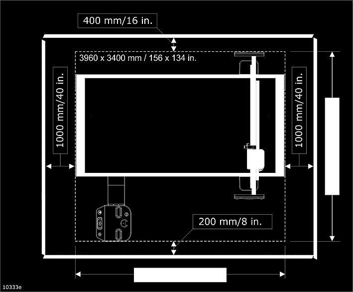
15 Illustration This illustration is included just to visualize the total size of the packed shipment..2 Room Layout Specification, Packaging Production Pay attention to effective work flow and proper material handling. Note: Vacuum Cleaner and Chiller are included if MultiCUT-HP is included in the installation. Symbol Explanation Vacuum Pump 15

16 Symbol Explanation Vacuum Cleaner Chiller Material work flow indication Attention area.3 System Layout, Packaging Production A typical installation is shown in the above illustration. A Single phase outlets for: B Pressurized air outlet. C Single phase outlets for Vacuum pump control. Three phase outlet for Vacuum pump. 16 Table PC Monitor


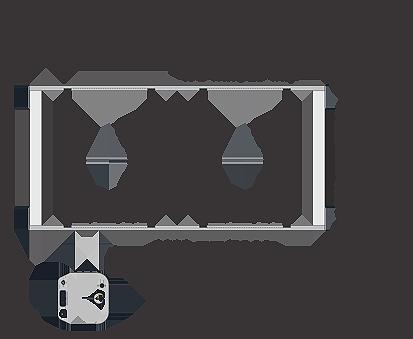
17 .4 Rotating Work Station Rotation o The work station top can be rotated 90. Shipment The Rotating Work Station will be shipped in the same box as the table frame, partly assembled. Alternative Position This is the standard Rotating Work Station position. 1


18 This is the alternative Rotating Work Station position..5 Table specification, Packaging Production 18


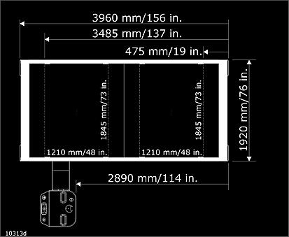
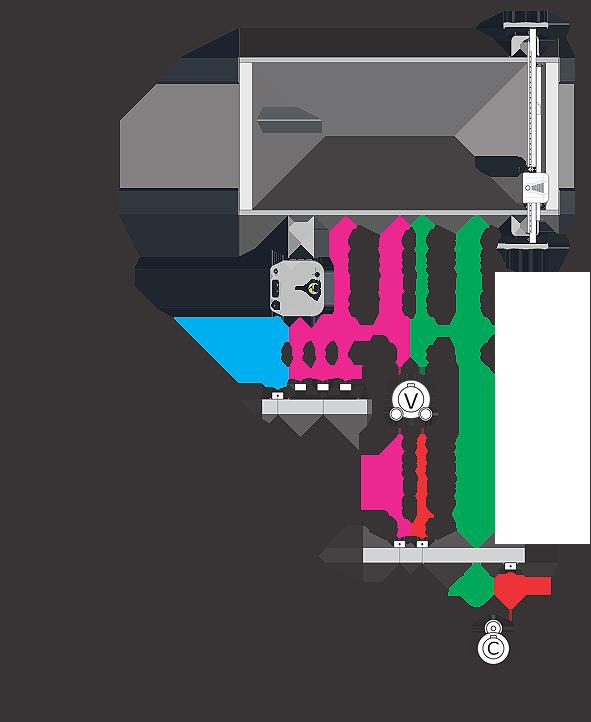
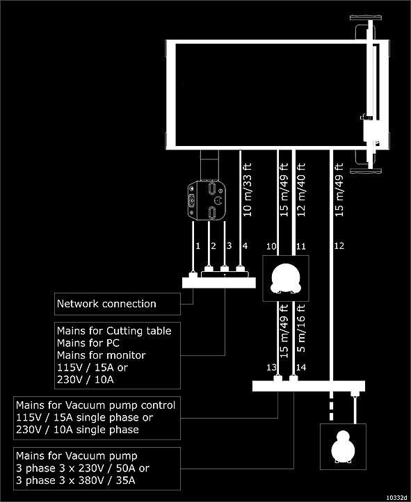
19 Foot print.6 Electrical Layout Specification, Packaging Production In the figure, you find alternatives for: Mains voltage / Fuse size. 19
20 Item No Description Plug to be supplied by customer 1 Network Connection. Customer responsible Yes 2 Mains for PC Yes 3 Mains for monitor Yes 4 Mains for Cutting table Yes 10 Vacuum Pump control No 11 Vacuum tube ø5 mm No 12 Air hose for Pressurised Air connector: 3/8 X 1/4 in. No 13 Mains for Vacuum Pump control relay Yes 14 Mains for Vacuum Pump Yes Mains Power Requirements Description Requirements Voltage: Frequency: Specified value +10%, 1-Phase 50/60 Hz +5%.. Direct Mains Connection, Guidelines A wall outlet for mains connection should be located in a position where it is visible from the equipment. Alternatively, a lockable Main Power ON/OFF switch can be installed. This to avoid main power accidentally being switched on while maintenance is carried out. All installations should be according to local regulations. The wall outlet shall meet the following requirements according to EN : Short circuit protection by fuses, max 16A. Insulation failure protection by automatic disconnection or alarm signal. It is the customer's responsibility to prepare the electrical installation according to local requirements. The conductors from the mains to the units should be terminated in 10 to 20 A ground make-first/ break-last type sockets. Each conductor should be 1.5 mm2 / inch2, and fuses (this applies for all line voltages) should protect live conductors. The Ground requirements of the system also apply to these conditions. Recommended line fuse sizes is found in the chapter: Cables and hoses. The cables shipped with the system do not have plugs, so that the customer can connect the type suitable for the power sockets. 20
21 .8 MultiCUT-HP, Packaging Production.8.1 Pressurized Air requirements For MultiCUT, it is important that the pressurized air level is constantly above bar measured locally at the outlet for the table. For details, see chapter: Compressed Air System..8.2 PC configuration for MultiCUT-HP A system with MultiCUT-HP requires two serial lines from the PC; one to the Cutting Table and one to the Router controller..8.3 Noise Level Description db(a) Vacuum cleaner Milling, A-weighted sound pressure level (Lpf) (Material dependant).9 Chiller for MultiCUT-HP.9.1 Requirements Environmental Requirements Description Requirements Temperature Operating: +10 C to +41 C / +50 F to +106 F.9.2 Installation 21


22 Dimensions Air input / output Assure free space 0.5 m / 20 in. on the air input side. Assure free space 1 m / 40 in. on the air output side. No chiller beneath cutting table.10 Compressed Air System.10.1 General The Compressed Air System consists of: Air Source. Industry Pressurized Air or dedicated Air Compressor. Connection Hose. Air Regulator Valve. The customer is required to provide the pressurized air source. 22
23 The customer is required to install the airline that leads from the air source to the table room and terminate the line with a quick connector (Air Source Outlet) Air Source Outlet An outlet for Compressed Air connection should be located in a position where it is visible from the equipment. Alternatively, a lockable Compressed Air ON/OFF switch can be installed. This to avoid that Compressed Air accidentally being switched on while maintenance is carried out. All installations should be according to Local Regulations Air Source Specification, Packaging Production Table: Capacity at bar: Description Requirements Running all tools, except MultiCUT-HP 30 l/min / 1 cfm. Running MultiCUT-HP 80 l/min / 3 cfm. Pressure 8 10 bar ( 8-10 kg/cm2, 8-10*105 Pa ). Constantly above bar measured locally at the outlet for the table. Moisture content Dew. Point - 10o C. Purity Particle content to be less than 5 µm in any dimension..11 Vacuum System.11.1 Introduction The Vacuum System consists of: Vacuum pump(s). Vacuum control unit. Has to be mounted on the wall close to the Vacuum pump. Connection Tube(s), diameter 5 mm. For detailed specification, see specific pump model. Pump location Due to its noise, the pump should be located in a separate location outside the table area. If a separate location is not available, using a sound insulating box should be considered. 23


24 Installation To achieve maximum vacuum hold-down effect, it is very important to avoid sharp corners on all tubes and connectors. Use 30 deg. bends. Pump cables are delivered without connectors for wall outlet. The Service Engineer will connect wires for vacuum control to the controller at the time of installation. No pump beneath Cutting table.11.2 Connection to table Vacuum tube to table connection, diameter 5 mm Tube assembly A vacuum tube kit included in the shipment contains necessary parts for connection to the pump: It is the customers responsibility if extra pipes or wiring is required. 24


25 Note: Extending the tube length beyond 15 m/49 ft will reduce the overall performance of the vacuum system. o For the vacuum tubing, avoid 90 corners Sound Insulating Box for Vacuum Pump An optional Sound Insulating Box for the vacuum pump is available:.12 Vacuum pump,.5 kw.12.1 Vacuum pump,.5 kw, introduction 25


 Hz Power (kw) SB010 SB010 3-phase")
26 Vacuum pump foot print Outlet dimension D: G 2.5 Weight: 114 kg/251 lbs. Environment Temperature for operation: +0 C to +30 C / +32 F to +90 F Relative humidity for operation: 30% to 80% Average noise level, exhaust connected to a pipeline: 4 db(a).12.2 Vacuum pump,.5 kw, electrical specification Electrical specification Pump model Mains Voltage (V) Hz Power (kw) SB010 SB010 3-phase 3-phase 230/ / Electrical connection Recommended fuse size/cable dimensions 26

.")
27 SB010 SB010 Voltage (V) Hz A Fuse (A) Cable dimensions /60 50/ mm mm 2 Note: The wall outlet shall meet the following requirements according to EN : Short circuit protection by fuses according to table in chapter 'Cables and hoses'. Insulation failure protection by automatic disconnection or alarm signal. It is the customer's responsibility to prepare the electrical installation according to local requirements. Pump control solution, Concept As illustrated below, two alternative vacuum control modes are available: Using a Soft Start unit. This is the default solution for this pump. Inverter control (E-Save). Soft Start unit E-Save Abbreviations Description M Ma Mc R Ov Vacuum Pump motor 3 - phase mains Single phase voltage for pump control Control relay ( ON / OFF ) Motor overload relay 2


28 Abbreviations Description E-Save E-Save control unit.12.3 E-save for Vacuum Pump Vacuum Pump control using a variable frequency drive (VFD) is available as an option System Layout 28 No Type Plug supplied by customer 1 Three phase mains for Vacuum pump Yes 2 Vacuum on/off control cable No 3 Vacuum sensor cable No 4 Motor cable No


29 Installation The Inverter should be mounted on the wall, close to the Vacuum pump. The Inverter is ready to run as soon as the Mains Power is switched on. Note: The inverter is generating noise, thus it is recommended to mount the Inverter together with the Vacuum pump in a separate room. To allow for heat dissipation, ensure free space around the Inverter. 29
30 8 8. Site Preparation Checklist Use this checklist to help verify your site's readiness and as a starting point for discussions with Esko personnel regarding your site preparations. # Check to be performed 1 Site Access Checks Can a semi/articulated lorry (1.5 ton) reach your site? Is a forklift with 2 meter/6.5 ft. fork extensions and pallet truck available to unload the crates from the truck? Do you have adequate indoor space to store the crates until installation? Is the size and spacing of the hallways and doorways on the route from unloading to the installation room adequate to bring all the crates through flat? Can the route from unloading to installation room hold the weight of the heaviest crate (including fork lift)? Is the floor level throughout the route (e.g. no stairways, no steps, etc.)? Is the route clear of any obstacles? (e.g. Does any equipment need to be moved?) Will there be 6-8 people available to assist lifting the table components to the final position on the first day of installation? Space for Kongsberg Table and Vacuum Pump Is the room large enough for the Kongsberg table s required space, also taking into account material handling? See chapter 'Footprint'. 10 Is the floor in the Kongsberg table room within specifications? See chapter 'Floor and Load Level'. 11 Does the room meet the environmental requirements? See chapter 'Environmental Requirements' Can the vacuum pump be placed within 15 meters of total pipe length to the table? Customer Supplied Services Are both three phase and single phase power available? See chapter 'Electrical Power Requirements'. 14 Can you connect the front-end PC to your network? 15 Is compressed air available, and within specifications? See chapter 'Compressed Air Requirements'. Notes 30 Yes No
31 9. Site Readiness Confirmation Form As a final documentation prior to installation, we need your confirmation that your site is ready for installation. To confirm that your site is ready, please send the completed and signed Site Readiness Confirmation form below to your order handler no later than 10 days prior to the installation of your table. Task Ready? All the requirements in the Site Access checklist have been met. All the requirements in the Space for Table and Vacuum Pump checklist have been met. Vacuum piping can be easily run between the pump and the table and if necessary a hole in the wall has been made. All required power, air and network cable has been installed at the location of the table and the vacuum pump. Software is available to generate die-lines. Materials are available for set up, testing & training. Operators are available for the end of week operator training as agreed upon with the Field Service Engineer. Please sign off that all the Site Readiness checks have been completed. Date: Name: Signature: 31 9