WIDE PART NUMBER OPERATING MANUAL HUK*B March, 2012
|
|
|
- Brittney Ray
- 6 years ago
- Views:
Transcription
1 WIDE HUK*B March, 2012 PART NUMBER OPERATING MANUAL
2
3 135950HUK*B Dear Customer, This product is part of the MOTORSCAN family of products. It is the result of many years of research and development. MOTORSCAN is glad to have you as a customer. Please contact one of our authorized distributors or our customer service department for any technical questions. ENGLISH
4 135950HUK*B Blank Page ENGLISH
5 135950HUK*B INDEX INDEX... i INTRODUCTION... 1 IMPORTANT INFORMATION ABOUT PERSONAL SAFETY... 2 IMPORTANT INFORMATION ABOUT PRODUCT SAFETY... 5 GENERAL INFORMATION... 5 INSTALLATION... 5 OPERATING INFORMATION... 5 CLEANING... 5 SYMBOLS... 6 PRODUCT DESCRIPTION GENERAL SPECIFICATIONS FRONT / CONNECTIONS VIEW REGULATING CONTRAST STANDARD ACCESSORIES OPTIONAL CONNECTING POWERING THE TOOL MOTORCYCLE IDENTIFICATION CONNECTING TO THE MOTORCYCLE USING A MASTER/SLAVE CABLE CONNECTING TO THE MOTORCYCLE USING UNIVERSAL CABLE CONNECTING TO THE MOTORCYCLE USING BMW SLAVE CABLE OPERATION SETUP MENU SCREENSHOT MANAGEMENT HELP FUNCTION DIAGNOSTIC FUNCTIONS SELECTING THE SEARCH MODE FOR SYSTEMS INSTALLED MANUAL SEARCH MANUAL SEARCH BY VEHICLE SELECTION MANUAL SEARCH BY ECU SELECTION AUTOMATIC SEARCH CONNECTION ECU MENU ECU DATA PARAMETERS READING STORED FAULTS ERASING STORED FAULTS DIAGNOSTIC PROCEDURES CONFIGURATIONS INDEX i ENGLISH
6 135950HUK*B HARLEY-DAVIDSON QUICK START PROCEDURE STEP 1: USING THE VEHICLES LIST STEP 2: CONNECTING THE HARLEY DAVIDSON CABLE TO THE SCANNER STEP 3: LOCATING THE MOTORCYCLE DIAGNOSTIC PORT STEP 4: CONNECTING THE SCANNER TO THE MOTORCYCLE STEP 5: STARTING DIAGNOSTIC WORK ON THE MOTORCYCLE /CAGIVA INJECTION ADJUSTMENT INITIAL STEPS ADJUSTING THE INJECTION SYSTEM USING THE / CAGIVA CABLE ORIGINAL VALUES RESET IDLING ADJUSTMENT REGULATION AT 10% REGULATION AT 25% - 50% - 75% REGULATION AT 100% APPENDIX SCREEN MENU SCREEN PROCEED EXIT SCREEN BINARY SELECTION SCREEN MESSAGE SCREEN MULTIPLE SELECTION SCREEN HELP SCREEN PARAMETERS TABLE SCREEN TYPES OF DIAGNOSTICS SERIAL COMMUNICATION BLINKING CODES DISPLAY CODES MANUAL PROCEDURE ENGLISH ii INDEX
7 135950HUK*B INTRODUCTION This manual is an integral part of the product. Read these instructions carefully before using the tool and keep them in a safe place. MOTORSCAN S.p.A. apologizes for any errors in the text. Brand names and products mentioned in the document are registered brands of the relevant owners. MOTORSCAN S.p.A. is not responsible to third parties for specific, collateral, accidental, direct, or indirect damage related to, or deriving from the product purchase and use. Copies of this document and technical information are available from an authorized distributor of MOTORSCAN S.p.A.. This document may not be copied or distributed, in part or its entirety, in any form or by any means, without prior written authorisation from MOTORSCAN S.p.A.. MOTORSCAN S.p.A. Str. Martinella, 28/A PARMA - Italy Tel Fax internationalsales@motorscan.com ass.tecnica@motorscan.com INTRODUCTION 1 ENGLISH
8 135950HUK*B IMPORTANT INFORMATION ABOUT PERSONAL SAFETY GENERAL SAFETY IN the WORKSHOP. DANGER OF SUFFOCATION GASOLINE ENGINES Exhaust gases from gasoline vehicles contain Carbon Monoxide, a colorless and odorless gas which, in case of inhalation, can cause serious physical injury or death. When working under a vehicle, be very careful. Some components of exhaust gases are heavier than air. Be careful also when working on LPG-propelled vehicles. DIESEL ENGINES The exhaust gas from a diesel engine has a composition that varies according to: type of engine, of induction, conditions of use, and fuel composition. The diesel exhaust includes gas (CO, CO 2, NO and HC) and particles (soot, sulphates and PAHs). The small carbon particles forming soot remain suspended in the air and can be breathed in. Small amounts of toxic components are also present. SAFETY MEASURES: - Always ensure good ventilation and breathing protection (especially when working under a vehicle. Always operate the exhaust fan system when working in confined spaces. DANGER OF CRUSHING Ensure that the vehicle is locked in place to prevent possible crushing. SAFETY MEASURES: - Make sure that the vehicle is unable to move by engaging the hand brake and locking the wheels. DANGER OF INJURY Whether engines are at a standstill or operating, there are moving parts (belts, etc.) that can injure hands and arms. Pay particular attention to electrically operated fans since these may unexpectedly start up even when the engine itself is off. SAFETY MEASURES: - Never place hands near moving parts when the engine is on. When working near electrically operated fans, let the engine cool first and then unplug the fan. - Keep the test instrument connection wires as far as possible away from moving parts of the engine. ENGLISH 2 INTRODUCTION
9 135950HUK*B DANGER OF BURNS Some of the components in engines (exhaust gas manifold, etc.) can become very hot, as can certain sensors. Remember to never touch these parts. SAFETY MEASURES: - Wear protective gloves. Never allow the test instrument connection wires to rest on or near hot parts. Never keep the engine running after the tests. DANGER OF FIRE OR EXPLOSION When work is being carried out on the fuel system (fuel pump, injectors and carburetor, etc.) there may be a risk of fire or explosion owing to the fuels used and/or the vapors that these products form. SAFETY MEASURES: - Disconnect the ignition system. Allow the engine to cool. - Do not use open flames or anything liable to produce sparks. - Do not smoke. - Collect any spilled fuel. - Operate exhaust fans in closed rooms. SOUND LEVEL When working near a vehicle, especially at high engine speed, noise levels can reach 90dB. Long term exposure to such noise sources can cause hearing damage. SAFETY MEASURES: - Wear hearing protection. INTRODUCTION 3 ENGLISH
10 135950HUK*B DANGEROUS VOLTAGE Work safely on vehicle electrical systems. Do not touch electrically live parts of engines. Be aware of the risk of shock from damaged connections. SAFETY MEASURES: - Only use the cables supplied with the test instrument. Make sure that the insulation is not damaged. - Do not touch live parts of the vehicle when testing with the engine running. - Only make test connections with suitable systems (test cables, specific adapter cables). DANGER OF ASFIXIATION If subjected to high temperatures (over 250 C or owing to fire outbreaks), exhaust gas hoses may release highly toxic gases. SAFETY MEASURES: - Immediately contact a physician if such gas is inhaled. - Use neoprene or PVC gloves to eliminate combustion residuals. - Fire residuals can be neutralized with a calcium hydroxide solution. This forms calcium fluoride which can be removed with water. DANGER OF CORROSION Acids can harm the skin if not protected. The residual condensate in gas sampling hoses and the condensate separator unit contains acids. Take great care when replacing the oxygen sensor (O 2 ) and the nitric oxide sensor (NO). They contain highly corrosive substances. Corrosive liquid may be spilled if a liquid crystal indicator is broken. This liquid should never be touched, inhaled or swallowed. SAFETY MEASURES: - In case of contact with the skin, immediately wash the affected area with water and contact a physician. - Immediately contact a physician if such products are inhaled or swallowed. ENGLISH 4 INTRODUCTION
11 135950HUK*B IMPORTANT INFORMATION ABOUT PRODUCT SAFETY This MOTORSCAN product provides a high level of protection against the risk of electric shock. The installer is responsible for connecting it to a correctly grounded electrical socket. Seek technical assistance before using an adapter or extension cable. These devices could interfere with the grounding circuit. Connection of the appliance to an incorrectly wired electrical outlet could result in electrocution. Comply with the following rules to protect against the risk of electrocution: - Only connect the instrument to electrical sockets delivering the correct voltage. Contact the electric utility if you are uncertain as to the outlet voltage. - If the instrument has other wires besides the power cable, these must be connected to their respective connectors before connecting the power cables to the electrical outlet. Disconnect the power cables from the sockets before removing other wires. Strictly comply with the following instructions when servicing: - Always replace fuses with others of equal value (see indications on the label or in this manual). - NEVER open the cover of the instrument: you could risk electrocution. This operation may only be carried out by a qualified technician and not before having disconnected the power supply cable. - Deviating from the instructions in this manual or attempting to repair the instrument carries the risk of electric shock. Pressing too hard on the display may damage the instrument. Please contact a service technician if the instrument fails to correctly function after following the operating instructions. Check that all installed spare parts have technical characteristics identical to those of the original parts. Other parts may not possess the same safety characteristics. Always contact qualified technical personnel if repairs are required. GENERAL INFORMATION INSTALLATION Never allow the instrument to be exposed to the sun for long periods of time or to allow it to stand near hot equipment (stoves, heaters, etc.): the maximum operating temperature is 40 C/105 F. Do not move the instrument from a hot place to a cold place and vice versa. The formation of condensation inside the device may damage the electronic circuits. Protect the instrument from rain or from excessive moisture. OPERATING INFORMATION To prevent contamination from toxic gas, it is advisable to use the instrument in a sufficiently ventilated place or to channel exhaust gases outdoors. Never pull on the instrument s cables. All connections should be made when the vehicle engine in question is off. Check that all cables are far away from hot parts (over 50 C/130F) or moving parts. Disconnect all engine connections before moving the vehicle in question. CLEANING When necessary, the outer surfaces of the instrument should be cleaned: never use cleaning products containing spirits, ammonia or gasoline. Only use neutral detergents and a soft, slightly moistened cloth. INTRODUCTION 5 ENGLISH
 CE CONFORMITY MARK It indicates compliance with the relevant European Union Directives. INFORMATION FOR THE USERS Pursuant to art.")
12 135950HUK*B SYMBOLS Symbols used in the DEVICE: ALTERNATING CURRENT GROUND PROTECTION CONSULT THE INSTRUCTION MANUAL RISK OF BURNS RISK OF ELECTROCUTION NEVER ATTEMPT TO REMOVE THE COVER (operation only to be carried out by qualified technicians) CE CONFORMITY MARK It indicates compliance with the relevant European Union Directives. INFORMATION FOR THE USERS Pursuant to art.13 of the Law Decree 25 July 2005, n.151 Implementation of directives 2002/95/CE, 2002/96/CE and 2003/108/CE on the reduction of the use of hazardous substances in the electrical and electronic equipment and waste disposal. The symbol of the bin with crossed lines on the equipment or on the packaging indicates that the product at the end of its useful life has to be collected separately from other waste. Disposal of the equipment at the end of its life is organized and managed by the manufacturer. The user wishing to dispose of the equipment should contact the manufacturer and comply with the system the latter has adopted for disposal of the equipment at the end of its life. Unauthorized disposal of the product by the owner may be penalized under the relevant laws in force in the country in question. ENGLISH 6 INTRODUCTION
13 135950HUK*B PRODUCT DESCRIPTION 1.1 GENERAL The is a compact, user-friendly scan tool. This state-of-the-art technology that allows diagnostics on all types of motorcycle communication protocols. The tool comes in a handy carrying case, to protect the tool and carry diagnostic cables. PRODUCT DESCRIPTION 7 ENGLISH
14 135950HUK*B 1.2 SPECIFICATIONS DIMENSIONS: 240 mm x 190 mm x 50 mm WEIGHT: 1 kg approx. (tool only, without accessories) POWER SUPPLY: POWER CONSUMPTION: 8 45 Vcc (typically 12 V from battery or vehicle diagnostic socket) or (15 V with power supply) V WORKING TEMPERATURE: C DISPLAY: KEYPAD: LED technology backlit graphic liquid crystal display, resolution 240 x 128 pixel 23 keys (alphanumeric, functions, arrows, ESC, ENTER) SHELL: Plastic handheld SERIAL INTERFACE: USB for HOST connection and software update INTERNAL MEMORY: 16 MB internal flash memory, updated via USB link PROTECTION KEY: Hardware with chip card to enable software updates. DIAGNOSTIC INTERFACE: DB15 proprietary (to connect diagnostic cables) COMMUNICATION PROTOCOLS: ISO (Keyword 2000) ISO ISO (SAE J Kbps PWM) (SAE J Kbps VPW) ISO (CAN BUS) PROPRIETARY PROTOCOLS ENGLISH 8 PRODUCT DESCRIPTION
15 135950HUK*B 1.3 FRONT / CONNECTIONS VIEW PRODUCT DESCRIPTION 9 ENGLISH
16 135950HUK*B 1.4 ADJUSTING CONTRAST The display on the scan tool can be adjusted by the operator by increasing or decreasing the contrast as required. To adjust contrast, proceed as follows: turn on the device by pressing one of the arrows underlined in the picture. Adjust the contrast by pressing the up arrow to increase and the down arrow to decrease. Press key 2 to confirm the selection. ENGLISH 10 PRODUCT DESCRIPTION


17 135950HUK*B 1.5 STANDARD ACCESSORIES Next to each motorcycle model in the Vehicles List you can find the part number for the cable required for a particular function. DESCRIPTION and PART N. PICTURE Carrying case Carrying case varies by region/ country of sale Scan tool Part number: SL5950ST CD with: - Operating instruction - Vehicles list Part number: 13CDSTRA5950 AC/DC 18W power supply Part number: 2303ASW18W Power cord Part number: 33CR-USA PRODUCT DESCRIPTION 11 ENGLISH


18 135950HUK*B DESCRIPTION and PART N. PICTURE Master Cable Part number: SL Required for the following cables: KAWASAKI 4 Pin SL KAWASAKI 8 Pin SL HONDA 4 Pin SL HONDA 3 Pin SL HONDA 2 Pin SL Pin SL Pin SL YAMAHA 3 Pin SL CAGIVA 10 Pin SL BMW SL HARLEY-DAVIDSON SL OBDII SL PACKARD SL APRILIA/DITECH SL KTM SL APRILIA/SAGEM SL PEUGEOT SL KYMCO SL KAWASAKI 4P/2007 SL BRP SL KAWASAKI REGUL. EINSP. SL BENELLI 6 Pin SL VDO 4 Pin SL DUCATI CAN 4 pin SL KAWASAKI 6 pin SL KAWASAKI 6 pin MY 2010 SL SYM 3 pin SL POLARIS 8 pin SL Battery power cable Part number: SL Universal Cable Applications: Aprilia 2, BMW, Cagiva 2, Harley Davidson 3, Honda, Kawasaki, Malaguti, Mondial, Suzuki, Yamaha. Part number: SL Except Marelli systems 3 Only Marelli systems ENGLISH 12 PRODUCT DESCRIPTION


19 135950HUK*B DESCRIPTION and PART N. PICTURE BMW Slave Cable Part number: SL Harley-Davidson Slave Cable Part number: SL OBDII Slave Cable Applications: Triumph Part number: SL Packard Slave Cable Applications: Aprilia 1, Bimota, Cagiva 1, Ducati, Gas Gas, Gilera, KVN Motor, Laverda, Malaguti1, Moto Guzzi, Moto Morini, MV Agusta, Piaggio, Sherco, Vespa, Voxan Part number: SL Only Marelli systems PRODUCT DESCRIPTION 13 ENGLISH


20 135950HUK*B 1.6 OPTIONAL The part number for the cable required for a particular function is next to each motorcycle model in the Vehicles List. Exact cables included vary by kit. Consult distributor. DESCRIPTION and PART N. PICTURE / CAGIVA Cable Part number: SL KAWASAKI 4 Pin Slave Cable Part number: SL KAWASAKI 8 Pin Slave Cable Part number: SL HONDA 4 Pin Slave Cable Part number: SL HONDA 3 Pin Slave Cable Applications: Honda with blinking code systems. Part number: SL WARNING: do not use on Aprilia/Ditech systems. ENGLISH 14 PRODUCT DESCRIPTION


21 135950HUK*B DESCRIPTION and PART N. PICTURE HONDA 2 Pin Slave Cable Part number: SL Pin Slave Cable Part number: SL Pin Slave Cable Part number: SL YAMAHA 3 Pin Slave Cable Part number: SL CAGIVA 10 Pin Slave Cable Part number: SL PRODUCT DESCRIPTION 15 ENGLISH


22 135950HUK*B DESCRIPTION and PART N. PICTURE APRILIA/DITECH Slave Cable Applications: Aprilia Ditech system. Part number: SL WARNING: do not use on Honda systems with blinking codes. KTM Slave Cable Part number: SL APRILIA/SAGEM Slave Cable Applications: Aprilia Sagem system. Part number: SL PEUGEOT Slave Cable Part number: SL KYMCO Slave Cable Part number: SL ENGLISH 16 PRODUCT DESCRIPTION


23 135950HUK*B DESCRIPTION and PART N. PICTURE KAWASAKI 4 Pin/2007 Slave Cable Part number: SL BRP Slave Cable Part number: SL KAWASAKI REG. INJ. Slave Cable Part number: SL BENELLI 6 Pin SLAVE CABLE Part number: SL VDO 4 Pin SLAVE CABLE Part number: SL PRODUCT DESCRIPTION 17 ENGLISH
24 135950HUK*B DESCRIPTION and PART N. PICTURE DUCATI CAN 4 Pin SLAVE CABLE Part number: SL KAWASAKI 6 Pin SLAVE CABLE Part number: SL KAWASAKI MY Pin SLAVE CABLE Part number: SL SYM 3 Pin SLAVE CABLE Part number: SL POLARIS 8 Pin SLAVE CABLE Part number: SL ENGLISH 18 PRODUCT DESCRIPTION
25 135950HUK*B CONNECTING WARNING! NEVER CONNECT THE THREE CLIPS (BLACK, RED AND YELLOW) ON THE SL CABLE TO THE BATTERY. WHEN STARTING A DIAGNOSTIC PROCEDURE ON A MOTORCYCLE, THE VCC CLAMPS ON THE SL CABLE MUST BE CONNECTED ONLY TO THE BATTERY ON THE MOTORCYCLE BEING TESTED. NEVER USE CABLES OTHER THAN THOSE SUPPLIED WITH THE TOOL. USE THE EXTERNAL POWER SUPPLY ONLY FOR UPDATING SOFTWARE OR FOR REFERING TO DATA STORED IN THE SCAN TOOL. DO NOT USE AN EXTERNAL POWER SUPPLY DURING DIAGNOSTICS. CONNECTING 19 ENGLISH

26 135950HUK*B 2.1 POWERING THE TOOL To turn the tool on, power it through the power supply, which comes with the tool, or through the battery cable SL (red clamp on the positive terminal and black clamp on the negative terminal.) Plug the female jack into the 12VDC port on the scan tool connection panel (see chapter VIEW OF CONNECTIONS ). WARNING! This start up mode must NOT be used for DIAGNOSTICS (see the menu, change Setup settings, software updating). dd/mm/yyyy hh/mm/ss 2.2 MOTORCYCLE IDENTIFICATION To start the diagnostic procedure, identify in the VEHICLES LIST the correct diagnostic cable for the motorcycle being worked on (see Vehicles List). Note: there may be several ways (with different cables) to connect to each bike. These are listed in the vehicles list. 499 = SL Packard slave cable 051 = SL battery alimentation cable M = SL Master cable ENGLISH 20 CONNECTING
27 135950HUK*B Follow the connection procedures below: SECTION Connecting to the motorcycle using UNIVERSAL cable (section 2.4). Connecting to the motorcycle using BMW SLAVE cable (section 2.5). VEHICLE LIST CODE 342 SL CABLES PART NUMBER M SL SL M SL SL SL /CAGIVA (section 5) SL SL Powering the tool (section 2.1). Connecting to the motorcycle using MASTER/SLAVE cables (section 2.3). 051 SL AD/DC 2303ASW18W M SL SL M SL SL M SL SL SL M SL SL SL M SL SL SL M SL SL M SL SL SL M SL SL M SL SL M SL SL M SL SL M SL SL SL M SL SL SL M SL SL SL M SL SL SL M SL SL SL M SL SL SL M SL SL M SL SL M SL SL M SL SL M SL SL M SL SL M SL SL M SL SL M SL SL SL M SL SL CONNECTING 21 ENGLISH
28 135950HUK*B 2.3 CONNECTING TO THE MOTORCYCLE USING A MASTER/SLAVE CABLE 1) Connect the MASTER SL cable to the tool. 2) Connect the 14 pin connector on the MASTER cable to the SLAVE cable indicated in the vehicles list. 3) If the SLAVE cable has a power jack, connect the SL cable also. 4) Connect the clamps to the battery terminals on the vehicle being tested (red clamp on the positive terminal and black clamp on the negative terminal). 5) Connect the other end of the SLAVE cable to the diagnostic socket on the motorcycle. 6) If the motorcycle is a, KAWASAKI or HARLEY-DAVIDSON: disconnect the anti-theft device/immobilizer, if installed. Turn the key ON, put the switch to RUN 7) Now make sure that the tool has switched on automatically, and that the tool start screen up is displayed. dd/mm/yyyy hh/mm/ss ENGLISH 22 CONNECTING
29 135950HUK*B 2.4 CONNECTING TO THE MOTORCYCLE USING THE UNIVERSAL CABLE If the correct cable is missing, or when it is explicitly indicated in the VEHICLE LIST, use the universal cable: - Connect the SL cable to the tool. - Connect the VCC clamps to the battery terminals on the vehicle being tested (red clamp on the positive terminal and black clamp on the negative terminal). - Ensure that the tool has switched on automatically, and that the tool start up screen is displayed. dd/mm/yyyy hh/mm/ss WARNING! WHEN USING THE SL UNIVERSAL CABLE, CONNECT TO THE DIAGNOSTIC SOCKET ONLY WHEN THE SOFTWARE TELLS YOU TO DO SO. CONNECTING 23 ENGLISH
30 135950HUK*B 2.5 CONNECTING TO THE MOTORCYCLE USING BMW SLAVE CABLE 1) Connect the MASTER SL cable to the tool. 2) Connect the 14 pins connector on the MASTER cable to the SLAVE cable SL ) If the SL cable is indicated in the vehicle list, connect it to the jack on the SLAVE cable and to the battery terminals on the vehicle being tested (red clamp on the positive terminal and black clamp on the negative terminal). 4) If the SL cable is required, connect the 3-pin end of the SL cable to the diagnostic socket on the vehicle. If the SL cable is not required, connect the BMW SLAVE 10-pin end. 5) Make sure that the tool switches on automatically and that the start up screen is displayed. dd/mm/yyyy hh/mm/ss WARNING! WHEN USING THE BMW CABLE SL TOGETHER WITH THE SL CABLE, CONNECT TO THE DIAGNOSTIC SOCKET ONLY WHEN INSTRUCTED TO DO SO. ENGLISH 24 CONNECTING
31 135950HUK*B OPERATION After connecting the tool to the diagnostic socket or to the power supply the following screen is displayed: dd/mm/yyyy hh/mm/ss The menu shown below appears after pressing any key on the scan tool. - MAIN MENU - Adiva Aprilia SETUP Menu This menu includes the list of all makes of motorcycles supported by the software version in the scan tool. Scroll down to find "SETUP MENU". See description in the relevant section. OPERATION 25 ENGLISH
32 135950HUK*B 3.1 SETUP MENU Select the SETUP function to bring up the following menu. - SETUP MENU - Language selection Screenshot management Videosoftware System of units Display SW release Update ME0149 Set time & date Display Barcode Hardware Test Main menu SETUP Menu LANGUAGE SELECTION: Function used to select language. SCREENSHOT MANAGEMENT: Managing saving screens( see section ) VIDEOSOFTWARE: only in case of selection of the video software (only 5615) SYSTEM OF UNITS: Function switches between the English/ Inch measurement system ( F, mi, mph, in Hg) and the standard international system ( C, km, km/h, mmhg). DISPLAY SW RELEASE: Function used to view software release installed in the tool. UPDATE ME0149: Optimization of ME0149 board functionality. SET TIME & DATE: Set time and date display. DISPLAY BARCODE: View the scanner s barcode. MAIN MENU: Return to main menu SCREENSHOT MANAGEMENT Anytime the F2 key is pressed a snapshot is taken of all items displayed in the screen. The pictures saved can be reviewed or deleted as follows: - SCREENSHOT MANAGEMENT - Display stored screenshot Erase screenshot buffer EXIT SETUP Menu If VIDEO PRINT 5615 is enabled on the scan tool, the screen shots saved can be also printed via a PC. ENGLISH 26 OPERATION
33 135950HUK*B 3.2 HELP FUNCTION Help screens (similar to those below) can be accessed by pushing the F1 key at any point in the software with the following exceptions: - Image display. - Graphic animation display. - HELP - Confirms item indicated Exits the list Moves item indicator up 1 line Moves item indicator down 1 line Moves item indicator up 6 lines Moves item indicator down 6 lines Press any key... OPERATION 27 ENGLISH
34 135950HUK*B 3.3 DIAGNOSTIC FUNCTIONS After selecting the make of the motorcycle to be tested, the diagnostic function selection menu appears. - KAWASAKI - Inj. blinking codes Injection EXIT KAWASAKI The menu being displayed is not always the same. It varies by the manufacturer selected in the "MAIN MENU". The following is a comprehensive list of diagnostic modules: IGNITION: INJECTION, display codes: INJECTION, blinking codes: INJECTION: IMMOBILIZER/ANTI-THEFT:: ABS: SERVICE: DASHBOARD: BODY COMPUTER: INJECTION REGULATION TRANSMISSION: EPT: PARKING: EPS: RDC: RADIO Ignition ECU diagnostics. Electronic injection ECU diagnostics, display codes mode. Electronic injection ECU diagnostics, blinking codes mode. Electronic injection ECU diagnostics. Immobilizer/ anti-theft system diagnostics. ABS system management ECU diagnostics. Resetting the service light. Dashboard ECU diagnostics. Body computer ECU diagnostics. Adjustment the injection timing through the electronic injection ECU. Automatic transmission ECU diagnostics. Diagnosing the ECU controlling the electronic accelerator (drive-by-wire) module Diagnosing the ECU controlling the parking brake for 3 wheels vehicles (i. e Piaggio MP3). Diagnosing the ECU controlling the electric steering wheels. Diagnosing the ECU controlling the tire pressure sensors. Diagnosing the ECU controlling the entertainment system ENGLISH 28 OPERATION
35 135950HUK*B 3.4 SELECTING THE SEARCH MODE FOR SYSTEMS INSTALLED After selecting the diagnostic module, select the mode for searching for systems installed on the motorcycle and for connecting to the motorcycle: - INJECTION - Manual search Automatic search EXIT KAWASAKI Injection MANUAL SEARCH: search for systems and connect by selecting motorcycle model or ECU. AUTOMATIC SEARCH: only for systems equipped with serial communication. If no system with serial communication is available for the selected make, the "automatic search" will be not work. Connect using the Manual Search mode MANUAL SEARCH The manual search by vehicle selection is the easiest operation for users lacking a thorough knowledge of the motorcycle being tested. The manual search by ECU selection is the quickest operation but the user should know beforehand which systems are installed on the vehicle, where the diagnostic connector is located, and what type it is. - MANUAL SEARCH - Vehicle selection ECU Selection EXIT KAWASAKI Injection OPERATION 29 ENGLISH
36 135950HUK*B MANUAL SEARCH BY VEHICLE SELECTION This function lists the models covered for the manufacturer selected, and supported by the current software version. - VEHICLE SELECTION - KX 450F (KX450E9F) KAWASAKI Injection Selecting the model of the motorcycle to work on brings up the following screens: - VEHICLE DATA - Model: KX 450F (KX450E9F) Diagnostic mode: Serial communication Cable type: Connector position: Attached to the factory ECU Connector image: Press <F5> KAWASAKI Injection KX 450F (KX450E9F) ENGLISH 30 OPERATION
37 135950HUK*B MODEL: Name of the selected motorcycle TYPE OF DIAGNOSTICS: Type of diagnostics supported by the system on the model selected. The types of diagnostics supported by the tool are the following: - Serial communication; - Blinking codes; - Display codes; - Manual procedure. TYPE OF CABLE: required diagnostic cable. CONNECTOR POSITION: indication of the position of the diagnostic connector. CONNECTOR IMAGE: picture of the connector (push F5) Screens for the selected system are displayed, indicating the status and connections, if any, of the diagnostic cable and of the key. - SEARCHING ECU - - SEARCHING ECU - Check antitheft disabled, if installed Check that engine switch is in RUN position and key on KAWASAKI Injection KX 450F (KX450E9F) KAWASAKI Injection KX 450F (KX450E9F) WARNING! WRONG CONNECTIONS CAN IRREPARABLY DAMAGE THE TOOL. For further information, please refer to the APPENDIX. OPERATION 31 ENGLISH
38 135950HUK*B If the ECU is equipped with serial communication, a connection is attempted. Connecting If the ECU search is successfully, a screen appears similar to the one below. - INJECTION - Connected ID received ECU recognised: Kawasaki DFI (4P/6P) KAWASAKI Injection KX 450F (KX450E9F) If the search fails, screens appear similar to the ones below. - SEARCHING ECU - - SEARCHING ECU - Cannot connect to ECU. Turn key off / KAWASAKI Injection KX 450F (KX450E9F) / KAWASAKI Injection KX 450F (KX450E9F) ENGLISH 32 OPERATION
39 135950HUK*B MANUAL SEARCH BY ECU SELECTION This function lists the ECUs for the manufacturer selected and supported by the current software version installed on the scanner. - ECU SELECTION - Kawasaki DFI (4P/6P) Kawasaki DFI (8P) EXIT KAWASAKI Injection After selecting the ECU for the motorcycle being tested, the selection is confirmed. - ECU SELECTION - ECU selected: Kawasaki DFI (4P/6P) PROCEED KAWASAKI Injection EXIT After selecting PROCEED, further instructions are displayed (see examples). - SEARCHING ECU - - SEARCHING ECU - Check antitheft disabled, if installed Check that engine switch is in RUN position and key on KAWASAKI Injection Kawasaki DFI (4P/6P) KAWASAKI Injection Kawasaki DFI (4P/6P) OPERATION 33 ENGLISH
40 135950HUK*B WARNING! WRONG CONNECTIONS CAN IRREPARABLY DAMAGE THE TOOL. If the ECU is equipped with serial communication, a connection is attempted. Connecting If the ECU search is successful, a screen appears similar to the one below. - INJECTION - Connected ID received XXXXXXXXX KAWASAKI Injection Kawasaki DFI (4P/6P) If the search is negative, error messages are displayed. ENGLISH 34 OPERATION
41 135950HUK*B AUTOMATIC SEARCH CONNECTION Use this function to connect automatically to the selected manufacturer if that manufacturer supports automatic connection. The user should be familiar with the position, type of diagnostic socket and connection instructions beforehand. WARNING! WRONG CONNECTIONS CAN IRREPARABLY DAMAGE THE TOOL. The following instructions are displayed. - SEARCHING ECU - - SEARCHING ECU - Check antitheft disabled, if installed Check that engine switch is in RUN position and key on KAWASAKI Injection KAWASAKI Injection After completing the above steps, connection to the ECU is attempted. Connecting OPERATION 35 ENGLISH
42 135950HUK*B If the automatic search is successful, a screen appears similar to the one: - SEARCHING ECU - Connected ID received ECU recognised: Kawasaki DFI (4P/6P) KAWASAKI Injection If the automatic search fails, error messages are displayed. - SEARCHING ECU - - SEARCHING ECU - Cannot connect to ECU. Turn key off / KAWASAKI Injection KX 450F (KX450E9F) / KAWASAKI Injection KX 450F (KX450E9F) ENGLISH 36 OPERATION
43 135950HUK*B 3.5 ECU MENU If the system search is successful, a menu appears similar to the one below. - KAWASAKI DFI (4P/6P) - ECU data Parameters Reading stored faults Erasing stored faults Diagnostic procedure EXIT KAWASAKI Injection KX 450F (KX450E9F) Kawasaki DFI (4P/6P) NOTE: Some items in the ECU menu might be not be shown. Not all manufacturers support all functions. ECU DATA: select to display the ECU data. PARAMETERS: select to display the parameters and live data supported by the ECU. READING STORED FAULTS: indicates the number of faults, the fault codes and relevant descriptions (if available). Will also indicate possible causes, if available. ERASING STORED FAULTS: resets all stored faults. DIAGNOSTIC PROCEDURE: test the components controlled by the ECU. CONFIGURATIONS: change the settings of some of the components controlled by the ECU. EXIT: press to stop communication. OPERATION 37 ENGLISH
44 135950HUK*B ECU DATA By selecting "ECU data" from the "ECU MENU", a screen appears similar to the one below. - ECU DATA - - ECU DATA - Model year: 2) 'xx Specification: 2) xxxxxxxxxxxxx ECU part #: xxxxxxxxxxxxx Vehicle model: 1) xxxxxxxxxxxxx Model year: 1) 'xx Specification: 1) xxxxxxxxxxxxx Vehicle model: 2) xxxxxxxxxxxxx / KAWASAKI Injection KX 450F (KX450E9F) Kawasaki DFI (4P/6P) / KAWASAKI Injection KX 450F (KX450E9F) Kawasaki DFI (4P/6P) PARAMETERS By selecting Parameters from the "ECU MENU", the list of parameters supported is displayed. - PARAMETERS - Ignition switch Throttle angle KAWASAKI Injection KX 450F (KX450E9F) Kawasaki DFI (4P/6P) Using the key select a list of parameters (6 max. simultaneously). Push F5 to display the selected parameters. ENGLISH 38 OPERATION
45 135950HUK*B After confirming the selection, a table (see below) displays the data in real time. Ignition switch Throttle angle - PARAMETERS - ON x,xxu Use the arrows ( ) to move the cursor to scroll long texts. Push the F5 key to display live data on further parameters supported by the ECU READING STORED FAULTS Select Reading stored faults from the "ECU MENU", to read faults stored in the ECU. If no faults are stored, the following screen (or something similar) appears. - STORED FAULTS - No fault Stored KAWASAKI Injection KX 450F (KX450E9F) Kawasaki DFI (4P/6P) Press to return to the ECU menu. OPERATION 39 ENGLISH
46 135950HUK*B If faults are present in the ECU, a screen appears similar to the one below, indicating the number of saved DTCs. - STORED FAULTS - Stored Diagnostic Fault Codes x KAWASAKI Injection KX 450F (KX450E9F) Kawasaki DFI (4P/6P) Press to display the list including code and description of faults stored. - STORED FAULTS - P Injector 1 P Gasoline pump relay locked P Throttle sensor xxxxxx - xxxxxxxx KAWASAKI Injection KX 450F (KX450E9F) Kawasaki DFI (4P/6P) Selecting an item from the above list brings up a screen for the specific fault, with additional information, as in the following image. DESCRIPTION: Injector # 1 - DTC: P KAWASAKI Injection KX 450F (KX450E9F) Kawasaki DFI (4P/6P) ENGLISH 40 OPERATION
47 135950HUK*B ERASING STORED FAULTS Selecting "Erasing stored faults" in the "ECU MENU" deletes faults stored in the ECU. Before deleting fault codes, confirm by pressing PROCEED. - DELETING FAULTS - This deletes faults from ECU memory PROCEED KAWASAKI Injection KX 450F (KX450E9F) Kawasaki DFI (4P/6P) EXIT Once the procedure has been completed, the status is displayed. - DELETING FAULTS - Faults deleted! KAWASAKI Injection KX 450F (KX450E9F) Kawasaki DFI (4P/6P) OPERATION 41 ENGLISH
48 135950HUK*B DIAGNOSTIC PROCEDURES Select "Diagnostic procedures" in the "ECU MENU", to display the list of tests of components controlled by the ECU and supported by the scan tool. - DIAGNOSTIC PROCEDURES - Fuel pump Ignition coil 1 EXIT KAWASAKI Injection KX 450F (KX450E9F) Kawasaki DFI (4P/6P) Selecting a diagnostic procedure in the menu starts the test in question. - DIAGNOSTIC PROCEDURES - Fuel pump Test in progress KAWASAKI Injection KX 450F (KX450E9F) Kawasaki DFI (4P/6P) Press to stop the test. When the diagnostic procedure is complete, the result of the test is displayed. ENGLISH 42 OPERATION
49 135950HUK*B CONFIGURATIONS Select "Configurations" in the "ECU MENU" to display the list of setup and adjustment operations controlled by the ECU and supported by the scan tool. - CONFIGURATIONS - TPS zero setting CO calibration EXIT APRILIA Injection MARELLI IAW 15 P Selecting an item from the list starts the process. For some setup operations, confirm using CONTINUE. The following screen shows an example of a supported setup function. - CONFIGURATIONS - Trimmer- value 2 or to vary to confirm to cancel APRILIA Injection MARELLI IAW 15 P When the setup or adjustment procedure is complete, the result is displayed. OPERATION 43 ENGLISH
50 135950HUK*B Blank Page ENGLISH 44 OPERATION
 In the Harley Davidson section, search for the motorcycle in the MODEL column. 2) Verify the model year and the systems covered by the scanner.")
51 135950HUK*B HARLEY-DAVIDSON QUICK START PROC. Follow these instructions to use the scan tool on a Harley-Davidson motorcycle. 4.1 STEP 1: USING OF THE VEHICLES LIST 1) In the Harley Davidson section, search for the motorcycle in the MODEL column. 2) Verify the model year and the systems covered by the scanner. Note: Some systems are optional and might not be installed on some motorcycles (such as an IMMOBILIZER/anti-theft system, or ABS).). 3) Select the applicable diagnostic cable (CABLES column). All Harley-Davidson motorcycles have the same cable SL The "M" suffix (480+M) indicates that the cable Master SL is also required together with the other one. Harley Davidson Section STEP 2: CONNECTING THE HARLEY DAVIDSON CABLE TO THE SCANNER Connect the Master SL cable to the ECU port of the tool. Connect the 14 pins connector on the MASTER cable to the SLAVE cable SL indicated in the vehicles list. SL SL HARLEY-DAVIDSON QUICK START PROC. 45 ENGLISH
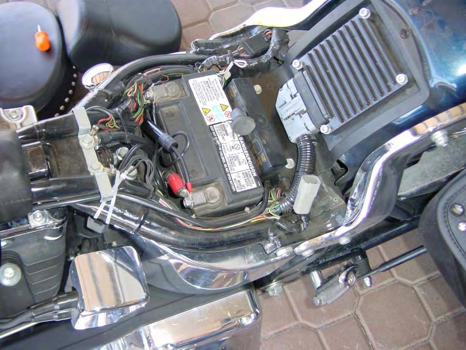
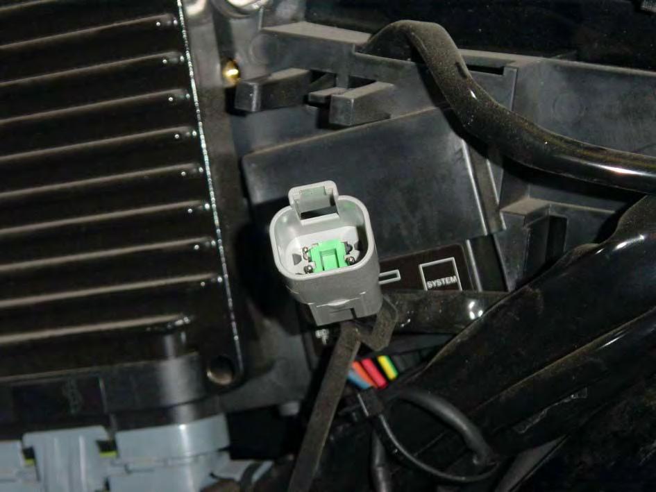
 With the Sportster series, remove the seat and the left side panel, use the pictures below to identify the 4 pin diagnostic connector, remove the cap and go to STEP 4.")
52 135950HUK*B 4.3 STEP 3: LOCATING THE MOTORCYCLE DIAGNOSTIC PORT 1) Identify the Harley-Davidson motorcycle series: Sportster, Dyna, Softail, VRSC or Touring. 2) With the Sportster series, remove the seat and the left side panel, use the pictures below to identify the 4 pin diagnostic connector, remove the cap and go to STEP 4. ENGLISH 46 HARLEY-DAVIDSON QUICK START PROC.


53 135950HUK*B 3) With the Dyna series, remove the left side panel and, use the pictures below to identify the 4 pin diagnostic connector. Remove the cap and go to STEP 4. HARLEY-DAVIDSON QUICK START PROC. 47 ENGLISH

54 135950HUK*B 4) With the Softail series, remove the seat, using the pictures below to identify the 4 pin diagnostic connector. Remove the cap and go to STEP 4. ENGLISH 48 HARLEY-DAVIDSON QUICK START PROC.

55 135950HUK*B HARLEY-DAVIDSON QUICK START PROC. 49 ENGLISH


56 135950HUK*B 5) For VRSC series motorcycles, remove the left side panel on the steering column. Use the pictures below to, identify the 4 pin diagnostic connector, remove the cap and jump to STEP 4. ENGLISH 50 HARLEY-DAVIDSON QUICK START PROC.
57 135950HUK*B 6) With the Touring series, remove the right hand case and the right hand panel. Use the diagrams below to identify the 4 pin diagnostic connector, and remove the cap. HARLEY-DAVIDSON QUICK START PROC. 51 ENGLISH

58 135950HUK*B ENGLISH 52 HARLEY-DAVIDSON QUICK START PROC.
 Connect the SL010480 Harley-Davidson cable to")
 If the motorcycle has an immobilizer security system, turn it off.")
 If the lock-set is installed, turn the key to the \"UNLOCK\" position and then turn the")
59 135950HUK*B 4.4 STEP 4: CONNECTING THE SCANNER TO THE MOTORCYCLE 1) Connect the SL Harley-Davidson cable to the motorcycle diagnostic socket. 2) If the motorcycle has an immobilizer security system, turn it off. 3) If the lock-set is not installed, turn the key into "IGN" (or IGNITION) position and go to step 5. 4) If the lock-set is installed, turn the key to the "UNLOCK" position and then turn the lock-set to "IGN" (or IGNITION) position. 5) Set the RUN/OFF (engine) switch to "RUN" position. LOCK SET (TIPO 1) LOCK SET (TIPO 2) RUN/OFF SWITCH HARLEY-DAVIDSON QUICK START PROC. 53 ENGLISH
60 135950HUK*B 4.5 STEP 5: STARTING DIAGNOSTIC WORK ON THE MOTORCYCLE 1) Check that the scan tool is turned on. 2) Press any key and select "Harley-Davidson" in the MAIN MENU. 3) Select the applicable system for the motorcycle, as defined in the SYSTEM column in the VEHICLES LIST (STEP 1). 4) Select "Automatic search" and wait for connection to the motorcycle ECU. 5) Press the ENTER key ( ) and select the applicable diagnostic function. dd/mm/yyyy hh/mm/ss - MAIN MENU - GILERA HARLEY-DAVIDSON HONDA SEARCHING ECU - - INJECTION - Ignition Manual search Injection Automatic search Immobilizer EXIT HARLEY-DAVIDSON HARLEY-DAVIDSON Injection - SEARCHING ECU - - SEARCHING ECU - Check antitheft disabled, if installed Check that engine switch is in RUN position and key on HARLEY-DAVIDSON Injection HARLEY-DAVIDSON Injection - INJECTION - Connected ID received ECU recognised: DELPHI ECM Connecting HARLEY-DAVIDSON Injection ENGLISH 54 HARLEY-DAVIDSON QUICK START PROC.
61 135950HUK*B /CAGIVA INJECTION ADJUSTMENT Follow these instructions to use the optional cable SL to adjust the injection system on and CAGIVA motorcycles, where the ECU has this capability. WARNING! PLEASE READ THE NEXT SET OF INSTRUCTIONS IN DETAIL. THESE DESCRIBE HOW TO USE THE /CAGIVA CABLE PROPERLY. ANY IMPROPER USE OF THIS CABLE CAN CAUSE IRREPARABLE DAMAGE TO THE SCAN TOOL. 5.1 INITIAL STEPS 1) Connect the SL to the scan tool diagnostic socket. 2) Connect the SL cable to the SL cable. 3) Connect the battery clamps to the battery terminals on the motorcycle being tested (red clamp on the positive terminal and black clamp on the negative terminal). 4) Verify that the scan tool is switched on. 5) Wait for the initial screen to appear and press the DIAG key. 6) In the MAIN MENU select "CAGIVA" or depending on the motorcycle you want to test. 7) When the systems selection menu appears, select Injection Adjustment, Manual search and afterwards Vehicle selection. 8) Select the vehicle model and connect the scan tool to the injection system adjustment socket on the motorcycle as described in screens 7.1, 7.2 e 7.3 below. 9) Push the ENTER key ( ) and only now connect the SL cable to the diagnostic socket on the motorcycle, as described in the screen of point 8. 10) At this point you can access the main ECU menu. Select Configurations to view the supported adjustments, as described in the next sections. dd/mm/yyyy hh/mm/ss - MAIN MENU - SHERCO SYM Inj. Display Codes Injection ABS Transmission INJECTION - Manual search EXIT /CAGIVA INJECTION ADJUSTMENT 55 ENGLISH
62 135950HUK*B - MANUAL SEARCH- - VEHICLE SELECTION - Vehicle selection ECU selection GSX-R EXIT GSX-R1000 Limited Edition VEHICLE DATA - Model: Diagnostic mode: Serial communication Cable type: Connector position: Under the seat Connector image: Press <F5> SEARCHING ECU - - SEARCHING ECU - Start with key off and antitheft off. If installed Connect SL cable to the injection Regulation socket on motorcycle (REG) - - CONFIGURATIONS - Configurations EXIT Original values reset Idling adjustment Regulation at 10% Regulation at 25% Regulation at 50% Regulation at 75% Regulation at 75% EXIT (REG) (REG) ENGLISH 56 /CAGIVA INJECTION ADJUSTMENT
63 135950HUK*B 5.2 ADJUSTING THE INJECTION SYSTEM USING THE / CAGIVA CABLE The operations described in this section must be carried out only by a qualified technician. This function adjusts the motorcycle injection timing. The smaller openings of the throttle valve should be adjusted first, as the idling and 10% affect the bigger openings (50%, 75%, 100%). The adjustments are in real time. If you use the arrow keys to enrich or reduce the fuel, the fuel values, as well as the injection times, are adjusted while the engine is on. The only exception is the idling adjustment with all cylinders selected. Here you operate in real time only on one single cylinder. After confirming the adjustment value by pressing the ENTER key, all cylinders are adjusted in sequence to the same value as the first cylinder. The motorcycle ECU does not provide the current injection time adjustment values. To make adjustments easier, the unit stores the most recent values set using the adjustment cable. When working on a new motorcycle, where the current injection time configuration is unknown, go to Original values reset. If you intend to work on more than one motorcycle, it is a good idea to create a personal data base of the last values set on each motorcycle. The following sections show the screens displayed during injection adjustments. These screens indicate which key has which function in the injection adjustment process. Use these keys in sequence to adjust the injection system: increase the value by 1% increase the value by 10% decrease the value by 10% decrease the value by 1% to store the set value. to restore the original setting. /CAGIVA INJECTION ADJUSTMENT 57 ENGLISH
64 135950HUK*B ORIGINAL VALUES RESET This function resets the ECU to its original factory settings. This is necessary when working on a particular motorcycle for the first time. After selecting Original values reset the following screens appear in sequence. - CONFIGURATIONS - - CONFIGURATIONS - This function reset to original ECU Setting PROCEED EXIT (REG) Turn key on and set engine switch to RUN (REG) - CONFIGURATIONS - - CONFIGURATIONS - Turn key off Data storage in process (REG) ENGLISH 58 /CAGIVA INJECTION ADJUSTMENT
65 135950HUK*B IDLING ADJUSTMENT This function adjusts the idling injection. It is possible to adjust the idling on each cylinder, and on all cylinders at the same time. Setting a value between +10% - +40% is preferable. During the storage phase the change in cylinder noise can be heard, depending on the adjustment value percentage. After selecting Idling adjustment the following screens appear in sequence. - CONFIGURATIONS - - CONFIGURATIONS - This function regulate the idling injection PROCEED EXIT (REG) Turn key on and start engine / (REG) - CONFIGURATIONS - - CONFIGURATIONS - Warm up engine and regulate idling to lowest possible value / (REG) With engine running, select in next Screen one single cylinder or all Cylindersfor regulation / (REG) - CONFIGURATIONS - - CONFIGURATIONS - Cylinder 1 Cylinder 2 Cylinder 3 Cylinder 4 All (REG) In the next screen modify the regulation Value using the arrows key. to confirm entry (REG) - CONFIGURATIONS - - CONFIGURATIONS - Adjustment value 0% or to increase or to reduce Data storage in process to confirm. to cancel (REG) (REG) After making the adjustments Stop engine and turn key off. /CAGIVA INJECTION ADJUSTMENT 59 ENGLISH
66 135950HUK*B REGULATION AT 10% This function adjusts the injection opening to 10% of the throttle valve. This function requires the engine to be warmed up. Make sure 93 C (200 F) is not reached, as this will cause the ECU will try to compensate the overheating and the set adjustments will be incorrect. After selecting Regulation at 10% the following screens appear in sequence. - CONFIGURATIONS - - CONFIGURATIONS - This function regulates opening Injection to 10% of the throttle valve PROCEED EXIT (REG) Turn key on and start engine / (REG) - CONFIGURATIONS - - CONFIGURATIONS - Warm engine to temperature of 82 C (180 F) 87 C(190 F) not higher Than 93 C(200 F) / (REG) Without motorcycle in gear set target Rpm value to increase and keep constant / (REG) - CONFIGURATIONS - - CONFIGURATIONS - Adjustment value 0% In the next screen modify the regulation or to increase Value using the arrows key. to confirm or to reduce Entry to confirm. to cancel (REG) (REG) - CONFIGURATIONS - - CONFIGURATIONS - Data storage in process Stop engine and turn key off (REG) (REG) After making the adjustments Stop engine and turn key off. Verify that the idling adjustment has not been negatively affected. If so repeat the idling Idling adjustment. ENGLISH 60 /CAGIVA INJECTION ADJUSTMENT
67 135950HUK*B REGULATION AT 25% - 50% - 75% These functions adjust the injection opening to 25%, 50%, or 75% of the throttle valve. Warm up the engine. Make sure 93 C (200 F) is not reached, as this will cause the ECU will try to compensate the overheating and whatever adjustments made will not be saved. After selecting Regulation at 10% the following screens appear in sequence. Once you reach the values which achieve the best engine response at a quick opening of the throttle valve to 25% (see screens 1.3 and 1.4 ), use the same procedure for the points (50% and 75%). When looking for the optimal value, it is advisable to adjust to +/- 20% of the desired value. After selecting Regulation at 25%, Regulation at 50%, Regulation at 75% the following screens appear in sequence. Only the percentage value of the throttle valve will change. - CONFIGURATIONS - - CONFIGURATIONS - This function regulates opening Injection to 25% of the throttle valve PROCEED EXIT (REG) Turn key on and start engine / (REG) - CONFIGURATIONS - - CONFIGURATIONS - Warm engine to temperature of 82 C (180 F) 87 C(190 F) not higher Than 93 C(200 F) / (REG) Set gear to ist speed, set the engine Rpm at 5000RPM and hold constant / (REG) - CONFIGURATIONS - - CONFIGURATIONS - Open throttle quickly to 25% and check Engine response / (REG) In the next screen modify the regulation Value using the arrows key. to confirm Entry (REG) /CAGIVA INJECTION ADJUSTMENT 61 ENGLISH
68 135950HUK*B - CONFIGURATIONS - - CONFIGURATIONS - Adjustment value 0% or to increase or to reduce Data storage in process to confirm. to cancel (REG) - CONFIGURATIONS (REG) Stop engine and turn key off (REG) After making the adjustments Stop engine and turn key off. ENGLISH 62 /CAGIVA INJECTION ADJUSTMENT
69 135950HUK*B REGULATION AT 100% This function adjusts the injection opening at 100% of the throttle valve. To find the optimal value it is advisable make adjustments of +/- 20% of the desired value. Road tests with a complete opening of the throttle valve are required. It is possible that the ideal value is negative. After selecting Regulation at 100% the following screens will appear in sequence. - CONFIGURATIONS - - CONFIGURATIONS - This function regulates opening Injection to 100% of the throttle valve PROCEED EXIT (REG) Turn key on and set engine switch to RUN (REG) - CONFIGURATIONS - - CONFIGURATIONS - Adjustment value 0% In the next screen modify the regulation or to increase Value using the arrows key. to confirm or to reduce entry to confirm. to cancel (REG) (REG) - CONFIGURATIONS - - CONFIGURATIONS - Data storage in process Stop engine and turn key off (REG) (REG) After having executed the adjustments Stop engine and turn key off. /CAGIVA INJECTION ADJUSTMENT 63 ENGLISH
70 135950HUK*B Blank Page ENGLISH 64 /CAGIVA INJECTION ADJUSTMENT
71 135950HUK*B APPENDIX 6.1 SCREEN T This section describes the main types of screens displayed when using the diagnostic software. The screens shown in the following sections are examples and may be subject to modification MENU SCREEN Selection arrow - MAIN MENU - Adiva Aprilia SETUP Menu Selection arrow direction The MENU screen is for selection of an item from a list. The functions of navigation keys are described below: : return to the previous screen. : select the item indicated. : : : : move the selection arrow up 1 item. move the selection arrow down 1 item. move the selection arrow up 6 items (only if the menu has more than 6 items). move the selection arrow down 6 items (only if the menu has more than 6 items). APPENDIX 65 ENGLISH
72 135950HUK*B PROCEED EXIT SCREEN - CONFIGURATION - Highlighted item This function regulate the idling injection PROCEED EXIT (REG) Use the PROCEED EXIT command to continue by selecting PROCEED or to stop by selecting EXIT. The functions of navigation keys are described below: : confirm the highlighted item. : move the selection to the left. : move the selection to the right BINARY SELECTION SCREEN - SEARCHING ECU - Select the type of diagnostic socket of the motorcycle 6 PINS 4 PINS XXXXXXXX Xxxxxxxxxxxx Xxxxxxxxxxxxxxxx In the BINARY SELECTION screen select one of two options. The functions of navigation keys are: : return to the previous screen. : confirm the option that has been selected. : move the selection arrow up. : move the selection arrow down. ENGLISH 66 APPENDIX
73 135950HUK*B MESSAGE SCREEN Indicates the presence of additional invisible text lines - CONFIGURATION - Refer to the next picture. Read on the Motorcycle display the position of the Dash located to the left of the c00 message / XXXXXXXX Xxxxxxxxxxxx Current page/total pages indicator. Xxxxxxxxxxxxxxxx The MESSAGE screen displays a message. The current page/total pages indicator is displayed only if there are several MESSAGE screens in sequence. The functions of navigation keys are described below: : return to the previous screen or the previous sequence of messages. : display the next message or screen. : : : move the message screen up one line (only if the message has more than 6 lines). move the message screen down one line (only if the message contains more than 6 lines). return to the previous message (only in case of messages in sequence). APPENDIX 67 ENGLISH
74 135950HUK*B MULTIPLE SELECTION SCREEN Selection arrow - PARAMETER - Ignition switch Throttle angle Intake pressure Intake air temperature Atmospheric pressure XXXXXXXX Xxxxxxxxxxxx Xxxxxxxxxxxxxxxx Selection arrow direction The MULTIPLE SELECTION screen allows one or more options to be selected from a list. The functions of navigation keys are described below: : return to the previous screen. : add an item to the multiple selection. : : : : F5 move the selection arrow up 1 item. move the selection arrow down 1 item. move the selection arrow up 6 items (only if the menu has more than 6 items). move the selection arrow down 6 items (only if the menu has more than 6 items). confirm the multiple selection ENGLISH 68 APPENDIX
75 135950HUK*B HELP SCREEN - HELP - Confirms item indicated Exits the list Moves item indicator up 1 line Moves item indicator down 1 line Moves item indicator up 6 lines Moves item indicator down 6 lines Press any key... The HELP screen provides information on the functions of keys displayed in the lower right hand part of the screen. Push any key to go to the following help screen (if any) or to return to the screen where help was requested. APPENDIX 69 ENGLISH
76 135950HUK*B PARAMETERS TABLE SCREEN - PARAMETERS - Ignition switch Throttle angle. Water temperature. Intake air temperature Engine rpm Battery voltage ON X,XXU XX.X C XX.X C XRPM XX.XV The "PARAMETERS TABLE" screen displays live data from the ECU. To scroll the long texts, press the arrow key ( ) once. The functions of navigation keys are described below: : return to the parameters selection menu. : : : : F5 move the enabling cursor up 1 line. move the enabling cursor down 1 line. move the enabling cursor from the right column to the left column. move the enabling cursor from the left column to the right column. display the table of the following parameters supported by the ECU (6 simultaneously). ENGLISH 70 APPENDIX
77 135950HUK*B 6.2 TYPES OF DIAGNOSTICS SERIAL COMMUNICATION Serial communication is the most advanced diagnostics mode. A communication handshake is established automatically between the scan tool and the ECU. This type of diagnostic capability also allows the display of live data from the ECU and may support the adjustment of certain functions BLINKING CODES Blinking codes are a simple diagnostic mode for identifying fault codes stored in the ECU. Fault codes are indicated by a series of long and short blinks from the malfunction indicator lamp (LED), as described below. When the malfunction indicator lamp blinks, long blinks denote tens. Short blinks denote units. For instance, in case of error 15, the malfunction indicator gives one long blink (1 ten) and 5 short blinks (5 units). In the event of more than one fault code, the ECU stores all fault codes. These are then displayed in sequence. The code sequence is repeated until the autodiagnostics mode is activated. If no fault is present, the malfunction indication lamp does not light up. For instance, if two faults occur, 12 and then 15, maintenance codes are displayed as follows. The autodiagnostics function activation mode is explained by messages displayed on the instrument panel of the motorcycle being tested. APPENDIX 71 ENGLISH
78 135950HUK*B DISPLAY CODES Display codes identify fault codes stored in the ECU. Fault codes are indicated by a number or by an alphanumeric code shown on the display of the motorcycle dashboard. If more than one fault is present, the ECU stores all fault codes, which are then displayed in sequence. Codes are repeated in sequence until the autodiagnostics mode is activated. The autodiagnostics function activation mode is explained by messages displayed on the instrument panel of the motorcycle being tested MANUAL PROCEDURE Some diagnostics functions can be activated with manual procedures and are described by the scanner on a case by case basis. ENGLISH 72 APPENDIX
79

80 FOR SALES AND TECHNICAL SUPPORT IN ENGLISH-SPEAKING COUNTRIES, PLEASE CONTACT: STRATEGIC TOOLS & EQUIPMENT COMPANY TEL: FAX: MOTORSCAN S.p.A. Str. Martinella, 28/A PARMA Italia Tel
64C Amplification Block. Instruction Manual
 64C Amplification Block Instruction Manual Caution: All rights reserved. Quidel Corporation reserves the right to modify this manual at any time without notice. Any part of the manual shall not be duplicated,
Table of contents. 1. Introduction
 2 Year Warranty Table of contents 1. Introduction 1-1. Transportation 1-2. Preliminary steps 1-3. Initial setup 1-4. Important safety instructions 1-5. Maintenance, service and faults 2. Operation 2.1
Manual. AGRETO Hydraulic Scale AGRETO electronics GmbH
 Manual AGRETO Hydraulic Scale 22.04.2014 AGRETO electronics GmbH Content 1 Introduction... 3 2 Scope of Delivery... 3 3 Intended Use... 3 4 Security... 4 4.1 Safety Instructions for the Buyer... 4 4.2
2200-Lb. Semi-Electric Stacker OWNER S MANUAL
 2200-Lb. Semi-Electric Stacker OWNER S MANUAL WARNING: Read carefully and understand all ASSEMBLY AND OPERATION INSTRUCTIONS before operating. Failure to follow the safety rules and other basic safety
INDEX. 1 Introduction. 2 Software installation. 3 Open the program. 4 General parameters. 5 Tuning
 SET UP MANUAL INDEX 1 Introduction 2 Software installation 3 Open the program 4 General parameters 5 Tuning 2 1 Introduction Here below the instruction to use the FLYJET software. 1.1 Software features
INSTRUCTION MANUAL. Voice Command Quadcopter with 2MP Camera
 Ver. 4 INSTRUCTI MANUAL Voice Command Quadcopter with 2MP Camera SKY2913 CAUTI Please retain these instructions for future reference. Ensure that the drone is correctly assembled to prevent any injuries
Operation Manual INCUBATOR2 Dual Dry Block Incubator
 Operation Manual INCUBATOR2 Dual Dry Block Incubator Hygiena USA info@hygiena.com 805-388-8007 / 888-494-4362 Hygiena International enquiries@hygiena.net +44 0 1923 818821 Foreword Thank you for purchasing
OPERATOR S MANUAL. LINKIT Series LKS300/LKS450 Portable Conveyor. InterQuip USA LLC interquip.net DISTRIBUTED BY: OPERATOR S MANUAL
 OPERATOR S MANUAL LINKIT Series LKS300/LKS450 Portable Conveyor DISTRIBUTED BY: InterQuip USA LLC 203.322.2600 interquip.net 1 IMPORTANT Read, understand and obey these safety rules and operating instructions
EGT-AF08 USER GUIDE WHEEL WEIGHING SYSTEMS WITH VARIOUS PLATFORMS
 EGT-AF08 USER GUIDE WHEEL WEIGHING SYSTEMS WITH VARIOUS PLATFORMS Revision 1.00 Last update 01/02/2013 Page intentionally left blank. EGT-AF01 USER GUIDE Table of contents 1 INTRODUCTION... 5 2 TECHNICAL
Operation Manual. Dual Temperature Digital Dry Block Incubator. Catalog No. INCUBATOR Rev C. April 2016
 Operation Manual Dual Temperature Digital Dry Block Incubator Catalog No. INCUBATOR2 Rev C. April 2016-1 - Thank you for your purchase. This manual contains operation information for the Dual Temperature
FLARING MACHINE MAINTENANCE & INSTRUCTIONS MANUAL. Allswage UK. Roebuck Street, West Bromwich, B70 6RB
 FLARING MACHINE MAINTENANCE & INSTRUCTIONS MANUAL A. WARRANTY AND RESPONSIBILITY Warranty: It's the supplier's responsibility to guarantee the conformity of the product, assuring that it's manufactured
VBC Manual MManualManual. Installation and user manual for the VBC
 VBC400-600 Manual MManualManual Installation and user manual for the VBC400-600 Before You Begin Read these instructions before installing or operating this product. Note: This installation should be made
Gelovit 200 en English
 Gelovit 200 en English Translation of the original instructions BA 85 981 / 02 334.00001... en Gelovit 200 This unit documentation is part of the unit and must be enclosed when selling or passing on the
HOBO Plug Load Logger (UX ) Manual
 Manual") HOBO Plug Load Logger (UX120-018) Manual The HOBO Plug Load logger is designed to monitor energy consumption of AC-powered plug in loads. This compact device can be used as a power meter with its built-in
HOBO Plug Load Logger (UX120-018) Manual The HOBO Plug Load logger is designed to monitor energy consumption of AC-powered plug in loads. This compact device can be used as a power meter with its built-in
Installation & Calibration
 Installation & Calibration Type to enter text ED4-SR SkidWeigh Plus System Lift Truck Onboard Weighing System - Active Session Recordings (Recycling Industry Application) Version: V1.02 General Installation
Instruction Manual Dräger MSI EM200-s
 Dräger MSI GmbH Rohrstraße 32 58093 Hagen Tel.: +49-2331 / 9584-0 Fax: +49-2331 / 9584-29 e-mail: info@draeger-msi.de D 950; Edition 2011-01-01 Content 1. Reference notes Page 3 1.1 Approvals 1.2 Information
OPERATION MANUAL. A220 Arc Welding Machine. Serial Number: Where Purchase: Date of purchased:
 OPERATION MANUAL A220 Arc Welding Machine Serial Number: Where Purchase: Date of purchased: CONTENT 1.Safety... 2 2. Summary... 4 3. Electrical principle drawing... 5 4. Specifications... 6 5. Operation
User s Manual. KSV NIMA Dip Coaters
 User s Manual KSV NIMA Dip Coaters DipCoater Revision 1.3 Table of Contents 1 INTRODUCTION -------------------------------------------------------------------------------------------- 1 2 KSV NIMA INTERFACE
INSTRUCTION MANUAL FOR WIRE WELDING MACHINE
 INSTRUCTION MANUAL FOR WIRE WELDING MACHINE IMPORTANT: BEFORE STARTING THE EQUIPMENT, READ THE CONTENTS OF THIS MANUAL, WHICH MUST BE STORED IN A PLACE FAMILIAR TO ALL USERS FOR THE ENTIRE OPERATIVE LIFE-SPAN
FORM: OM-874D MIC-4 Interface Control
 OWNER S MANUAL FORM: OM-874D 093 324 MIC-4 Interface Control 2011 01 1. Safety Symbol Definitions DANGER! Indicates a hazardous situation which, if not avoided, will result in death or serious injury.
Welding & Fabrication Tools Mini VaR Tool Kit
 With Volta Tools You Can Never Go Wrong! Fast and simple belt installation. Unique and versatile design - compact, rugged and easy-to-use. Designed for both shop and field use. Light-weight construction.
BANKNOTE READER BT-11
 English Jofemar BANKNOTE READER BT-11 User s Manual MNP85ENV00 Rev.02 (2014-01-07) Page 1 of 20 Note WARNING Read these instructions carefully before using the appliance: This symbol means there are more
DEIF A/S. Description of options. Option H5, CAN bus based engine interface comm. Automatic Gen-set Controller. Description of option
 Description of options Option H5, CAN bus based engine interface comm. Automatic Gen-set Controller 4189340375C SW version 2.1X.X Description of option Functional description DEIF A/S Parameter list Modbus
User Manual. Precision Balances XSR models
 User Manual XSR models Overview balances with S weighing platform 4 3 5 2 3 1 6 7 2 8 8 10 9 10 9 Legend balances with S weighing platform 1 MagicCube Draft Shield 6 MagicCube Draft Shield side door 2
Installation & Calibration Manual
 Installation & Calibration Manual ED3/ED4-LTL-WD CubeFreight (ED3/ED4-LTL-WDBT CubeFreight system with Bluetooth module) Lift Truck Onboard Dimensioning & Check Weighing Initiated by Barcode Scanner CubeFreight
Stay Safe Around Electricity and Natural Gas Teacher s Guide
 Stay Safe Around Electricity and Natural Gas Teacher s Guide INTRODUCTION The Stay Safe Around Electricity and Natural Gas activity booklet can be used as a follow-up to a utility presentation or as a
2004 MAXIMA AND QUEST (WITH 5 SPEED A/T ONLY); MIL ON WITH DTC P0171 / P0174 / P1273 / P1283 A/F SENSOR / FUEL INJECTION SYSTEM
; MIL ON WITH DTC P0171 / P0174 / P1273 / P1283 A/F SENSOR / FUEL INJECTION SYSTEM") Classification: Reference: Date: EC04-007a NTB04-027a March 24, 2004 2004 MAXIMA AND QUEST (WITH 5 SPEED A/T ONLY); MIL ON WITH DTC P0171 / P0174 / P1273 / P1283 A/F SENSOR / FUEL INJECTION SYSTEM This
Classification: Reference: Date: EC04-007a NTB04-027a March 24, 2004 2004 MAXIMA AND QUEST (WITH 5 SPEED A/T ONLY); MIL ON WITH DTC P0171 / P0174 / P1273 / P1283 A/F SENSOR / FUEL INJECTION SYSTEM This
HydroLink Watering System with Snake Tubing Installation, Operation & Maintenance Manual
 HydroLink Watering System with Snake Tubing Installation, Operation & Maintenance Manual This manual provides detailed instructions for safely installing, operating and maintaining the HydroLink Watering
Best Selection for Your Business. Electronic Pricing Scale. User s Manual. (Model: TP-31)
") Best Selection for Your Business Electronic Pricing Scale User s Manual (Model: TP-31) CATALOG 1. Foreword... 2 1.1. Introductions... 2 1.2. Main functions and features... 2 1.3. Specification... 2 1.4.
Best Selection for Your Business Electronic Pricing Scale User s Manual (Model: TP-31) CATALOG 1. Foreword... 2 1.1. Introductions... 2 1.2. Main functions and features... 2 1.3. Specification... 2 1.4.
PLEASE READ THIS MANUAL CAREFULLY BEFORE OPERATION
 Hand Motion Shaker MPA-3 Operation Manual PLEASE READ THIS MANUAL CAREFULLY BEFORE OPERATION Hagavish st. Israel 58817 Tel: 972 3 5595252, Fax: 972 3 5594529 mrc@mrclab.com MRC.12.16 Contents I. SUMMARY...
Please read these instructions before use and retain for future reference
 User Manual DPF-830 Please read these instructions before use and retain for future reference 1 CONTENTS 1. Safety Precautions ------------------------------------------------------------------------------3
NEVER REMOVE THE SAFETY GUARDS
 Page 1 of 5 Name Recommended Use Designed for cutting stumps up to 200 mm above ground and 120 mm below ground. Maximum Stump diameter 300 mm. NOT suitable for stumps surrounded by rocks, stones, concrete
SUSPENSION MODULE. Installation and user manual per module. Easy Lift series "DxxxxxxXxxx" or "ExxxxxxXxxx"
 SUSPENSION MODULE By Installation and user manual per module Easy Lift series "DxxxxxxXxxx" or "ExxxxxxXxxx" Dear Customer, thank you for choosing Land Rover Passion and for purchasing the suspension module
 CHECK, Table of contents 1. Introduction --------------------------------------------------------------------------------------2 1.1 What Is OBD? ---------------------------------------------------------------------------------2
Manual. (979) T101 RFC Set. T105 HyRunnerBasic. T109 HySpeedster.
 T101 RFC Set. T105 HyRunnerBasic. T109 HySpeedster.") Manual T101 RFC Set T105 HyRunnerBasic T107 HyRunner T109 HySpeedster www.fuelcellstore.com sales@fuelcellstore.com (979) 703-1925 Contents 04 04 05 06 08 11 12 14 16 19 23 24 25 26 28 29 Your Duties as
Manual T101 RFC Set T105 HyRunnerBasic T107 HyRunner T109 HySpeedster www.fuelcellstore.com sales@fuelcellstore.com (979) 703-1925 Contents 04 04 05 06 08 11 12 14 16 19 23 24 25 26 28 29 Your Duties as
ProColor Flat Panels. User Manual. 151 NE State Hwy 300, Ste A Belfair, WA
 ProColor Flat Panels User Manual 151 NE State Hwy 300, Ste A Belfair, WA 98528 360.464.2119 www.boxlight.com Contents Important safety Instructions ---------------------------------------------------------
This product has been tested and certified to conform to ASTM F2456, Youth Resistant Firearms Container.
 Owner s Manual This product has been tested and certified to conform to ASTM F2456, Youth Resistant Firearms Container. RAPiD SAFE 2600KP Item No. 98177 Fold out for mounting template This device complies
FAST POWER FACTOR REGULATOR. Computer-14df - xx - 144a INSTRUCTION MANUAL ( M / 00A ) (c) CIRCUTOR S.A.
 (c) CIRCUTOR S.A.") FAST POWER FACTOR REGULATOR Computer-14df - xx - 144a INSTRUCTION MANUAL ( M 981 611 / 00A ) (c) CIRCUTOR S.A. -------- POWER FACTOR REGULATOR COMPUTER- 14f --------- Page 2 POWER FACTOR REGULATOR COMPUTER-
FAST POWER FACTOR REGULATOR Computer-14df - xx - 144a INSTRUCTION MANUAL ( M 981 611 / 00A ) (c) CIRCUTOR S.A. -------- POWER FACTOR REGULATOR COMPUTER- 14f --------- Page 2 POWER FACTOR REGULATOR COMPUTER-
iloader LTS On-Board Scale for Front Loader (User Manual)
") 1 iloader LTS On-Board Scale for Front Loader (User Manual) Istanbul, 2018 2 Contents 1. User Interface Summary...3 2. Installation and Wiring...5 3. Calibration (Commissioning)...8 4. Material and Customer
1 iloader LTS On-Board Scale for Front Loader (User Manual) Istanbul, 2018 2 Contents 1. User Interface Summary...3 2. Installation and Wiring...5 3. Calibration (Commissioning)...8 4. Material and Customer
booster EX2 / EX3 Operating Manual Extrusion Welder Weldy AG Galileo-Strasse 10 CH-6056 Kaegiswil / Switzerland TECHSPANGROUP
 booster EX2 / EX3 Extrusion Welder Operating Manual Weldy AG Galileo-Strasse 10 CH-6056 Kaegiswil / Switzerland TECHSPANGROUP Australia: Tel. 1-800 148 791 Fax. 1-800 148 799 www.weldy.com.au New Zealand:
Keep your head out of the gas. When you are welding, air extractor should be used to prevent inhalation of gas.
 Installation Instructions for 81542 TIG Welder 200 Page 1 Safety Caution! In the process of welding or cutting, there will be possibility of injury, so please take personal protection into consideration
X30 System Components
 X30 System Components X30 Monitor - Monitor is 12.1 inches - LINUX operating system not windows - Can-based communication. No serial ports - New part number 3132-10 LED Light Bar Battery Status LED Light
Industrial flue gas probes. Instruction manual
 Industrial flue gas probes Instruction manual 2 1 Contents 1 Contents 1 Contents... 3 2 Safety and the environment... 4 2.1. About this document... 4 2.2. Ensure safety... 4 2.3. Protecting the environment...
MMA ARC/TIG WELDING MACHINE INTIG
 MMA ARC/TIG WELDING MACHINE INTIG 250 INSTRUCTION MANUAL M/s WARPPP ENGINEERS PVT. LTD. B 1005, 10 TH FLOOR, WESTERN EDGEE II, NEAR METRO MALL, OFF.WESTERN EXPRESS HIGHWAY, BORIVALI (E), MUMBAI 4000 066.
AHP WELDS USER MANUAL
 AHP WELDS USER MANUAL Alpha-TIG200X (version III) Contents 1. Safety... 2 2. About your AlphaTig 200X... 3 3. Parameters... 4 4. Panel Index... 5 5. Setup Instructions... 6 6. Operating Instructions...
PMA 31-G. English. Printed: Doc-Nr: PUB / / 000 / 00
 PMA 31-G English 1 Information about the documentation 1.1 About this documentation Read this documentation before initial operation or use. This is a prerequisite for safe, trouble-free handling and
Instruction Manual HT 24 BM-D2400 Homogenizer
 Instruction Manual HT 24 BM-D2400 Homogenizer Foreword Thank you for purchasing a HT 24 Homogenizer. This manual contains instructions for the proper operation and care of this instrument. Please read
USER MANUAL AVLDITEST XDS 1000 EXPERIENCED DIAGNOSTIC SOLUTION FUTURE SOLUTIONS FOR TODAY
 USER MANUAL AVLDITEST XDS 1000 EXPERIENCED DIAGNOSTIC SOLUTION Ident number: AT7669E Revision: 07 Issue: 2018-06 Software version: 2018-02 Data may change without notice. All data valid at the time of
SUSPENSION MODULE. Installation and user manual per module. Easy Lift series "FxxxxxxXxxx" or above
 SUSPENSION MODULE by Installation and user manual per module Easy Lift series "FxxxxxxXxxx" or above Dear Customer, thank you for choosing Land Rover Passion and for purchasing the suspension module Easy
Hydro-wind Education Kit ASSEMBLY GUIDE
 Hydro-wind Education Kit ASSEMBLY GUIDE Battery operation instructions: Model No.: FCJJ-56 Warning To avoid the risk of property damage, serious injury or death: This kit should only be used by persons
DEIF A/S. Description of options. Option H5 Serial communication (CAN bus) Multi-line 2 version 2. Description of option. Functional description
 Multi-line 2 version 2. Description of option. Functional description") Description of options Option H5 Serial communication (CAN bus) Multi-line 2 version 2 4189340359E SW version 2.4X.X Description of option Functional description DEIF A/S Parameter list Modbus communication
Description of options Option H5 Serial communication (CAN bus) Multi-line 2 version 2 4189340359E SW version 2.4X.X Description of option Functional description DEIF A/S Parameter list Modbus communication
ENel Sp. z o. o. - WROCŁAW DESIGN AND MANUFACTURE OF POWER ELECTRONIC DEVICES INVERTER WELDING MACHINE ENEL250A USER MANUAL DEALER:
 ENel Sp. z o. o. - WROCŁAW DESIGN AND MANUFACTURE OF POWER ELECTRONIC DEVICES INVERTER WELDING MACHINE ENEL250A USER MANUAL DEALER: . INTRODUCTION This manual contains information that will allow to take
Moving money forward UV MG
 Moving money forward T This manual contains important information on safety measures and operational features, please read it carefully before operating your currency counter and keep it for future reference.
NA-3N, NA-3NF, NA-3S, NA-3SF & NA-4 Troubleshooting Guide
 NA-3N, NA-3NF, NA-3S, NA-3SF & NA-4 Troubleshooting Guide IM278-TS September, 2006 Safety Depends on You Lincoln arc welding and cutting equipment is designed and built with safety in mind. However, your
Z; MIL ON WITH DTC P0106 STORED
 Classification: Reference: Date: EC12-013 NTB12-053 June 22, 2012 2010 2012 370Z; MIL ON WITH DTC P0106 STORED APPLIED VEHICLE: All 2010-2012 370Z Coupe and Roadster (Z34/HZ34) IF YOU CONFIRM: An APPLIED
TF20 Tray Feeder. Instruction Manual. for JEDEC and IEC Standard Trays
 for JEDEC and IEC Standard Trays Instruction Manual 096-0243-003 Data I/O assumes no liability for errors, or for any incidental, consequential, indirect, or special damages, including, without limitation,
Operation and Maintenance Manual
 M0088349-01 (en-us) February 2018 Operation and Maintenance Manual Product Link PL042 and PLE702 Systems PL7 1-UP (Machine Control & Guidance Products) SAFETY.CAT.COM Important Safety Information i06558969
User Manual. XK315A1 water proof series Weighing Indicators. Applications: Electronic platform scale, weighing scale, etc.
 User Manual XK315A1 water proof series Weighing Indicators Applications: Electronic platform scale, weighing scale, etc. 1 Introductions 1.1 Safety precautions WARNING! Don t use XK315A1 series indicators
July P Wide Format Stacker User Guide
 July 2009 701P49768 Wide Format Stacker User Guide 2009 Xerox Corporation. All rights reserved. Xerox and the sphere of connectivity design are trademarks of Xerox Corporation in the United States and/or
2012 G25; MIL ON WITH DTC P0101 AND/OR P010B
 Classification: Reference: Date: EC13-019 ITB13-054 December 13, 2013 2012 G25; MIL ON WITH DTC P0101 AND/OR P010B APPLIED VEHICLES: 2012 G25 Sedan (V36) APPLIED ENGINE: VQ25HR IF YOU CONFIRM: MIL ON with
Into the future with ContiSys. Systematic multi-brand vehicle diagnostics.
 www.vdo.com Into the future with ContiSys. Systematic multi-brand vehicle diagnostics. Shape your future business today. With our products and services in vehicle electronics and mechatronics we are acting
Summary Report for Individual Task H-1538 Operate ATLAS Rough Terrain Forklift With a Load Status: Approved
 Report Date: 22 May 2014 Summary Report for Individual Task 551-88H-1538 Operate ATLAS Rough Terrain Forklift With a Load Status: Approved Distribution Restriction: Approved for public release; distribution
Always there to help you. Register your product and get support at HTL2101A. Question? Contact Philips.
 Always there to help you Register your product and get support at www.philips.com/support Question? Contact Philips HTL2101A Quick start guide Safety and important notice Read and understand all instructions
POWER PINNER BENCH HAND WELDER 7250 OPERATOR S MANUAL
 POWER PINNER BENCH HAND WELDER 7250 OPERATOR S MANUAL Copyright: November 20, 2018 Revised: Serial No. Gripnail Corporation An Employee Owned Company 97 Dexter Road East Providence, Rhode Island 02914-2045
LEISTER WELDMAX Mini-Hand Extruder
 GB OPERATING INSTRUCTIONS LEISTER WELDMAX Mini-Hand Extruder Please read operating instructions carefully before use and keep for further reference. Application Welding of thermoplastic materials made
DJ Switch 10F V2 ORDERCODE 50365
 DJ Switch 10F V2 ORDERCODE 5035 Congratulations! You have bought a great, innovative product from Showtec. The Showtec DJ Switch brings excitement to any venue. Whether you want simple plug-&-play action
Manual Rotary Heat Sealers. Type: F108TX. List of content : Introduction 2. General description 3. Application 4. Safety precautions 5
 Manual Rotary Heat Sealers Type: F108TX List of content : Page: Introduction 2 General description 3 Application 4 Safety precautions 5 Transport and storage 6 Installation 7 First Set-up 8 Connection
Winzer Corporation 1 Revision: 4.0
 Table of Content Section 1: Getting Started... 2 1.1 Overview... 2 Section 2: Installation Overview... 3 2.1 Install CD / Start.exe... 3 2.2 Welcome Screen... 4 2.3 Device Selection... 4 2.4 Auto or Industrial...
RENA XPS-3000 Base. User Guide. SC2000 Media Transport System
 SC2000 Media Transport System User Guide Please refer to your PS-2000 User Guide for information on the print system that may be attached to this base. NOTE: The SC2000 is also available in a stand-alone
Operating Manual. Professional Weighing Equipment. TB Series intelligent weighing machine. Touch Color Screen HIGH RESOLUTION BALANCE
 Professional Weighing Equipment Operating Manual TB Series intelligent weighing machine Touch Color Screen HIGH RESOLUTION BALANCE 1 Introduction What you should know about these Operating Instructions:
DeskDECT Feature Phone
 DeskDECT Feature Phone Please read this manual carefully before using your DeskDECT. 1. 2. 2.1 2.2 INTRODUCTION -------------------------------------------------- GETTING STARTED ---------------------------------------------
Galaxy 300 and Galaxy 300i
 Galaxy 300 and Galaxy 300i 10-40 kva 380/400/415 V Operation 07/2016 www.schneider-electric.com Legal Information The Schneider Electric brand and any registered trademarks of Schneider Electric Industries
User manual AGRETO HFM II AGRETO electronics GmbH
 User manual AGRETO HFM II 08.02.2014 AGRETO electronics GmbH Table of contents 1 Introduction... 3 2 Scope of delivery... 3 3 Intended use... 4 4 Security... 5 4.1 Safety instructions for the buyer...
Directions for use Spare parts list PDE
 Directions for use Spare parts list PDE 0 man. auto 5 0 sec t IN OUT 15 Stand-by Pilot Plasma-gas error Shield-gas error 0 0 TestPlasma Shield PDE TABLE OF CONTENTS Technical data... 1 Personel safety...
Instruction Manual Pocket scale
 KERN & Sohn GmbH Ziegelei 1 D-72336 Balingen email: info@kern-sohn.com Tel: +49-[0]7433-9933-0 Fax: +49-[0]7433-9933-149 Internet: www.kern-sohn.com Instruction Manual Pocket scale KERN TAB Version 1.1
Instruction Manual ODY-1765
 INSPIRING IMAGINATION Instruction Manual ODY-1765 We hope you enjoy your purchase of the Stealth NX-2 Drone and use this Instruction Manual to get your drone to take off! Included Contents 1. Stealth NX-2
EN REAL TIME RECEIVER AND RW INSTALLATION AND USE
 07-0106-EN REAL TIME RECEIVER AND RW INSTALLATION AND USE GENERAL POINTS The Intratone 07-0106-EN (EEN-REC4) receiver has two modes: - Real time: connected to a control unit and/or GPRS/3G module. - RW,
Wireless Freezer Manual Installation Guide
 Wireless Freezer Manual Installation Guide Doc # 152-11103-01 Revision DRAFT May 2009 Copyrights Copyright 2008 by. All rights reserved. The information in this document is subject to change without notice.
RL SERIES. Two Stage Light Oil Burners FIRING RATES LIGHT OIL
 The RL series of burners covers a firing range from 154 to 2700 kw, and it has been designed for use in low or medium temperature hot water boilers, hot air or steam boilers, diathermic oil boilers. Operation
RAPiD VEHICLE SAFE. Owner s Manual. Instructional videos for Hornady Security products are available at hornady.com. With patented RFID technology.
 Owner s Manual RAPiD VEHICLE SAFE With patented RFID technology. Item No. 98210 Instructional videos for Hornady Security products are available at hornady.com. READ THIS FIRST Warning: NEVER store a loaded
Universal Robots for 2200 Series Conveyors
 Universal Robots for 2200 Series Conveyors Service Manual UR3 UR5 UR10 For other service manuals visit our website at: www.dornerconveyors.com/manuals-literature 851-897 Rev. A Record Conveyor Serial Number
CN Series P.N , Software rev. T 8, Revision A1- July 2014
 Adam Equipment CN Series P.N. 7.00.6.6.0199, Software rev. T 8, Revision A1- July 2014 Adam Equipment 2014 Adam Equipment 2014 CONTENTS 1.0 INTRODUCTION... 2 2.0 SPECIFICATIONS... 3 2.1 DISPLAY AND KEYPAD...
User Guide. ARE H9 Full-ISO Pocket Reader
 Revision 008 User Guide ARE H9 Full-ISO Pocket Reader ---------------------------------------------------------------1/36--------------------------------------------------------------- 1 INTRODUCTION 4
INSTRUCTION MANUAL WARNING: BEFORE USING THE MACHINE READ THE INSTRUCTION MANUAL CAREFULLY!
 INSTRUCTION MANUAL WARNING: BEFORE USING THE MACHINE READ THE INSTRUCTION MANUAL CAREFULLY! SECTION 1 : PRODUCT AND COMPANY IDENTIFICATION PRODUCT NAME : SYNONYMS : PRODUCT CODES : Weldability ARC140i
New Measurement Engineering for Heating Fitters and Technicians
 testo 330-1 New Measurement Engineering for Heating Fitters and Technicians Increased safety and more convenience NEW! C hpa O 2 CO NO P Increased safety and convenience in flue gas analysis The new flue
Daker DK kva. Parallel installation quick start. Part. LE08927AA-09/15-01 GF
 Daker DK 4.5-10 kva Parallel installation quick start Part. LE08927AA-09/15-01 GF Daker DK 4.5-10 kva UK ENGLISH 3 2 Daker DK 4.5-10 kva Index Introduction 2 1 Important Safety Instructions 2 2 Parallel
Technical Service Bulletin
 14645 Keswick Street * Van Nuys, CA 91405 Technical Service Bulletin The following service bulletin contains information essential to the proper diagnosis and repair of any P0420 / P0430 codes present
Leister WELDPLAST S4 / WELDPLAST EC4 Hand extruder
 GB OPERATING INSTRUCTIONS Leister WELDPLAST S4 / WELDPLAST EC4 Hand extruder Please read operating instructions carefully before use and keep for further reference. APPLICATION Welding PE and PP thermoplastics
Operating instructions. METTLER TOLEDO MultiRange Application software IND690-FormXP.
 Operating instructions METTLER TOLEDO MultiRange Application software IND690-FormXP www.mt.com/support Congratulations on choosing the quality and precision of METTLER TOLEDO. Proper use according to these
VENTO WIFI DRONE WITH LIVE STREAMING CAMERA
 VENTO WIFI DRONE WITH LIVE STREAMING CAMERA INSTRUCTION MANUAL THANK YOU. Thank you for your purchase of Protocol s Vento Wifi Drone with Live Streaming Camera. You are about to experience the best of
The Shocking Truth About Electrical & Natural Gas Safety Teacher s Guide
 The Shocking Truth About Electrical & Natural Gas Safety Teacher s Guide KEY CONCEPTS ABOUT ELECTRICAL SAFETY 1. Electricity travels in a closed loop called a circuit. 2. Electricity flows easily through
KERN EMS Version /2012 GB
 Instruction Manual School balance KERN & Sohn GmbH Ziegelei 1 D-72336 Balingen E-mail:info@kern-sohn.com Tel: +49-[0]7433-9933-0 Fax: +49-[0]7433-9933-149 Internet: www.kern-sohn.com KERN EMS Version 1.3
testo 330 Flue gas analysis with increased convenience and safety
 10 testo 330 Flue gas analysis with increased convenience and safety How many degrees is it really? How sure can you really be that your analyser measures exactly what it should be measuring? Our certified
PTSV403. Camera Parking Assist System. Camera PTSV
 PTSV403 Camera Parking Assist System PTSV403 75545485 Camera Sensor Contents Reasons to choose Steelmate User's Manual Reasons to choose Steelmate -------------------- Disclaimer --------------------------------------------
NEW REQUIREMENTS NEW SOLUTIONS
 KONFORT 700R SERIES NEW REQUIREMENTS NEW SOLUTIONS From the 1 st January 2011 all newly type approved cars under the EEC legislation, should use the new refrigerant R1234yf in the AC system. This new gas,
Bedhead Service Systems. Instructions for Use. July 2016 ASF-18 (0)
") Bedhead Service Systems Instructions for Use July 2016 0197 ASF-18 (0) Contents 1. Instructions For Use 1.1. Introduction 1.2. Explanation of Symbols 1.3. General Safety Instructions Intended Use Operating
Bedhead Service Systems Instructions for Use July 2016 0197 ASF-18 (0) Contents 1. Instructions For Use 1.1. Introduction 1.2. Explanation of Symbols 1.3. General Safety Instructions Intended Use Operating
Pennsylvania Scale Company. Model 40SS Multi-Function Digital Indicator. Operation & Calibration Manual Software Version
 Pennsylvania Scale Company Model 40SS Multi-Function Digital Indicator Operation & Calibration Manual Software Version 040.0.040 Pennsylvania Scale Company 1042 New Holland Avenue Lancaster PA 17601 For
XSTi Standby UPS. 400VA, 600VA, 800VA Models. User & Installation Manual
 XSTi Standby UPS 400VA, 600VA, 800VA Models User & Installation Manual www.xpcc.com 2015. All rights reserved. (Rev 12/14/15) Table of Contents Package Contents... 3 Product Introduction... 3 Product Overview...
New Measurement Engineering for Heating Technicians and Inspectors
 testo 330-3 New Measurement Engineering for Heating Technicians and Inspectors A new dimension in speed and efficiency NEW! C hpa O 2 CO/H 2 testo 330-3 A new dimension in speed and efficiency The new
OXYGEN UV+ ABSOLUTE RANGE
 PURAPOOL OXYGEN UV+ ABSOLUTE RANGE OWNER S MANUAL OXYGEN UV MODE FACTORY SETTING 1. PARTS IDENTIFICATION LIST 1. 5. 2. 4. 3. 6. Figure 1.1 6. 1.! Oxygen UV+ Power pack with timer option (x1) 2.! Cell (x1)