Service Manual For the E Ride 26
|
|
|
- Randall Fleming
- 6 years ago
- Views:
Transcription


1 Service Manual For the E Ride 26 For: Training Troubleshooting Adjustments
2 Contents 1 Cautions Safety Information Technical Data Maintenance Intervals Customer Maintenance K Maintenance I after every 125 hours of operation Maintenance II after every 250 hours of operation Maintenance S after every 500 hours of operation, minimum once per year Squeegee Lift Mechanism Squeegee Adjustment Squeegee Caster Adjustment Disk Side Squeegee Adjustment Cylindrical Side Squeegee Adjustment Cylindrical Brush Replacement Cylindrical Brush Replacement Page 4 Page 5 Page 6 Page 8 Page 10 Page 11 Page 12 Page 13 Page 14 Page 15 Page 16 Page 18 Page 21 Page 22 Page 23 Page 2
3 Contents 9 Brush Pressure Setting Page Static Chains Page St 10.1 Static ti Chain Rear Page Service Mode Changing Battery Types Solution Control Page 27 Page 28 Page Trouble Shooting Page Error Code Decal Error Codes Page 31 Page Error Throttle Potentiometer Mechanical Page 35 Page 36 Page Lubrication Points Page Carbon Brushes Page Circuit Breakers Page Electric Brake Page Wiring Diagrams Page Notes Page 49 Page 3
4 1. Cautions Caution: Disconnect the A.C. Cord from the outlet and and D.C. Cord from the battery pack before servicing the machine. Except for making voltage and current measurements. After any repair work test the machine for proper operation. When servicing the machine always observe the general safety and accident prevention guidlines. Page 4


5 2. Safety Information Page 5
6 3. Technical Data Page 6
7 3. Technical Data Page 7
8 4. Maintenance Intervals In a modular structure, the Minuteman System Maintenance determines the specific technical proceedures to be preformed and sets the time interval between the two maintenance cycles. For each of the maintenance cycle, the replaceable parts are determined as well. Further details described in the specific chapters. Minuteman System Maintenance K: To be performed by the customer (in daily or weekly intervals) according to the maintenance and care instructions as specified in the operating instructions. The operator must be professionally instructed after delivery of the machine by selling dealer. Minuteman System Maintenance I: (after every 125 hours of operation) To be preformed by an authorized Minuteman Service Center in accordance with the machine-specific system maintenance. Minuteman System Maintenance II: (after every 250 hours of operation) To be preformed by an authorized Minuteman Service Center in accordance with the machine-specific system maintenance. Minuteman System Maintenance S: (after every 500 hours of operation, safety check) To be performed by an authorized Minuteman Service Center in accordance with the machinespecific system maintenance. Page 8
9 4.1 Maintenance Intervals Record the maintenance intervals completed in the customers Operation Manual, located in the battery compartment of the machine. Page 9
10 4.2 Minuteman System Maintenance K Page 10
11 4.3 Minuteman System Maintenance I Page 11
12 4.4 Minuteman System Maintenance II Page 12
13 4.5 Minuteman System Maintenance S (Safety Check) Page 13
14 5. Squeegee Lift Mechanism Side to Side Adjustment The squeegee lift mechanism lifts and lowers the squeegee assembly, controls the parallel motion and pitch. Jam Nuts (B) Pre-adjust the bars (A) to 151mm, if parts are being replaced. Loosen the jam nuts (B) when adjusting the bar (A). Tighten the jam nuts when done. Make sure the squeegee lies evenly on the floor. It should not tilt to one side. Fine tune the bars (A) if necessary. Pitch Adjustment (C) Loosen jam nut and turn adjustment bolt to set the pitch of the squeegee. The rear squeegee blade should fold evenly all the way across the bottom edge. Pitch Adjustment (C) Page 14
15 5.1 Squeegee Adjustment Adjusting the Blades Angle Adjustment The angle adjustment is critical for insuring that the squeegee blades lie evenly on the floor. 1. Place the machine in the vacuum mode and park the machine on a level surface. 2. Turn the machine off, while it is in vacuum mode. 3. Loosen the jam nut on the adjustment screw. Note: Turning the screw counter clockwise (Fig. A) will raise the ends and turning it clockwise (Fig. B) will lower the center. 4. Adjust the squeegee using the adjusting screw until the rear squeegee rubber rests evenly on the floor all the way across the floor. 5. Tighten the jam nut. Page 15

.")

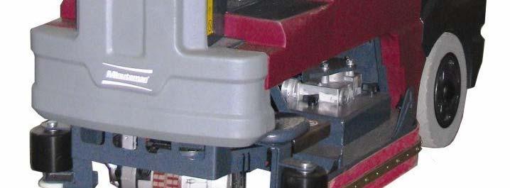
16 5.2 Squeegee Adjustment The clearance between the support roller and floor with squeegee unfolded (Factory setting) is: Inches ± inches (3 mm ±0.5). Note: Some floor surfaces may require adjusting the caster washers for optimum performance. See following page. 3mm ± in ±.02 Page 16


17 5.2 Rear Squeegee Adjustment Page 17


18 7. Side Squeegee Adjustment Step 1: Lower Scrub deck by placing positioning arrow on Double Scrub Double Scrub Side Squeegee is flush with floor surface Page 18


19 7. Side Squeegee Adjustment (Disk Models) Step 2: Loosen both front and rear plastic knobs. Page 19
 Step 3: Lower Side squeegee")


20 7. Side Squeegee Adjustment (Disk Models) Step 3: Lower Side squeegee so the squeegee blade flairs at the bottom around the bend and down the straight edge. See the picture. Step 4: Re-Tighten Plastic Knobs. Page 20
 Cylindrical Models Side Squeegees Adjustment Place the machine in the Double")


21 7. Side Squeegee Adjustment (Cyl. Models) Cylindrical Models Side Squeegees Adjustment Place the machine in the Double Scrub mode. Loosen the two black knobs (B). The blade should be adjusted so that it flairs on the bottom around the corner and along the straight edge. The side squeegees should also flair outward when traveling straight forward. Tighten the black plastic knobs. Accessing the Brushes Remove the yellow knob (C). The squeegee assembly will hinge open. The brush access plate (E) Is now accessible. B Page 21

 will swing")

. Cylindrical Brush Hub The access")

22 8. Cylindrical Brushes Side Squeegee Pivot Once the yellow knob has been removed. The side squeegee pivot (1) will swing open allowing access to the brush access place. Remove the three black plastic knobs (2). Cylindrical Brush Hub The access plate/idler hub (3) can be removed to access the brushes. The brushes may be removed without tools. Brush access plate/idler hub (3) Page 22


23 8.1 Cylindrical Brush Replacing the Cylindrical Brush Remove the access plate hub from the old brush. Discard the old brush. Stand the new brush on end with the slots on the bottom. Press the Idler hub into the top end of the new cylindrical brush. Slide the slotted the end of the brush deck first. Align the slots of the brush with the drive pin and push into the brush deck. Install the three plastic nuts. Rotate the brushes by hand, before tightening the plastic nuts, to prevent the bristles from getting caught between the housing and idler hub plate. Tighten the three plastic nuts. Close the squeegee pivot weldment and install the yellow knob. Repeat the process on each side. Page 23


24 9. Brush Pressure Settings The brush pressure range can be changed when changing the type of deck on the Hakomatic Scrubber Dryer 100R models. Connect the orange/violet wire into the terminal block with red/black wire group for cylindrical decks and unplug it for the disk or plate decks. The terminal block is located below the controller on the operators left side and below the seat behind the metal panel. Brush current Settings Orange/Violet wire Terminal Block Connect the orange/violet wire to this group with the red/black wires when using the cylindrical brush decks. Page 24


25 10. Static Chains Static chains on the decks, must touch the floor, when the brush deck is in the down position. They should be tested for continuity to the frame at each service interval. Replace, if worn or damaged. Failure to maintain the static chains may cause damage to the electronic controller. Disk Decks The static chain is attached to the motor and dhangs off ffthe rear side of fthe brush deck. Cylindrical Decks The static chain on the cylindrical deck is mounted on the side between the belt cover and the brush access plate. Page 25


26 10.1 Static Chain The Rear Static Chain is located between the two rear wheels. It should be present and must always drag on the floor. It should have continuity to the frame. Page 26


27 11. Service Mode The Service mode switch is located on the operators right side behind the metal panel below the seat. The Service mode switch can be used to lower the deck when servicing the brush deck assembly. Press and hold the lower side of the switch for 15 seconds. The deck will lower. Pressing the upper side will raise the deck. The brush deck may be removed, when it s down for easier servicing. The controller will go back to normal operation by turning the key switch off. Page 27
28 12. Changing Battery Types When changing from the wet lead acid type to gel or agm batteries. The trio controller will need to be replaced with part number , in order to obtain maximum run time. Gel batteries can discharged to a lower voltage level than wet lead acid batteries. Trio Controller When changing from gel or agm to the wet lead acid batteries The trio controller will need to be replaced with part number , in order to obtain maximum life of the battery. Wet lead acid batteries should not be discharged as low as gel and agm types. The battery charger must match the type batteries that are being used. Page 28
 tank.")


29 13. Solution Control The pump box is located the lower rear area of the solution tank. Drain the recovery (dirty water) tank. Release the rubber latches on the recover tank and tilt back to access the pump box. The pump box includes the solution filter, electric water solenoid and the water pump. Pump Box The water volume is regulated by the controller. The controller does this by adjusting the voltage to the pump. The operator can adjust the water level with the 5k potentiometer on the dash board. Solution Control Potentiometer Page 29
30 14. Trouble Shooting (Electrical) Trouble Shooting Electrical Problems on the E Ride 26 The E Ride uses a state of the art electronic circuitry with several diagnostic features. The battery indicator serves two purposes. They are: a. To display the charge status of the batteries on the LED display. This uses 10 LED bars, for example: 10-lighted LED bars indicates a fully charged battery, 5-lighted LED bars, indicates batteries are discharged 50%, 1-lighted LED indicates the batteries are discharged and so on. b. To display error codes for easier diagnosis of electrical problems. These are displayed by flashing a quantity of LED bars in different sequences. The deferent flash sequences are as follows: Rippling: One LED bar lighted, then two LEDS, then three LEDS and so on until all ten LEDS are lighted. Then it starts over. Flashing Steadily: Flashing a set amount of LEDS for each error code on and off steadily. The number of LEDS lighted indicates the type of error detected. Flashing in Sequence: Flashing a set amount of LEDS for each error Code in a pulse sequence. Example: The four LEDS flashes two times then pauses, then it repeats itself. Page 30


31 14.1 Error Code Decal Page 31
32 14.2 Error Codes Single flash Low Batteries- Charge the batteries Single flash Traction drive motor disconnected Single flash - Brush motor disconnected Single flash - Brush actuator overload Two flash Squeegee actuator overload Page 32
33 14.2 Error Codes Single flash Vacuum motor disconnected Single flash- Off Isle Wand Activated Single flash- Potentiometer Fault Single flash- Control fault check all connections to controller- see Trouble Shooting the Code 8 Error Page 33
34 14.2 Error Codes Single flash- Solution tank empty- Riders only Five flash-electric brake circuit fault- Check all connections to the brake on the chassis drive. Single flash- High battery voltage- Loose Connection Check all connections between the batteries and the controller, including the circuit breaker. Ripple-Throttle activated during start up. If throttle pedal was depressed during start up, release. If problem re-occurs: Check throttle return springs for breakage. Check potentiometer for fault or improper adjustment. Page 34
35 14.3 Code 8 Error 1. Check for loose or burnt connections on the controller, batteries, cables and the circuit breaker. 2. Make the sure the circuit breaker is not damaged. 3. Measure the total battery voltage at the batteries and at the battery connections on the controller. They should be exactly the same. A 1/10 of a volt or more difference would indicate a problem in the connections. 4. Check to see, if the operator has recently washed the machine down and got water inside of the brush motororinthecontrollerarea. or the 5. Check for a disconnected or an open circuit or faulty potentiometer on the throttle or speed circuit. Controller may not be detecting it in the circuit. Perform a continuity test. See Testing the Potentiometer section. 6. Disconnect one motor connector from the Trio controller at a time and disconnect the batteries for 1 minute and restart the machine. If the code 8 disappears and is replaced by a different code, the circuit disconnected should be considered suspect. For example the brush was disconnected. The code 8 is replaced by code 3. Code 3 indicates the brush motor is disconnected. 7. Check for a loose or broken connection at the brush deck. Check to see if water has gotten inside the brush motor. Check for a shorted motor. 8. Static electricity. Check both the ground chains: there is one on the brush deck and one on the rear of the machine. They should be contacting the floor. The one on the scrub deck should touch the floor only when the deck is down. They also should have continuity between the end of the chain and the frame of the machine. Repair or clean, if needed. 9. If everything checks OK, replace the Trio Controller. Note controllers can be damaged by loose connections on inputs and outputs, static electricity and water on electrical components such as on or in the controllers and motors. Page 35
36 14.4 Throttle Potentiometer Testing the Potentiometer 1. The throttle potentiometer resistance can be measured with an ohmmeter. 2. Unplug the throttle potentiometer at the connector next to it. 3. Analog type meters are recommended for this test. 4. Measuring across the black and white wires on the potentiometer, the resistance should be zero ohms with pedal on the riders in the neutral position in the full counterclockwise position. When the pedal is moved to the full throttle position, in should be a smooth resistance change without dropping out. It should measure 5K (5 thousand ohms) in the full position. 5. Measuring across the black and the red wire the resistance should be approximately 5K ohms (5 thousand), when in the neutral position. 6. When the pedal is at full throttle or the knob is full speed position, the resistance should drop to zero. 7. Loosen the nut and screw on the throttle arm and adjust if needed. 8. It can also be tested at the P3 connector on the controller to insure a good connection to the controller. Unplug the P3 connector from the controller. The throttle must be plugged into the harness while testing. See below. Note: when moving the throttle to the full position, the resistance should be smooth, without dropping out for both tests. If the resistance does not go to 5K during the test, the arm and the potentiometer may need to be adjusted to achieve it. Page 36
37 14.4 Potentiometer 8. If they do not find a problem here, have them retest at the connector at the Trio controller. Reconnect the plug at the throttle potentiometer. 9. Unplug the P3 connector (The large white connector) on the controller below the seat, behind the rear panel. 10. Locate the black/orange and the black/pink wire. 11. Measuring across the black/orange and black/pink wires the resistance should be zero ohms in the neutral position. It should be approximately 5k in the full throttle position. When the pedal is at full throttle the resistance should drop to zero. 12. Measure across the black/pink and the black/white wires. The resistance should be approximately 5K (5 thousand) in the neutral position. 13. It should drop to zero ohms with the throttle in the full position. 14. If your reading is different with this test check all the connections between the controller and the throttle control, including the seat switch. black/white black/pink black/orange Page 37
38 14.5 Trouble Shooting (Mechanical Problems) Problem Possible Causes Solution The brush puts down too much Worn brushes Replace the brushes if worn pressure The brush puts down too much pressure The brush puts down too much pressure The belt is slipping or broken (cylindrical models only) Only one brush is turning (disk models) Inspect the belt and bearings Replace the belt, if broken or slipping. Replace the bush bearings, if defective Replace the motor with the gearbox The brush puts down too much pressure The deck is tilted Replace the bent lift linkages The brush deck will not lift Broken linkage, pins missing, actuator is not working Replace the defective or missing parts The brush deck is tilted Bent linkage Replace the bent linkage Cylindrical brushes are worn Bent lift linkages or twisted brush Replace the defective part unevenly weldment Page 38

39 15. Lubrication Points Lubrication Squeegee Mechanism Lubrication Points Page 39
40 16. Carbon Brushes Replace the carbon brushes on or before on the following: Vacuum Motor at 1000 hours of operation Brush Motors (all) at 2000 hours of operation Chassis Drive Motor 3000 hours of operation Page 40


41 17. Circuit Breakers Breaker # Description Amp Main Circuit Breaker 2 3 Amp for Accessories Only 3 18 Amp Brush Motor 1 Cylindrical Only 4 18 Amp Brush Motor 2 Cylindrical Only Note Disk models do not have circuit breakers 3 and 4 Page 41


42 18. Electric Brake The chassis drive motor uses a electric brake system. The lever can be used to unlock the brake, in the event the machine can not move on it s own power. When the brake is released the machine will be easier to push. Pull lever away from the chassis drive motor to release. The lever will need to be wedged to hold the brake in the released position. See the following page. The brake will automatically lock the chassis drive, when the lever is released. The brake will be electronically released, when the drive system is activated. Front of the machine Lever Pull the lever away from the motor to release and hold. Page 42


43 18. Electric Brake Wedging the Brake The brake can be disengaged by putting a wedge or a small screwdriver (shown) behind lever arm to hold it away from the brake body. Use caution not to force to the lever out to far. Damage may occur. Do not leave the lever permanently wedged. Small Screw Driver Page 43
44
45
46
47
48
49 20. Notes Page 49
USER S OPERATING AND INSTRUCTION MANUAL
 Grand Rapids, Michigan, U.S.A. 49504-5298 USER S OPERATING AND INSTRUCTION MANUAL MODEL 2005 VARIABLE SLICE THICKNESS BREAD SLICER 2005S20000-CV INDEX Section Description Document No. Page No. SAFETY INSTRUCTIONS
Car and Counterweight Frames
 Car and Counterweight Frames CAR FRAME (SLING) AND PLATFORM COUNTERWEIGHT FRAME Every attempt has been made to ensure that this documentation is as accurate and up-to-date as possible. However, Vertical
BUSH HOG LAND MAINTENANCE REPAIR PARTS MANUAL MODELS: HS1736B, HS1742B, HS1836B, HS1842B, HS2036K, HS2042K HOME SERIES ZERO TURN MOWER SECTION: 85
 BUSH HOG LAND MAINTENANCE REPAIR S MANUAL MODELS: HSB, HSB, HSB, HSB, HS0K, HS0K HOME SERIES ZERO TURN MOWER SECTION: 0 Griffin Ave. Selma, AL 0 () -00 Parts Ordering -00-0- Fax -00-- www.bushhog.com OCTOBER,00
TALON Cargo Hook Troubleshooting Guide
 TROUBLESHOOTING GUIDE 125-004-00 Revision 1 As of: August 14, 2009 For all TALON Cargo Hooks TALON Cargo Hook Troubleshooting Guide TALON LC Hydraulic Hook TALON LC Cargo Hook TALON LC Keeperless Hook
HYDRAULIC DOCK LEVELER OWNERS MANUAL
 HYDRAULIC DOCK LEVELER OWNERS MANUAL 1 HYDRAULIC DOCK LEVELER OWNERS MANUAL 2 TABLE OF CONTENTS Table Of Contents.. Page 2 Koke Hydraulic Leveler Model Information... Page 3 Hydraulic Dock Leveler Installation
MICRO PRODUCTS COMPANY MANUFACTURERS OF PRECISION WELDING MACHINES RW 1,2,3,4 RING/BUTT WELDERS SERVICE MANUAL
 MICRO PRODUCTS COMPANY MANUFACTURERS OF PRECISION WELDING MACHINES RW 1,2,3,4 RING/BUTT WELDERS SERVICE MANUAL 1 TABLE OF CONTENTS 1.0 SPECIFICATIONS 2.0 GENERAL HOOK-UP INSTRUCTIONS 3.0 GENERAL OPERATING
Imperial Series. Model IMP-425/525/625/825/1000AP IMD-425/525/625/825/1000AP IMP-1025/1200/1500/2000AP IMD-1025/1200/1500/2000AP
 Service Manual Imperial Series Model IMP-425/525/625/825/1000AP IMD-425/525/625/825/1000AP IMP-1025/1200/1500/2000AP IMD-1025/1200/1500/2000AP Contents of Service Manual 1. Safety Precautions ------------------------------------------------------------------
Instructions for Continued Airworthiness Talon LC Keeperless Cargo Hook Kit For the AS350 Series. System Part Number STC SR00886SE
 Instructions for Continued Airworthiness Talon LC Keeperless Cargo Hook Kit For the AS350 Series System Part Number 200-261-00 STC SR00886SE 13915 NW 3 rd Court Vancouver Washington 98685 USA Phone: 360-546-3072
WELCOME. Standard Change Makers, Inc. Changer Maintenance Overview General Maintenance Guide for Standard Change-Makers Machines
 WELCOME Standard Change Makers, Inc. Changer Maintenance Overview - - - General Maintenance Guide for Standard Change-Makers Machines Service Maintenance School Reviewing: The SC System Product Line. The
Thank you for purchasing the SC-CONVERSION System 500/600 Conversion Kit. This Kit is available in two different versions:
 Rev. 1 (Jun 30, 2016) Thank you for purchasing the SC-CONVERSION System 500/600 Conversion Kit. This Kit is available in two different versions: Part # 4K01328-FI SC-CONVERSION Conversion Kit with MEI
FW66 FORESTRY WINCH FW66. Owner s Manual 19/02/2016
 FW66 FORESTRY WINCH FW66 19/02/2016 Owner s Manual TABLE OF CONTENTS INTRODUCTION ---------------------------------------------------------------------------------- 2 INTENDED USE -----------------------------------------------------------------------------------
TECHNICAL SPECIFICATION
 TECHNICAL SPECIFICATION ABP SERIES OF AUTOMATIC BLISTER PACKAGING MACHINERY Ridat ABP series of machines are some of the most advanced models in the comprehensive range of Ridat blister packaging equipment.
Power Stak. Installation, Operation and Service Manual PPS AS FOR UNITS SHIPPED PRIOR TO MARCH Model Number. Serial #
 Power Stak PPS2200-150AS FOR UNITS SHIPPED PRIOR TO MARCH 2014 Installation, Operation and Service Manual Model Number Serial # Date Placed in Service IMPORTANT: READ CAREFULLY BEFORE INSTALLING OR OPERATING
MET-FAB FABRICATION & MACHINE, INC. P.O. Box 363, Batavia, Ohio Ph. (513) Fax (513)
 Fax (513)") 1 2 MET-FAB FABRICATION & MACHINE, INC. P.O. Box 363, Batavia, Ohio 45103 Ph. (513) 724-3715 Fax (513) 724-1336 The people who can help you with your material handling needs Fact! A note about our references.
1 2 MET-FAB FABRICATION & MACHINE, INC. P.O. Box 363, Batavia, Ohio 45103 Ph. (513) 724-3715 Fax (513) 724-1336 The people who can help you with your material handling needs Fact! A note about our references.
MICRO WELD MODEL GP1, GP2 CERAMIC FUSION BUTT WELDERS MICRO PRODUCTS COMPANY SERVICE MANUAL
 MICRO WELD MODEL GP1, GP2 CERAMIC FUSION BUTT WELDERS MICRO PRODUCTS COMPANY SERVICE MANUAL 1 TABLE OF CONTENTS 1.0 SPECIFICATIONS 2.0 GENERAL OPERATING INSTRUCTIONS 3.0 BASIC OPERATING PARTS 4.0 BASIC
RAPiD VEHICLE SAFE. Owner s Manual. Instructional videos for Hornady Security products are available at hornady.com. With patented RFID technology.
 Owner s Manual RAPiD VEHICLE SAFE With patented RFID technology. Item No. 98210 Instructional videos for Hornady Security products are available at hornady.com. READ THIS FIRST Warning: NEVER store a loaded
Instruction Manual HK285. Note: The Owner/Operator must read carefully and understand all the information presented here before operation.
 Instruction Manual HK285 Note: The Owner/Operator must read carefully and understand all the information presented here before operation. Contents Warnings and Safety Instructions 1 Receiving Instructions
Precise Versatile Consistent
 4 INDUCTION CASTING MACHINE Precise Versatile Consistent Priced well below other electronic induction casting machines in its class, the Modular 4 will precisely cast non-precious, semi-precious and precious
2 Ohm Nominal Component Speaker System OWNER S MANUAL
 2 Ohm Nominal Component Speaker System OWNER S MANUAL 1 page 1 SPL 60 Component Speaker System Congratulations on your purchase of the Soundstream SPL 60 Component Speaker System. When used with a high
PalletPal Pallet Inverter / Rotator
 PalletPal Pallet Inverter / Rotator Owner s Manual SOUTHWORTH PRODUCTS CORP PO Box 1380, Portland, ME 04104-1380 Telephone: 1-800-743-1000 or 207-878-0700 Fax: 207-797-4734 www.southworthproducts.com service@southworthproducts.com
TABLE OF CONTENTS SERVICE
 Manu ual Treadmill IMPORTANT: Read all instructions carefully before using this product. Retain this owner s manual for future reference. The specifications of this product may vary from this photo and,
Braun Commercial. RA300 Transit Ramp WARNING. Models: BF3248Y-2 BF3255Y-2 BF3455Y-2 BF3262Y-2 BF3462Y-2 BF3462Y-2PA
 Operator's/Installation/Service Manual Braun Commercial RA300 Transit Ramp for Low-Floor Transit Vehicles Models: BF3248Y-2 BF3255Y-2 BF3455Y-2 BF3262Y-2 BF3462Y-2 BF3462Y-2PA WARNING Manual "Providing
Magner /35-3 Series Currency Counter. Operator's Manual
 Magner 35-2003/35-3 Series Currency Counter Operator's Manual Magner 35-2003 / 35-3 Series Introduction. The MAGNER 35-2003 / 35-3 is the most advanced Currency Counter available today. MAGNER's Design
Operating Instructions
 Operating Instructions A-2600 SERIES AWWA SWING CHECK VALVE 500 West Eldorado Street Decatur, Illinois 62522 www.muellercompany.com! WARNING! 1. Read and follow all pertinent instructions carefully. Proper
ENG. Instruction Manual. Turbo SFcompact. LNS Turbo 203 Turbo Drive Kings Mountain, NC 28086
 Instruction Manual ENG Turbo SFcompact LNS Turbo 203 Turbo Drive Kings Mountain, NC 28086 IMPORTANT READ CAREFULLY BEFORE USE AND KEEP FOR FUTURE REFERENCE. Published: 11/2016 LNS SA 2016 9.900.002.1.EN
Instruction Manual HT 24 BM-D2400 Homogenizer
 Instruction Manual HT 24 BM-D2400 Homogenizer Foreword Thank you for purchasing a HT 24 Homogenizer. This manual contains instructions for the proper operation and care of this instrument. Please read
General Guidelines. Tools Required. Instructions for Part # SC500-AF. Safety
 Instructions for Part # SC500-AF General Guidelines It is the user s responsibility to read and follow all instructions. Keep these instructions with the product at all times and review before each use.
Conversion Station Model 711
 Conversion Station Model 711 Automatic Tag Dispenser Guide 3M Library Systems 3M Center, Building 225-4N-14 St. Paul, Minnesota 55144-1000 www.3m.com/library Copyright 2000-2004, 3M IPC. All rights reserved.
BakeMax Dough Mini Moulder BMMDM02
 BakeMax Dough Mini Moulder BMMDM02 2 Instruction Manual 1. Preface ------------------------------------------- P2 2. Machine Introduction -------------------------------- P2 3. Machine Specification and
USER MANUAL FOR MORE INFORMATION
 USER MANUAL FOR MORE INFORMATION Visit us online at force1rc.com for product information, replacement parts and flight tutorials. ATTENTION: BEFORE FLYING YOUR DRONE, PLEASE WATCH THIS FLIGHT INSTRUCTION
2007 Ricoh Corporation 5 Dedrick Place West Caldwell, NJ January B. Container Stacker Unpacking & Setup Instructions
 2007 Ricoh Corporation 5 Dedrick Place West Caldwell, NJ 07006 January 2007 337641-006B Container Stacker Unpacking & Setup Instructions 2007 Ricoh Corporation. All rights reserved. No part of this document
GMV Super Star. Part List
 GMV Super Star Part List 25 Table of Contents Part List 25 Magazine... 28 Target Retainer... 30 Throwing Table... 31 Main Frame... 32 Turntable... 33 Base... 34 Elevator... 35 Throwing Arm... 36 Motor...
AP5K-C Precision AC Double-Pulse Spot Welding Machine User s Manual Shenzhen Will-Best Electronics Co., Ltd
 AP5K-C Precision AC Double-Pulse Spot Welding Machine User s Manual Shenzhen Will-Best Electronics Co., Ltd 1 Content 1. Introduction...3 1.1 Functions...3 1.2 Units of AP5K-C...4 2. The Initial Installation
BESTMOVE STANDING TRANSFER AID
 BESTMOVE STANDING TRANSFER AID L.L.C. MODELS BestMove 400 BestMove 450 PRODUCT FEATURES *BestMove 450 shown Ensure the product has been assembled according to the instructions in this manual. OPERATING
TF20 Tray Feeder. Instruction Manual. for JEDEC and IEC Standard Trays
 for JEDEC and IEC Standard Trays Instruction Manual 096-0243-003 Data I/O assumes no liability for errors, or for any incidental, consequential, indirect, or special damages, including, without limitation,
MODELS PH PH PH
 WWW.BURCAM.COM 2190 Boul. Dagenais West TEL: 514.337.4415 LAVAL (QUEBEC) FAX: 514.337.4029 CANADA H7L 5X9 info@burcam.com Your pump has been carefully packaged at the factory to prevent damage during shipping.
Electrical Systems: Theory and Operation
 Turf Equipment Management Program Turf Equipment Technician Certificate Study Guide Electrical Systems: Theory and Operation Table of Contents Turf Equipment Technician Exam Background... 1 Exam Structure
HM-Series. Dock Leveler. Owner s/user s Manual
 HM-Series Dock Leveler Owner s/user s Manual POWERAMP Division of Systems, Inc. W194 N11481 McCormick Drive Germantown, WI 53022 800.643.5424 fax: 262.257.7349 www.docksystemsinc.com techservices@docksystemsinc.com
Troubleshooting Guide 9702 Series
 Troubleshooting Guide 9702 Series Satellite Solutions for Mobile Markets 11200 Hampshire Avenue South, Bloomington, MN 55438-2453 Phone: (800) 982-9920 Fax: (952) 922-8424 www.kingcontrols.com 1305-AUTO
1. Vertical reciprocating conveyor, Hydraulic straddle VRC.
 PART 1: GENERAL 1.01 Section Includes: 1. Vertical reciprocating conveyor, Hydraulic straddle VRC. a. Machine, controller, platform, structural steel hoist frame. b. Wire mesh enclosure and gates. Related
Cutlass Fasteners, Inc. 83 Vermont Ave., Unit 6, Warwick, RI Tel: (401) Fax: (401) cutlass-studwelding.com
 Fax: (401) cutlass-studwelding.com") MODEL : PHM-12 ARC WELD GUN PART NO. : PHM-12 (PHM-12-RS) SERIAL NO. : PLEASE READ THIS OPERATION AND MAINTENANCE MANUAL CAREFULLY BEFORE USING YOUR NEW CUTLASS STUD WELDER. COPYRIGHT CFI 2009 email: sales@
MODEL : PHM-12 ARC WELD GUN PART NO. : PHM-12 (PHM-12-RS) SERIAL NO. : PLEASE READ THIS OPERATION AND MAINTENANCE MANUAL CAREFULLY BEFORE USING YOUR NEW CUTLASS STUD WELDER. COPYRIGHT CFI 2009 email: sales@
A-Series Aluminum Gantry Crane
 SPANCO PRODUCT SPECIFICATIONS 1 A-Series Aluminum Gantry Crane This guide can be used to prepare a bid specification for the incorporation of an A-Series Gantry Crane into a competitive bid project or
July P Wide Format Stacker User Guide
 July 2009 701P49768 Wide Format Stacker User Guide 2009 Xerox Corporation. All rights reserved. Xerox and the sphere of connectivity design are trademarks of Xerox Corporation in the United States and/or
300828TWP INSTALLATION INSTRUCTIONS MODEL SUBMERSIBLE SUMP PUMP
 www.burcam.com 2190 Dagenais Blvd. West TEL : 514.337.4415 LAVAL (QUEBEC) FAX : 514.337.4029 CANADA H7L 5X9 info@burcam.com Your pump has been carefully packaged at the factory to prevent damage during
XSTi Standby UPS. 400VA, 600VA, 800VA Models. User & Installation Manual
 XSTi Standby UPS 400VA, 600VA, 800VA Models User & Installation Manual www.xpcc.com 2015. All rights reserved. (Rev 12/14/15) Table of Contents Package Contents... 3 Product Introduction... 3 Product Overview...
LOS ANGELES COUNTY FIRE DEPARTMENT CONTEXT TRAINING PROGRAM FEBRUARY
 LOS ANGELES COUNTY FIRE DEPARTMENT FEBRUARY LOS ANGELES COUNTY FIRE DEPARTMENT POWER EQUIPMENT 2 3 1. General Information LOS ANGELES COUNTY FIRE DEPARTMENT CHAIN SAWS The following two (2) models of Stihl
MASTER. Water Conditioning Corp. OPERATION MANUAL. PURO PRO 1200 SCP Series Modular Reverse Osmosis System. January 2012 Version
 MASTER Water Conditioning Corp. www.masterwater.com OPERATION MANUAL PURO PRO 1200 SCP Series Modular Reverse Osmosis System January 2012 Version Table of Contents Model Number... 1 Shipping Description
Drag Chain Conveyor Installation and Operation Manual
 Drag Chain Conveyor Installation and Operation Manual Material Handling Equipment Sales, Incorporated 310 S. Section Line Rd Delaware, OH 43015 Phone: (989) 430-4005 Fax: (740) 363-9004 WARRANTY MATERIAL
E-Series Steel Gantry Crane
 SPANCO PRODUCT SPECIFICATIONS 1 E-Series Steel Gantry Crane This guide can be used to prepare a bid specification for the incorporation of an E-Series Gantry Crane into a competitive bid project or application.
TITAN Quadcopter Assembly Instructions 1
 TITAN Quadcopter Assembly Instructions Even if you have built a multirotor before; please read these instructions carefully! There are a lot of tricks in here that can save you headaches in the future
Forestry Mulching Disk
 Forestry Mulching Disk Owner s/operator s Manual For safe operation, read these rules and instructions carefully to avoid accidents that could result in Death or Serious Injury. TO THE OWNER/OPERATOR OF
Shur-Shot X-Proof Hydrogen Fluoride Alarm Operations Manual
 Shur-Shot X-Proof Hydrogen Fluoride Alarm Operations Manual P/N 1000006053 Rev E $7%$QDO\WLFV// //& 733 Dairy Rd. Parkton, Md. 21120 www.atbanalytics.com (410) 733-6365 Table of Contents Chapter 1: Getting
Original Operating Manual. Container-Filler CFM 20 CFM 40 CFM 45
 Original Operating Manual Container-Filler CFM 20 CFM 40 CFM 45 Version: March 2013 Contents Page 1 General Information... 4 1.1 Warranty... 4 1.2 Safety information... 4 1.3 Documentation... 6 1.4 Copyright...
HELIUM CADMIUM LASER INSTRUCTION MANUAL
 HELIUM CADMIUM LASER INSTRUCTION MANUAL FOR LASER HEAD POWER SUPPLY IK4301R-D IK4401R-D IK3083R-D IK3101R-D IK3152R-D IK3202R-D IK5351R-D IK5352R-D IM1301C IK4601R E IK3151R E IK3252R E IK5451R-E IK5452R-E
Ignition Switch Replacement for 850/70 Series ipd # , #
 PI-359 12/07 Dedicated to improving vehicle fun, safety & performance Installation Instructions Ignition Switch Replacement for 850/70 Series ipd #9447803, #9447804 SUGGESTED TOOLS Torx bit set includes
PSP Series Water Purification Systems
 Operations and Maintenance Manual for PSP Series Water Purification Systems PSP-1000 PSP-1600 PSP-2700 Rev. 2 / 08/26/14 Compact Design, Self-Contained Water Processing Unit for Point-Of-Use or Point-Of-Entry
RHE3 Dock Leveler Installation Manual
 RHE3 Dock Leveler Installation Manual MADE IN U.S.A. This Manual Covers Dock Levelers Built After Serial Numbers: 07FE160001M and up PRINTED IN U.S.A. RITE-HITE PRINT SHOP PUBLICATION NO. 1222 MAY 2007
User s Manual Installation, Operations, Maintenance and Parts. Mechanical Dock Levelers Models CM, WL and WS with HYDRA-CAM Lip Extension
 Mechanical Dock Levelers Models CM, WL and WS with HYDRA-CAM Lip Extension This manual applies to dock levelers manufactured beginning November 2013 with the serial numbers 61095303 and higher Do not install,
dronium TWO AP DRONE with camera
 dronium TWO AP TM DRONE with camera INSTRUCTION MANUAL WWW.PROTOCOLNY.COM THANK YOU. Thank you for your purchase of Protocol s Dronium Two AP With Camera. You are about to experience the best of what remote
PF-Series Gantry Crane
 SPANCO PRODUCT SPECIFICATIONS 1 PF-Series Gantry Crane This guide can be used to prepare a bid specification for the incorporation of a PF-Series Gantry Crane into a competitive bid project or application.
MASTER. Water Conditioning Corp. OPERATION MANUAL. PURO PRO 1200 SC Series Modular Reverse Osmosis System. January 2012 Version
 MASTER Water Conditioning Corp. www.masterwater.com OPERATION MANUAL PURO PRO 1200 SC Series Modular Reverse Osmosis System January 2012 Version Table of Contents Model Number... 1 Shipping Description
DCL-Series Drum Carriers Instruction Manual
 Vestil Manufacturing Corp. 2999 North Wayne Street, P.O. Box 507, Angola, IN 46703 Telephone: (260) 665-7586 -or- Toll Free (800) 348-0868 Fax: (260) 665-1339 www.vestilmfg.com e-mail: sales@vestil.com
FOUR FOLD DOORS-WITH SINGLE OVERHEAD MTD OPERATOR
 FOUR FOLD DOORS-WITH SINGLE OVERHEAD MTD OPERATOR Section 083713- Four Fold Doors- With Single Overhead Mounted Operator Part 1-General 1.1 Related Document: A. Drawing and general provisions of contract,
Safety on Heights: Our Policy
 11/17/14 Safety on Heights: Our Policy Only volunteers over the age of 18 are allowed to work on heights of more than six feet off the ground. This includes all work on scaffolds. Only volunteers who are
WP200e Wallbox to CD Changer Adapter
 WP200e Wallbox to CD Changer Adapter Supported Wallbox Models AMI W-40 & W-80 & W-120, 40/80/120 Select AMI WQ-200, 200 Select Rock-Ola 1558 & 500, 160 Select Rock-ola 1555, 200 Select Rowe WRA, WRB &
Xerox Nuvera Xerox Production Stacker Operator Manual
 Software Version 11.6 October 2012 702P00782 Xerox Nuvera Xerox Production Stacker Xerox Nuvera 100/120/144/157 EA Production System Xerox Nuvera 100/120/144 MX Production System Xerox Nuvera 200/288/314
1200 Portable Carpet Extractor Extractor Portátil de Alfombras
 ENGLISH - ESPAÑOL 100 Portable Carpet Extractor Extractor Portátil de Alfombras Operator and Parts Manual Manual del Operador y Piezas TENNANT COMPANY Commercial Products RANSOM STREET HOLLAND MI 9 U.S.A.
Bosch TCE 4470 and TCE 4475 A new standard in professional tire changing
 Bosch TCE 4470 and TCE 4475 A new standard in professional tire changing TCE 4470 and TCE 4475 Maximum performance and durability TCE 4470 S441 TCE 4475 S44 TCE 4470 and TCE 4475 are pneumatic tilting
LOAD RAMP 1000 LB. CAPACITY
 LOAD RAMP 1000 LB. CAPACITY 55424 ASSEMBLY AND OPERATING INSTRUCTIONS Safely roll Dirt Bikes and more into your Pickup! 3491 Mission Oaks Blvd., Camarillo, CA 93011 Visit our Web site at http://www.harborfreight.com
Instructions for 12 IGT system
 Instructions for 12 IGT system Step 1: IGT Site Preparation Site Location Several factors must be considered when choosing the site for your new In-Ground Trampoline (IGT) system. Since local soil and
MPE VG. HEAVY DUTY END RIDERS 6,000-8,000 lbs.
 MPE060-080VG HEAVY DUTY END RIDERS 6,000-8,000 lbs. YOU ASKED FOR A SOLUTION. WE DELIVERED. THE MPE060-080VG HEAVY DUTY END RIDERS. When it comes to end riders, you wanted a truck that gives you more.
BESTMOVE STANDING TRANSFER AID
 BESTMOVE STANDING TRANSFER AID L.L.C. MODELS BestMove 400 BestMove 450 PRODUCT FEATURES *BestMove 450 shown Ensure the product has been assembled according to the instructions in this manual. OPERATING
Installation. Smart-UPS VT in Parallel kva 380/400/415 V 208/220 V 200/208 V
 Installation Smart-UPS VT in Parallel 10-40 kva 380/400/415 V 208/220 V 200/208 V Contents Safety... 1 IMPORTANT SAFETY INSTRUCTIONS - SAVE THESE INSTRUCTIONS.............................. 1 Prepare for
Meteor Skid Steer Operator/Parts Manual
 Meteor Skid Steer Operator/Parts Manual M K Martin Enterprise Inc 3950 Steffler Rd Elmira On Ca N3B 2Z3 Tel: 519-664-2752 Toll Free 1-855-664-2752 Fax: 519-664-3695 e-mail: sales@mkmartin.ca www.mkmartin.ca
3500 Series Yellow Jacket Mild Steel Floor Scale
 Installation Manual 3500 Series Yellow Jacket Mild Steel Floor Scale 51233 2009-2014 by Fairbanks Scales, Inc. Revision 5 10/14 All rights reserved Amendment Record 3500 SERIES MILD STEEL FLOOR SCALE
VENTO WIFI DRONE WITH LIVE STREAMING CAMERA
 VENTO WIFI DRONE WITH LIVE STREAMING CAMERA INSTRUCTION MANUAL THANK YOU. Thank you for your purchase of Protocol s Vento Wifi Drone with Live Streaming Camera. You are about to experience the best of
Instruction Manual ODY-1765
 INSPIRING IMAGINATION Instruction Manual ODY-1765 We hope you enjoy your purchase of the Stealth NX-2 Drone and use this Instruction Manual to get your drone to take off! Included Contents 1. Stealth NX-2
Mechatronics Courses by School Period
 Mechatronics Courses by School Period Year One P1 P1 P2 P3 P3 P3 P4 P4 P4 Integrated Systems Industrial Math (Geometry, Trig, Algebra,) Blueprint Reading Machine Tool I (Hand tools-measuring-saws & Drill
min. 50min. 65min. PIT / P3 / P4 Ø
 Flush design Stop switch, IP 65 Equipment consisting of (schematic overview) 2 78 23 Actuator Anti-twist ring 2... 6 Pressure ring = Screw terminal Product can differ from the configuration. Bayonet flange
AHP WELDS USER MANUAL
 AHP WELDS USER MANUAL Alpha-TIG200X (version III) Contents 1. Safety... 2 2. About your AlphaTig 200X... 3 3. Parameters... 4 4. Panel Index... 5 5. Setup Instructions... 6 6. Operating Instructions...
NORTHWESTERN UNIVERSITY PROJECT NAME JOB # ISSUED: 03/29/2017
 SECTION 12 2113 - LOUVER BLINDS PART 1 - GENERAL 1.1 RELATED DOCUMENTS A. Drawings and general provisions of the Contract, including General and Supplementary Conditions and Division 01 Specification Sections,
U28. Name of Parts 1. Drone. Blade Guard. Battery Cover. Drone Body Blade Motor. Body Light. Camera. Landing Gear. Blade Guard Installation Diagram
 Name of Parts 1. Drone Blade Guard Drone Body Blade Motor Body Light Camera Landing Gear Blade Guard Installation Diagram U8 TF Card Installation Diagram . Transmitter Power Switch Throttle/ Up and Down
T-Series Gantry Crane
 SPANCO PRODUCT SPECIFICATIONS 1 T-Series Gantry Crane This guide can be used to prepare a bid specification for the incorporation of a T-Series Gantry Crane into a competitive bid project or application.
Low-profile, 11U high cabinets hold networking equipment, servers, and phone equipment.
 RM140A-R3 RM140A-M-R3 RM145A-R3 RM145A-M-R3 Small Office/Home Office (SOHO) Cabinets Low-profile, 11U high cabinets hold networking equipment, servers, and phone equipment. Fit under most desktops in the
GIGA Commercial Drone. Owner s Manual. For Owner s Manual updates, warranty information, and support, visit:
 GIGA -6000 Commercial Drone Owner s Manual For Owner s Manual updates, warranty information, and support, visit: www.mota.com/giga-6000 Please read the Owner s Manual before your first flight. It has information
ATV PULL BEHIND SPREADER OPERATION AND MAINTENANCE MANUAL
 ATV PULL BEHIND SPREADER OPERATION AND MAINTENANCE MANUAL INTRODUCTION TO THE OWNER: Read this manual before operating your equipment. Keep this manual handy for ready reference. Require all operators
Setup Guide. Snackvendor Models 170/ Enterprise Way Bridgeton, MO (314) August,
 August,") Setup Guide Snackvendor Models 170/171 12955 Enterprise Way Bridgeton, MO 63044-1200 (314) 298-3510 August, 1998 1700014 TABLE OF CONTENTS Specifications... ii Electrical Power Requirements... 1 Unpack
Setup Guide Snackvendor Models 170/171 12955 Enterprise Way Bridgeton, MO 63044-1200 (314) 298-3510 August, 1998 1700014 TABLE OF CONTENTS Specifications... ii Electrical Power Requirements... 1 Unpack
NVD-40 NEAR VERTICAL DRUM LIFTER INSTRUCTION MANUAL
 VESTIL MANUFACTURING CORP. 2999 North Wayne Street, P.O. Box 507, Angola, IN 46703 Telephone: (260) 665-7586 -or- Toll Free (800) 348-0868 Fax: (260) 665-1339 www.vestilmfg.com e-mail: info@vestil.com
OPERATOR S MANUAL. ACCU-CUT Q-9 Carpet and Vinyl Cut & Roll Machine. For Parts or Service contact Accu-Cut Support
 OPERATOR S MANUAL ACCU-CUT Q-9 Carpet and Vinyl Cut & Roll Machine For Parts or Service contact Accu-Cut Support 1-800-222-8288 Brockie International Inc. 28114 County Road 561, Tavares, Florida 32778
Operation Manual. 120V Lithium Ion Cordless Chainsaw MODEL #
 120V Lithium Ion Cordless Chainsaw MODEL # 106493 Operation Manual This safety alert symbol identifies important safety messages in this manual. Failure to follow this important safety information may
CORNER ELEMENTS CENTRE SUPPORT ACCESSORY BAG PROJECTION SCREEN BAG. 4 pieces- basic frame 52x52 cm (fig.: including SET UP SUPPORT,optional)
") FULLWHITE MANUAL CORNER ELEMENTS 4 pieces- basic frame 52x52 cm (fig.: including SET UP SUPPORT,optional) CENTRE SUPPORT Consists of plug in elements with integrated screw connection ACCESSORY BAG Yellow
FULLWHITE MANUAL CORNER ELEMENTS 4 pieces- basic frame 52x52 cm (fig.: including SET UP SUPPORT,optional) CENTRE SUPPORT Consists of plug in elements with integrated screw connection ACCESSORY BAG Yellow
HAAS SERVICE AND OPERATOR MANUAL ARCHIVE
 Haas Technical Publications Manual_Archive_Cover_Page Rev A June 6, 2013 HAAS SERVICE AND OPERATOR ARCHIVE Operators Manual 96-0012 RevE English June 2002 This content is for illustrative purposes. Historic
MP-Series. Dock Leveler. Owner s/user s Manual
 MP-Series Dock Leveler Owner s/user s Manual mcguire Division of Systems, Inc. W194 N11481 McCormick Drive Germantown, WI 53022 800.624.8473 fax: 262.255.9399 www.wbmcguire.com techservices@docksystemsinc.com
THE PICK FOR A NEW SOLUTION
 ELECTRIC POWERED ORDER PICKING TRUCK 8FBP 0.7 to 1.5 ton THE PICK FOR A NEW SOLUTION Get full support for order-picking operations at food warehouses, logistics centers, wholesalers, and a wide range of
ENVIRO-SEAL Packing System for Types A11, A31A, A31D and 8532
 Instruction Manual Form 50 January 000 ENVIRO-SEAL System Butterfly Valves ENVIRO-SEAL Packing System for Types A11, A1A, A1D and 85 Contents Introduction............................... 1 Scope of Manual.............................
Wash Down Duty Non-Contact Sensor
 Wash Down Duty Non-Contact Sensor Instruction Manual Models WDDC1-020/040/060/080/100 WDDC2-020/040/060/080/100 WDDV1-020/040/060/080/100 WDDV2-020/040/060/080/100 Table of Contents 1. General Description.....................................
U846. headless flying quad PRODUCT PARTS. 1. Quadcopter. Clockwise Blade A. Counter-clockwise Blade B. Counter-clockwise Blade B
 PRODUCT PARTS U846 headless flying quad 1. Quadcopter Clockwise Blade A Counter-clockwise Blade B Counter-clockwise Blade B Clockwise Blade A Clockwise Blade A Counter-clockwise Blade B USB Power 1 Power
B. Polyethylene samples shall be submitted for Owner approval of color and quality.
 Glass Rail ENGINEERED DASHERBOARD SPECIFICATIONS PART 1 - GENERAL 1.01 PROJECT SCOPE A. Contractor shall furnish and install one complete set of steel framed dasherboards as indicated on the drawings and
Owner s Manual & Safety Instructions
 Owner s Manual & Safety Instructions Save This Manual Keep this manual for the safety warnings and precautions, assembly, operating, inspection, maintenance and cleaning procedures. Write the product s
US PR-8. Instruction Manual. - approved
 2000-08 US GB PR-8 Instruction Manual - approved Preface You have just bought a Pro Spot PR-8. The use of microprocessor control in our vehicle body welding equipment has many benefits. It means, for example,