ISO : Rustam Rakhimov (DMS Lab)
|
|
|
- Erick Stokes
- 6 years ago
- Views:
Transcription
1 ISO : 2011 Rustam Rakhimov (DMS Lab)
2 Introduction Adaptation of IEC to road vehicles Influenced by ISO Quality Management System The first comprehensive standard that addresses safety related automotive systems comprised of electrical, electronic, and software elements that provide safety- related functions It intends to address the following important challenges in today s road vehicle technologies: The safety of new E/E and Software functionality in vehicles The trend of increasing complexity, software content, and mechatronics implementation The risk from both systematic failure and random hardware failure

3
4


5 General Structure of ISO 26262
6 Scope and Versions Conducted in June-July 2011, based on DSI draft published in Final standard (FDIS) was published in November Future discussions should be based on the FDIS version of the standard. Review Focus Understand how well can the standard provide safety assurance for the complex softwareintensive automotive electronics and electrical systems?

7 The ISO product lifecycle ISO is based on the concept of a safety lifecycle, shown in Figure 1, which consists of 6 phases: management, development, production, operation, service, and decommission. The goal of the standard is to maximize product safety by requiring specific steps to be taken during each of the phases. This ensures that safety is taken into consideration from the earliest conception of a vehicle to the point when the vehicle is retired from use. This document focuses primarily on the development phase, since this is the step in which embedded software is designed, developed, and validated.

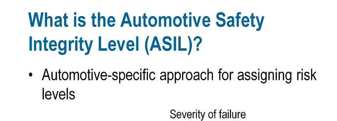
8 ASIL - Automotive Safety Integrity Level The ISO automotive safety integrity levels (ASILs) are A, B, C, and D, where ASIL level A represents the least amount of risk and level D represents the most. The ASIL for each component in a system is determined by three factors: Severity - is a measure of the health consequences of an event. There are four classes of severity, ranging from no injuries to life-threatening injuries. Probability - is the likelihood of the conditions under which a particular failure would result in a safety hazard. The probability of each condition is ranked on 5 point scale ranging from incredible to highly probable. For example, a failure of the headlights would result in a hazard when driving at night, when raining, or during other conditions which result in poor visibility which would be considered highly probable due to the regular occurrence of these conditions. Controllability - is a measure of the probability that harm can be avoided when a hazardous condition occurs, either due to actions by the driver, or by external measures. If the brakes fail to engage when the brake pedal is pressed, for example, the driver could use the emergency brake instead. The controllability of a hazardous situation is ranked on a four point scale from controllable in general to difficult to control or uncontrollable.

9

10 V Model The software development phase in ISO is subdivided into subphases according to a V-Model, as shown in Figure 3. The V shape is due to the fact that the testing and verification steps are performed in reverse order from design and implementation. Reactis can be used during each of the testing and verification steps.


11 Model-Based Design the value and importance of the model-based engineering paradigm is emphasized in Annex B of ISO
12 Parts of ISO Part 1 : Vocabulary Part 2 : Management of Functional Safety Part 3 : Concept phase Part 4 : Product Development: System Level Part 5 : Product Development: Hardware Level Part 6 : Product Development: Software Level Part 7 : Production and Operation Part 8 : Supporting Processes Part 9 : ASIL-oriented and Safety-oriented Analyses Part 10 : Guidelines on ISO 26262
13 This Presentation Is Divided into two Parts Overview for Each Parts of ISO Detail Study of ISO 26262
14 Overview for Each Parts of ISO 26262
15 Part 2 Management of Functional Safety General Safety Management: ISO assumes that the company has a defined, implemented and active QM system: Safety Culture, Communication, Qualification of Employees Specific Safety Management during development: ISO requires a Safety Manager (e.g. Project Leader) to control safety activities to develop a safety plan to confirmation measures based on the safety plan Safety reviews, safety audits or safety assessments
16 Part 3 Concept Phase It starts with the Item definition: System or array of systems to implement a function at the vehicle level to which ISO is applied: Specify the use and functionality Specify non-functional requirements like operating conditions, laws and standards to follow Based on the item definition, the Hazard Analysis and Risk Assessment is done: Goal of the risk assessment is: to assess the item risk to compare it to a public acceptable tolerable risk to define measures to reduce this risk The risk reducing measures are usually called Safety Integrity Level Automotive Safety Integrity Level - ASIL
17 Part 3 Concept Phase Hazard Analysis and Risk Assessment in practice: Identify operation states and driving situations of the item where th ere is a potential for hazards that are caused by this item Determine the potential error cases and misbehaviors by incorporati ng system FMEA (Failure mode and effect analysis) Usually analyzed on the vehicle level Define Safety Goals and Safe States Classify the results using Severity, Exposure and Controllability as measures

18 Part 3 Concept Phase/Product Development Functional safety concept defines the behavior of the vehicle in order achieve an intended function Technical safety concept defines, what one or more ECUs need to implement in order to achieve the intended behavior of the vehicle
19 Part 4 Product Development System Level Based on the functional safety concept, the technical safety concept is derived The technical safety requirements are mapped to system elements which are hardware or software based If a system component fails: means need to be specified which will detect the failure (self control) and a reaction needs to be present which will transition the system into a safe state After hardware and software development, there is hardware and software integration, followed by system integration and vehicle integration Item integration: Experimental testing (time and cost intensive) Reconfiguration of HW and SW Timing behavior (Analytics) Independence and Interference
20 Part 4 Product Development System Level Finally a validation shows, if the technical safety concept is able to reach the safety goals and if the safety goals and cases from the hazard analysis can be confirmed Development of HW and SW Validation: check if the right HW and SW has been developed Verification: check if the HW and SW has been developed right Check if QM measures have been taken into account Assess whether the mentioned points have been done correctly At the end, items are released for mass production Assessment Reports Safety case Existence of all documents required by ISO 26262
21 Part 4 Product Development System Level Item integration and testing Each functional and technical safety requirements shall be tested at least once in the complete integration phase
22 Part 5 Product Development Hardware Level The scope is to determine and plan the functional safety activities during the individual sub-phases of hardware development, which is included in the safety plan. The following metrics are used: Safe Faults do not affect the safety requirements Single point faults metric (SPFM) Is used to show, that the system architecture can detect single point faults. Latent faults metric (LFM) Is used to show, that the architecture is suitable to detect multiple faults (dualfaults). Residual Faults Fault which are not detected by any safety mechanisms and which lead to a violation of the safety requirements
23 Part 6 Product Development Software Level The scope is to plan and initiate the functional safety activities for the following sub-phases of the software development. Specifically, appropriate methods, and relative tools shall be determine to achieve the requirements of the assigned ASIL The main safety related software components are used for diagn ostic coverage The self control SW may have as many LOCs as the SW for function Key issues in the SW development process are: Model Based Development Software Configuration Freedom from Interference Requirements compared by ASIL 244 requirements ASIL A 308 requirements ASIL D
 Branch")
, foo(0, 1),")
24 Part 6 Product Development Software Level Metrics for SW Unit Testing Statement Coverage Call foo(1, 1) Branch Coverage Call foo(1, 1) and foo(0, 1) Modified Condition/Decision Coverage Call foo(0, 0), foo(0, 1), foo(1, 0), foo(1, 1)
25 Part 6 Product Development Software Level (Metrics for Software Testing) Function Coverage Makes sure, that a specific function gets called Call Coverage Makes sure that each function gets called
26 Part 7 Production and Operation Covers Production, Operation and Service Planning of the Activities and realization of the planned activities One important aspect is the Product observation duties which means that data from the field is communicated back to the OEM (Original equipment manufacturer). This data is the basis for the argumentation of proven in use.
27 Part 8 Supporting Processes Interfaces in case of distributed Development Specification Management of Safety Requirements Configuration Management Change Management Verification Documentation Qualification of Software Tools Qualification of Software Components Qualification of Hardware Components Argumentation of the Proven in Use
28 Detail Study of ISO-26262
29 ISO : 2011 Management of Functionality Safety
30 Scope Applied to the passenger cars with series production, that has features: Electrical or Electronic (E/E) systems Vehicle Mass up to kg Does not addresses Special purpose vehicles (such as drivers with disabilities) Hazards related to electric shock, fire, smoke, heat, radiation, toxicity, flammability, reactivity, corrosion, release of energy unless directly caused by malfunctioning behavior of E/E safety-related systems ISO : 2011
31 Part-2 specifies the Requirements for functional safety management for automotive applications Project-independent requirements with regard to the organizations involved Overall Safety Management Project-specific requirements with regard to the management activities in the safety lifecycle Management during the concept phase Product development After release for production ISO : 2011
32 Normative References ISO :2011, Road vehicles Functional safety Part 1: Vocabulary ISO :2011, Road vehicles Functional safety Part 3: Concept phase ISO :2011, Road vehicles Functional safety Part 4: Product development at the system level ISO :2011, Road vehicles Functional safety Part 5: Product development at the hardware level ISO :2011, Road vehicles Functional safety Part 6: Product development at the software level ISO :2011, Road vehicles Functional safety Part 7: Production and operation ISO :2011, Road vehicles Functional safety Part 8: Supporting processes ISO :2011, Road vehicles Functional safety Part 9: Automotive Safety Integrity Level (ASIL)-oriented and safety-oriented analyses ISO : 2011
33 Safety Lifecycle ISO : 2011
34 Plan Coordinate Track Key Management Tasks Requirements for the management of functional safety: Overall safety management Safety management during concept phase and product development Safety management after item s release for production ISO : 2011
35 Competence Management The organization shall ensure the persons involved in the execution of the safety lifecycle have a sufficient level of skills, competences and qualifications corresponding to their responsibilities to achieve a sufficient level of skills and competences in development is a training and qualification program: Usual safety practices, concepts and designs ISO and, if applicable, further safety standards organization-specific rules for functional safety functional safety processes instituted in the organization To evaluate the skills, competences and qualifications to carry out activities to comply with ISO domain knowledge of the item expertise on the environment of the item management experience Quality management during the safety lifecycle The organizations involved in the execution of the safety lifecycle shall have an operational quality management system complying with a quality management standard, such as ISO/TS 16949, ISO 9001 ISO : 2011
36 6. Safety management during the concept phase and the product development Objective Confirmation Measures should be performed. It include confirmation reviews, functional safety audits and functional safety assessments: the confirmation reviews are intended to check the compliance of selected work products to the corresponding requirements of ISO a functional safety audit evaluates the implementation of the processes required for the functional safety activities a functional safety assessment evaluates the functional safety achieved by the item ISO : 2011
37 Inputs to this clause The following information shall be available: organization-specific rules and processes for functional safety in accordance with (Organization-specific rules and processes for functional safety) evidence of competence in accordance with (Evidence of competence) evidence of quality management in accordance with (Evidence of quality management) Optionally: If available, the following information can be considered: project plan (from external source); dependencies on other activities, including other safety activities. ISO : 2011
38 Requirements and recommendations Roles and responsibilities in safety management A project manager shall be appointed at the initiation of the item development The project manager shall be given the responsibility and the authority, in accordance with , to ensure that: the safety activities required to achieve functional safety are performed compliance with ISO is achieved The project manager shall verify that the organization has provided the required resources for the functional safety activities, in accordance with The project manager shall ensure that the safety manager is appointed, in accordance with Planning and coordination of the safety activities The safety manager shall be responsible for the planning and coordination of the functional safety activities in the development phases of the safety lifecycle, in accordance with The safety manager shall be responsible for maintaining the safety plan, and for monitoring the progress of the safety activities against the safety plan The safety plan shall either be referenced in the project plan, or included in the project plan, such that the safety activities are distinguishable. ISO : 2011
39 The Safety Plan Shall Include The planning of the activities and procedures for achieving functional safety The implementation of project-independent safety activities in accordance with Clause 5 into project-specific safety management The definition of the tailored safety activities, in accordance with 6.4.5, if applicable The planning of the hazard analysis and risk assessment in accordance with ISO :2011, Clause 7 The planning of the development activities, including the development and implementation of the functional safety concept in accordance with ISO :2011 The planning of the development interface agreement (DIA) in accordance with ISO :2011 The planning of the supporting processes, in accordance with ISO The planning of the verification activities in accordance with ISO , ISO , ISO , ISO and ISO :2011 The planning of the confirmation reviews, the initiation of the functional safety audit(s) and the initiation of the functional safety assessment in accordance with to The planning of the analysis of dependent failures in accordance with ISO :2011 The provision of the proven in use arguments of the candidates in accordance with ISO :2011 The provision of the confidence in the usage of software tools in accordance with ISO :2011 ISO : 2011
40 Tailoring of the safety activities A safety activity with regard to a specific item development may be tailored (i.e. omitted or performed in a different manner): the tailoring shall be defined in the safety plan and a rationale as to why the tailoring is adequate and sufficient to achieve functional safety shall be available If the safety activities are tailored in accordance with because an element is developed separately from an item, then the development of the element developed separately from an item shall be based on a requirement specification that is derived from assumptions on an intended use and context, including its external interfaces the validity of the assumptions on the intended use and context of the element developed separately from an item shall be established Example: A microcontroller developed separately from an item. NOTE: ISO as a whole cannot be applied to an element developed separately from an item, because functional safety is not an element property (however, an element of an item can be identified as safety related). Functional safety is an item property which can be evaluated by means of a functional safety assessment ISO : 2011
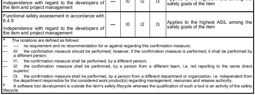
41 Confirmation measures: types, independency and authority The confirmation measures specified in Table 1 shall be performed, in accordance with the required level of independency, Table 2, i), and The persons who carry out a confirmation measure shall have access to, and shall be supported by, the persons and organizational entities that carry out safety activities during the item development. The persons who carry out a confirmation measure shall have access to the relevant information and tools. ISO : 2011
42
43
44 Functional safety audit A functional safety audit shall be carried out for items, where the highest ASIL of the item's safety goals is ASIL (B), C, or D, in accordance with 6.4.7, i) and One or more persons shall be appointed to carry out one or more functional safety audits, in accordance with The appointed persons shall provide a report that contains an evaluation of the implementation of the processes required for functional safety Note: If a functional safety audit is performed by a Software Process Improvement and Capability Determination (SPICE) assessor, then this functional safety audit and a SPICE assessment (see ISO/IEC 15504) can be performed simultaneously ISO : 2011
45 Functional safety assessment A functional safety assessment shall be carried out for items, where the highest ASIL of the item's safety goals is ASIL (B), C, or D, in accordance with and to A functional safety assessment shall be planned in accordance with and i). EXAMPLE: Agenda for a functional safety assessment given in Annex E. One or more persons shall be appointed to carry out a functional safety assessment, in accordance with The appointed persons shall provide a report that contains a judgment of the achieved functional safety The scope of a functional safety assessment shall include the work products required by the safety plan the processes required for functional safety reviewing the appropriateness and effectiveness of the implemented safety measures that can be assessed during the item development A functional safety assessment shall consider: the planning of the other confirmation measures [see i)]; the results from the confirmation reviews and functional safety audit(s) the recommendation(s) resulting from the previous functional safety assessment(s), if applicable (see , and ISO :2011, ) ISO : 2011
46 7. Safety management after the item's release for production Objective The objective of this clause is to define the responsibilities of the organizations and persons responsible for functional safety after the item's release for production. Inputs to this clause The following information shall be available evidence of quality management in accordance with > = The organizations involved in the execution of the safety lifecycle shall have an operational quality management system complying with a quality management standard, such as ISO/TS 16949, ISO 9001, or equivalent Requirements and recommendations Responsibilities, planning and required processes The organization shall appoint persons with the responsibility and the corresponding authority, in accordance with , to maintain the functional safety of the item after its release for production The activities for ensuring the functional safety of the item after its release for production shall be planned, in accordance with ISO , and shall be initiated during the product development at the system level in accordance with ISO The organization shall institute, execute and maintain processes in order to maintain the functional safety of the item in the lifecycle phases after the release for production. The organization shall institute, execute and maintain a field monitoring process with respect to the item's functional safety If the item changes after its release for production, the release for production in accordance with ISO :2011, Clause 11, shall be reissued ISO : 2011
47 Requirements and recommendations Responsibilities, planning and required processes The organization shall appoint persons with the responsibility and the corresponding authority, in accordance with , to maintain the functional safety of the item after its release for production The activities for ensuring the functional safety of the item after its release for production shall be planned, in accordance with ISO , and shall be initiated during the product development at the system level in accordance with ISO The organization shall institute, execute and maintain processes in order to maintain the functional safety of the item in the lifecycle phases after the release for production. The organization shall institute, execute and maintain a field monitoring process with respect to the item's functional safety If the item changes after its release for production, the release for production in accordance with ISO :2011, Clause 11, shall be reissued ISO : 2011


48 Functional safety management: overview ISO : 2011

49 Examples for Evaluating a Safety Culture ISO : 2011
50 Overview of Verification reviews ISO : 2011
51 ISO : 2011 Concept Phase
52 Contents Item Definition Initiation of the safety lifecycle Hazard analysis and risk assessment Functional safety concept ISO : 2011
53 Item Definition Objectives The first objective is: to define and describe the item its dependencies on interaction with the environment and other items The second objective is: to support an adequate understanding of the item so that the activities in subsequent phases can be performed. Further Supporting Information Any information that already exists: concerning the item a product idea a project sketch relevant patents the results of pre-trials the documentation from predecessor items relevant information on other independent items. ISO : 2011
54 Item Definition - Requirements and Recommendations The functional and non-functional requirements of the item as well as the dependencies between the item and its environment shall be made available the functional concept, describing the purpose and functionality, including the operating modes and states of the item; the operational and environmental constraints; legal requirements (especially laws and regulations), national and international standards; behavior achieved by similar functions, items or elements, if any assumptions on behavior expected from the item potential consequences of behavior short falls including known failure modes and hazards The boundary of the item, its interfaces, and the assumptions concerning its interaction with other items and elements, shall be defined considering: the elements of the item the assumptions concerning the effects of the item's behavior on other items or elements, that is the environment of the item; interactions of the item with other items or elements; functionality required by other items, elements and the environment; functionality required from other items, elements and the environment; the allocation and distribution of functions among the involved systems and elements the operating scenarios which impact the functionality of the item. ISO : 2011
55 Initiation of the safety lifecycle Objectives make the distinction between a new item development and a modification to an existing item define the safety lifecycle activities (ISO :2011, Figure 2) that will be carried out in the case of a modification Inputs to this clause any existing information, not already covered by the item definition, being useful for conducting the impact analysis (Item definition stands for Requirements and Recommendations). EXAMPLE: Product concept, requests for change, implementation planning, proven in use argument. ISO : 2011
56 Initiation of the safety lifecycle Requirements and recommendations Determination of the development category It shall be determined whether the item is either a new development, or if it is a modification of an existing item or its environment: in the case of a new development, the development shall be continued with the hazard analysis and risk assessment in accordance with Clause 7 in the case of a modification of the item or its environment the applicable lifecycle sub-phases and activities shall be determined in accordance with NOTE: A proven in use argument can be applied to modification ISO : 2011
57 Initiation of the safety lifecycle Requirements and recommendations Impact analysis and possible tailored safety lifecycle, in the case of modification An impact analysis shall be carried out in order to identify and describe the intended modification applied to the item or its environment and to assess the impact of these modifications The impact analysis shall identify and address areas affected by the modifications to the item and modifications between previous and future conditions of use of the item, including: operational situations and operating modes interfaces with the environment installation characteristics such as location within the vehicle, vehicle configurations and variants a range of environmental conditions e.g. temperature, altitude, humidity, vibrations, Electromagnetic Interference (EMI) and fuel types The implication of the modification with regard to functional safety shall be identified and described. The affected work products that need to be updated shall be identified and described. The safety activities shall be tailored in accordance with the applicable lifecycle phases. Tailoring shall be based on the results of the impact analysis. The results of tailoring shall be included in the safety plan in accordance with ISO :2011, The affected work products shall be reworked. NOTE: The affected work products include the validation plan (see ISO ). In the case of missing work products or work products that do not comply with ISO 26262, the necessary activities to reach ISO compliance shall be determined. ISO : 2011
58 Hazard analysis and risk assessment Objectives Identify and to categorize the hazards that malfunctions in the item can trigger and to formulate the safety goals related to the prevention or mitigation of the hazardous events, in order to avoid unreasonable risk ISO : 2011
59 Hazard analysis and risk assessment Requirements and recommendations Initiation of the hazard analysis and risk assessment The hazard analysis and risk assessment shall be based on the item definition. The item without internal safety mechanisms shall be evaluated during the hazard analysis and risk assessment Situation analysis and hazard identification Situation analysis The operational situations and operating modes in which an item's malfunctioning behavior will result in a hazardous event shall be described, both for cases when the vehicle is correctly used and when it is incorrectly used in a foreseeable way Hazard identification The hazards shall be determined systematically by using adequate techniques Hazards shall be defined in terms of the conditions or behavior that can be observed at the vehicle level The hazardous events shall be determined for relevant combinations of operational situations and hazards The consequences of hazardous events shall be identified Classification of hazardous events (Continue on next page) ISO : 2011
60 Hazard analysis and risk assessment Requirements and recommendations Situation analysis and hazard identification (Continue) Classification of hazardous events ISO : 2011 All hazardous events identified in shall be classified, except those that are outside the scope of ISO The severity of potential harm shall be estimated based on a defined rationale for each hazardous event. The severity shall be assigned to one of the severity classes S0, S1, S2 or S3 in accordance with Table 1. The severity class S0 may be assigned if the hazard analysis determines that the consequences of a malfunctioning behavior of the item are clearly limited to material damage and do not involve harm to persons. If a hazard is assigned to severity class S0, no ASIL assignment is required. The probability of exposure of each operational situation shall be estimated based on a defined rationale for each hazardous event. The probability of exposure shall be assigned to one of the probability classes, E0, E1, E2, E3 and E4, in accordance with Table 2. The number of vehicles equipped with the item shall not be considered when estimating the probability of exposure
61 Hazard analysis and risk assessment Requirements and recommendations Situation analysis and hazard identification (Continue) Classification of hazardous events ISO : 2011 The probability of exposure of each operational situation shall be estimated based on a defined rationale for each hazardous event. The probability of exposure shall be assigned to one of the probability classes, E0, E1, E2, E3 and E4, in accordance with Table 2. The number of vehicles equipped with the item shall not be considered when estimating the probability of exposure Class E0 may be used for those situations that are suggested during hazard analysis and risk assessment, but which are considered to be extremely unusual, or incredible, and therefore not followed up. A rationale shall be recorded for the exclusion of these situations. If a hazard is assigned to exposure class E0, no ASIL assignment is required
62 Hazard analysis and risk assessment Requirements and recommendations Situation analysis and hazard identification (Continue) Classification of hazardous events The controllability of each hazardous event, by the driver or other persons potentially at risk, shall be estimated based on a defined rationale for each hazardous event. The controllability shall be assigned to one of the controllability classes C0, C1, C2 and C3 in accordance with Table 3. ISO : 2011 Class C0 may be used for hazards addressing the unavailability of the item if they do not affect the safe operation of the vehicle (e.g. some driver assistance systems). Class C0 may also be assigned if dedicated regulations exist that specify the functional performance with respect to a defined hazard, and C0 is argued using the corresponding existing experience concerning sufficient controllability. If a hazard is assigned to the controllability class C0, no ASIL assignment is required.
63 ISO : 2011 Hazard analysis and risk assessment Requirements and recommendations Situation analysis and hazard identification (Continue) Determination of ASIL and safety goals An ASIL shall be determined for each hazardous event using the parameters "severity", "probability of exposure" and "controllability" in accordance with Table 4. It shall be ensured that the chosen level of detail of the list of operational situations does not lead to an inappropriate lowering of the ASIL of the corresponding safety goals.
64 ISO : 2011 Hazard analysis and risk assessment Requirements and recommendations Situation analysis and hazard identification (Continue) Verification The hazard analysis, risk assessment and the safety goals shall be verified in accordance with ISO :2011, Clause 9, to show their: completeness with regard to situations ( ) and hazards ( ); compliance with the item definition; consistency with related hazard analyses and risk assessments; completeness of the coverage of the hazardous events; and consistency of the assigned ASILs with the corresponding hazardous events.
65 Functional safety concept ISO : 2011 Objectives The objective of the functional safety concept is to derive the functional safety requirements, from the safety goals, and to allocate them to the preliminary architectural elements of the item, or to external measures. General It complies with the safety goals contains safety measures safety mechanisms implemented in the item s architectural elements and specified in the functional safety requirements The functional safety concept addresses: fault detection and failure mitigation; transitioning to a safe state; fault tolerance mechanisms, where a fault does not lead directly to the violation of the safety goal(s) and which maintains the item in a safe state (with or without degradation); fault detection and driver warning in order to reduce the risk exposure time to an acceptable interval (e.g. engine malfunction indicator lamp, ABS fault warning lamp) arbitration logic to select the most appropriate control request from multiple requests generated simultaneously by different functions.
 ISO 26262 3 : 2011")
66 Safety goals are determined as a result of the hazard analysis and risk assessment (Hierarchical Approach) ISO : 2011


67 Structure of the Safety Requirements ISO : 2011
68 Requirements and recommendations Derivation of functional safety requirements The functional safety requirements shall be derived from the safety goals and safe states, taking into account the preliminary architectural assumptions At least one functional safety requirement shall be specified for each safety goal Each functional safety requirement shall be specified by considering the following, if applicable: operating modes; fault tolerant time interval; safe states; emergency operation interval, and functional redundancies If a safe state cannot be reached by a transition within an acceptable time interval, an emergency operation shall be specified The warning and degradation concept shall be specified as functional safety requirements ISO : 2011
69 Requirements and recommendations Allocation of functional safety requirements The functional safety requirements shall be allocated to the elements of the preliminary architectural assumptions: During the course of allocation, the ASIL and information given in shall be inherited from the associated safety goal or, if ASIL decomposition is applied, from the level above. If several functional safety requirements are allocated to the same architectural element, then the architectural element shall be developed in accordance with the highest ASIL for those safety requirements if independence or freedom from interference cannot be argued in the preliminary architecture. If the item comprises more than one system, then the functional safety requirements for the individual systems and their interfaces shall be specified, considering the preliminary architectural assumptions. These functional safety requirements shall be allocated to the systems. If ASIL decomposition is applied during the allocation of the functional safety requirements, then it shall be applied in accordance with ISO :2011 ISO : 2011
70 Requirements and recommendations Validation The acceptance criteria for safety validation of the item shall be specified based on the functional safety requirements Verification of the functional safety concept The functional safety concept shall be verified in accordance with ISO :2011 its consistency and compliance with the safety goals its ability to mitigate or avoid the hazardous events ISO : 2011
71 Annex B Hazard analysis and risk assessment For this analytical approach, a risk (R) can be described as a function (F), with the frequency of occurrence (f) of a hazardous event, the ability to avoid specific harm or damage through timely reactions of the persons involved, that is the controllability (C) and the potential severity (S) of the resulting harm or damage: For this analytical approach, a risk (R) can be described as a function (F), with the frequency of occurrence (f) of a hazardous event, the ability to avoid specific harm or damage through timely reactions of the persons involved, that is the controllability (C) and the potential severity (S) of the resulting harm or damage: Hazard analysis and risk assessment is concerned with setting requirements for the item such that unreasonable risk is avoided ISO : 2011
72 ISO : 2011 Product development at the system level ISO : 2011
73 Main Contents Initiation of product development at the system level Specification of the technical safety requirements System design Item integration and testing Safety validation Functional safety assessment Release for production ISO : 2011
74 Initiation of product development at the system level Objectives The objective of the initiation of the product development at the system level is to determine and plan the functional safety activities during the individual sub-phases of system development. This also includes the necessary supporting processes described in ISO Planning of system-level safety activities will be included in the safety plan Prerequisites: The following information shall be available: Project plan (refined) in accordance with ISO :2011, 6.5.2; Safety plan in accordance with ISO :2011, 6.5.2; Functional safety assessment plan in accordance with ISO :2011, 6.5.4; and Functional safety concept in accordance with ISO :2011, ISO : 2011
75 Initiation of product development at the system level During System Design System Architecture is established The technical safety requirements are allocated to hardware and software [if applicable, on other technologies] When the development is done the hardware and software elements are integrated and tested to form an item that is then integrated into a vehicle Once integrated at the vehicle level, safety validation is performed to provide evidence of functional safety with respect to the safety goals ISO and ISO describe the development requirements for hardware and software ISO : 2011
76 Example of a product development at the system level ISO : 2011
77 Requirements and recommendations The safety activities for the product development at the system level shall be planned including determination of appropriate methods and measures during design and integration The validation activities shall be planned The functional safety assessment activities for the product development at the system level shall be planned (see also ISO ) The tailoring of the lifecycle for product development at system level shall be performed in accordance with ISO ISO : 2011
78 6 Specification of the technical safety requirements Objectives The first objective of this sub-phase is to specify the technical safety requirements. The technical safety requirements specification refines the functional safety concept, considering both the functional concept and the preliminary architectural assumptions (see ISO ) The second objective is to verify through analysis that the technical safety requirements comply with the functional safety requirements. General Within the overall development lifecycle, the technical safety requirements are the technical requirements necessary to implement the functional safety concept, with the intention being to detail the item-level functional safety requirements into the system-level technical safety requirements. Requirements and recommendations Specification of the technical safety requirements Safety mechanisms ASIL Decomposition - If ASIL decomposition is applied during the specification of the technical safety requirements it shall be applied in accordance with ISO :2011, (Requirements decomposition with respect to ASIL tailoring). Production, operation, maintenance and decommissioning Verification and validation ISO : 2011
79 Specification of the technical safety requirements The technical safety requirements shall be specified in accordance with the functional safety concept: the external interfaces, such as communication and user interfaces, if applicable; the constraints, e.g. environmental conditions or functional constraints; and the system configuration requirements. If other functions or requirements are implemented by the system or its elements, in addition to those functions for which technical safety requirements are specified in accordance with (Specification of the technical safety requirements), then these functions or requirements shall be specified or references made to their specification. The technical safety requirements shall specify safety-related dependencies between systems or item elements and between the item and other systems ISO : 2011
80 Safety mechanisms The technical safety requirements shall specify the response of the system or elements to stimuli that affect the achievement of safety goals. This includes failures and relevant combinations of stimuli in combination with each relevant operating mode and defined system state EXAMPLE: The Adaptive Cruise Control (ACC) ECU disables the ACC functionality if informed by the brake system ECU that the Vehicle Stability Control functionality is unavailable. The technical safety requirements shall specify the necessary safety mechanisms: the measures relating to the detection, indication and control of faults in the system itself the measures relating to the detection, indication and control of faults in external devices that interact with the system EXAMPLE: External devices include other electronic control units, power supply or communication devices the measures that enable the system to achieve or maintain a safe state the measures to detail and implement the warning and degradation concept the measures which prevent faults from being latent (Avoidance of latent faults) For each safety mechanism that enables an item to achieve or maintain a safe state the following shall be specified: the transition to the safe state the fault tolerant time interval the emergency operation interval, if the safe state cannot be reached immediately EXAMPLE 1: Switching off can be an emergency operation the measures to maintain the safe state EXAMPLE 2: A safety mechanism for a brake-by-wire application, which depends on the power supply, can include the specification of a secondary power supply or storage device ISO : 2011
81 Avoidance of latent faults This requirement applies to ASILs (A), (B), C, and D. if applicable, safety mechanisms shall be specified to prevent faults from being latent EXAMPLE: On-board tests are safety mechanisms which verify the status of components during the different operation modes such as power-up, power-down, at runtime or in an additional test mode to detect latent faults. Valve, relay or lamp function tests that take place during power up routines are examples of such on-board tests. This requirement applies to ASILs (A), (B), C and D, to avoid multiplepoint failures, the multiple-point fault detection interval shall be specified for each safety mechanism Following Parameters should be considered: the reliability of the hardware component with consideration given to its role in the architecture; the probability of exposure of the corresponding hazardous event(s); the specified quantitative target values for the maximum probability of violation of each safety goal due to hardware random failures the assigned ASIL of the related safety goal. ISO : 2011
82 Verification and validation The technical safety requirements shall be verified in accordance with ISO :2011, to provide evidence for their: compliance and consistency with the functional safety concept compliance with the preliminary architectural design assumptions The criteria for safety validation of the item shall be refined based on the technical safety requirements ISO : 2011
83 7 System design Objectives Develop the system design and the technical safety concept that comply with the functional requirements and the technical safety requirements specification of the item Verify that the system design and the technical safety concept comply with the technical safety requirements specification General The development of the system design and the technical safety concept is based on the technical safety requirements specification derived from the functional safety concept. This sub-phase can be applied iteratively, if the system is comprised of subsystems. safety-related and non-safety-related requirements are handled within one development process ISO : 2011
84 System design specification and technical safety concept With regard to the implementation of the technical safety requirements the following shall be considered in the system design: the ability to verify the system design the technical capability of the intended hardware and software design with regard to the achievement of functional safety the ability to execute tests during system integration Measures for the avoidance of systematic failures Identified internal and external causes of systematic failures shall be eliminated or their effects mitigated ISO : 2011
85 System architectural design constraints To reduce systematic failures, well-trusted automotive systems design principles should be applied. These may include the following re-use of well-trusted technical safety concepts; re-use of well-trusted designs for elements, including hardware and software components re-use of well-trusted mechanisms for the detection and control of failures re-use of well-trusted or standardized interfaces. To ensure the suitability of well-trusted design principles or elements in the new item, the results of their application shall be analyzed and the underlying assumptions checked before reuse This requirement applies to ASIL D: a decision not to re-use well-trusted design principles should be justified This requirement applies to ASILs (A), (B), C, and D, in order to avoid failures resulting from high complexity, the architectural design shall exhibit all of the following properties modularity; adequate level of granularity simplicity. ISO : 2011
86 Measures for control of random hardware failures during operation Measures for detection and control, or mitigation of random hardware failures shall be specified EXAMPLE 1: Such measures can be hardware diagnostic features and their usage by the software to detect random hardware failures EXAMPLE 2: A hardware design which directly leads to the safe state in the case of a random hardware failure controls a failure even without detection This requirement applies to ASILs (B), C, and D, the target values for single-point fault metric and latent-point fault metric, shall be specified for final evaluation at the item level This requirement applies to ASILs (B), C, and D, in accordance with 4.3:one of the alternative procedures of evaluation of violation of the safety goal due to random hardware failures shall be chosen and the target values shall be specified for final evaluation at item level This requirement applies to ASILs (B), C, and D, appropriate target values for failure rates and diagnostic coverage should be specified at element level in order to comply with: the target values of the metrics in ISO :2011, Clause 8; and the procedures in ISO :2011 ISO : 2011
87 Allocation to hardware and software The technical safety requirements shall be allocated directly or by further refinement to hardware, software or both If technical safety requirements are allocated to custom hardware elements that incorporate programmable behavior (such as ASICs, FPGA or other forms of digital hardware) an adequate development process, combining requirements from ISO and ISO , should be defined and implemented. Hardware-software interface specification (HSI) The HSI specification shall specify the hardware and software interaction and be The HSI specification shall specify the hardware and software interaction and be consistent with the technical safety concept. The HSI specification shall include the component's hardware devices that are controlled by software and hardware resources that support the execution of software The HSI specification shall include the following characteristics: the relevant operating modes of hardware devices and the relevant configuration parameters; EXAMPLE 1 Operating modes of hardware devices such as: default, init, test or advanced modes. EXAMPLE 2 Configuration parameters such as: gain control, band pass frequency or clock prescaler. the hardware features that ensure the independence between elements and that support software partitioning; shared and exclusive use of hardware resources (such as Memory mapping, allocation of registers, timers, interrupts, I/O ports) the access mechanism to hardware devices (such as Serial, parallel, slave, master/slave) the timing constraints defined for each service involved in the technical safety concept ISO : 2011
88 Requirements for production, operation, service and decommissioning Diagnostic features shall be specified to provide the required data that enables field monitoring for the item or its elements during operation, with consideration being given to the results of safety analyses and the implemented safety mechanisms. To maintain functional safety, diagnostic features shall be specified that allow fault identification by workshop staff when servicing is needed The requirements for production, operation, service and decommissioning, identified during the system design. These include: the assembly instructions requirements; the safety-related special characteristics; the requirements dedicated to ensure proper identification of systems or elements EXAMPLE 1 Labelling of elements. the verification methods and measures for production; the service requirements including diagnostic data and service notes; and the decommissioning requirements. ISO : 2011
89 Verification of system design The system design shall be verified for compliance and completeness with regard to the technical safety concept using the verification methods listed in Table 3 Newly identified hazards by the system design not covered in a safety goal shall be introduced and evaluated in the hazard analysis and risk assessment in accordance with ISO and the change management process in ISO :2011 ISO : 2011
90 8 Item integration and testing Objectives The integration and testing phase comprises three phases and two primary goals as described below: The first phase is the integration of the hardware and software of each element that the item comprises. The second phase is the integration of the elements that comprise an item to form a complete system. The third phase is the integration of the item with other systems within a vehicle and with the vehicle itself. The first objective of the integration process is to test compliance with each safety requirement in accordance with its specification and ASIL classification. The second objective is to verify that the System design covering the safety requirements (System design) are correctly implemented by the entire item. ISO : 2011
91 Planning and specification of integration and testing To demonstrate that the system design is compliant with the functional and technical safety requirements, integration testing activities shall be performed in accordance with ISO :2011 the correct implementation of functional safety and technical safety requirements the correct functional performance, accuracy and timing of safety mechanisms the consistent and correct implementation of interfaces the effectiveness of a safety mechanism's diagnostic or failure coverage the level of robustness An integration and test strategy shall be defined, which is based on the system design specification the functional safety concept the technical safety concept the item integration the testing plan and provides evidence that the test goals are covered sufficiently The test equipment shall be subject to the control of a monitoring quality system Each functional and technical safety requirement shall be verified (if applicable by testing) at least once in the complete integration sub-phase. ISO : 2011
92 Hardware-software integration and testing The hardware developed in accordance with ISO and the software developed in accordance with ISO shall be integrated to be used as the subject of the test activities in Tables 4 to 8. ISO : 2011

93 Correct implementation of technical safety requirements at the hardware-software level ISO : 2011
94 Correct functional performance, accuracy and timing of safety mechanisms at the hardware-software level Consistent and correct implementation of external and internal interfaces at the hardware-software level ISO : 2011
95 Effectiveness of a safety mechanism's diagnostic coverage at the hardware-software level Level of robustness at the hardware-software level ISO : 2011
96 Vehicle Integration and Testing The item shall be integrated into the vehicle and the vehicle integration tests shall be completed The verification of the interface specification of the item with the in-vehicle communication network and the in-vehicle power supply network shall be performed To detect systematic faults during vehicle integration, the test goals, addressed by the application of adequate test methods as given in the corresponding tables The correct implementation of the functional safety requirements at the vehicle level shall be demonstrated using feasible test methods (Table below) ISO : 2011

97 Consistent and correct implementation of internal and external interfaces at the vehicle level Effectiveness of a safety mechanism's failure coverage at the vehicle level ISO : 2011

98 Level of robustness at the vehicle level ISO : 2011
99 9 Safety validation Objectives The first objective is to provide evidence of compliance with the safety goals and that the functional safety concepts are appropriate for the functional safety of the item The second objective is to provide evidence that the safety goals are correct, complete and fully achieved at the vehicle level The validation plan shall be refined, including: the configuration of the item subjected to validation including its calibration data the specification of validation procedures, test cases, driving maneuvers, and acceptance criteria the equipment and the required environmental conditions ISO : 2011
100 Execution of validation If testing is used for validation, then the same requirements as provided for verification testing may be applied The safety goals of the item shall be validated at the vehicle level by evaluating the following: the controllability the effectiveness of safety measures for controlling random and systematic failures the effectiveness of the external measures the effectiveness of the elements of other technologies Evaluation The results of the validation shall be evaluated ISO : 2011
101 10 Functional safety assessment The following information shall be available safety case in accordance with ISO :2011 safety plan (refined) in accordance with ISO :2011 and ISO :2011 confirmation measure reports in accordance with ISO :2011 audit report if available in accordance with ISO :2011 functional safety assessment plan (refined) Requirements and recommendation This requirement applies to ASILs (B), C, and D of the safety goal: for each step of the safety lifecycle in ISO :2011, the specific topics to be addressed by the functional safety assessment shall be identified This requirement applies to ASILs (B), C, and D of the safety goal: the functional safety assessment shall be conducted in accordance with ISO :2011 (Functional safety assessment). ISO : 2011
102 Objective 11 Release for production The objective of this clause is to specify the release for production criteria at the completion of the item development. The release for production confirms that the item complies with the requirements for functional safety at the vehicle level General The release for production confirms that the item is ready for seriesproduction and operation The evidence of compliance with the prerequisites for serial production is provided by: The completion of the verification and validation during the development at the hardware, software, system, item and vehicle level The successful overall assessment of functional safety This release documentation forms a basis for the production of the components, systems or vehicles, and is signed by the person responsible for the release. ISO : 2011
103 Documentation for release for production The documentation of functional safety for release for production shall include the following information: the name and signature of the person responsible for release; the version(s) of the released item; the configuration of the released item; references to associated documents; and the release date. At release for production, a baseline for software and a baseline for hardware shall be available, and that shall be documented in accordance with ISO :2011 Identified safety anomalies shall be addressed in accordance with ISO :2011 ISO : 2011
104 Annex B Overview on interaction with the hardware-software interfaces ISO : 2011
105 ISO : 2011 Product Development at the Hardware Level ISO : 2011
106 5 Initiation of product development at the hardware level Objectives Determine and plan the functional safety activities during the individual sub-phases of hardware development The necessary activities and processes for the product development at the hardware level include: Hardware implementation of the technical safety concept The analysis of potential fault and their effects Coordination with software development Requirements and Recommendations The hardware development process for the hardware of the item, including methods and tools, shall be consistent across all subphases of the hardware development, and consistent with system and software sub-phases The reuse of hardware components, or the use of qualified hardware components or parts, shall be identified and the resulting tailoring of the safety activities shall be described ISO : 2011
107 Reference Phase model for the product development at the hardware level ISO : 2011
108 6 Specification of Hardware Safety Requirements Objectives Specify the hardware safety requirements. Technical safety concept System design specification Verify that the hardware safety requirements are consistent with the technical safety concept and the system design specification ISO : 2011
109 Requirements and Recommendations A hardware safety requirements specification for the hardware elements of the item shall be derived from the technical safety requirements allocated to hardware The hardware safety requirements specification shall include each hardware requirement that relates to safety, including the following: the hardware safety requirements and relevant attributes of safety mechanisms to control internal failures of the hardware of the element, this includes internal safety mechanisms to cover transient faults when shown to be relevant due, for instance, to the technology used the hardware safety requirements and relevant attributes of safety mechanisms to ensure the element is tolerant to failures external to the element the hardware safety requirements and relevant attributes of safety mechanisms to comply with the safety requirements of other elements the hardware safety requirements and relevant attributes of safety mechanisms to detect and signal internal or external failures the hardware safety requirements not specifying safety mechanisms The criteria for design verification of the hardware of the item or element shall be specified, including environmental conditions (temperature, vibration, EMI, etc.), specific operational environment (supply voltage, mission profile, etc.) and component specific requirements: for verification by qualification for hardware components or part of intermediate complexity for verification by testing The hardware safety requirements shall comply with the fault tolerant time interval for safety mechanisms The hardware safety requirements shall comply with the multiple-point fault detection interval The persons responsible for hardware and software development shall be jointly responsible for the verification of the adequacy of the refined HSI specification ISO : 2011
110 7 Hardware Design Hardware design includes hardware architectural design and hardware detailed design: Hardware architectural design represents all hardware components and their interactions with one another Hardware detailed design is at the level of electrical schematics representing the interconnections between hardware parts composing the hardware components In order to develop a single hardware design both hardware safety requirements as well as all non-safety requirements have to be complied with. ISO : 2011
111 Hardware Architectural Design Each hardware component shall inherit the highest ASIL from the hardware safety requirements it implements If ASIL decomposition is applied to the hardware safety requirements during hardware architectural design If a hardware element is made of sub-elements that have different ASILs assigned, or sub-elements that have no ASIL assigned and safety-related sub-elements, then each of these shall be treated in accordance with the highest ASIL The traceability between the hardware safety requirements and their implementation shall be maintained down to the lowest level of hardware components In order to avoid failures resulting from high complexity the hardware architectural design shall exhibit the following properties: Modularity Adequate level of granularity Simplicity During a hardware architectural design non-functional causes for failures should be considered (temperature, water, dust, cross-talk ) ISO : 2011
112 Properties of modular hardware design ISO : 2011
113 Hardware detailed design In order to avoid common design faults, relevant lessons learned shall be applied in accordance with ISO :2011, The operating conditions of the hardware parts used in the hardware detailed design shall comply with the specification of their environmental and operational limits. Robust design principles should be considered NOTE: Robust design principles can be shown by use of checklists based on QM methods Safety analysis ISO : 2011
114 8 Evaluation of the hardware architectural metrics Objective Evaluate the hardware architecture of the item against the requirements for fault handling as represented by the hardware architectural metrics Hardware Architectural metrics are defined to achieve the following objectives: be objectively assessable: metrics are verifiable and precise enough to differentiate between different architectures; support evaluation of the final design (the precise calculations are done with the detailed hardware design); make available ASIL dependent pass/fail criteria for the hardware architecture; reveal whether or not the coverage by the safety mechanisms, to prevent risk from single-point or residual faults in the hardware architecture, is sufficient (single-point fault metric); reveal whether or not the coverage by the safety mechanisms, to prevent risk from latent faults in the hardware architecture, is sufficient (latent-fault metric); address single-point faults, residual faults and latent faults; ensure robustness concerning uncertainty of hardware failure rates; be limited to safety-related elements; and support usage on different element levels, e.g. target values can be assigned to suppliers' hardware elements. ISO : 2011
115 Objectives 9 Evaluation of safety goal violations due to random hardware failures Make available criteria that can be used in a rationale that the residual risk of a safety goal violation, due to random hardware failures of the item, is sufficiently low ( Sufficiently low means comparable to residual risks on items already in use ) Two Methods to evaluate whether residual risk of safety goal violations is sufficiently low: Probabilistic Metric for random Hardware Failures (PMHF), to evaluate the violation of the considered safety goal using quantified FTA and to compare the result of this quantification with a target value Individual Evaluation of each residual and single-point fault, and of each dual-point failure leading to the violation of the considered safety goal ISO : 2011
116 Evaluation of Probabilistic Metric for random Hardware Failures (PMHF) Quantitative target values for violation of each safety goal due to random hardware failures as required in ISO :2011 Quantitative target values should be expressed in terms of average probability per hour over the operational lifetime of the item A quantitative analysis of the hardware architecture with respect to the single-point, residual and dual-point faults shall provide evidence that target values of requirement have been achieved. Quantitative analysis shall consider: The architecture of the item Estimated failure rate for the failure modes of each hardware part that would cause a single-point fault or residual fault Estimated failure rate for the failure modes of each hardware part that would cause a dual-point fault The diagnostic coverage of safety-related hardware elements by safety mechanisms; and The exposure duration in the case of dual-point faults ISO : 2011

117 Evaluation of each cause of safety goal violation ISO : 2011

118 Evaluation of each cause of safety goal violation The procedure to be applied for dual-point failures is illustrated by the flowchart in Figure 4. Each dual-point failure is first evaluated regarding its plausibility. A dual-point failure is considered not plausible if both faults leading to the failure are detected or perceived in a sufficiently short time with sufficient coverage. If the dual-point failure is plausible, the faults causing it are then evaluated using criteria combining occurrence of the fault and coverage of the safety mechanisms. The evaluation procedures described in Figures 3 and 4 apply to the hardware parts (transistors, etc.) level NOTE For complex hardware parts like microcontrollers, it can be appropriate to apply this procedure on a more detailed level like CPU, RAM, ROM, etc ISO : 2011
119 Objectives 10 Hardware Integration and Testing Ensure by testing, the compliance of the developed hardware with the hardware safety requirements Requirements and recommendations Hardware integration and testing activities shall be performed in accordance with ISO :2011 Hardware integration and testing activities shall be coordinated with the item integration and testing plan given in ISO :2011 The test equipment shall be subject to the control of a monitoring quality system To enable the appropriate specification of test cases for the selected hardware integration tests, test cases shall be derived using an appropriate combination of methods listed in Table 10 The hardware integration and testing activities shall verify the completeness and correctness of the implementation of the safety mechanisms with respect to the hardware safety requirements The hardware integration and testing activities shall verify robustness of hardware against external stresses ISO : 2011
120 ISO : 2011

121 ISO : 2011
122 Failure mode classifications of a hardware element ISO : 2011
123 Software Diversified Redundancy (One hardware Channel) ISO : 2011
124 ISO : 2011 Product Development at the Software Level ISO : 2011
125 Initiation of Product Development at the software level Objective The objective of this sub-phase is to plan and initiate the functional safety activities for the sub-phases of the software development Requirements and recommendations The activities and the determination of appropriate methods for the product development at the software level shall be planned The tailoring of the lifecycle for product development at the software level shall be performed in accordance with ISO :2011, 6.4.5, and based on the reference phase model If developing configurable software, Annex C shall be applied For each sub-phase of software development, the selection of the following, including guidelines for their application, shall be carried out: Methods Corresponding tools The criteria that shall be considered when selecting a suitable modeling or programming language are: an unambiguous definition the support for embedded real time software and runtime error handling the support for modularity, abstraction and structured construct Note 2: Assembly languages can be used for those parts of the software where the use of high-level programming languages is not appropriate, such as low-level software with interfaces to the hardware, interrupt handlers, or time-critical algorithms ISO : 2011
126 Initiation of Product Development at the software level Requirements and Recommendations To support the correctness of the design and implementation, the design and coding guidelines for the modelling, or programming languages, shall address the topics listed in Table 1 ISO : 2011
127 6 Specification of software safety requirements Objectives The first objective of this sub-phase is to specify the software safety requirements. They are derived from the technical safety concept and the system design specification The second objective is to detail the hardware-software interface requirements initiated in ISO :2011 The third objective is to verify that the software safety requirements and the hardware-software interface requirements are consistent with the technical safety concept and the system design specification General The technical safety requirements are refined and allocated to hardware and software during the system design phase given in ISO :2011 The specification of the software safety requirements considers constraints of the hardware and the impact of these constraints on the software ISO : 2011
128 Requirements and Recommendations The software safety requirements shall address each software-based function whose failure could lead to a violation of a technical safety requirement allocated to software EXAMPLE. Functions whose failure could lead to a violation of a safety requirement can be: functions that enable the system to achieve or maintain a safe state functions related to the detection, indication and handling of faults of safety-related hardware elements functions related to the detection, notification and mitigation of faults in the software itself functions related to on-board and off-board tests functions that allow modifications of the software during production and service functions related to performance or time-critical operations The specification of the software safety requirements shall be derived from the technical safety concept and the system design in accordance with ISO :2011,and shall consider: the specification and management of safety requirements in accordance with ISO :2011 the specified system and hardware configurations the hardware-software interface specification the relevant requirements of the hardware design specification the timing constraints the external interfaces each operating mode of the vehicle, the system, or the hardware, having an impact on the software ISO : 2011
129 Requirements and Recommendations If ASIL decomposition is applied to the software safety requirements, ISO :2011, shall be complied with The hardware-software interface specification initiated in ISO :2011, Clause 7, shall be detailed down to a level allowing the correct control and usage of hardware, and shall describe each safety-related dependency between hardware and software The verification of the software safety requirements and of the refined specification of the hardware software interface shall be planned in accordance with ISO :2011 The refined hardware-software interface specification shall be verified jointly by the persons responsible for the system, hardware and software development The software safety requirements and the refined hardware-software interface requirements shall be verified in accordance with ISO :2011: compliance and consistency with the technical safety requirements compliance with the system design consistency with the hardware-software interface ISO : 2011
130 7 Software Architecture Design Objectives The first objective of this sub-phase is to develop a software architectural design that realizes the software safety requirements The second objective of this sub-phase is to verify the software architectural design General software architectural design represents all software components and their interactions in a hierarchical structure. Static aspects, such as interfaces and data paths between all software components, as well as dynamic aspects, such as process sequences and timing behaviors are described NOTE: The software architectural design is not necessarily limited to one microcontroller or ECU, and is related to the technical safety concept and system design. The software architecture for each microcontroller is also addressed by this chapter. ISO : 2011
131 Requirements and Recommendations To ensure that the software architectural design captures the information necessary to allow the subsequent development activities to be performed correctly and effectively, the software architectural design shall be described with appropriate levels of abstraction by using the notations for software architectural design listed in Table 2 During the development of the software architectural design the following shall be considered: the verifiability of the software architectural design the suitability for configurable software the feasibility for the design and implementation of the software units the testability of the software architecture during software integration testing the maintainability of the software architectural design ISO : 2011
132 Requirements and Recommendations In order to avoid failures resulting from high complexity, the software architectural design shall exhibit the following properties by use of the principles listed in Table 3 modularity; encapsulation simplicity. ISO : 2011
133 Requirements and Recommendations Every safety-related software component shall be categorized as one of the following: newly developed; reused with modifications; or reused without modifications. Safety-related software components that are newly developed or reused with modifications shall be developed in accordance with ISO Safety analysis shall be carried out at the software architectural level in accordance with ISO :2011, Clause 8, in order to: identify or confirm the safety-related parts of the software support the specification and verify the efficiency of the safety mechanisms ISO : 2011
134 ISO : 2011


135 Creating Application Specific Software ISO : 2011
136 Software Unit Design
137 ISO : 2011 Production and Operation ISO : 2011
138 5 Production Objectives develop and maintain a production process for safety-related elements or items that are intended to be installed in road vehicles achieve functional safety during the production process by the relevant manufacturer or the person or organization responsible for the process General The Compliance with safety-related special characteristics of items and elements during their production. Examples of such safety-related special characteristics are specific process parameters (e.g. temperature range or fastening torque), material characteristics, production tolerance, or configuration. ISO : 2011
139 Production Planning 5 Production (Requirements and Recommendations) The production process shall be planned by evaluating the item and by considering the following: the requirements for production EXAMPLE: Assembly instructions (e.g. the calibration and setup of a sensor); safety-related special characteristics (e.g. the tolerance for the selection of elements). the conditions for storage, transport and handling of hardware elements EXAMPLE: Allowed storage time for the element the approved configurations defined in the release for production documentation; the lessons learned on the capability from previously released production plans; The suitability of the production process, means of production, tools and test equipment concerning the safety-related special characteristics the competences of the personnel The production plan shall describe the production steps, sequence and methods required to achieve the functional safety of the item, system or element. It shall include: the production process flow and instructions the production tools and means the implementation of the traceability measures EXAMPLE: Labeling for the element if applicable, the implementation of dedicated measures applying to hardware parts and specified during hardware development in accordance with ISO :2011 ISO : 2011
140 Production Planning 5 Production (Requirements and Recommendations) A procedure shall be defined to ensure that the correct embedded software and the associated calibration data are loaded into the ECUs as part of the production process EXAMPLE 1 The use of a checksum, so that the checksum of the loaded executable and configuration data is compared to the correct checksum for this particular model and vehicle configuration EXAMPLE 2 Read back of the part number from the software loaded into the ECUs and comparison with the target part number for that specific vehicle from the bill of materials; as well as read back and comparison of the loaded calibration data with the calibration data for that specific vehicle from the bill of materials The sequence and methods of the control steps shall be described in the production control plan, together with the necessary test equipment, tools and test criteria Reasonably foreseeable process failures and their effects on functional safety shall be identified and the appropriate measures implemented to address the relevant process failures The system, hardware or software development level safety requirements on the producibility of the item, system or element arising during production planning shall be specified and directed to the persons responsible for the development (see ISO , ISO and ISO ) ISO : 2011
141 Pre-production series production 5 Production (Requirements and Recommendations) The pre-production process and its control measures should correspond to the target production process Differences between pre-production process and target production process shall be analyzed in order to identify which part of the production process can be assessed at the pre-production stage and for which part of the target production process an assessment will be required ISO : 2011
142 Production 5 Production (Requirements and Recommendations) The production process and its control measures shall be implemented and maintained as planned Process failures occurring during production (including deviation of safety-related special characteristics from their authorised range) and their potential effects on functional safety shall be analysed, the appropriate measures shall be taken and their ability to maintain functional safety shall be verified. The capability of the following shall be assessed and maintained with regard to functional safety: production process means of production tools and test equipment ISO : 2011
143 6 Operation, Service and Decommissioning Objectives specify the customer information, maintenance and repair instructions, as well as disassembly instructions regarding the item, system or element, in order to maintain the functional safety over the lifecycle of the vehicle General provides requirements for developing repair instructions and user information, including the user manual and the planning, execution and monitoring of the maintenance work, taking into account the safety-related special characteristics of the item ISO : 2011
144 6 Operation, Service and Decommissioning (Requirements and Recommendations) Planning of operation, service (maintenance and repair), and decommissioning The operation, repair and maintenance processes shall be planned by evaluating the item and by considering the following: the requirements for maintenance and repair the requirements for the information that shall be made available to the user to ensure the safe operation of the vehicle the warning and degradation concept the measures for field data collection and analysis the conditions for storage, transport and handling of the hardware elements The maintenance plan shall describe the sequence and methods of the maintenance steps or activities, the maintenance intervals, and the necessary means of maintenance and tools The maintenance plan and repair instructions shall describe the following: the work steps, procedures, diagnostic routines and methods; the maintenance tools and means the sequence and methods of the control steps and control criteria used to verify the safety-related special characteristics the relevant item, systems or elements configurations, including the traceability measures the allowed deactivation of the item, systems or elements and necessary changes in the vehicle the driver information for the allowed deactivations and changes the provision of replacement parts ISO : 2011
145 6 Operation, Service and Decommissioning (Requirements and Recommendations) User information, including the user's manual, shall provide relevant usage instructions and warnings concerning the proper usage of the item, as well as the following information if applicable a description of the relevant functions, (i.e. the intended usage, the status information or user interaction) and their operating modes; a description of the customer actions required to ensure controllability in the case of a failure indicated by the warning and degradation concept; a description of the maintenance activities expected from the customer in the case of a failure indicated by the warning and degradation concept; the warnings regarding known hazards resulting from interactions with third party products the warnings regarding safety-related innovative functions of the item that could lead to driver s misunderstanding or misuse The decommissioning instructions shall describe the activities and measures to be applied before disassembly, and required to prevent the violation of a safety goal during disassembling, handling or decommissioning of the vehicle, the item or its elements. System, hardware or software level safety requirements arising during the planning of operation, service (maintenance and repair), and decommissioning, shall be specified and directed to the persons responsible for the development (see ISO , ISO and ISO ) ISO : 2011
146 6 Operation, Service and Decommissioning (Requirements and Recommendations) Operation, Service (maintenance and repair) and Decommissioning The field monitoring process for functional safety incidents that relate to the item shall be implemented as planned in accordance with ISO :2011 provide the field data that shall be analyzed to detect the presence of any functional safety issues and, if found, trigger actions that address those issues provide the evidence required by the proven in use argument if it is intended to use this argument in accordance with ISO :2011 The maintenance, repair and decommissioning of the item, its systems or its elements should be conducted and documented in accordance with the maintenance plan and the maintenance and repair instructions The supply of parts and their storage and transport shall be implemented as planned in accordance with If changes to the item for subsequent production are initiated by operation, field monitoring, maintenance, repair or decommissioning, a change management process in accordance with ISO :2011 ISO : 2011
147 ISO : 2011 Supporting Process ISO : 2011
148 Contents Interfaces within distributed developments Specification and management of safety requirements Configuration Management Change Management Verification Documentation Confidence in the use of software tools Qualification of software components Qualification of hardware components Proven in use argument ISO : 2011
149 5 Interfaces within distributed developments Objectives to describe the procedures and to allocate associated responsibilities within distributed developments for items and elements General The customer (e.g. vehicle manufacturer) and the suppliers for item developments jointly comply with the requirements specified in ISO Responsibilities are agreed between the customer and the suppliers Subcontractor relationships are permitted comparable procedures are to be agreed for co-operation with the supplier on distributed item developments, or item developments where the supplier has the full responsibility for safety ISO : 2011
150 5 Interfaces within distributed developments (Requirements and Recommendations) Application of requirements These requirements applies to each item and elements developed according to ISO Requirements on the customer-supplier relationship (interfaces and interactions) shall apply to each level of the customer-supplier relationship Supplier selection criteria The supplier selection criteria shall include an evaluation of the supplier s capability to develop and produce items and elements of comparable complexity and ASIL according to ISO NOTE Supplier selection criteria includes: evidence of the supplier's quality management system the supplier's past performance and quality the confirmation of the supplier's capability concerning functional safety as part of the supplier's tender results of previous safety assessments according to ISO :2011 recommendations from the development, production, quality and logistics departments of the vehicle manufacturer as far as they impact functional safety. ISO : 2011
151 5 Interfaces within distributed developments (Requirements and Recommendations) Initiation and planning of distributed development The customer and the supplier shall specify a DIA including the following: the appointment of the customer s and the supplier s safety managers, the joint tailoring of the safety lifecycle in accordance with ISO :2011 the activities and processes to be performed by the customer and the activities and processes to be performed by the supplier, the information and the work products to be exchanged the parties or persons responsible for the activities the supporting processes and tools, including interfaces, to assure compatibility between customer and supplier If the supplier conducts the hazard analysis and risk assessment, then the hazard analysis and risk assessment shall be provided to the customer for verification. ISO : 2011
152 5 Interfaces within distributed developments (Requirements and Recommendations) Execution of distributed development The supplier shall report to the customer each issue which increases the risk of not conforming to the project plan, the safety plan, integration and testing plan in accordance with ISO or the software verification plan in accordance with ISO , or other provisions of the DIA The supplier shall report to the customer each anomaly which occurs during the development activities in their area of responsibility or in that of their subcontractors The supplier shall determine whether each safety requirement can be complied with. If not, the safety concept shall be re-examined and, if necessary, modified to yield safety requirements that will be met Each change potentially affecting the safety of the item or the planned activities to demonstrate compliance with ISO shall be communicated to the other party to support the impact analysis in accordance with Clause 8 Both parties should consider previous experience gained in similar developments in accordance with ISO :2011, , when deriving safety requirements for the current development This requirement applies to ASIL D in accordance with 4.3. The customer shall be allowed to perform additional functional safety audits at the supplier's premises at any appropriate time ISO : 2011
153 5 Interfaces within distributed developments (Requirements and Recommendations) After release for production The supplier shall provide evidence to the customer that the process capability is being met and maintained in accordance with ISO :2011 and ISO :2011 A supply agreement between the customer and the supplier shall address the responsibilities for functional safety in accordance with ISO :2011 Each party that becomes aware of a safety-related event shall report this in a timely manner and according to the supply agreement. If a safety-related event occurs, an analysis of that event shall be performed. This analysis should include similar items and related parties which are potentially affected by a similar event. The supply agreement shall state the access to, and exchange of, production monitoring records between the parties for the safety-related special characteristics. ISO : 2011
154 6 Specification and Management of safety requirements Objectives ensure the correct specification of safety requirements with respect to their attributes and characteristics ensure consistent management of safety requirements throughout the entire safety lifecycle General Safety requirements constitute all requirements aimed at achieving and ensuring the required ASILs During the safety lifecycle, safety requirements are specified and detailed in a hierarchical structure ISO : 2011


155 6 Specification and Management of safety requirements Figure-2 Structure of Safety Requirements Figure-3. Relationship between management of safety requirements and particular safety requirements ISO : 2011
156 6 Specification and Management of safety requirements (Requirements and Recommendations) Specification of safety requirements To achieve the characteristics of safety requirements listed in , safety requirements shall be specified by an appropriate combination of: Natural language Methods listed in Table 1 Attributes and characteristics of safety requirements Safety requirements shall be unambiguously identifiable as safety requirements Safety requirements shall inherit the ASIL from the safety requirements from which they are derived, except if ASIL decomposition is applied in accordance with ISO Safety requirements shall be allocated to an item or an element Safety requirements shall have the following characteristics: unambiguous and comprehensible Atomic Internally consistent Feasible Verifiable ISO : 2011
157 6 Specification and Management of safety requirements (Requirements and Recommendations) Management of safety requirements The set of safety requirements shall have the following properties: hierarchical structure, Organizational structure according to an appropriate grouping scheme Completeness External consistency No duplication of information within any level of the hierarchical structure Maintainability Safety requirements shall be traceable with a reference being made to: each source of a safety requirement at the upper hierarchical level, each derived safety requirement at a lower hierarchical level, or to its realization in the design, and the specification of verification in accordance with An appropriate combination of the verification methods listed in Table 2 shall be applied to verify that the safety requirements comply with the requirements in this clause and that they comply with the specific requirements on the verification of safety requirements within the respective parts of ISO where safety requirements are derived ISO : 2011


 is")

158 7 Configuration Management Objectives ensure that the work products, and the principles and general conditions of their creation, can be uniquely identified and reproduced in a controlled manner at any time ensure that the relations and differences between earlier and current versions can be traced General Configuration management is a well established practice within the automotive industry and can be applied according to ISO/TS 16949, ISO and ISO/IEC Each work product of ISO is managed by configuration management Configuration management (CM) is a process for establishing and maintaining consistency of a product's performance, functional and physical attributes with its requirements, design and operational information throughout its life ISO : 2011
159 7 Configuration Management (Requirements and Recommendations) The configuration management process shall comply with: the respective requirements of a quality management system (e.g. ISO/TS 16949, or ISO 9001) the specific requirements for software development according to the clause on configuration management in ISO/IEC The work products required by the safety plan in accordance with ISO shall be placed under configuration management and baselined according to the configuration management strategy Work products placed under configuration management shall be documented in the configuration management plan Configuration management shall be maintained throughout the entire safety lifecycle ISO : 2011
160 8 Change Management Objectives analyze and control changes to safety-related work products throughout the safety lifecycle General Change management ensures the systematic planning, control, monitoring, implementation and documentation of changes maintaining the consistency of each work product Potential impacts on functional safety are assessed before changes are made decision-making processes for change are introduced and established, and responsibilities are assigned to the parties involved ISO : 2011
161 8 Change Management (Requirements and Recommendations) Planning and initiating change management The change management process shall be planned and initiated, before changes are made to work products The work products to be subject to change management shall be identified and shall include those work products required by ISO to be placed under configuration management The schedule for applying the change management process shall be defined for each work product The change management process shall include: the change requests in accordance with 8.4.2, the analysis of change requests in accordance with 8.4.3, the decision and rationale regarding change requests in accordance with 8.4.4, the implementation of the accepted changes in accordance with 8.4.5, and the documentation in accordance with Change requests A unique identifier shall be assigned to each change request As a minimum, every change request shall include the following information: the date, the reason for the requested change, the exact description of the requested change, and the configuration on which the requested change is based ISO : 2011
162 8 Change Management (Requirements and Recommendations) Change request analysis An impact analysis on the item involved, its interfaces and connected items, shall be carried out for each change request. The following shall be addressed the type of change request, NOTE: Possible types of changes include: error resolution, adaptation, enhancement, prevention. the identification of the work products to be changed and the work products affected, the identification and involvement of the parties affected, in the case of a distributed development, the potential impact of the change on functional safety the schedule for the realization and verification of the change Each change to work products shall initiate the return to the applicable phase of the safety lifecycle. Subsequent phases shall be carried out in compliance with ISO Change request evaluation The change request shall be evaluated using the results of the impact analysis in compliance with [Change request analysis] and a decision regarding acceptance, rejection or delay shall be made by the authorized persons For each accepted change request it shall be decided who shall carry out the change and when the change is due. This decision shall consider the interfaces involved in carrying out the change request Carrying out and documenting the change The changes shall be carried out and verified as planned If the change has an impact on safety-related functions, the assessment of functional safety and the applicable confirmation reviews, in accordance with ISO :2011, and 6.4.9, shall be updated before releasing the item. The documentation of the change shall contain the following information: the list of changed work products at an appropriate level including configurations and versions the details of the change carried out the planned date for the deployment of the change ISO : 2011
163 Objectives 9 Verification ensure that the work products comply with their requirements General Verification is applicable to the following phases of the safety lifecycle. In the concept phase, verification ensures that the concept is correct, complete and consistent with respect to the boundary conditions of the item, and that the defined boundary conditions themselves are correct, complete and consistent, so that the concept can be realized In the product development phase, verification is conducted in different forms In the design phases, verification is the evaluation of the work products In the test phases, verification is the evaluation of the work products within a test environment to ensure that they comply with their requirements In the production and operation phase, verification ensures that: the safety requirements are appropriately realized in the production process, user manuals and repair and maintenance instructions the safety-related properties of the item are met by the application of control measures within the production process ISO : 2011
164 Verification planning 9 Verification (Requirements and Recommendations) The verification planning shall be carried out for each phase and sub-phase of the safety lifecycle and shall address the following: the content of the work products to be verified the methods used for verification the pass and fail criteria for the verification, the verification environment, if applicable the tools used for verification, if applicable, the actions to be taken if anomalies are detected, and the regression strategy NOTE A regression strategy specifies how verification is repeated after changes have been made to the item or element. Verification can be repeated fully or partially and can include other items or elements that might affect the results of the verification The planning of verification should consider the following: the adequacy of the verification methods to be applied the complexity of the work product to be verified prior experiences related to the verification of the subject material NOTE This includes service history as well as the degree to which a proven in use argument has been achieved the degree of maturity of the technologies used, or the risks associated with the use of these technologies ISO : 2011
165 9 Verification (Requirements and Recommendations) Verification Specification The verification specification shall select and specify the methods to be used for the verification, and shall include: review or analysis checklists simulation scenarios test cases, test data and test objects For testing, the specification of each test case shall include the following: a unique identification, the reference to the version of the associated work product to be verified the preconditions and configurations the environmental conditions, if appropriate the input data, their time sequence and their values the expected behavior which includes output data, acceptable ranges of output values, time behavior and tolerance behavior For testing, test cases shall be grouped according to the test methods to be applied. For each test method, in addition to the test cases, the following shall be specified: the test environment the logical and temporal dependencies the resources Verification execution and evaluation The evaluation of the verification results shall contain the following information: the unique identification of the verified work product, the reference to the verification plan and verification specification, the configuration of the verification environment and verification tools used, and the calibration data used during the evaluation, if applicable, the level of compliance of the verification results with the expected results, an unambiguous statement of whether the verification passed or failed; if the verification failed the statement shall include the rationale for failure and suggestions for changes in the verified work product, and the reasons for any verification steps not executed ISO : 2011
166 10 Documentation Objectives develop a documentation management strategy for the entire safety lifecycle in order to facilitate an effective and repeatable documentation management process General The documentation requirements in ISO focus mainly on information, and not on layout and appearance The information need not be made available in physical documents, unless explicitly specified by ISO The documentation can take various forms and structures and tools can be used to generate documents automatically Duplication of information within a document, and between documents, should be avoided to aid maintainability NOTE: An alternative to duplicating information is the use of a cross-reference within one document, directing the reader to the information source document ISO : 2011
167 10 Documentation (Requirements and Recommendations) The documentation process shall be planned in order to make documentation available: during each phase of the entire safety lifecycle for the effective completion of the phases and verification activities, for the management of functional safety, and as an input to the functional safety assessment The identification of a work product in ISO shall be interpreted as a requirement for documentation containing the information concerning the results of the associated requirements. The documents should be: precise and concise, structured in a clear manner, easy to understand by the intended users, and maintainable. The structure of the entire documentation should consider in-house procedures and working practices. It shall be organized to facilitate the search for relevant information Each work product or document shall be associated with the following formal elements: the title, referring to the scope of the content, the author and approver, unique identification of each different revision (version) of a document, the change history the status. It shall be possible to identify the current applicable revision (version) of a document or item of information ISO : 2011
168 11 Confidence in the use of Software Tools Objectives provide criteria to determine the required level of confidence in a software tool when applicable provide the qualification of the software tool when applicable, in order to create evidence that the software tool is suitable to be used to tailor the activities or tasks required by ISO (i.e. the user can rely on the correct functioning of a software tool for those activities or tasks required by ISO 26262) General A software tool used in the development of a system or its software or hardware elements, can support or enable a tailoring of the safety-lifecycle, through the tailoring of activities and tasks required by ISO In such cases confidence is needed that the software tool effectively achieves the following goals: the risk of systematic faults in the developed product due to malfunctions of the software tool leading to erroneous outputs is minimized, and the development process is adequate with respect to compliance with ISO 26262, if activities or tasks required by ISO rely on the correct functioning of the software tool used. NOTE The understanding of software tool can vary from a separately usedstand-alone software tool to a set of software tools integrated into a tool-chain ISO : 2011
169 11 Confidence in the use of Software Tools (Requirements and Recommendations) General Requirement If the safety lifecycle incorporates the use of a software tool for the development of a system, or its hardware or software elements, such that activities or tasks required by ISO rely on the correct functioning of a software tool, and where the relevant outputs of that tool are not examined or verified for the applicable process step(s), such software tools shall comply with the requirements of this clause. When using a software tool, it shall be ensured that its usage, its determined environmental and functional constraints and its general operating conditions comply with its evaluation criteria or its qualification EXAMPLE Use of identical version and configuration settings for the same use cases together with the same implemented measures for the prevention or detection of malfunctions and their corresponding erroneous output, as documented in the qualification report for this software tool. The usage of a software tool shall be planned, including the determination of: the identification and version number of the software tool, the configuration of the software tool EXAMPLE The configuration of a compiler is defined by setting compiler switches and #pragma statements in a C source file. the use cases of the software tool the environment in which the software tool is executed the maximum ASIL of all the safety requirements, allocated to the item or the element that can be violated, if the software tool is malfunctioning and producing corresponding erroneous output the methods to qualify the software tool, if required based on the determined level of confidence ISO : 2011
170 11 Confidence in the use of Software Tools (Requirements and Recommendations) Validation of the software tool The validation of the software tool shall meet the following criteria: the validation measures shall demonstrate that the software tool complies with its specified requirements the malfunctions and their corresponding erroneous outputs of the software tool occurring during validation shall be analyzed together with information on their possible consequences and with measures to avoid or detect them the reaction of the software tool to anomalous operating conditions shall be examined ISO : 2011
171 12 Qualification of software components Objective provide evidence for their suitability for re-use in items developed in compliance with ISO General The re-use of qualified software components avoids re-development for software components with similar or identical functionality NOTE Software components are understood to include source code, models, precompiled code, or compiled and linked software To be able to consider a software component as qualified, the following shall be available: the specification of the software component evidence that the software component complies with its requirements evidence that the software component is suitable for its intended use evidence that the software development process for the component is based on an appropriate national or international standard The planning of qualification of a software component shall determine: the unique identification of the software component the maximum target ASIL of any safety requirement which might be violated if the software component performs incorrectly the activities that shall be carried out to qualify the software component ISO : 2011
172 12 Qualification of software components (Requirements and Recommendations) Qualification of a software component. The specification of the software component shall include: the requirements of the software component the description of the configuration the description of interfaces the application manual, where appropriate the description of the software component integration the reactions of the functions under anomalous operating conditions the dependencies with other software components a description of known anomalies with corresponding work-around measures To provide evidence that a software component complies with its requirements the verification of this software component shall show a requirement coverage in accordance with ISO :2011 cover both normal operating conditions and behavior in the case of failure result in no known errors that lead to violation of safety requirements ISO : 2011
173 13 Qualification of hardware components Objective provide evidence of the suitability of intermediate level hardware components and parts for their use as part of items, systems or elements, developed in compliance with ISO 26262, concerning their functional behavior and their operational limitations for the purposes of the safety concept provide relevant information regarding: General their failure modes, their failure mode distribution, and their diagnostic capability with respect to the safety concept for the item. Every safety-related hardware component and part used within the scope of ISO is subject to standard qualification to address general functional performance, conformity of production, environmental endurance and robustness. For basic parts (passive component, discrete semiconductor), standard qualification is sufficient. These basic parts can then be used in a hardware design in accordance with ISO The requirements of this clause apply to intermediate level hardware components or parts, which provide dedicated functionality to the system ISO : 2011
174 13 Qualification of hardware components (Requirements and Recommendations) The relevant failure modes of the component or part to be qualified shall be assumed to be verifiable by testing, analysis or both The qualification of the hardware component or part shall be carried out using an appropriate selection of the following methods: Analyses Testing A qualification plan shall be developed and shall describe: precise identification and version of the hardware component or part specification of the environment in which the hardware component or part is intended to be used the qualification strategy and the rationale the necessary tools and equipment enabling this strategy the party responsible for carrying out this strategy the criteria used to assess the qualification of a hardware component or part as passed or failed Qualification by analyses The analysis shall be expressed in a form that can be easily understood and checked by persons who are qualified in the relevant engineering or scientific disciplines The analyses shall consider all the environmental conditions to which the hardware component or part is exposed, the limits of these conditions and, other additional strains related to operation (e.g. expected switch cycles, charging and discharging, long turn-off times) ISO : 2011
175 13 Qualification of hardware components (Requirements and Recommendations) Qualification by Testing A test plan shall be developed and shall contain the following information: description of the functions of the hardware component or part number and sequence of tests to be conducted requirements for assembly and connections procedure for accelerated ageing, considering the operating conditions of the hardware component or part operating and environmental conditions to be simulated pass/fail criteria to be established environmental parameters to be measured requirements for the testing equipment, including accuracy maintenance and replacement processes permitted during the testing The test shall be conducted as planned and the resulting test data shall be made available Qualification report The qualification report shall state whether the hardware component or part has passed or failed the qualification with respect to the operating envelope. The qualification report shall be verified in accordance with Clause 9 ISO : 2011
176 Objectives 14 Proven in Use Argument provides guidance for a proven in use argument. A proven in use argument is an alternate means of compliance with ISO that may be used in the case of reuse of existing items or elements when field data is available General A proven in use argument can be applied to any type of product whose definition and conditions of use are identical to or have a very high degree of commonality with a product that is already released and in operation. It can also be applied to any work product related to such products. ISO : 2011
177 14 Proven in Use Argument Proven in use argument relies on: The relevance of field data during the service period of the candidate to a proven in use argument A disciplined configuration management and change control of the product during and after its service period An item or an element, such as system, function, hardware or software product, can be a candidate for a proven in use argument. A candidate can also refer to system, hardware or software work products such as a technical safety concept, algorithms, models, source code, object code, software components, a set of configurations or calibration data. ISO : 2011
178 14 Proven in Use Argument The motivation for using the argument for proven in use includes: an automotive application in commercial use intended to be partly or completely carried over to another target an ECU in operation intended to implement an additional function a candidate being in the field prior to the release of ISO a candidate being used in other safety-related industries a candidate being a widely used COTS product not necessarily intended for automotive applications. Once a candidate has been defined with the expected proven in use credit, two important criteria need to be considered when preparing a proven in use argument: the relevance of field data during the service period of the candidate the changes, if any, that could have impacted the candidate since its service period ISO : 2011
179 14 Proven in Use Argument (Minimum information on candidate) A description of the candidate and its previous use shall be available, that includes: the identification and traceability of the candidate with a catalogue of internal elements or components the corresponding fit, form and function requirements that describe, if applicable, interface and environmental, physical and dimensional, functional and performance characteristics of the candidate the safety requirements of the candidate in the previous use and the corresponding ASILs Proven in use candidates (Changes) Changes to candidates address design changes and implementation changes Design changes can result from modification of requirements, functional enhancements or performance enhancement Implementation changes do not affect specification or performances of the candidate but only its implementation features Implementation changes can result from software corrections or use of new development or production tools Changes to configuration data or calibration data are considered as changes to the candidate when they impact its behavior with regard to the violation of the safety goals ISO : 2011
180 14 Proven in Use Argument ISO : 2011
181 14 Proven in Use Argument ISO : 2011
182 DIA (Development Interface Agreement) Example Many factors will affect the type and amount of customer-supplier interactions The DIA example follows this application scenario: The customer is responsible for engineering and manufacturing the vehicle The customer is responsible for engineering the system comprised of many hardware and software components of which one hardware component C, is to be sourced from some supplier Component C will be allocated requirements with assigned ASIL D Component C has not been developed previously, i.e., it is not a commercial off-the-shelf (COTS) product. It involves new technology for which there is an inadequate pool of proven suppliers Multiple suppliers are interested in the supply of Component C, but adequate capability to support the project is not evident A model-based development process is used This example is developed on the following premises: Resources required for project management and engineering are available when needed Assessment teams that qualify as independent are available to each participating organization, and are used where needed The same process and architectural framework is in use in all the participating organizations, independently assessed to qualify for the highest integrity level ISO : 2011
183 DIA Example ISO : 2011
184 DIA Example ISO : 2011
185 DIA Example ISO : 2011
186 DIA Example ISO : 2011
187 DIA Example ISO : 2011
188 ISO : 2011 Automotive Safety Integrity Level(ASIL) - oriented and safety-oriented analyses ISO : 2011
189 5 Requirements decomposition with respect to ASIL tailoring Objective Provides rules and guidance for decomposing safety requirements into redundant safety requirements to allow ASIL tailoring at the next level of detail General The ASIL of the safety goals of an item under development is propagated throughout the item's development process. Starting from safety goals, the safety requirements are derived and refined during the development phases. The ASIL, as an attribute of the safety goal, is inherited by each subsequent safety requirement. The functional and technical safety requirements are allocated to architectural elements, starting with preliminary architectural assumptions and ending with the hardware and software elements The method of ASIL tailoring during the design process is called "ASIL decomposition". During the allocation process, benefit can be obtained from architectural decisions including the existence of sufficiently independent architectural elements. This offers the opportunity: to implement safety requirements redundantly by these independent architectural elements, and to assign a potentially lower ASIL to these decomposed safety requirement ISO : 2011
190 5 Requirements decomposition with respect to ASIL tailoring (Requirements and recommendations) If ASIL decomposition is applied, all the requirements within this clause shall be complied with ASIL decomposition shall be performed by considering each initial safety requirement individually The initial safety requirement shall be decomposed to redundant safety requirements implemented by sufficiently independent elements Each decomposed safety requirement shall comply with the initial safety requirement by itself The requirements on the evaluation of the hardware architectural metrics and the evaluation of safety goal violations due to random hardware failures shall remain unchanged by ASIL decomposition in accordance with ISO If an ASIL D requirement is decomposed into one ASIL C requirement and one ASIL A requirement, then these are marked as ASIL C(D) and ASIL A(D). If the ASIL C(D) requirements further decomposed into one ASIL B requirement and one ASIL A requirement, then these are also marked with the ASIL of the safety goal as ASIL B(D) and ASIL A(D) ISO : 2011

 ISO")
191 5 Requirements decomposition with respect to ASIL tailoring (ASIL Decomposition Schemes) ISO : 2011
Safety cannot rely on testing
 Standards 1 Computer-based systems (generically referred to as programmable electronic systems) are being used in all application sectors to perform non-safety functions and, increasingly, to perform safety
Compliance driven Integrated circuit development based on ISO26262
 Compliance driven Integrated circuit development based on ISO26262 Haridas Vilakathara Manikantan panchapakesan NXP Semiconductors, Bangalore Accellera Systems Initiative 1 Outline Functional safety basic
Introduction and Revision of IEC 61508
 Introduction and Revision of IEC 61508 Ron Bell OBE, BSc, CEng FIET Engineering Safety Consultants Ltd Collingham House 10-12 Gladstone Road Wimbledon London, SW19 1QT UK Abstract Over the past twenty-five
IEC KHBO, Hobufonds SAFESYS ing. Alexander Dekeyser ing. Kurt Lintermans
 IEC 61508 KHBO, Hobufonds SAFESYS ing. Alexander Dekeyser ing. Kurt Lintermans page 2 PART 1 : GENERAL REQUIREMENTS 1 Scope The first objective of this standard is to facilitate the development of application
ELECTROTECHNIQUE IEC INTERNATIONALE INTERNATIONAL ELECTROTECHNICAL
 61508-1 IEC: 1997 1 Version 4.0 05/12/97 COMMISSION CEI ELECTROTECHNIQUE IEC INTERNATIONALE 61508-1 INTERNATIONAL ELECTROTECHNICAL COMMISSION Functional safety of electrical/electronic/ programmable electronic
IEC and ISO A cross reference guide
 and A cross reference guide This guide sets out to explain where the details for different safety lifecycle activities can be found in the standards for the Machinery Sector: and. 1 Concept 2 Overall scope
0 Introduction Test strategy A Test Strategy for single high-level test B Combined testing strategy for high-level tests...
 TPI Automotive Test Process Improvement Version: 1.01 Author: Sogeti Deutschland GmbH Datum: 29.12.2004 Sogeti Deutschland GmbH. Version 1.01 29.12.04-1 - 0 Introduction... 5 1 Test strategy...10 1.A Test
Space product assurance
 ECSS-Q-ST-30-02C Space product assurance Failure modes, effects (and criticality) analysis (FMEA/FMECA) ECSS Secretariat ESA-ESTEC Requirements & Standards Division Noordwijk, The Netherlands Foreword
Evaluation of open source operating systems for safety-critical applications Master s thesis in Embedded Electronic System Design
 Evaluation of open source operating systems for safety-critical applications Master s thesis in Embedded Electronic System Design Petter Sainio Berntsson Department of Computer Science and Engineering
FACILITATING AGRICULTURE AUTOMATION USING STANDARDS
 FACILITATING AGRICULTURE AUTOMATION USING STANDARDS Robert K. Benneweis P. Eng Outline Available standards Developing standards Implemented automation Standard based automation implementation Potential
Session Nine: Functional Safety Gap Analysis and Filling the Gaps
 Session Nine: Functional Safety Gap Analysis and Filling the Gaps Presenter Colin Easton ProSalus Limited Abstract Increasingly regulatory and competent authorities are looking to hazardous Installation
AUTOMOTIVE SPICE v3.1 POCKET GUIDE
 EXTENDED VDA SCOPE ASPICE v3.1 AUTOMOTIVE SPICE v3.1 POCKET GUIDE 4 5 6 7 8-9 10 11-13 14-15 16-19 20-43 44-49 50-51 52-69 70-93 94-103 104-105 106 Automotive SPICE at a glance Automotive SPICE application
Results of the IEC Functional Safety Assessment
 Results of the IEC 61508 Functional Safety Assessment Project: 3051S Electronic Remote Sensors (ERS ) System Customer: Emerson Automation Solutions (Rosemount, Inc.) Shakopee, MN USA Contract No.: Q16/12-041
ISO 22000:2005 SYSTEMKARAN ADVISER & INFORMATION CENTER SYSTEM KARAN ADVISER & INFORMATION CENTER FOOD SAFETY MANAGEMENT SYSTEM ISO 22000:2005
 SYSTEM KARAN ADVISER & INFORMATION CENTER FOOD SAFETY MANAGEMENT SYSTEM ISO 22000:2005 WWW.SYSTEMKARAN.ORG 1 www.systemkaran.org Foreword... 6 Introduction... 7 Food safety management systems Requirements
Results of the IEC Functional Safety Assessment HART transparent repeater. PR electronics
 exida Certification S.A. 2 Ch. de Champ-Poury CH-1272 Genolier Switzerland Tel.: +41 22 364 14 34 email: info@exidacert.com Results of the IEC 61508 Functional Safety Assessment Project: 9106 HART transparent
Development of Safety Related Systems
 July 2015 LatticeSemiconductor 7 th Floor,111SW5 th Avenue Portland,Oregon97204USA Telephone:(503)268I8000 www.latticesemi.com WP004 The increasing degree of automation brings a lot of comfort and flexibility
ISO Compliance Using Approved Software Components for Road Vehicles
 WHITEPAPER ISO 26262 Compliance Using Approved Software Components for Road Vehicles A Verocel and RTI Whitepaper Joe Wlad, Vice President, Business Development, Verocel, Inc. David Barnett, Vice President,
Functional safety Safety instrumented systems for the process industry sector
 BRITISH STANDARD BS IEC 61511-1:2003 Functional safety Safety instrumented systems for the process industry sector Part 1: Framework, definitions, system, hardware and software requirements ICS 25.040.01;
Research on software systems dependability at the OECD Halden Reactor Project
 Research on software systems dependability at the OECD Halden Reactor Project SIVERTSEN Terje 1, and ØWRE Fridtjov 2 1. Institute for Energy Technology, OECD Halden Reactor Project, Post Box 173, NO-1751
ISO 28002: RESILIENCE IN THE SUPPLY CHAIN: REQUIREMENTS WITH GUIDANCE FOR USE
 Version 1b: September 5, 2009 ISO 28002: RESILIENCE IN THE SUPPLY CHAIN: REQUIREMENTS WITH GUIDANCE FOR USE Draft Version 1b: September 5, 2009 Abstract A comprehensive management systems approach to prevent,
ISO INTERNATIONAL STANDARD
 INTERNATIONAL STANDARD ISO 25119-4 First edition 2010-06-01 Tractors and machinery for agriculture and forestry Safety-related parts of control systems Part 4: Production, operation, modification and supporting
Erol Simsek, isystem. Qualification of a Software Tool According to ISO /6
 Qualification of a Software Development Tool According to ISO26262 Tool Qualification for the New Automotive Standard from a Tool Manufacturer s Perspective Erol Simsek, isystem Summary Chapter 8-11 of
Safety with Embedded Multicores. Glenn Farrall: Microcontrollers Infineon UK
 Safety with Embedded Multicores Glenn Farrall: Microcontrollers Infineon UK 2014-09-23 Agenda Automotive ECUs Automotive Trends AURIX MultiCore Page 2 Automobiles are no longer a composition of mechanical
Mastering Unexpected Situations Safely. Chassis & Safety Vehicle Dynamics
 Mastering Unexpected Situations Safely Chassis & Safety Vehicle Dynamics Benefits and Challenges of using SystemC Models for Pre-Silicon Software Development in the Automotive Industry www.continental-corporation.com
TÜV SÜD Automotive GmbH. ISO Certificates for Tools Approach and Examples
 ISO 26262 Certificates for Tools Approach and Examples Agenda Introduction Using tools in the safety lifecycle Classification of tools The tool impact level (TI) The tool error detection level (TD) Qualification
architecture (SAFE) Project Presentation SAFE project partners
 Project Presentation SAFE project partners") Safe Automotive software architecture (SAFE) Project Presentation SAFE project partners Content Motivation Project Organization Work Packages Miscellaneous SAFE Motivation Scope and Goals Scope: Automotive
Safe Automotive software architecture (SAFE) Project Presentation SAFE project partners Content Motivation Project Organization Work Packages Miscellaneous SAFE Motivation Scope and Goals Scope: Automotive
Bridging the European and North American Rail Safety Assurance Gaps. Examples of Typical Cases of Cross Acceptance in Both Directions
 Bridging the European and North American Rail Safety Assurance Gaps Examples of Typical Cases of Cross Acceptance in Both Directions Laurent BOILEAU ALSTOM Signaling Inc. 1025 John Street, West Henrietta,
GE/GN8640. Risk Evaluation and Assessment. Guidance on Planning an Application of the Common Safety Method on. Rail Industry Guidance Note
 GN Published by: Block 2 Angel Square 1 Torrens Street London EC1V 1NY Copyright 2014 Rail Safety and Standards Board Limited GE/GN8640 Method on Risk Evaluation and Assessment Issue One; June 2014 Rail
Driving Compliance with Functional Safety Standards for Software-Based Automotive Components
 Driving Compliance with Functional Safety Standards for Software-Based Automotive Components EXECUTIVE SUMMARY T oday s automobile is a technology hub on wheels, with connected systems and embedded software
Quality management systems
 L E C T U R E 9 Quality management systems LECTURE 9 - OVERVIEW Quality management system based on ISO 9000 WHAT IS QMS (QUALITY MANAGEMENT SYSTEM) Goal: Meet customer needs Quality management system includes
A Cost-Effective Model-Based Approach for Developing ISO Compliant Automotive Safety Related Applications
 Technical Paper A Cost-Effective Model-Based Approach for Developing ISO 26262 Compliant Automotive Automotive manufacturers and their suppliers increasingly need to follow the objectives of ISO 26262
ISO INTERNATIONAL STANDARD. Risk management Principles and guidelines. Management du risque Principes et lignes directrices
 INTERNATIONAL STANDARD ISO 31000 First edition 2009-11-15 Risk management Principles and guidelines Management du risque Principes et lignes directrices http://mahdi.hashemitabar.com Reference number ISO
Medical Device Software under IEC George Romanski
 Medical Device Software under IEC 62304 George Romanski IEC 62304 Medical Device Software Software Lifecycle Processes Quality Management System* RISK MANAGEMENT Software Safety Classification Development
ISO INTERNATIONAL STANDARD. Tractors and machinery for agriculture and forestry Safety-related parts of control systems Part 2: Concept phase
 INTERNATIONAL STANDARD ISO 25119-2 First edition 2010-06-01 Tractors and machinery for agriculture and forestry Safety-related parts of control systems Part 2: Concept phase Tracteurs et matériels agricoles
EB Automotive ECU solutions AUTOSAR Basic Software Tooling Functional Safety Customization Services
 automotive.elektrobit.com EB Automotive ECU solutions AUTOSAR Basic Software Tooling Functional Safety Customization Services Electronic Control Unit Software and Services We take AUTOSAR to the road!
Results of the IEC Functional Safety Assessment. ABB, Inc. Baton Rouge, LA USA
 Results of the IEC 61508 Functional Safety Assessment Project: MT5000, MT5100 and MT5200 Level Transmitter Customer: ABB, Inc. Baton Rouge, LA USA Contract No.: Q16-06-017 Report No.: ABB 10-02-051 R001
Reliability of Safety-Critical Systems Chapter 2. Concepts and requirements
 Reliability of Safety-Critical Systems Chapter 2. Concepts and requirements Mary Ann Lundteigen and Marvin Rausand mary.a.lundteigen@ntnu.no & marvin.rausand@ntnu.no RAMS Group Department of Production
REQUIREMENTS FOR SAFETY RELATED SOFTWARE IN DEFENCE EQUIPMENT PART 1: REQUIREMENTS
 Ministry of Defence Defence Standard 00-55(PART 1)/Issue 2 1 August 1997 REQUIREMENTS FOR SAFETY RELATED SOFTWARE IN DEFENCE EQUIPMENT PART 1: REQUIREMENTS This Part 1 of Def Stan 00-55 supersedes INTERIM
Guidelines for Development of Civil Aircraft and Systems. Introduction to ARP4754A
 Guidelines for Development of Civil Aircraft and Systems Introduction to ARP4754A 23 July, 2014 Avionics Systems Evolution DO-178 ARP4754 ARP4761 DO-254 ARP4754A Early Aviation: mainly mechanical equipment
Validation, Verification and MER Case Study
 Validation, Verification and MER Case Study Prof. Chris Johnson, School of Computing Science, University of Glasgow. johnson@dcs.gla.ac.uk http://www.dcs.gla.ac.uk/~johnson Introduction. Definitions and
Translate stakeholder needs into strategy. Governance is about negotiating and deciding amongst different stakeholders value interests.
 Principles Principle 1 - Meeting stakeholder needs The governing body is ultimately responsible for setting the direction of the organisation and needs to account to stakeholders specifically owners or
Summary of TL 9000 R4.0 Requirements Beyond ISO 9001:2000
 This summary identifies the additional TL 9000 Release 4.0 requirements beyond those stated in ISO 9001:2000. See the TL 9000 R4.0 Handbook for the actual TL 9000 R4.0 requirements. ISO 9001:2000 section
Development of AUTOSAR Software Components with Model-Based Design
 Development of AUTOSAR Software Components with Model-Based Design Guido Sandmann Automotive Marketing Manager, EMEA The MathWorks Joachim Schlosser Senior Team Leader Application Engineering The MathWorks
ISO/IEC INTERNATIONAL STANDARD. Information technology Security techniques Guidelines for information security management systems auditing
 INTERNATIONAL STANDARD ISO/IEC 27007 First edition 2011-11-15 Information technology Security techniques Guidelines for information security management systems auditing Technologies de l'information Techniques
Brief Summary of Last Lecture. Model checking of timed automata: general approach
 Brief Summary of Last Lecture Formal verification Types: deductive (theorem proving) and algorithmic (model checking) ields proof that a (formal) specification is fulfilled Formalization of specs e.g.
SAFETY RELATED SYSTEMS
 SAFETY RELATED SYSTEMS Golden Hill Centre School Lane Leyland Preston Lancashire PR25 2TU Tel: 01772 622200 Fax: 01772 622455 Email: contactus@jfnl.co.uk Web: www.jfnuclear.co.uk James Fisher Nuclear Limited
dependable systems Basic Concepts & Terminology
 dependable systems Basic Concepts & Terminology Dependability Dependability is that property of a computer system such that reliance can justifiably be placed on the service it delivers. J. C. Laprie Dependability
Objective (c.f., p.58)
") TOGAF 9.1 CIS 8090 Session #4 Chapter 6 Preliminary Phase Chapter 7 Phase 4 Architecture Vision Part III Chapter 18 Introduction to ADM Guidelines and Techniques Sources: 1. Primary Slide Deck By: Samuel
TOGAF 9.1 CIS 8090 Session #4 Chapter 6 Preliminary Phase Chapter 7 Phase 4 Architecture Vision Part III Chapter 18 Introduction to ADM Guidelines and Techniques Sources: 1. Primary Slide Deck By: Samuel
FUNCTIONAL SAFETY CERTIFICATE. Topworx, Inc 3300 Fern Valley Road, Louisville, Kentucky, 40213, USA
 FUNCTIONAL SAFETY CERTIFICATE This is to certify that the GO TM switch models: 73, 74, 75, 76, 77, 7G, 7H, 7I, 7J Manufactured by Topworx, Inc 3300 Fern Valley Road, Louisville, Kentucky, 40213, USA Have
Report of the Reliability Improvement Working Group (RIWG) Volume II - Appendices
 Volume II - Appendices") Report of the Reliability Improvement Working Group (RIWG) Volume II - Appendices Appendix 1 Formulate Programs with a RAM Growth Program II-1 1.1 Reliability Improvement Policy II-3 1.2 Sample Reliability
Report of the Reliability Improvement Working Group (RIWG) Volume II - Appendices Appendix 1 Formulate Programs with a RAM Growth Program II-1 1.1 Reliability Improvement Policy II-3 1.2 Sample Reliability
ISO 22000:2005 Standard INTERNATIONAL STANDARDS REGISTRATIONS
 ISO 22000:2005 Standard Food Safety Management System INTERNATIONAL STANDARDS REGISTRATIONS 3.1 FOOD SAFETY concept that food will not cause harm to the consumer when it is prepared and/or eaten according
Architecture-led Incremental System Assurance (ALISA) Demonstration
 Demonstration") Architecture-led Incremental System Assurance (ALISA) Demonstration Peter Feiler Software Engineering Institute Carnegie Mellon University Pittsburgh, PA 15213 [DISTRIBUTION STATEMENT A] This material
Architecture-led Incremental System Assurance (ALISA) Demonstration Peter Feiler Software Engineering Institute Carnegie Mellon University Pittsburgh, PA 15213 [DISTRIBUTION STATEMENT A] This material
Product safety and conformity in the automotive supply chain in the case of product nonconformities 1 st Edition, February 2018 Online-Download-Docume
 Quality Management in the Automotive Industry Product safety and conformity in the automotive supply chain in the case of Product nonconformities 1 st Edition, February 2018 Online-Download-Document Product
OSADL SIL2LinuxMP - Linux Safety Qualification
 - Safety rg> October 11, 2014 - Safety Justifying GNU/ A bit on s Why for Automotive Safety Why for safety? Satisfy Demands: General security demands Performance demands in cognitive systems Functional
AUTOSAR Automotive Open System Architecture
 Automotive Open System Architecture Cooperate on standards, compete on implementation. Alessandra Mitidieri C. Agenda History Partnership Structure and Members Main Topics and Benefits Architecture Present
Introduction to software testing and quality process
 Introduction to software testing and quality process Automated testing and verification J.P. Galeotti - Alessandra Gorla Engineering processes Engineering disciplines pair construction activities activities
AUTOSAR and ISO26262 compliant development by use of Libraries
 AUTOSAR and ISO26262 compliant development by use of Libraries Vector Conference 2016 V1.0 2016-08-30 Agenda 1. Challenges in Automotive Development Projects 2. AUTOSAR and ISO26262 compliant development
Moving from ISO/TS 16949:2009 to IATF 16949:2016. Transition Guide
 Moving from ISO/TS 16949:2009 to IATF 16949:2016 Transition Guide IATF 16949:2016 - Automotive Quality Management System - Transition Guide An effective Quality Management System is vital for organizations
AEROSPACE STANDARD. Quality Systems - Aerospace - Model for Quality Assurance in Design, Development, Production, Installation and Servicing
 AEROSPACE STANDARD AS9100 Technically equivalent to AECMA pren 9100 Issued 1999-11 Revised 2001-08 Superseding AS9100 REV. A Quality Systems - Aerospace - Model for Quality Assurance in Design, Development,
Requirements Traceability. Clarity Add-On TRC Module. Author Paul J Schofield
 Clarity Add-On TRC Module Author Paul J Schofield PaulJSchofield@Clarity-Consultants.com Page 2 of 21 Table of Contents Overview... 5 Official Standards... 7 Vocabulary... 9 Examples... 11 Engine Monitoring
Results of the IEC Functional Safety Assessment Universal Converter. PR electronics
 exida Certification S.A. 2 Ch. de Champ-Poury CH-1272 Genolier Switzerland Tel.: +41 22 364 14 34 email: info@exidacert.com Results of the IEC 61508 Functional Safety Assessment Project: 9116 Universal
Inside! icteam, a confluence of parallels. - Jyothi G Shivashankar (Robert Bosch Engineering and Business Solutions) Eclipsecon 2013
 Eclipsecon 2013") Inside! Eclipsecon 2013 26 Mar 2013 16:15 16:45 Room : Back Bay - Jyothi G Shivashankar (Robert Bosch Engineering and Business Solutions) - Ryan D Brooks (The Boeing Company) 1 Agenda 1 The parallel industries
Inside! Eclipsecon 2013 26 Mar 2013 16:15 16:45 Room : Back Bay - Jyothi G Shivashankar (Robert Bosch Engineering and Business Solutions) - Ryan D Brooks (The Boeing Company) 1 Agenda 1 The parallel industries
WORK PLAN AND IV&V METHODOLOGY Information Technology - Independent Verification and Validation RFP No IVV-B
 1. Work Plan & IV&V Methodology 1.1 Compass Solutions IV&V Approach The Compass Solutions Independent Verification and Validation approach is based on the Enterprise Performance Life Cycle (EPLC) framework
SafeDesign: Machine Safety Validation
 SafeDesign: Machine Safety Validation Host: Steve Ludwig Rockwell Automation Safety Business Programs Manager Copyright 2010 Rockwell Automation, Inc. All rights reserved. 1 Today s Agenda 1. Review of
Reliability Improvement of Electric Power Steering System Based on ISO 26262
 2013 International Conference on Quality, Reliability, Risk, Maintenance, and Safety Engineering (QR2MSE) 2013 International Conference on Materials and Reliability (ICMR) 2013 International Conference
ORR guidance on the application of the common safety method (CSM) on risk evaluation and assessment
 on risk evaluation and assessment") ORR guidance on the application of the common safety method (CSM) on risk evaluation and assessment December 2012 1. 1 2. Second edition published by the Office of Rail Regulation, December 2012 This guidance
ORR guidance on the application of the common safety method (CSM) on risk evaluation and assessment December 2012 1. 1 2. Second edition published by the Office of Rail Regulation, December 2012 This guidance
DRAFT ISO/IEC INTERNATIONAL STANDARD. Information technology Security techniques Information security management system implementation guidance
 INTERNATIONAL STANDARD ISO/IEC 27003 First edition 2010-02-01 Information technology Security techniques Information security management system implementation guidance Technologies de l'information Techniques
Requirements Analysis and Design Definition. Chapter Study Group Learning Materials
 Requirements Analysis and Design Definition Chapter Study Group Learning Materials 2015, International Institute of Business Analysis (IIBA ). Permission is granted to IIBA Chapters to use and modify this
ISO /TS 29001:2010 SYSTEMKARAN ADVISER & INFORMATION CENTER SYSTEM KARAN ADVISER & INFORMATION CENTER
 SYSTEM KARAN ADVISER & INFORMATION CENTER PETROLEUM, PETROCHEMICAL AND NATURAL GAS INDUSTRIES -- SECTOR-SPECIFIC QUALITY MANAGEMENT SYSTEMS -- REQUIREMENTS FOR PRODUCT AND SERVICE SUPPLY ORGANIZATIONS
Building quality into the software from the. Keeping and. the software. software life cycle
 SENG 521 Software Reliability & Software Quality Chapter 14: SRE Deployment Department t of Electrical l & Computer Engineering, i University it of Calgary B.H. Far (far@ucalgary.ca) http://www.enel.ucalgary.ca/people/far/lectures/seng521
05/14/2008 VS
 Table of Contents Chapter 1. General Information... 4 1. Purpose of This Order... 4 2. Audience.... 4 3. Where Can I Find This Order... 4 4. Scope... 4 Chapter 2. Policy... 5 1. General Requirements....
QuEST Forum. TL 9000 Quality Management System. Requirements Handbook
 QuEST Forum TL 9000 Quality Management System Requirements Handbook Point Release 6.1 The ICT Quality Management System Performance Excellence through Global ICT Quality Copyright Copyright 2017 Quality
Passit4Sure.OG Questions. TOGAF 9 Combined Part 1 and Part 2
 Passit4Sure.OG0-093.221Questions Number: OG0-093 Passing Score: 800 Time Limit: 120 min File Version: 7.1 TOGAF 9 Combined Part 1 and Part 2 One of the great thing about pass4sure is that is saves our
GAIA. GAIA Software Product Assurance Requirements for Subcontractors. Name and Function Date Signature 15/09/05 15/09/05 15/09/05 15/09/05 15/09/05
 Title Page : i Software Product Assurance Requirements for Subcontractors Name and Function Date Signature Prepared by D.MUNCH Prime Contractor SPA Manager 15/09/05 Verified by D.PERKINS E-SVM PA Manager
INTERNATIONAL STANDARD
 INTERNATIONAL STANDARD ISO 9001 Quality management systems Requirements Systèmes de management de la qualité Exigences Fourth edition 2008-11-15 Reference number ISO 9001:2008(E) ISO 2008 PDF disclaimer
Verlässliche Echtzeitsysteme Können wir unseren Autos noch vertrauen? Bernhard Sechser Method Park Software AG, Erlangen
 Verlässliche Echtzeitsysteme Können wir unseren Autos noch vertrauen? Bernhard Sechser Method Park Software AG, Erlangen 30.04.2012 Contents Who is Method Park? Why do we need Safety Standards? Process
Component-based Development Process and Component Lifecycle
 -based Process and Lifecycle Ivica Crnkovic 1, Michel Chaudron 2, Stig Larsson 3 1 Mälardalen University, Department of Computer Science and Electronics, Sweden 2 Eindhoven University of Technology, Dept.
Building a Safety Case for Automated Mobility: Smart Cities and Autonomous Mobility Getting There Safely
 Building a Safety Case for Automated Mobility: Smart Cities and Autonomous Mobility Getting There Safely Building a Safety Case for Automated Mobility: Smart Cities and Autonomous Mobility Getting There
9100 revision Changes presentation clause-by-clause. IAQG 9100 Team November 2016
 Changes presentation clause-by-clause IAQG 9100 Team November 2016 INTRODUCTION In September 2016, a revision of the 9100 standard has been published by the IAQG (International Aerospace Quality Group)
Software Safety Testing Based on STPA
 Available online at www.sciencedirect.com ScienceDirect Procedia Engineering 80 (2014 ) 399 406 3 rd International Symposium on Aircraft Airworthiness, ISAA 2013 Software Safety Testing Based on STPA Changyong
Kfz Elektronik Entwicklung: Trends und Herausforderungen im IoT-Zeitalter
 Kfz Elektronik Entwicklung: Trends und Herausforderungen im IoT-Zeitalter Speed the delivery of sophisticated and connected vehicles MERKS MOTOR MUSEUM GmbH, Klingenhofstraße 51, 90411 Nürnberg 26 th of
HP Standard Supplier Requirements for Safe and Legal Products
 HP Standard 014-2 Supplier Requirements for Safe and Legal Products Document Identifier Revision and Date Last Revalidation Date Abstract Applicability Status HX-00014-02 G, This standard describes HP
Quality Management System Guidance. ISO 9001:2015 Clause-by-clause Interpretation
 Quality Management System Guidance ISO 9001:2015 Clause-by-clause Interpretation Table of Contents 1 INTRODUCTION... 4 1.1 IMPLEMENTATION & DEVELOPMENT... 5 1.2 MANAGING THE CHANGE... 5 1.3 TOP MANAGEMENT
ECSS-Q-ST-80C. Space product assurance. Software product assurance. Training Course. Fernando Aldea Head of Section Jordi Duatis Manrico Fedi
 ECSS-Q-ST-80C Space product assurance Software product assurance Training Course Presenters (all of them from TEC-QQS): Fernando Aldea Head of Section Jordi Duatis Manrico Fedi 1 ECSS-Q-ST-80C Origins
The Relevance of Risk Based Thinking in ISO 9001:2015 and ISO 14001:2015. March 4, 2016 Our webinar will begin at 1:00 PM
 The Relevance of Risk Based Thinking in ISO 9001:2015 and ISO 14001:2015 March 4, 2016 Our webinar will begin at 1:00 PM 1 The Relevance of Risk Based Thinking in ISO 9001:2015 and ISO 14001:2015 Carmine
TECHNICAL GUIDE. How to manage the transition successfully AUTOMOTIVE MANAGEMENT SYSTEM TRANSITION FROM ISO/TS TO IATF EDITION OCT 2017
 How to manage the transition successfully AUTOMOTIVE MANAGEMENT SYSTEM TRANSITION FROM ISO/TS 16949 TO IATF 16949 TECHNICAL GUIDE EDITION OCT 2017 Move Forward with Confidence IATF HAS PUBLISHED THE NEW
Chapter 15. Supporting Practices Service Profiles 15.2 Vocabularies 15.3 Organizational Roles. SOA Principles of Service Design
 18_0132344823_15.qxd 6/13/07 4:51 PM Page 477 Chapter 15 Supporting Practices 15.1 Service Profiles 15.2 Vocabularies 15.3 Organizational Roles Each of the following recommended practices can be considered
INTERNATIONAL STANDARD
 INTERNATIONAL STANDARD ISO 19011 Second edition 2011-11-15 Guidelines for auditing management systems Lignes directrices pour l audit des systèmes de management Reference number ISO 19011:2011(E) ISO 2011
Assurance of Automotive Safety A Safety Case Approach
 Assurance of Automotive Safety A Safety Case Approach Robert Palin 1, Ibrahim Habli 2 1 Jaguar Land Rover, Coventry, UK rpalin@jaguarlandrover.com 2 University of York, York, UK Ibrahim.Habli@cs.york.ac.uk
Guidance on High- Integrity Software-Based Systems for Railway Applications
 Rail Industry Guidance on High- Integrity Software-Based Systems for Railway Applications Synopsis This document provides guidance on the procurement and specification of highintegrity software. Copyright
IEC Is it pain or gain?
 IEC 61508 Is it pain or gain? Clive Timms, Director, C&C Technical Support Services Ltd. Introduction IEC 61508 (Ref. 1) provides designers and operators with the first generic internationally accepted
INTERNATIONAL STANDARD
 INTERNATIONAL STANDARD ISO 22000 First edition 2005-09-01 Food safety management systems Requirements for any organization in the food chain Systèmes de management de la sécurité des denrées alimentaires
14620 Henry Road Houston, Texas PH: FX: WEB: QUALITY MANUAL
 14620 Henry Road Houston, Texas 77060 PH: 281-447-3980 FX: 281-447-3988 WEB: www.texasinternational.com QUALITY MANUAL ISO 9001:2008 API Spec Q1, 9th Edition API Spec 8C 5 Th Edition MANUAL NUMBER: Electronic
Software Safety Program at NREL (It is Not Just for Nuclear Sites)
") Software Safety Program at NREL (It is Not Just for Nuclear Sites) CMMI Conference 2011 Denver Technology Center Tim Kasse 14 November 2011 NREL is a national laboratory of the U.S. Department of Energy,
Software Safety Program at NREL (It is Not Just for Nuclear Sites) CMMI Conference 2011 Denver Technology Center Tim Kasse 14 November 2011 NREL is a national laboratory of the U.S. Department of Energy,
National Aeronautics and Space Administration Washington, DC 20546
 Technical Standards Division Publication NASA-STD-2100-91 NASA Software Documentation Standard Software Engineering Program NASA-STD-2100-91 -91 Approved: July 29, 1991 National Aeronautics and Space Administration
Security Operations Manual
 2018-01-01 Security Operations Manual 1 INTRODUCTION 2 2 CONTEXT 2 3 RISK 3 4 SCOPE 3 5 REFERENCES 4 6 SECURITY OPERATIONS MANAGEMENT SYSTEM 4 7 MANAGEMENT RESPONSIBILITIES 5 7.1 Security policy 6 8 RESOURCE
ISO 9001: 2015 Quality Management System Certification. Awareness Training
 ISO 9001: 2015 Quality Management System Certification Awareness Training ISO 9001: 2015 STRUCTURE The new standard is modeled around the ISO Directive Annex SL, a high level structure (HSL) based on the
Regulations governing the application of medical accelerators
 Regulations governing the application of medical accelerators in 50 minutes. marko.mehle@cosylab.com 2 1.The wonderland of STANDARDS AND REGULATIONS 3 Laws and standards Medical devices (and systems) are
Implementation of International Safety Standard EN ISO into Machinery of Tyre Industry
 Proceedings of the International MultiConference of Engineers and Computer Scientists 207 Vol II, IMECS 207, March 5-7, 207, Hong Kong Implementation of International Safety Standard EN ISO 3849 into Machinery
COMPARISON OF PROCESS HAZARD ANALYSIS (PHA) METHODS
 METHODS") COMPARISON OF PROCESS HAZARD ANALYSIS (PHA) METHODS by Primatech Inc. The hazard and operability (HAZOP) study is the most commonly used process hazard analysis (PHA) method. However, there are many other
COMPARISON OF PROCESS HAZARD ANALYSIS (PHA) METHODS by Primatech Inc. The hazard and operability (HAZOP) study is the most commonly used process hazard analysis (PHA) method. However, there are many other