Calibrate Accessory Actuators Instructions
|
|
|
- Kathryn Davis
- 5 years ago
- Views:
Transcription
1 Instruction Manual
2 Table of Contents Conditions of Sales and Product Warranty 3 Copyright Notice & Disclaimer Technical Specifications Features Description Components Receiving & Unpacking Circuit Breaker Racking Instructions Pushbutton Operation Instructions User Setup Instructions Profile Breaker Instructions Calibrate Accessory Actuators Instructions Maintenance Alarms and Troubleshooting Spare Parts List Contact Information 25 2
3 Conditions of Sale and Product Warranty inolect, LLC (inolect) and the Buyer agree to the following terms and conditions of Sale and Purchase: 1. Buyer may not copy, alter, disassemble, or reverse-engineer the software. Buyer may not provide the software to a third party. 2. The inorac2 and accessories are guaranteed against defects in materials or workmanship for a period of one year from the date of shipment from inolect to the Buyer. Any inorac2 or accessory which is found to be defective will, at the discretion of inolect, be repaired or replaced. 3. inolect will not be responsible for the repair or replacement of any inorac2 or accessory damaged by user modification, negligence, abuse, improper application, or mishandling. 4. inolect is not responsible to the Buyer for any loss or claim of special or consequential damages arising from the use of the inorac2 or accessory. The product must not be used in applications where failure of the product could lead to physical harm or loss of human life. Buyer is responsible to conduct their own tests to meet the safety regulation of their respective industry. 5. inolect reserves the right to alter any feature or specification at any time. Notes to Buyer: If you disagree with any of the above terms or conditions, you should promptly return the inorac2 and accessories to inolect within 30 days from the date of shipment from inolect. 3
4 Copyright Notice and Disclaimer All rights reserved. No parts of this manual may be reproduced in any form without the express written permission of inolect. inolect, LLC (inolect) makes no representations or warranties with respect to the contents hereof. In addition, information contained herein are subject to change without notice. Every precaution has been taken in the preparation of this manual. Nevertheless, inolect assumes no responsibility for errors or omissions or any damages resulting from the use of the information contained in this publication. Revision Revision No. Date Revision Description P15 Rev. 0 2/20/2015 First Release 4
5 1.0 Technical Specifications Power Supply: 120 VAC (230 VAC for European models), 5A Dimensions (L x W x H): 42 x 26 x 62 Weight: 250 lbs. Minimum Height of Operation: 62 from top of floor Maximum Height of Operation: 84 from top of floor Minimum Working Clearance for Operation: 50 Maximum Breaker Travel During Racking: 11.5 without accessory Remote operation from 75 as standard. Longer lengths are available. 5
6 1.1 Features Real-time feedback of entire racking process, including breaker position and racking torque in foot pounds. Equipment protection is optimized by limiting the level of available torque at each point in the racking process. Continuous breaker position monitoring insures the breaker has fully travelled the proper racking distance. Operation of rotary and lever driven racking in a single device. Operation of low and medium voltage circuit breakers in a single device. Customizable by the end user for racking of 100 different breaker types. 6
7 2.0 Description The design of medium voltage metal clad switchgear and low voltage switchgear commonly incorporates a manual method of operating the circuit breakers while physically positioned in front of the circuit breaker including: circuit breaker racking operation, push button operation, and manual close/open operation. The operation of switchgear circuit breakers is most often performed with the switchgear energized, due to typical operating requirements. These tasks potentially expose the operator to severe arc flash hazards. An electrical failure in the circuit breaker or switchgear during the racking process can result in serious injury or death of the operator. The inorac2 is a device designed for the specific purpose of operating medium voltage and low voltage switchgear circuit breakers while allowing the operator to be at a safe distance from the energized switchgear and circuit breaker. The inorac2 utilizes the latest technology for position control and monitoring to protect the circuit breaker and switchgear from damage during operations. 7

8 2.1 inorac2 Components 8
9 1 Handle 16 Accessory Block 2 Operator Panel Communication Cable 17 Accessory Plug 3 Operator Panel Mount 4 Operator Panel 5 Controller and Enclosure 6 Brake Assembly 7 Rear Wheels 8 Receptacle 9 Switch 10 Chain Assembly 11 Sliding Boom 12 Fixed Boom 13 Motor Carriage 14 Base 15 Casters 9
10 3.0 Receiving IMPORTANT NOTICE TO CUSTOMER The customer is responsible for informing the appropriate persons, including any third party, of these receiving instructions. The appropriate persons are those responsible for safely and correctly receiving shipments from our company. IMPORTANT NOTICE TO THE RECEIVER The receiver is responsible for safely and correctly receiving shipments. Shipments are carefully packed and released in perfect condition. If the receiver signs the receiving paperwork (carrier s delivery receipt) to accept a shipment without correctly following our receiving instructions, they do so at their own risk. All claims for loss, shortage, or damage on shipments sent FOB origin must be made against the carrier directly by the receiver or customer. Contact inolect, LLC regarding claims against a carrier for loss, damage, or shortage on shipments sent FOB destination. Delivery charges on shipments sent FOB destination include shipping, insurance, and logistics. However, an insurance claim for damage or shortage filed against a carrier on an incorrectly received shipment is rarely successful. Under no circumstances will inolect, LLC accept responsibility for any shortage or damage on incorrectly received shipments. Complete the steps for PROPER INSPECTION and make any required notations BEFORE ACCEPTING this shipment. To be considered valid, any and all notations must appear on every copy of the receiving paperwork (carrier s delivery receipt) and be signed by the releasing agent (carrier s driver) and initialed by the receiver. If the shipment is refused, do NOT sign the receiving paperwork (carrier s delivery receipt). The shipment is considered ACCEPTED IN PERFECT CONDITION, except for any valid notations resulting from a proper inspection, when the receiver signs the receiving paperwork (carrier s delivery receipt). 10
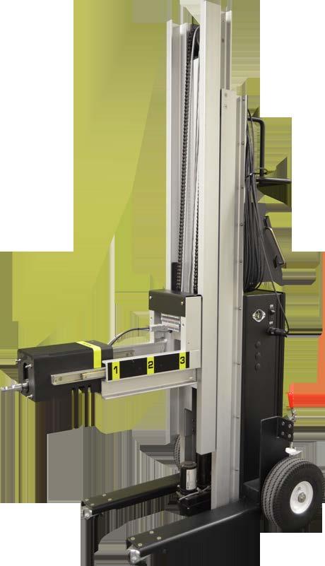
11 STEPS FOR PROPER RECEIVING: 1) Inspect the pallet and inorac2 for mishandling. Make notations of any damage to the packaging. Examples of damage include punctures, crushes, scrapes, broken boards, & other visible damage. 2) In rare cases of total loss, the receiver may refuse the entire shipment. In such a case, do not unpack the equipment and conclude the inspection with a notation of the date and the specific reason for refusal. STEPS FOR PROPER UNPACKING AND INSPECTION: The inorac2 shall arrive as shown in the picture below. 1) Remove overall shrink wrap. 2) Cut (3) banding straps holding inorac2 on pallet. 3) Remove shrink wrap and shipping bracket from inorac2 motor carriage. 4) Slowly stand inorac2 upright, allowing motor carriage to slide forward, and remove from pallet. 5) Remove bubble wrap from inorac2 handle. 6) Remove shrink wrap from inorac2 boom. 7) Inspect the contents of every accessory in the shipment. Make notations of any shortage (the absence of content listed on the shipment packing list) or damage including breakage, chipped edges, deep scratches or scuffs. To be considered valid, these notations must reference the quantity, identity and damage or shortage specifics of all affected content. inolect must be notified within 48 hours of receipt of any damaged or missing accessories. 8) Move the inorac2 to the final location for use. (for multiple units, it may be advantageous to stage the devices in a single location to expedite commissioning activities) 11

12 STEPS FOR MOVING AND LIFTING: Method of Lifting 1: Optional Lifting Eyes for moving with crank or hoist. Optional Lifting Eyes 12


13 Method of Lifting 2: Manual lifting using specific Lift Points. Lift Point Lift Point Lift Point 13
14 4.0 Circuit Breaker Racking Instructions 1. Connect the required accessories to the inorac2 by following the accessory instructions. 2. Connect 120 VAC (230 VAC for European models) to the inorac2 via the receptacle on the side of the control enclosure. 3. Turn on the inorac2 by placing the ON/OFF switch on the side of the control enclosure into the ON position. 4. Start the inorac2 by pressing the Racking Unit Control button on the Operator Panel. 5. Ensure the inorac2 is not connected to a circuit breaker. Ensure the inorac2 is free to operate all accessories. Follow the Operator Panel instructions for calibrating the inorac2. 6. Select the operation to be performed, Rack Breaker on the Operator Panel. 7. Follow the Operator Panel instructions for selecting the breaker to be racked. 8. Confirm the object circuit breaker is open position via a visual inspection. 9. Adjust the inorac2 height to the level of the circuit breaker racking mechanism via the Raise and Lower buttons on the Operator Panel. 10. Align the inorac2 breaker connection accessory to the circuit breaker racking mechanism via the Jog CW and Jog CCW buttons on the Operator Panel. 11. Connect the inorac2 to the circuit breaker racking mechanism. 12. Set the brakes on the inorac2. 14
15 13. Move to a safe location outside the arc flash hazard boundary with the Operator Panel. 14. Follow the Operator Panel instructions for racking the circuit breaker. 15. Disconnect the inorac2 from the circuit breaker. 16. Turn off the inorac2 by placing the ON/OFF switch on the side of the control enclosure into the OFF position. 4.1 Pushbutton Operation Instructions 1. Connect the required accessories to the inorac2 by following the accessory instructions. 2. Connect 120 VAC (230 VAC for European models) to the inorac2 via the receptacle on the side of the control enclosure. 3. Turn on the inorac2 by placing the ON/OFF switch on the side of the control enclosure into the ON position. 4. Start the inorac2 by pressing the Racking Unit Control button on the Operator Panel. 5. Ensure the inorac2 is not connected to a circuit breaker. Ensure the inorac2 is free to operate all accessories. Follow the Operator Panel instructions for calibrating the inorac2. 6. Select the operation to be performed, Operate Pushbutton on the Operator Panel. 7. Adjust the inorac2 height to the level of the pushbutton to press via the Raise and Lower buttons on the Operator Panel. 8. Place the inorac2 1/2 from the pushbutton to press. 15
16 9. Set the brakes on the inorac Move to a safe location outside the arc flash hazard boundary with the Operator Panel. 11. Follow the Operator Panel instructions for pressing the pushbutton. 12. Turn off the inorac2 by placing the ON/OFF switch on the side of the control enclosure into the OFF position. 4.2 User Setup Instructions 1. Connect 120 VAC (230 VAC for European models) to the inorac2 via the receptacle on the side of the control enclosure. 2. Turn on the inorac2 by placing the ON/OFF switch on the side of the control enclosure into the ON position. 3. Start the inorac2 by pressing the Racking Unit Control button on the Operator Panel. 4. Ensure the inorac2 is not connected to a circuit breaker. Ensure the inorac2 is free to operate all accessories. Follow the Operator Panel instructions for calibrating the inorac2. 5. Select the operation to be performed, BUTTON SETUP on the Operator Panel. 6. A Logon screen will appear. The User is Admin. The Password is Log in. 7. Re-select the operation to be performed, BUTTON SETUP on the Operator Panel. 8. Press the text on the respective button to edit the text. An editor will appear. Type the desired text via the on screen keyboard. Hit the return key to accept. a. The labels for each of the eleven screens can be changed. 16
17 9. Press the number next to the respective button to edit the pointer. An editor will appear. Type the desired number via the on screen keyboard. Hit the return key to accept. a. This number is the pointer to the specific breaker profile in the master breaker list. Contact inolect for the pointer for your specific breakers. b. Improper pointers will likely result in improper and unsafe breaker racking operation. 10. Press the OK, and NO buttons to show or not show the respective button. 11. Follow the on screen instructions for saving the user setup. 4.3 PROFILE BREAKER Instructions This button allows for new breaker profiles to be created. Contact inolect for instructions. 17
18 4.4 Calibrate Accessory Actuators Instructions 1. Connect the required accessories to the inorac2. 2. Connect 120 VAC (230 VAC for European models) to the inorac2 via the receptacle on the side of the control enclosure. 3. Turn on the inorac2 by placing the ON/OFF switch on the side of the control enclosure into the ON position. 4. Start the inorac2 by pressing the Racking Unit Control button on the Operator Panel. 5. Ensure the inorac2 is not connected to a circuit breaker. Ensure the inorac2 is free to operate all accessories. 6. Select CALIBRATE ACCESSORY ACTUATORS on the Operator Panel. 7. Acknowledge each of the three checklist questions by selecting the NO buttons to the right of each item. After all three checklist items are acknowledged, the CALIBRATE button will display. 8. Select the CALIBRATE button. CALIBRATING will be displayed for approximately 45 seconds. 9. When CAILBRATION COMPLETE is displayed, the actuator of the connected accessory s position reference is calibrated and the accessory is ready for use. 18
19 5.0 Maintenance The inorac2 is designed to be a very low maintenance device. However as with all equipment it should be checked for proper operation and condition on a periodic basis. The following maintenance items should be performed on a periodic basis. Power up the inorac2 to operate a circuit breaker without connecting the inorac2 to an actual circuit breaker. Check that all hardware and fasteners are in good condition and check for tightness. Lubricate actuator lift chain. Mobilgrease 28 lubricant is recommended. Lubricate wheels and casters. Mobilgrease 28 lubricant is recommended. Check actuator lift track slides for hardware tightness and for smooth, free operation. Lubrication is not required. Check motor base slides for hardware tightness and for smooth, free operation. Lubrication is not required. Check linear springs for wear or damage. Check hardware for tightness. Check brakes for loose or damaged hardware. Check brakes for proper adjustment. Check the cable to the operators panel touch screen for wear or damage. Inspect the control components in the control box for loose or damaged items and for loose or damaged wiring. The first maintenance period should be 6 months after receiving inorac2 and then continue at 12 month intervals. 19

20 5.1 Alarms and Troubleshooting Engage Failure Alarm Problem: The Unit has failed to engage the breaker racking screw. Solution: Confirm accessory is properly connected to the circuit breaker and retry. 20

21 Overturns Alarm Problem: The unit racked past the number of turns without recognizing the required torque. Solution: Check the position and retry racking procedure. 21
22 Over-torque Alarm Problem: The unit experienced over-torque conditions. Solution: Disconnect the unit and check the switchgear and breakers for mechanical obstructions. 22
23 6.0 Spare Parts List Part Number Description Receptacle Control Power Transformer Rectifier On/Off Switch Fuse Holder A Fuse Cover Caster Wheels Linear Spring Brake Toggle 23
24 Touch Panel Variable Frequency Drive Programmable Logic Controller Analog Input Signal Board CPU Memory Card Terminal Block Point Terminal Plug Point Terminal Plug Point Terminal Plug 24
25 Designed and Manufactured by inolect, LLC Copyright North Interstate Dr. Baton Rouge, LA For questions or 24-hour assistance, please call (225) Reproduction, adaptation or translation without the written permission of inolect, LLC is strictly prohibited. 25
MTS Criterion Series 40
 MTS Criterion Series 40 Manual Title Lifting and Moving Additional Instructions Information be certain. 100-231-444 C Copyright information Trademark information Proprietary information Software validation
OPERATOR S MANUAL Model 56A Prefeed / Dereeler
 110 Fairgrounds Drive P.O. Box 188 Manlius, NY 13104-0188 USA 315.682.9176 FAX: 315.682.9160 OPERATOR S MANUAL Model 56A Prefeed / Dereeler PRODUCTION WIRE PROCESSING EQUIPMENT Website: www.carpentermfg.com
TRUCK HOIST A TOP Safety Requirements Please Read!
 TRUCK HOIST A TOP Safety Requirements Please Read! Please thoroughly read and understand these instructions before installing your Hoist-A-Top and before lifting your top. When installing the Hoist-A-Top
Maintenance Bypass Breaker Cabinet Series Configuration 5. Installation and Operation Manual
 Maintenance Bypass Breaker Cabinet 90881 Series Configuration 5 Installation and Operation Manual 03/13/2012 2 755-00084-C5 R03 Copyright 2012 C&C Power, Inc. All rights reserved. C&C Power, Inc. 395 Mission
XBDM-HW63. 63A Model. User & Installation Manual Xtreme Power Conversion Corporation. All rights reserved.
 XBDM-HW63 63A Model User & Installation Manual www.xpcc.com 2016. All rights reserved. (Rev 3/02/16) Table of Contents Introduction...3 Product Overview... 3 Installation and Operation...4 Inspection...4
MTTC User Manual. Innovative Technology for a Connected World. General Description. Specifications and features
 Innovative Technology for a Connected World MTTC-1410 General Description The MTTC-1410 Thermoelectric is a precision instrument that utilizes Pulse Width Modulation (PWM) control technology to provide
Festoon Manual Heavy Duty C-Track
 Festoon Manual Heavy Duty C-Track 966300.3 Heavy Duty C-Track Manual CONDUCTIX INCORPORATED The technical data and images which appear in this manual are for informational purposes only. NO WARRANTIES,
ISIMET. E Series Enclosure. Custom Assemblies Installation, Maintenance, and Operation Instructions
 ISIMET E Series Enclosure Custom Assemblies Installation, Maintenance, and Operation Instructions The Custom Assembled E-Series Enclosures is pre-assembled and pre-wired enclosure intended for use with
Maintenance Bypass Breaker Cabinet Series Configuration 2. Installation and Operation Manual
 Maintenance Bypass Breaker Cabinet 90881 Series Configuration 2 Installation and Operation Manual 03/13/2012 2 755-00084-C2 R03 Copyright 2012 C&C Power, Inc. All rights reserved. C&C Power, Inc. 395 Mission
Car and Counterweight Frames
 Car and Counterweight Frames CAR FRAME (SLING) AND PLATFORM COUNTERWEIGHT FRAME Every attempt has been made to ensure that this documentation is as accurate and up-to-date as possible. However, Vertical
Sby SR Instruments, Inc.
 Part No.: MAN947IFS_170629 Page 1 of 12 Sby SR Instruments, Inc. SRV947IFS REMOTE DISPLAY PLATFORM SCALE Operating and Service Manual Part No.: MAN947IFS_170629 Page 2 of 12 TABLE OF CONTENTS TABLE OF
1-300 SERIES Endover Rotator Operator s Manual for Morse End-Over-End Drum Rotators Series
 Contents Page Receiving Procedures.................... 1 Warranty............................. 1 Safety Information..................... 1-2 Machine Description................... 3 Operating Instructions....................
INSTALLATION MANUAL SURFACE-MOUNTED HEADWALL
 INSTALLATION MANUAL SURFACE-MOUNTED HEADWALL Model # Series 7200-S Top Mounting Plate Electrical Junction Box Located Behind Removable Upper Panel Medical Gas Connections Lower Mounting Plate OVERVIEW
Manual Rotary Heat Sealers. Type: F108TX. List of content : Introduction 2. General description 3. Application 4. Safety precautions 5
 Manual Rotary Heat Sealers Type: F108TX List of content : Page: Introduction 2 General description 3 Application 4 Safety precautions 5 Transport and storage 6 Installation 7 First Set-up 8 Connection
Quick-Start Operating Guide Document No Exhaust Fume Hood Copyright 2010 Terra Universal Inc. All rights reserved. Revised September 2010
 Document No. 1800-65 Exhaust Fume Hood Copyright 2010 Terra Universal Inc. All rights reserved. Revised September 2010 Terra Universal, Inc. TerraUniversal.com 800 S. Raymond Ave. Fullerton, CA 92831 TEL:
Gerber. Scientific Products. Dear Gerber Sabre Customer:
 Gerber Scientific Products 151 Batson Drive, Manchester, CT 06040 (860) 643-1515 Dear Gerber Sabre Customer: Thank you for purchasing the Sabre, Gerber Scientific Products advanced, high-speed, three-dimensional
6 Closet light. Model Due to continuing improvements, actual product may differ slightly from the product described herein.
 6 Closet light Model 95792 Assembly And Operation Instructions Due to continuing improvements, actual product may differ slightly from the product described herein. 3491 Mission Oaks Blvd., Camarillo,
J60 Lithium Ion UPS 350VA Model User & Installation Manual Xtreme Power Conversion Corporation. All rights reserved.
 J60 Lithium Ion UPS 350VA Model User & Installation Manual www.xpcc.com 2018. All rights reserved. (Rev 5/24/18) Table of Contents Package Contents...3 Product Introduction...3 Product Overview...3 Installation
MODEL 185R Kontrol-Karrier Operator s Manual for Morse Kontrol-Karrier
 Contents Page Receiving Procedures.................... 1 Warranty............................. 1 Safety Information..................... 1-2 Machine Description................... 3 Operating Instructions....................
Operator s Manual for Morse Heavy-Duty Kontrol-Karrier with 3-Piece Drum Holder
 CONTENTS Page Receiving Procedures.................... 1 Warranty............................. 1 Safety Information..................... 1-2 Machine Description................... 3 Operating Instructions....................
Sageon Site Monitor (SSM) Application Note
 Application Note") Sageon Site Monitor (SSM) Application Note AN103-4012-00, Issue 3 UNIPOWER, LLC 3900 Coral Ridge Drive Coral Springs, FL 33065 Phone: +1-954-346-2442 Toll Free: 1-800-440-3504 Web site http://www.unipowerco.com
Sageon Site Monitor (SSM) Application Note AN103-4012-00, Issue 3 UNIPOWER, LLC 3900 Coral Ridge Drive Coral Springs, FL 33065 Phone: +1-954-346-2442 Toll Free: 1-800-440-3504 Web site http://www.unipowerco.com
FORM HEADWALL. FORM HEADWALL (floor mount) (floor mount) Installation Manual
 (floor mount) Installation Manual") FORM HEADWALL (floor mount) Installation Manual FORM HEADWALL (floor mount) OVERVIEW The Form is a UL-listed configurable headwall system. This system includes multiple horizontal equipment channels integrated
FORM HEADWALL (floor mount) Installation Manual FORM HEADWALL (floor mount) OVERVIEW The Form is a UL-listed configurable headwall system. This system includes multiple horizontal equipment channels integrated
78-RK VARIABLE SPEED HEAVY DUTY VIBRATOR OPERATING MANUAL
 78-RK VARIABLE SPEED HEAVY DUTY VIBRATOR OPERATING MANUAL IMPORTANT INSTRUCTIONS WARNING! FOR YOUR SAFETY PLEASE READ INSTRUCTIONS BEFORE OPERATING TOOL & WEAR EYE PROTECTION FD.08/2009 THANK YOU FOR PURCHASING
ODYSSEY FLOOR MODEL. Owner s Manual. O-6400-F shown rev 118
 Owner s Manual ODYSSEY FLOOR MODEL O-6400-F shown 67-1455 rev 118 3730 E. Southern Avenue, Phoenix, AZ 85040 USA 800-778-8779 Workhorseproducts.com 1 Table of Contents I. Introduction & Safety Information.
Installation Guide Document No Transaction Windows Copyright 2017 Terra Universal Inc. All rights reserved. Revised October 2017
 Installation Guide Document No. 1788-01 Copyright 2017 Terra Universal Inc. All rights reserved. Revised October 2017 Terra Universal, Inc. TerraUniversal.com 800 S. Raymond Ave. Fullerton, CA 92831 TEL:
FORM HEADWALL. FORM HEADWALL (floating) (floating) Installation Manual
 (floating) Installation Manual") FORM HEADWALL (floating) Installation Manual FORM HEADWALL (floating) OVERVIEW The Form is a UL-listed configurable headwall system. This system includes multiple horizontal equipment channels integrated
FORM HEADWALL (floating) Installation Manual FORM HEADWALL (floating) OVERVIEW The Form is a UL-listed configurable headwall system. This system includes multiple horizontal equipment channels integrated
C60 Standby UPS. 800VA Models. User & Installation Manual Xtreme Power Conversion Corporation. All rights reserved.
 For more information, visit www.247technology.com/on-line-ups/c60-standby-ups C60 Standby UPS 800VA Models User & Installation Manual 2015. All rights reserved. (Rev 6/23/15) Table of Contents Package
Installation and Operation Manual
 Installation and Operation Manual Maintenance Bypass Panel Model: SU2030KMBP Tripp Lite follows a policy of continuous improvement. Product specifications are subject to change without notice. 1111 West
OPTO BRANCH 6 RJ45. user manual. ELATION OPTO BRANCH 6 RJ45 user manual
 OPTO BRANCH 6 RJ45 user manual ELATION OPTO BRANCH 6 RJ45 user manual 2015 ELATION PROFESSIONAL all rights reserved. Information, specifications, diagrams, images, and instructions herein are subject to
GEK B Instructions. Test Cabinet. for Power/Vac Vacuum Circuit Breakers
 g GEK 105263B Instructions Test Cabinet for Power/Vac Vacuum Circuit Breakers Power/Vac Test Cabinet Table of Contents Section 1. Introduction 1-1 Safety... 3 1-2 Maintenance... 3 Section 2. Receiving,
Elevation Station MODEL: ES.02-16
 Owner s Manual Elevation Station MODEL: ES.02-16 Southworth Products Corp P.O. Box 1380, Portland, ME 04104-1380 Phone 800-743-1000 FAX 207-797-4734 www.southworthproducts.com service@southworthproducts.com
TL-600 MOBILE PHASE HEATER
 TL-600 MOBILE PHASE HEATER INSTRUCTION MANUAL Timberline Instruments, Inc. 1880 S. Flatiron Ct., Unit I Boulder, Colorado 80301 Ph: (303) 440-8779 Fx: (303) 440-8786 info@timberlineinstruments.com www.timberlineinstruments.com
LIGHT CONTROLLER LC 500
 LIGHT CONTROLLER LC 500 Manual and User Guide Please read this manual before operating this product PSI, spol. s r. o., Drásov 470, 664 24 Drásov, Czech Republic FAX: +420 511 440 901, TEL: +420 511 440
MiT. MOVING image TECHNOLOGIES INSTRUCTIONS FOR INSTALLATION, OPERATION, AND MAINTENANCE. MPL Digital Pedestal. Manual Version 0.2
 MiT MOVING image TECHNOLOGIES INSTRUCTIONS FOR INSTALLATION, OPERATION, AND MAINTENANCE OF MPL Digital Pedestal Manual Version 0.2 MOVING image TECHNOLOGIES, LLC. 17760 Newhope St. Fountain Valley, CA
POWER PINNER BENCH HAND WELDER 7250 OPERATOR S MANUAL
 POWER PINNER BENCH HAND WELDER 7250 OPERATOR S MANUAL Copyright: November 20, 2018 Revised: Serial No. Gripnail Corporation An Employee Owned Company 97 Dexter Road East Providence, Rhode Island 02914-2045
Operator s Manual for Morse Kontrol-Karrier with Spark Resistant Parts and Air Power Tilt
 Contents Page Receiving Procedures.................... 1 Warranty............................. 1 Safety Information..................... 1-2 Machine Description................... 2 Assembly Instructions..................
Safety Precautions. 3. Cabinet Assembly 4. Operating buttons / functions.5-6. Machine Operation
 USER MANUAL Contents Safety Precautions. 3 Cabinet Assembly 4 Operating buttons / functions.5-6 Machine Operation...7-11 Convert from Inches to Millimeters / Millimeters to Inches.. 7 Programming in Manual
WARNING ELECTRIC PALLET TRUCK EPT Revised A company dedicated to solving ergonomic and material handling problems since 1955.
 VESTIL MANUFACTURING CORPORATION 2999 North Wayne Street, P.O. Box 507 Angola, Indiana 46703 USA Phone (260) 665-7586 Fax (260) 665-1339 sales@vestil.com www.vestil.com SAFETY INSTRUCTIONS & OPERATING
Xxxxx Xxxxxx OM-CP-TEMP101A. Temperature Data Logger with 10 year battery life INSTRUCTION SHEET MQS5026/0117
 Xxxxx Xxxxxx Temperature Data Logger with 10 year battery life INSTRUCTION SHEET MQS5026/0117 Shop online at omega.com SM e-mail: info@omega.com For latest product manuals: www.omegamanual.info Product
LOAD RAMP 1000 LB. CAPACITY
 LOAD RAMP 1000 LB. CAPACITY 55424 ASSEMBLY AND OPERATING INSTRUCTIONS Safely roll Dirt Bikes and more into your Pickup! 3491 Mission Oaks Blvd., Camarillo, CA 93011 Visit our Web site at http://www.harborfreight.com
VI PARTS LIST. , ELECTRIC FRYER PARTS LIST ITEM DESCRIPTION MODELS PART # 10x x24
 VI PARTS LIST ORDERING PARTS Parts may be ordered by part number by calling Keating at 1-800-KEATING or your service company. You may also order online at Keating s part store, www.keatingofchicago.com.
V-series 1. How to get started
 1 How to get started 08-2014 Contents 1. Preface...3 2. Change record...4 3. Introduction...5 3.1 Welcome...5 3.2 SoC, ROHS...6 3.3 Statement of Conformity...7 4. General Information... 8 4.1 Where to
3601 E. 34th St. Tucson, AZ USA Tel Fax Web:
 Equipment Type: Model: Electrical Requirements: Frequency: Manual Revision Date: Air Flow Sound Level Fume Hood FUME HOOD 110V 60 Hz February 15, 2018 1175-1470 cfm 65 dba Contents Warranty PAGE ii 1.0
Gerber Scientific Products
 Page 1 of 9 Sabre Series Router Pre-Installation Checklist Gerber FastFact # 5003 Supplied by: Gerber Service Last Modified: June 28, 2012 Summary: This document provides the Pre-Installation for your
Power Distribution Module Replacement Instructions
 Power Distribution Module Replacement Instructions Introduction This publication describes the replacement procedure for the power distribution module (PDM) in 4100U and 4100ES Fire Alarm Control Panels
Assembly Instructions Legacy Basic Acoustical Shell
 Assembly Instructions Legacy Basic Acoustical Shell Contents Important User Information...........................2 Safety Precautions.................................3 Required Tools.....................................3
TeraFrame HD Cabinet System Supplemental Installation Guide
 TeraFrame HD Cabinet System Supplemental Installation Guide 800-834-4969 techsupport@chatsworth.com www.chatsworth.com 2010 Chatsworth Products, Inc. All rights reserved. CPI, TeraFrame and MegaFrame are
4 rotary milling table
 4 rotary milling table Model 97208 Set up And Operating Instructions Diagrams within this manual may not be drawn proportionally. Due to continuing improvements, actual product may differ slightly from
Operator s Manual for Morse Mobile-Karrier for 55-Gallon Plastic or Steel Drum
 Contents Page Receiving Procedures.................... 1 Warranty............................. 1 Safety Information..................... 1-2 Machine Description................... 3 Operating Instructions....................
APC Step-Down Transformer. Models: AP9626, AP9627, and AP9628
 User Manual English APC Step-Down Transformer Models: AP9626, AP9627, and AP9628 990-7820F 06/2006 Introduction Introduction The APC step-down transformers are used to convert a higher input voltage (208-200
Glide-Line Heavy Duty Lift Locate Unit (HLLU)
") V1.0 Glide-Line Heavy Duty Lift Locate Unit (HLLU) Installation & Maintenance Manual Easy Flexible Precise Fast i V1.0 Manual Information Throughout this manual are the following information blocks indicated
V1.0 Glide-Line Heavy Duty Lift Locate Unit (HLLU) Installation & Maintenance Manual Easy Flexible Precise Fast i V1.0 Manual Information Throughout this manual are the following information blocks indicated
MODELS MB1K-1, MB1K-2 MB2K-1, MB2K-2 MB3K-1, MB3K-2
 FALCON ELECTRIC INC. OWNER S MANUAL SG Series Maintenance Bypass Option 1KVA 3KVA MODELS MB1K-1, MB1K-2 MB2K-1, MB2K-2 MB3K-1, MB3K-2 OM48030 Rev. B 01/17/03 FALCON Electric Inc., 5106 Azusa Canyon Road,
Wenger Corporation 2011 Printed in USA 02/11 Part #185A462-01
 User Instructions Diva Air Transporter contents Introduction.......................................2 General......................................2 Manufacturer.................................2 European
VISE MOUNTED. Model 97359
 VISE MOUNTED Small English wheel Model 97359 Set up And Operating Instructions Diagrams within this manual may not be drawn proportionally. Due to continuing improvements, actual product may differ slightly
Table of contents. 1. Introduction
 2 Year Warranty Table of contents 1. Introduction 1-1. Transportation 1-2. Preliminary steps 1-3. Initial setup 1-4. Important safety instructions 1-5. Maintenance, service and faults 2. Operation 2.1
MD Power Supply -48Vdc +Bias Tee
 215988-001MD Power Supply -48Vdc +Bias Tee Operation and Maintenance Manual Mitec Telecom Inc. Designers and manufacturers of telecom and wireless products 9000 Trans Canada, Pointe-Claire, Quebec, Canada
Loading Arm Installation, Maintenance & Safety Manual
 Loading Arm Installation, Maintenance & Safety Manual Version Loading Arm Hot Line: 1-800-547-9393 Dear OPW Customer: Thank you for selecting OPW Engineered Systems, Inc. ("OPW"), and giving us the opportunity
DMX-BRANCH/4. user manual. ELATION DMX-BRANCH/4 user manual
 DMX-BRANCH/4 user manual ELATION DMX-BRANCH/4 user manual 2016 ELATION PROFESSIONAL all rights reserved. Information, specifications, diagrams, images, and instructions herein are subject to change without
PORTABLE CHAIR SCALES BEAM and DIGITAL TYPES MODELS 475, 4751, 6475, 6475k and 6475KGEU
 PORTABLE CHAIR SCALES BEAM and DIGITAL TYPES MODELS 475, 4751, 6475, 6475k and 6475KGEU CARDINAL SCALE MFG. CO. 0033-M128-O1 Rev H PO Box 151 Webb City, MO 64870 10/08 Ph: 417-673-4631 Fax: 417-673-5001
92831 TEL: (714) FAX:
 FAX:") Document No. 1800-18 Copyright 2010 Terra Universal Inc. All rights reserved. Rev. Sept. 2010 Terra Universal, Inc. TerraUniversal.com 800 S. Raymond Ave. Fullerton, CA 92831 TEL: (714) 578-6000 FAX: (714)
Document No. 1800-18 Copyright 2010 Terra Universal Inc. All rights reserved. Rev. Sept. 2010 Terra Universal, Inc. TerraUniversal.com 800 S. Raymond Ave. Fullerton, CA 92831 TEL: (714) 578-6000 FAX: (714)
PLEASE SAVE THESE INSTRUCTIONS FOR FUTURE USE
 GF6590BH-1 PATRIOT LIBERTY HALF NO-GAP HEAD RAILS: INSTALLATION & OPERATION INSTRUCTIONS FOR PATRIOT BED PLEASE SAVE THESE INSTRUCTIONS FOR FUTURE USE Info: The most current version of these instructions
Drive Services Policy and Warranty Information
 Project: ISO doc: P 1206121 Michael Vallier Dan Reshel Dec 12, 2013 C 1 / 10 This document is a supplement to the ABB Inc. General Terms and Conditions of Sale (publication number ABBGTC073101). This document
Operation & Service Manual METTLER TOLEDO PFA220. Operation & Service Manual
 Operation & Service Manual METTLER TOLEDO PFA220 Series Floor Scale Operation & Service Manual Contents 1 Safety notice... 1 2 Introduction... 2 2.1 General... 2 2.2 Standard Sizes and Capacities...
INSTALLATION AND OPERATION MANUAL
 PLEASE READ THE ENTIRE CONTENTS OF THIS MANUAL PRIOR TO INSTALLATION AND OPERATION. BY PROCEEDING YOU AGREE THAT YOU FULLY UNDERSTAND AND COMPREHEND THE FULL CONTENTS OF THIS MANUAL. FORWARD THIS MANUAL
CR-3000 Car Rotator Capacity 3,000 lbs Installation Manual 2016 Mar
 Car Rotator Capacity 3,000 lbs Installation Manual 2016 Mar INDEX 1. OWNER / USER RESPONSIBILITIES---------------------------------------- PAGE 3 2. SAFETY PROCEDURES---------------------------------------------------------
500XL Childbearing Bed OPERATIONS MANUAL. For Parts or Technical Assistance
 500XL Childbearing Bed OPERATIONS MANUAL For Parts or Technical Assistance 1 800 327 0770 Table of Contents Introduction..................................................................... 2 Specifications....................................................................
XSTi Standby UPS. 400VA, 600VA, 800VA Models. User & Installation Manual
 XSTi Standby UPS 400VA, 600VA, 800VA Models User & Installation Manual www.xpcc.com 2015. All rights reserved. (Rev 12/14/15) Table of Contents Package Contents... 3 Product Introduction... 3 Product Overview...
Miniglaze/2. Owner & Operator's Manual PORCELAIN STAINING AND GLAZING FURNACE. Model No: Voltage: V 50/60Hz V 50/60Hz
 Miniglaze/2 PORCELAIN STAINING AND GLAZING FURNACE Owner & Operator's Manual Model No: Voltage: 9490950 115V 50/60Hz 9490952 220V 50/60Hz DESCRIPTION PAGE Safety...2 Features...3 Furnace Description...4
HDI 2200 Choke Position Indicator
 HDI 2200 Choke Position Indicator Operations and Maintenance Manual Rev. 1203 www.houstondigital.com email: sales@houstondigital.com or service@houstondigital.com TABLE OF CONTENTS SECTION 1 SECTION 2
V 2.0 ASSEMBLY GUIDE. TS Platform Scale Series 2
 V 2.0 ASSEMBLY GUIDE Series 2 TABLE OF CONTENTS OVERVIEW General Specifications...1 Cautions and Disclaimers...1 Contents of Kit...1 Tools Required For Assembly...2 Time Required to Assemble...2 ASSEMBLING
Dandy Leveler UDLV-150 & UDLV-500 (New Style)
") Owner s Manual Dandy Leveler UDLV-150 & UDLV-500 (New Style) Model # Serial # Southworth Products Corp P.O. Box 1380/Portland, Maine 04104-1380 Phone 800-743-1000 FAX 207-797-4734 www.southworthproducts.com
Owner s Manual Dandy Leveler UDLV-150 & UDLV-500 (New Style) Model # Serial # Southworth Products Corp P.O. Box 1380/Portland, Maine 04104-1380 Phone 800-743-1000 FAX 207-797-4734 www.southworthproducts.com
You will probably need to perform this procedure in the loading dock area of the building. A fork lift or chain hoist may be needed.
 This chapter contains the following sections: Unpacking a Cisco R-Series Rack, page Remove the Packaging, page Accessories, page 3 Safety Guidelines, page 4 Removing the Cisco Cisco R4262 Rack from the
General Guidelines. Instructions for Part # WP Safety. It is the user s responsibility to read and follow all instructions.
 General Guidelines It is the user s responsibility to read and follow all instructions. Instructions for Part # WP-48-1000 Keep these instructions with the product at all times and review before each use.
Symmetra PX kw 208 V. Receiving and Unpacking 08/2015.
 Symmetra PX 10 40 kw 208 V Receiving and Unpacking 08/2015 www.schneider-electric.com Legal Information The Schneider Electric brand and any registered trademarks of Schneider Electric Industries SAS referred
CR-SERIES CARPET POLES INSTRUCTION MANUAL
 VESTIL MANUFACTURING CORP. 2999 North Wayne Street, P.O. Box 507, Angola, IN 46703 Telephone: (260) 665-7586 -or- Toll Free (800) 348-0868 Fax: (260) 665-339 www.vestilmfg.com e-mail: sales@vestil.com
Owner s Manual & Safety Instructions
 Owner s Manual & Safety Instructions Save This Manual Keep this manual for the safety warnings and precautions, assembly, operating, inspection, maintenance and cleaning procedures. Write the product s
Mechanical Post Lift. Owner s Manual
 Table Owner s Manual Model: Serial Number: Date placed in service: Presto ECOA Lifts 50 Commerce Way, Norton, MA 02766 Phone: 800.343.9322 Fax: 888.788.6496 www.prestolifts.com Email: service@prestolifts.com
GF6580BH-1 PATRIOT LIBERTY QUARTER RAILS:
 GF6580BH-1 PATRIOT LIBERTY QUARTER RAILS: INSTALLATION & OPERATION INSTRUCTIONS FOR PATRIOT BED PLEASE SAVE THESE INSTRUCTIONS FOR FUTURE USE Info: The most current version of these instructions can be
Installation Manual. Omnicell. Model: 9102 FB by Fairbanks Scales, Inc. Revision 4 08/16 All rights reserved
 Installation Manual Omnicell Model: 9102 FB 51175 2007-2016 by Fairbanks Scales, Inc. Revision 4 08/16 All rights reserved Amendment Record Omnicell 9102 FB Installation Manual DOCUMENT 51175 Manufactured
Symmetra PX 160 Classic Battery Cabinet
 Symmetra PX 160 Classic Battery Cabinet Receiving and Unpacking 04/2015 www.schneider-electric.com Legal Information The Schneider Electric brand and any registered trademarks of Schneider Electric Industries
Drag Chain Conveyor Installation and Operation Manual
 Drag Chain Conveyor Installation and Operation Manual Material Handling Equipment Sales, Incorporated 310 S. Section Line Rd Delaware, OH 43015 Phone: (989) 430-4005 Fax: (740) 363-9004 WARRANTY MATERIAL
$250 Capacity ChangeMaker Operator s Manual
 $250 Capacity ChangeMaker Operator s Manual Rev. 2017.11.17 1 INTRODUCTION Congratulations on the purchase of your new ChangeMaker. This ChangeMaker has been designed to give you many years of dependable
Model 10A. Model 20A. Operating Manual. ECG Simulator. ECG / Arrythmia Simulator
 Model 10A ECG Simulator Model 20A ECG / Arrythmia Simulator Operating Manual Model 10A / 20A Patient Simulators Operating Manual 2006-2014 Datrend Systems Inc. Unit 130-4020 Viking Way Richmond, BC CANADA
Precision Automatic Vacuum Control (PAVC+)
") USER GUIDE UGE105-1216 www.conairgroup.com Precision Automatic Vacuum Control (PAVC+) Corporate Office: 724.584.5500 l Instant Access 24/7 (Parts and Service): 800.458.1960 l Parts and Service: 814.437.6861
USER GUIDE UGE105-1216 www.conairgroup.com Precision Automatic Vacuum Control (PAVC+) Corporate Office: 724.584.5500 l Instant Access 24/7 (Parts and Service): 800.458.1960 l Parts and Service: 814.437.6861
PalletPal Low Profile Disc Turntable
 OWNER S MANUAL PalletPal Low Profile Disc Turntable Model # Serial # Date placed in Service SOUTHWORTH PRODUCTS CORP P.O. Box 1380 Portland, ME 04104-1380 Telephone: (207) 878-0700 or (800) 743-1000 Fax:
Installation & Maintenance Manual
 Installation & Maintenance Manual Model: Live Roller Spur Direct Current (RLSDC) WWW.BASTIANSOLUTIONS.COM 888.725.3194 1 TABLE OF CONTENTS WARNING!... 3 INTRODUCTION... 4 APPLICATIONS... 4 RECEIVING AND
Model # 815P-VCA3. 3/31/2011 Page 1 of 10
 Model # 815P-VCA3 3/31/2011 Page 1 of 10 3/31/2011 Page 2 of 10 1675 Locust Street Red Bud, IL 62278 Phone: 618-282-8200 Fax: 618-282-8202 WARRANTY & TERMS WARRANTY: 5 Year Limited Warranty on Thermoplastic
Edge-of-Dock Leveler 'BA' - 'BX' Series. Owner s Manual and Installation Instructions
 Edge-of-Dock Leveler 'BA' - 'BX' Series Owner s Manual and Installation Instructions A Message to Aaron-Bradley Edge-of-Dock Owners and Operators Edge-of-Docks are specialized equipment with unique operating
10810 W. LITTLE YORK RD. #130 - HOUSTON, TX VOICE (713) FAX (713) web: IMPORTANT!!!
 FAX (713) web: IMPORTANT!!!") 10810 W. LITTLE YORK RD. #130 - HOUSTON, TX 77041-4051 VOICE (713) 973-6905 - FAX (713) 973-9352 web: www.twrlighting.com IMPORTANT!!! PLEASE TAKE THE TIME TO FILL OUT THIS FORM COMPLETELY. FILE IT IN
10810 W. LITTLE YORK RD. #130 - HOUSTON, TX 77041-4051 VOICE (713) 973-6905 - FAX (713) 973-9352 web: www.twrlighting.com IMPORTANT!!! PLEASE TAKE THE TIME TO FILL OUT THIS FORM COMPLETELY. FILE IT IN
Bravo Platform Unpacking Guide
 This guide describes how to unpack the Bravo device from the shipping carton. Depending on the order, the shipment can include additional packages for the Bravo utilities, pipetting head, computer, and
In-Wall Slide-out OEM INSTALLATION MANUAL
 In-Wall Slide-out OEM INSTALLATION MANUAL TABLE OF CONTENTS System and Safety Information 2 In-Wall Slide-Out Chassis Specification 3 6.1.1 Slide-Out Configurations 3 In-Wall Slide-Outs 3 Recommended Wall
Model TS-100 Tubing Spider Installation, Operation, Service and Parts Book Manual
 Model TS-100 Tubing Spider Installation, Operation, Service and Parts Book Manual WPI WELLKIN Inc. 8401 Industrial Dr. Pearland, TX 77584 PH: (281) 992-2064 FX: (281) 992-2076 E-mail: sales@wpiwellkin.com
OPERATOR S MANUAL Model 27G Rotary Collet Magnet Wire Stripper
 110 Fairgrounds Drive P.O. Box 188 Manlius, NY 13104-0188 USA 315.682.9176 FAX: 315.682.9160 OPERATOR S MANUAL Model 27G Rotary Collet Magnet Wire Stripper PRODUCTION WIRE PROCESSING EQUIPMENT Website:
BinMaxx Cloud. User Guide. for Front End Loaders. Air-Weigh Customer Support: PN R0
 BinMaxx Cloud User Guide for Front End Loaders Air-Weigh Customer Support: 888-459-3247 PN 901-0163-000 R0 Table of Contents BinMaxx Cloud Overview...1 Navigating the Scale Menu...1 Calibrating Your Scale...2
User Guide M Rev A 09/15
 User Guide 8525-0360-0M Rev A 09/15 1 Introduction Thank you for purchasing our Detecto Rescue Medical Cart. It has been manufactured with Detecto quality and reliability. Attention 1. Please read this
Precision Roller Pinion System Models RPS16, RPS20, RPS25, RPS32, RPS40 LINEAR MOTION CONTROL PRODUCTS FORM NO. L A-1204.
 LINEAR MOTION CONTROL PRODUCTS User Manual Precision Roller Pinion System Models RPS16, RPS20, RPS25, RPS32, RPS40 1 DANGER Read this manual carefully before installation and operation. Follow Nexen's
Glide-Line Standard Lift Locate Unit (SLLU)
") V1.0 Glide-Line Standard Lift Locate Unit (SLLU) Installation & Maintenance Manual Easy Flexible Precise Fast i V1.0 Manual Information Throughout this manual are the following information blocks indicated
V1.0 Glide-Line Standard Lift Locate Unit (SLLU) Installation & Maintenance Manual Easy Flexible Precise Fast i V1.0 Manual Information Throughout this manual are the following information blocks indicated
Stretch Wire. P/N Rev. 2. IOM Stretched wire festoon manual
 Festoon Stretch Wire 1 Conductix Incorporated The technical data and images which appear in this manual are for informational purposes only. NO WARRANTIES, EXPRESS OR IMPLIED, INCLUDING WARRANTIES OF MERCHANTABILITY
Installation, Operation & Maintenance Manual
 Original Instructions Installation, Operation & Maintenance Manual Sentry IC Indexing Cabinet Automatic Sampling Accessories S-AS-IOM-00462-2 11-17 Do not install, maintain, or operate this equipment without
KPHE20 SERIES WATER-TO-AIR HEAT EXCHANGER
 Keep This Manual With Heat Exchanger Find additional information on this model at kooltronic.com or use the Technical Documents QR code below. Technical Documents KPHE20 SERIES WATER-TO-AIR HEAT EXCHANGER