REMEDIAL ACTION WORK PLAN FOR PHASE 1 DREDGING AND FACILITY OPERATIONS. GENERAL ELECTRIC 319 Great Oaks Boulevard Albany, New York 12203
|
|
|
- Patricia Copeland
- 5 years ago
- Views:
Transcription

1 REMEDIAL ACTION WORK PLAN FOR PHASE 1 DREDGING AND FACILITY OPERATIONS HUDSON RIVER PCBs SUPERFUND SITE Prepared for: GENERAL ELECTRIC 319 Great Oaks Boulevard Albany, New York Prepared by: GE Company Parsons Project Office 1423 Third Avenue, Suite Broadway, Bldg 40-2 Seattle, Washington Fort Edward, NY Phone: Phone: Fax: Fax:
2 TABLE OF CONTENTS Page ACRONYMS AND ABBREVIATIONS... VI SECTION 1 INTRODUCTION PROJECT SETTING PHASE 1 CONTRACTS DESCRIPTION RAWP #3 SUBMITTAL ORGANIZATION DELIVERABLE REQUIREMENT INDEX RAWP #3 ORGANIZATION RAWP # 3 SUBMITTAL REVISIONS SECTION 2 PHASE 1 DREDGING OPERATIONS DREDGING OPERATIONS PROCESS MOBILIZATION ACTIVITIES EQUIPMENT STAGING SHORELINE VEGETATION PRUNING DEBRIS REMOVAL INSTALLATION OF RESUSPENSION CONTAINMENT STRUCTURES Fixed Resuspension Controls Sheet Pile Wall Rock Dike Movable Resuspension Controls Silt Curtains Other Water Quality Controls SUPPORT FOR CULTURAL RESOURCE DATA COLLECTION INVENTORY AND RESIDUAL DREDGING OPERATIONS Inventory Dredging Residual Dredging Positioning Control i
3 TABLE OF CONTENTS (CONTINUED) Page 2.9 DREDGED MATERIAL BARGE TRANSPORT ANCHORING Anchoring During Normal Dredging Operations Anchoring During Non-Working Periods Anchoring During Storm or High River Flow Conditions Additional Mooring Locations SHORELINE STABILIZATION PLACEMENT OF BACKFILL AND ENGINEERED CAPS Material Sources Backfill/Cap Material Loading Areas Moreau Barge Loading Area General Support Property Other Barge Loading Areas Transport to In-River Placement Locations Placement Methods Positioning Control HYDROGRAPHIC SURVEYING DURING DREDGING OPERATIONS DEMOBILIZATION ACTIVITIES SECTION 3 HABITAT CONSTRUCTION PRE-CONSTRUCTION AND MOBILIZATION ACTIVITIES Pre-construction Activities for SAV Pre-construction Activities for RFW Mobilization Activities EQUIPMENT STAGING PRE-PLANTING SURVEY TRANSPORT OF PLANTS RFW PLANTING SAV PLANTING ii
4 TABLE OF CONTENTS (CONTINUED) Page 3.7 SHORELINE REPAIR AND ASSOCIATED PLANTING PLANT MONITORING EVENTS FALL RE-PLANTING ANCHORING DEMOBILIZATION ACTIVITIES SECTION 4 CONSTRUCTION SCHEDULE OVERVIEW INTERFACE POINTS WITH OTHER CONSTRUCTION ACTIVITIES DREDGING PRODUCTION SCHEDULE ASSUMPTIONS AND QUALIFICATIONS SECTION 5 COMPLIANCE MONITORING EPS COMPLIANCE MONITORING QoLPS COMPLIANCE MONITORING WQ REQUIREMENTS COMPLIANCE MONITORING SECTION 6 HEALTH, SAFETY, AND ENVIRONMENTAL PROTECTION MEASURES D&FO HEALTH AND SAFETY POLICY, PROGRAM AND PLAN GE Environmental Health and Safety Policy CM Health and Safety Program Health and Safety Plans Remedial Action Health and Safety Plan Contractors Health and Safety Plans Designated Site Work Zones Personnel Decontamination SPILL REPORTING AND RESPONSE iii
5 TABLE OF CONTENTS (CONTINUED) Page 6.4 EMERGENCY CONTACT NUMBERS CONTRACTOR MONITORING SECTION 7 FINAL PHASE 1 COMPLETION PHASE 1 CONSTRUCTION COMPLETION INSPECTION PHASE 1 CONSTRUCTION REPORT SECTION 8 REFERENCES LIST OF TABLES Table 1-1 Organization of Phase 1 RA Work Plan Table 1-2 Consent Decree/RAWP Cross-Reference Table Table 2-1 List of Major Dredging and Backfill/Capping Equipment Table 4-1 In situ Volume of Dredged Material Targeted for Removal LIST OF FIGURES Figure 2-1 Typical Dredge/Cap Sequence Flow Chart Figure 2-2a Phase 1 Certification Units Figure 2-2b Phase 1 Certification Units Figure 2-2c Phase 1 Certification Units Figure 2-3 River Support Properties Figure 2-4 Mooring Locations Before Dredging in CU Figure 4-1 Phase 1 Dredging and Facility Operations Construction Schedule iv
6 TABLE OF CONTENTS (CONTINUED) LIST OF ATTACHMENTS Attachment 1 Material Sources North and South of the Processing Facility LIST OF APPENDICES APPENDIX A PHASE 1 DREDGING CONSTRUCTION QUALITY CONTROL/QUALITY ASSURANCE PLAN APPENDIX B PHASE 1 FACILITY OPERATIONS AND MAINTENANCE PLAN APPENDIX C PHASE 1 TRANSPORTATION AND DISPOSAL PLAN APPENDIX D PHASE 1 PERFORMANCE STANDARDS COMPLIANCE PLAN APPENDIX E PHASE 1 PROPERTY ACCESS PLAN v
7 ACRONYMS AND ABBREVIATIONS ARARs BBL CD CDE cfs CFR CHASP CM CU cy D&FO DBH DGPS DoC DQAP EGIA EHS EPA EPS FDR FSWC GE GPS HASP HCC MPA NTIP NYSCC NYSDEC O&M OSHA Applicable or relevant and appropriate requirements Blasland, Bouck & Lee, Inc. (now ARCADIS) Consent Decree Critical Phase 1 Design Elements (Attachment A to SOW) cubic feet per second Code of Federal Regulations Community Health and Safety Plan Construction Manager certification unit cubic yard Dredging and Facility Operations diameter at breast height differential global positioning system Depth of Contamination Dredging Construction Quality Control/Quality Assurance Plan East Griffin Island Area environmental health and safety United States Environmental Protection Agency Engineering Performance Standards Final Design Report facility site work construction General Electric Company global positioning system Health and Safety Plan Habitat Construction Contractor mass per unit area Northern Thompson Island Pool New York State Canal Corporation New York State Department of Environmental Conservation operation and maintenance Occupational Safety and Health Administration vi
8 ACRONYMS AND ABBREVIATIONS (CONTINUED) PAP PCBs PFOC PPE PSCP QA QC QoLPS RA RA CHASP RA HASP RAM QAPP RAWP RFW RM ROD RTK RYOC SAV SOW TDP TID TSS WQ Requirements Property Access Plan polychlorinated biphenyls Processing Facility Operations Contractor personal protective equipment Performance Standards Compliance Plan quality assurance quality control Quality of Life Performance Standards Remedial Action Remedial Action Community Health and Safety Plan Remedial Action Health and Safety Plan Remedial Action Monitoring Quality Assurance Project Plan Remedial Action Work Plan riverine fringing wetland river mile Record of Decision real time kinematic Rail Yard Operations Contractor submerged (and floating) aquatic vegetation Statement of Work for Remedial Action and Operations, Maintenance and Monitoring Transportation and Disposal Plan Thompson Island Dam total suspended solids substantive water quality requirements vii
9 SECTION 1 INTRODUCTION On October 6, 2005, a Consent Decree (CD) for the Remedial Action (RA) in the Upper Hudson River, executed by the General Electric Company (GE) and the United States Environmental Protection Agency (EPA), was filed in federal district court (Civil Action No. 1:05-CV-1270; EPA/GE, 2005). After an extensive public review and comment period, the court approved and entered the RA CD as a final judgment on November 2, 2006, when it went into effect. GE prepared the Phase 1 Final Design Report (Phase 1 FDR) Blasland, Bouck & Lee, Inc. (now ARCADIS) (BBL, 2006) and submitted it to EPA on March 21, On May 31, 2006, EPA approved the portion of the Phase 1 FDR that included the civil site work and rail yard construction (Contracts 1 and 2). On September 14, 2006, EPA approved the portions of the Phase 1 FDR that included construction and operation of the sediment processing facility (Contracts 3A and 3B) and rail yard operations (Contract 6). Subsequently, based on numerous discussions between GE and EPA, the Phase 1 FDR was modified, especially in regard to dredging operations (Contract 4) and habitat construction (Contract 5), through numerous revised plans and specifications and other documents reflecting the parties agreements. On January 25, 2008, EPA approved all remaining portions of the Phase 1 FDR, so that that plan was approved in its entirety. Included as Appendix B to the CD is the Statement of Work (SOW) for Remedial Action and Operations, Maintenance and Monitoring, which sets forth a number of requirements for implementing the remedial action set forth in the Record of Decision (ROD). Section of the SOW requires that an RA Work Plan for Phase 1 Dredging and Facility Operations (D&FO) be provided to EPA for review and approval. This plan and its appendices are being submitted to satisfy that requirement. In January 2009, GE and EPA agreed to a modification to the CD (CD Modification No. 1), to be filed with the court after a public comment period. This modification, among other things, contained provisions relating to GE s reimbursement of costs incurred by EPA in providing an alternate water supply or water treatment to certain downstream water suppliers, and also set forth a revised scope of the water quality monitoring program for Phase PROJECT SETTING The Upper Hudson River is defined as the section of river from Fenimore Bridge in Hudson Falls to the Federal Dam at Troy, New York. The ROD calls for, among other things, a remedial action to remove and dispose of sediments containing polychlorinated biphenyls (PCBs) from the Upper Hudson River. Sediments to be removed are defined based on the PCB mass per unit area (MPA) and surface concentration or characteristic criteria (EPA, 2002). 1-1
10 The EPA defined three sections of the Upper Hudson River for the sediment remediation activities outlined in the 2002 ROD: River Section 1: Former location of Fort Edward Dam to Thompson Island Dam (TID) (from river mile [RM] to RM 188.5; approximately 6.3 river miles); River Section 2: TID to Northumberland Dam (from RM to RM 183.4; approximately 5.1 RM); and River Section 3: Northumberland Dam to the Federal Dam at Troy (from RM to RM 153.9; approximately 29.5 river miles). The remedial action is to be conducted in two phases, designated Phase 1 and Phase 2. Phase 1 is defined as the first year of dredging and will be completed in a portion of River Section 1. Phase 1 also includes preparation of the land-based sediment processing facility. Phase 2 covers the remaining dredging in the three river sections. 1.2 PHASE 1 CONTRACTS DESCRIPTION The project scope for Phase 1 activities will be conducted under seven separate primary contracts and three separate Remedial Action Work Plans (RAWPs). The contracts and RAWPs are described below and summarized in Table 1-1. The table also includes the relationship of construction quality assurance (QA) and quality control (QC) to other Phase 1 activities. Table 1-1. Organization of Phase 1 RA Work Plans Phase 1 Contract Packages RAWPs Contract 1 Facility Site Work Construction RAWP #1 Contract 2 Rail Yard Construction Phase 1 Facility Site Work Construction RAWP #2 Contract 3A Processing Facility Construction Phase 1 Processing Equipment Installation and Remaining Site Work Contract 3B Processing Facility Operations Contract 4 Dredging Operations Contract 5 Habitat Construction RAWP #3 Phase 1 Dredging and Facility Operations Contract 6 Rail Yard Operations The activities to be performed under Contract 1 (Facility Site Work Construction [FSWC]) and Contract 2 (Rail Yard Construction) were presented in the Remedial Action Work Plan for Phase 1 Facility Site Work Construction (RAWP #1) (Parsons, 2007a), as conditionally approved by EPA on March 6, 2007 and resubmitted on April 6, These activities, which are currently in progress, include the following: 1-2
11 Contract 1 Facility Site Work Construction, includes general civil work, such as grading, placement, and compaction of fill, and paving. Other work activities under this contract include wharf area construction, access road construction, river mooring installation, and construction of a Work Support Marina. Contract 2 Rail Yard Construction, includes rail construction on the sediment processing facility site property and within the right-of-way of the commercial rail carrier, and rail yard facilities work. The activities to be performed under Contract 3A (Processing Facility Construction) were described in the Remedial Action Work Plan for Phase 1 Processing Equipment Installation (RAWP #2) (Parsons, 2007b) as conditionally approved by EPA on April 2, 2007 and resubmitted on April 27, These activities, which are also underway, include the remaining site work at the sediment processing facility, such as construction of buildings; installation of equipment, piping, electrical and communications instrumentation; and startup and testing of each major process item. The activities to be performed under Contracts 3B, 4, 5, and 6 are addressed in this Remedial Action Work Plan for Phase 1 Dredging and Facility Operations (RAWP #3). Briefly, this document covers the following: Contract 3B Processing Facility Operations, covers sediment processing facility operations and maintenance, including barge unloading, coarse material separation, sediment dewatering, treatment of process water and storm water, site storm-water management, and staging area management and maintenance. This contract requires that, during the off-season after Phase 1, the contractor will winterize the sediment processing facility and operate and maintain the storm water collection and treatment systems. The contractor selected to carry out these activities under Contract 3B is referred to as the Processing Facility Operations Contractor (PFOC) throughout the RAWP #3 submittal. Contract 4 Dredging Operations, includes resuspension containment system installation, debris removal, shoreline vegetation pruning, inventory and residual dredging operations, the transport of loaded sediment barges to the sediment processing facility, supply and placement of appropriate backfill or cap materials, performance of appropriate shoreline stabilization measures, and repair and planting of shoreline areas above the 119-foot elevation if disturbed during dredging operations. The contractor selected to carry out these activities under Contract 4 is referred to herein as the Dredging Contractor. Contract 5 Habitat Construction, includes supply and planting of submerged aquatic and floating vegetation (SAV) and riverine fringing wetland vegetation (RFW) in certain dredged areas pursuant to habitat construction drawings. The contractor selected to carry out Contract 5 activities is referred to herein as the Habitat Construction Contractor (HCC). 1-3
12 Contract 6 Rail Yard Operations, include all activities required to operate and maintain the rail yard. These will primarily involve the loading of debris, coarse material and dewatered sediment into empty rail cars, setting up of outbound loaded trains, and receiving inbound empty trains. The contractor selected to perform these activities under Contract 6 is referred to herein as the Rail Yard Operations Contractor (RYOC). These activities are referred to collectively herein as Phase 1 D&FO. In addition to the specific contractors described above, Parsons Engineering of New York, Inc. (Parsons) will provide construction management services to GE during the Phase 1 D&FO. Anchor QEA, L.L.C. has been retained by Parsons to provide technical support relating to certain of the dredging operations and habitat construction activities. Parsons is referred to as the Construction Manager (CM) throughout the RAWP #3 submittal. 1.3 RAWP #3 SUBMITTAL ORGANIZATION This RAWP for Phase 1 D&FO consists of the main text of RAWP #3 and five appendices containing other specific plans. In addition, as part of this submittal, an updated Phase 1 RA Health and Safety Plan (RA HASP) is provided separately; and with EPA s concurrence, an update to the Phase 1 RA Community Health and Safety Plan (RA CHASP) will be provided following completion of discussions between GE and EPA regarding certain aspects of that plan. The constituent parts of this submittal are further described below. Phase 1 RAWP # 3 (main text) provides an overview of the Phase 1 RA and RAWP # 3; an index specifying where each deliverable requirement under the SOW is addressed; a description of the dredging operations and habitat construction activities to be performed during Phase 1 of the RA; a description of the equipment staging for dredging operations and habitat construction; a construction schedule; and a dredge production schedule. Appendix A: Phase 1 Dredging Construction Quality Control/Quality Assurance Plan (DQAP) - provides a description of the Phase 1 quality control and quality assurance (QC/QA) systems that will be established and followed by GE to verify compliance with the approved technical specifications included in the Phase 1 FDR as approved by EPA. The QC/QA program described in the DQAP applies to the sediment processing facility operations, the dredging operations, the habitat construction and the rail yard operations. Appendix B: Phase 1 Facility Operations and Maintenance Plan (Facility O&M Plan) - provides the following: (a) a description of the operation and maintenance of the sediment processing facility to be used by GE during Phase 1 of the RA (including all aspects of the sediment processing operations); (b) a description of manpower requirements; (c) a contingency plan for unplanned maintenance of critical equipment; (d) a description of worker health and safety measures, decontamination procedures for personnel and equipment, spill control and response measures, and contractor noise and light monitoring to be implemented at the sediment processing facility; and (e) a description of the shut-down procedures to be 1-4
13 performed at the conclusion of Phase 1 sediment processing operations and the maintenance acticities to be undertaken at the facility during the off-season following Phase 1. Appendix C: Phase 1 Transportation and Disposal Plan (TDP) describes the transport and disposal of dewatered sediments and debris by GE during Phase 1 of the RA. The plan includes a description of the wastes and materials to be transported, a description of the means of transport, the waste destination, loading procedures and the record-keeping associated with the transport and disposal of the waste and materials. Appendix D: Phase 1 Performance Standards Compliance Plan (PSCP) describes the actions that GE will take during Phase 1 of the RA to implement the Engineering Performance Standards (EPS) (EPA, 2004a), the Quality of Life Performance Standards (QoLPS) (EPA, 2004b), and the substantive water quality requirements (WQ Requirements) (EPA, 2005) issued by EPA for Phase 1 of the RA. Appendix E: Phase 1 Property Access Plan (PAP) - identifies the procedures that GE has followed and will follow to obtain access agreements, leases, easements or title with respect to all properties to which access is needed for purposes of implementing Phase 1 of the RA. Updated Phase 1 RA HASP (provided separately) constitutes an updated version of the Phase 1 RA HASP that was originally submitted in April 2007 and reviewed by EPA. The HASP (Parsons, 2008) addresses potential worker health and safety issues for GE and its contractors workers in the course of the Phase 1 RA. The HASP describes potential hazards and impacts to project workers, and the steps that GE and its contractors will take to prevent and respond to them. Updated Phase 1 RA CHASP (provided separately) constitutes an updated version of the Phase 1 RA CHASP approved by EPA on January 25, 2008, revised to incorporate changes based on CD Modification No. 1 and other recent developments (Parsons, 2009). The CHASP addresses potential community health and safety issues for the public in the vicinity of the Phase 1 RA. The CHASP describes potential hazards and impacts to members of the local community, and the steps that GE and its contractors will take to prevent and respond to them. Although not included in the RAWP #3 submittal, the Phase 1 Remedial Action Monitoring Quality Assurance Project Plan (RAM QAPP; Anchor QEA 2009) is an integral work plan to the Phase 1 Dredging and Facility Operations and is cited throughout RAWP #3, its appendices, and the RA HASP. An initial Phase 1 RAM QAPP was previously submitted to EPA on December 1, 2006 but has been revised to address comments from EPA and to reflect the revised water quality monitoring program set forth in Attachment A to CD Modification No. 1. The RAM QAPP, as revised, describes in great detail the monitoring and sampling activities to be conducted by GE during Phase 1 of the RA. It addresses sample collection, analysis and data handling activities for samples to be collected during Phase 1 of the RA. 1-5
14 1.4 DELIVERABLE REQUIREMENT INDEX The RAWP #3 submittal has been developed pursuant to Section and of the SOW attached to CD. Table 1-2 provides an index specifying where each deliverable requirement is addressed. 1-6
15 Table 1-2. Consent Decree/RAWP #3 Cross-Reference Table Citation SOW, Section , Page 2-13 SOW, Section , Page 2-13 SOW, Section , Page 2-13 SOW, Section , Page 2-13 SOW, Section , Page 2-13 SOW, Section , Page 2-13 SOW, Section , Page 2-15 SOW, Section , Page 2-16 Description of Requirement Detailed description of major remediation and construction activities Monitoring events and compliance monitoring Construction QA procedures RAWP Location Section 2 describes dredging operations and Section 3 describes habitat construction; the Facility O&M Plan in Appendix B describes the processing facility Operations; and the TDP in Appendix C describes rail yard operations. Compliance monitoring is described in the separate RAM QAPP (under revision) and in the PSCP in Appendix D and is summarized in Section 5 of this RAWP # 3. Monitoring to be carried out by contractors for construction/operation purposes is discussed in Section 6 and, for the PFOC and RYOC, in the Facility O&M Plan in Appendix B. The DQAP in Appendix A Equipment staging Section 2 describes dredging equipment staging and Section 4 describes habitat construction equipment staging Construction schedule Section 4 Phase 1 Dredging Construction Quality Control/Quality Assurance Plan Phase 1 Performance Standards Compliance Plan Phase 1 Property Access Plan The DQAP in Appendix A The PSCP in Appendix D The PAP in Appendix E SOW, Section , Page 2-16 SOW, Section , Page 2-16 SOW, Section , Page 2-17 SOW, Section Page 2-17 Phase 1 Transportation and Disposal Plan Phase 1 Facility O&M Plan Updates to Phase 1 RA CHASP Updates to Phase 1 RA HASP The TDP in Appendix C The Facility O&M Plan in Appendix B RA CHASP rev 2 (separate, stand-alone document) RA HASP rev 1 (separate, stand-alone document) 1-7
16 1.5 RAWP #3 ORGANIZATION This RAWP #3 is organized as follows: Section 1 Introduction: provides an overview of the Phase 1 RA, a description of the RAWP # 3 submittal, an index specifying where each deliverable requirement is addressed and the plan s organization and purpose. Section 2 Phase 1 Dredging Operations: describes the work to be performed by the Dredging Contractor pursuant to Contract 4 (Dredging Operations), including: (a) dredging operations process; (b) mobilization activities; (c) equipment staging; (d) shoreline vegetation pruning; (e) debris removal; (f) installation of resuspension containment structures; (g) support for cultural resource data collection; (h) inventory and residual dredging operations; (i) dredged material transport; (j) anchoring; (k) shoreline stabilization; (l) repair and planting of shoreline areas above the 119-foot elevation if they are disturbed during dredging operations; (m) placement of backfill and engineered caps; (n) hydrographic surveying during dredging operations; and (o) demobilization activities. Section 3 Phase 1 Habitat Construction describes the work to be performed by the HCC pursuant to Contract 5 (Habitat Construction), including: (a) pre-construction and mobilization activities; (b) equipment staging; (c) pre-planting survey; (d) transport of plants; (e) RFW planting; (f) SAV planting; (g) plant monitoring events; (h) fall re-planting in the year after Phase 1; (i) anchoring; and (j) demobilization activities. Section 4 Construction Schedule: presents the construction schedule for the Phase 1 D&FO activities described in this RAWP #3 submittal and the dredge production schedule identifying the target monthly volume of in situ sediment to be dredged. This section also includes the qualifications and assumptions related to the construction and dredge production schedules and the interfaces between contracts. Section 5 Compliance Monitoring: provides a brief overview of the compliance monitoring to be performed by GE during the Phase 1 D&FO to assess achievement of the EPS, QoLPS, and substantive water quality requirements issued by EPA. More details regarding this monitoring are provided elsewhere mainly in the Phase 1 RAM QAPP and the Phase 1 PSCP. Section 6 Health, Safety, and Environmental Protection Measures: describes: (a) the Phase 1 D&FO health and safety policy, program and plan (including general worker health and safety measures); (b) Phase 1 D&FO personnel decontamination; (c) spill reporting and response; (d) emergency contact numbers and (e) the monitoring to be conducted by the PFOC, RYOC, Dredging Contractor and HCC to verify compliance with the contract specifications. Section 7 Final Phase 1 Completion: describes the procedure and submittals necessary to receive EPA s Certification of Completion of Phase 1 Field Activities. Section 8 References: provides full bibliographic references to key documents referred to in the body of this RAWP #3. 1-8
17 1.6 RAWP # 3 SUBMITTAL REVISIONS Construction activities described herein are based on the EPA-approved design drawings and specifications for Contracts 3B, 4, 5, and 6. During implementation, revisions to this RAWP #3 submittal may become necessary due to design changes, unexpected field conditions, or other reasons. When GE becomes aware that revisions will be necessary, and those revisions affect the approved schedule or alter the means or scope of the work set forth in this RAWP #3, GE will notify EPA of the proposed change and seek EPA approval. 1-9
18 SECTION 2 PHASE 1 DREDGING OPERATIONS This section provides a discussion of the RA construction activities applicable to the Phase 1 dredging operations. Phase 1 dredging operations center around the dredging of inventory and residual sediment, but also include associated activities such as mobilization and demobilization activities, debris removal, resuspension controls installation, support for cultural resource data collection, shoreline vegetation pruning, dredged material transport, anchoring, placement of backfill and engineered caps, and shoreline stabilization. The planned dredging operations activities are presented in the general chronological order in which they will initially occur. In order to complete Phase 1 within one construction season and to achieve the target production rates (per the Engineering Performance Standard), many activities will occur simultaneously with multiple crews. Phase 1 dredge areas targeted for removal include parts of the Northern Thompson Island Pool (NTIP01, NTIP02A through NTIP02G) and East Griffin Island Area (EGIA01). These areas are shown in Phase 1 Contract Drawings for Contract 4: Existing Conditions (G Drawing Series); Dredging Operations (D Drawing Series); Isolation Cap (C Drawing Series); and Backfill (B Drawing Series). Information regarding sediment processing facility operations, including unloading of dredged materials, dewatering activities, and on-land transport and disposal, is discussed in the Phase 1 Facility O&M Plan in Appendix B and the Phase 1 TDP in Appendix C. No in-river work may occur when river flows measured at the United States Geological Survey (USGS) gauge located on the Hudson River at Fort Edward, NY are greater than 10,000 cubic feet per second (cfs) unless approved by the CM. 2.1 DREDGING OPERATIONS PROCESS This section provides a brief overview of the dredging operations process. Figure 2-1 provides an illustrative schematic flow chart for the dredging operations sequence and evaluation as further described in the text below. Figures 2-2a, 2-2b and 2c show the location of the 18 certification units (CUs) that are targeted for sediment removal during Phase 1 dredging operations. 2-1
19 Start Here Figure 2-1 Dredging Operations Flow Chart End Here Dredging Contractor conducts Tree Trimming, Debris Removal + Inventory Dredging no CU Dredging Operations complete. Third-party hydrographic surveyor confirms target elevation via multibeam survey CU Certification (Form 2) by CM and EPA yes no Sediment sampling and chemical analysis to confirm attainment of criteria allowing backfill or cap yes CM prepares backfill / cap drawing and provides to Dredging Contractor CU Certification (Form 1) by CM and EPA Dredging Contractor places Backfill or Cap Third-party hydrographic surveyor confirms elevation via multibeam survey yes Conduct confirmatory sampling and chemical analysis of backfill (if necessary) yes CM prepares Record Drawings of backfill / cap yes no no no CM prepares residual dredge drawing and provides to Dredging Contractor Dredging Contractor conducts Residual Dredging Third-party hydrographic surveyor confirms target elevation via multibeam survey yes Sediment sampling and chemical analysis to confirm attainment of criteria allowing backfill or cap no Repeat as necessary or until EPA approves placement of engineered cap = Dredging Operation Activity = Non-Dredging Operation Field Activity Note: This flowchart diagram is intended to be an aid for reader to understand basic process steps and provided for information only. Actual process will vary based on conditions and subject to requirements of the Residuals Performance Standard. Refer to Section 2 of RAWP #3 for more information and Section 4 of the PSCP (Appendix D to RAWP #3) for specific requirements. = Evaluative Process 2-2

20 Figure 2-2a 2-3

21 Figure 2-2b 2-4

22 Figure 2-2c 2-5
23 The initial dredging operations work requires the completion of certain preparation activities before the actual dredging of inventory sediment can begin. The dredge positioning control system will be set up and checked to verify that it is working properly. Overhanging vegetation will be removed such that dredging equipment is not restricted along the river shoreline. Known debris items (identified in the Contract 4 G-series drawings) will be removed within the dredge areas. The rock dike and silt curtain gate resuspension control will be installed in the east channel of Rogers Island to minimize the potential for downstream transport of suspended sediment particles. GE will coordinate the installation and use of the proposed silt curtain resuspension control system with NYSCC and will construct it as outlined in the approved construction drawings. Access dredging may be required at various locations within Phase 1 to provide the necessary draft for passage of vessels required by the work plan. At this time areas downstream of CU-1 and CU-8 have been identified as requiring access dredging. Information depicting the limits of excavation, depth of cut, dredge prism and proposed backfill will be provided to EPA for each area as the information is defined. As additional areas are identified, this same information will be defined and submitted to EPA. In addition to the above preparations, high spot removal in the Champlain Canal between Locks 7 and 8 will be performed to better facilitate the movement of sediment barges and tugs to the unloading wharf at the sediment processing facility. The locations of the two high spots (N-1 and N-2) are shown in Phase 1 Contract Drawings for Contract 4 (D-0020). The actual contaminated sediment dredging sequence will occur as prescribed in the specifications, moving from upstream to downstream locations in designated CUs, with each CU representing an area of approximately 5 acres, as described in the Phase 1 FDR and the PSCP in Appendix D. Inventory dredging will be allowed to occur in a CU that is located immediately downstream of an upstream CU where inventory dredging is being conducted. This is termed concurrent CU inventory dredging and is in recognition of the fact that in order to achieve the target productivity rates, multiple dredge operations will have to work in close proximity. At any given time, concurrent CU inventory dredging will only be allowed to occur in a maximum of two contiguous CUs from the following CU groups: West CUs 5, 6, 7, 8, 9, 10, 11, 12, 13, 14, 15 and 16; and East CUs 1, 2, 3 and 4. In the course of Phase 1 dredging operations, as more information regarding resuspension and residual dredging is gained, the CM may revise the definition of concurrent CU inventory dredging. Work will start on the west side of Rogers Island with inventory dredging in CU 9 for a 2- week period to demonstrate that the dredging process complies with specifications, and to allow the Dredging Contractor to improve techniques in its dredging process. After the CM has 2-6
24 accepted the Dredging Contractor s method of operations, dredging can begin on the east and west sides of Rogers Island (CUs 1, 2, 5 and 6) and will sequentially move downstream. Shortly thereafter, dredging will also begin in EGIA01 (portion of CU 17) (where dredging will be conducted for a two-week period without any resuspension controls as a test), as will the installation of the resuspension control sheet pile wall in CU 18. Dredging will move sequentially from one CU to the next CU based on evaluation of completion of the dredging work in each CU. There will be concurrent operations in multiple CUs. After the Dredging Contractor informs the CM that the inventory dredge prism limits are achieved in a given CU, a third-party hydrographic surveyor will performs a multi-beam survey of that CU to determine if the dredge limits have been achieved within the tolerances described in Section Inventory Dredging of the Contract 4 specifications. If that survey shows that the Dredging Contractor has not met those limits, the CM will direct the Dredging Contractor to conduct further dredging in certain areas of the CU. If that survey shows that those dredge limits have been met, sediment confirmation sampling will occur. If the results of the sediment confirmation sampling indicate that the EPA-specified residual PCB threshold levels have been met, a backfill/engineered cap plan will be provided to EPA field representatives for approval, and upon receiving EPA approval, will be provided to the Dredging Contractor with the direction to place backfill or cap materials. In accordance with the EPA-approved design, backfill will not be placed in the navigation channel when post-dredge sediment elevations in the channel exceed feet NAVD88 and caps will not be installed in the navigation channel if the top elevation of the cap would exceed feet NAVD88. If the results of the sediment confirmation sampling indicate that the EPA-specified residual PCB threshold levels have not been met, a residual dredging surface will be generated and the CM will direct the Dredging Contractor to perform residual dredging to that surface. The residual threshold levels for additional inventory dredging and residual dredging are described in the PSCP (Appendix D). This process is expected to be repeated until either: (1) the threshold residual levels are met and placement of backfill or engineered cap can occur; or (2) under certain circumstances where the threshold residual levels are not met, the EPA field coordinator agrees to the use of an engineered cap. It should be noted that, for the purpose of the dredging operations contract, the term inventory sediment refers only to sediments above the design dredge prism and inventory dredging refers to the removal of such sediments, and the term residual sediment refers to all other subsequent sediments targeted for removal based on additional sediment sampling and chemical analysis. The term residual dredging refers to the removal of such sediments. This definition of residual sediment includes any sediments identified for additional dredging that EPA would consider to be missed inventory material. However, for purposes of applying the criteria in the Residuals Performance Standard in the EPS, the definitions set forth in the PSCP in Appendix D will be followed. Further, for the purpose of the monitoring required for the Productivity Performance Standard defined in the EPS, GE will track and report to EPA the 2-7
25 removal of missed inventory sediments separately from the removal of other residual sediments. Dredging along shorelines at the edges of CUs that extend to the shoreline will be addressed in accordance with the Critical Phase 1 Design Elements (CDE) (Attachment A to the SOW). As provided in the CDE, the maximum cut for initial (inventory) dredging at a shoreline is 2 feet and the dredge slope cut will be limited to a 3:1 slope away from that cut (until it intersects the dredge prism based on depth of contamination) to maintain shoreline stability. These shoreline areas will be sampled and evaluated in accordance with the procedures specified for such areas in the PSCP in Appendix D. During Phase 1 dredging operations, the Dredging Contractor will define work areas to the CM. These work areas may be re-defined by the Dredging Contractor as activities progress through the different CUs. GE will update EPA on the location of these work areas at the weekly co-ordination and planning meetings. The Dredging Contractor will use best management practices to avoid the occurrence of visual plumes related to dredging operations downstream of these work areas. Throughout the dredging process, sediments will be transported by barge through the Champlain Canal Lock 7 to the unloading wharf, where the sediments will be unloaded, dewatered, temporarily stockpiled, loaded into rail cars, and shipped via rail to the disposal facility, as described in the Phase 1 Facility O&M Plan in Appendix B and the Phase 1 TDP in Appendix C. Once inventory and/or residual dredging is completed within each CU, the CM will direct the Dredging Contractor to place backfill and/or engineered capping materials based on post dredge sampling results. The type of backfill to be used (Type 1 for low velocity areas or Type 2 for medium to high velocity areas) is predetermined, as depicted in the Contract 4 B-series drawings. The type of cap to be placed will be dependent upon the river velocity and the residual PCB level at that location, as depicted in the Contract 4 C-series drawings. Dredging Contractor operations will normally be performed 6 days per week, 24 hours per day. If necessary to meet production targets, the Dredging Contractor may work a 7 th day after notifying the CM and receiving CM approval. In that event, the CM will advise EPA of the added work time before work is performed on the 7 th day. During Phase 1 dredging operations, the number of Dredging Contractor personnel working on-site at any given time is expected to range from approximately 20 workers during the initial mobilization period to approximately 200 workers during the peak production period. In the season following completion of the Phase 1 dredging operations, habitat construction work will occur, as described in Section 3 of this RAWP. 2.2 MOBILIZATION ACTIVITIES This section briefly discusses the Dredging Contractor s mobilization activities to occur before the dredging operations can begin. 2-8
26 Mobilization is the process of procuring materials and equipment, transporting equipment, establishing the support facilities necessary to conduct the work, and providing project-specific training for construction and QC crews. A summary of the activities performed during dredging operations mobilization is provided below: Procure equipment in a timely manner so that it is available to mobilize per the schedule detailed in Section 4. Set-up field offices including project administration and communication systems. Confirm communication processes with CM, New York State Canal Corporation (NYSCC), PFOC, and other key parties Establish on-site worker support systems for safety, sanitation, decontamination, etc. Set up navigation buoys, signage, and other aids to navigation. Establish project survey control network. Transport equipment to site and establish systems for storage, fueling, repairs, and maintenance. Establish equipment positioning controls and field test. Launch and prepare floating equipment for operations and test operational control systems. Bring materials to site for environmental protection and resuspension controls and create stockpiles of materials for initial backfill/capping. Conduct site training for contractor personnel. The Dredging Contractor intends to mobilize a certain portion of its equipment in advance of the opening of the Champlain Canal by staging such equipment on a property that GE has acquired in Fort Edward on Route 4 for staging of equipment and other materials and general support activities (General Support Property). The location of this property is shown in Figure 2-3. The General Support Property will include a temporary storage area, an in-river loading platform, and a field office consisting of a trailer, as well as an adjacent area within TIP for the assembly of barges. The improvements at this property will consist of road improvements, installation of a pad for the crane, installation of the in-river loading platform and installation of a front entrance gate. During the period before the opening of the Champlain Canal, the Dredging Contractor will use this property to stage, assemble and place barges and other equipment into the river for implementation of Phase 1. Table 2-1 provides the list of major equipment to be utilized in the dredging process. The amounts and different types of equipment detailed in Table 2-1 have been selected to meet the target removal volumes for Phase 1 D&FO and provide sufficient flexibility to dredge in the range of river conditions found in the Phase 1 dredge areas. In order to meet the construction schedule detailed in Section 4, procurement of this equipment has already begun. 2-9

27 Moreau Barge Loading Area Work Support Marina General Support Property General Electric Company Figure 2-3. Hudson River Project River Support Properties 2-10
28 Table 2-1. List of Major Dredging Equipment Construction Equipment Quantity Construction Activity CAT Inventory Dredging CAT Inventory Dredging CAT Inventory Dredging CAT Inventory Dredging CAT Residual Dredging Description CAT 385 or equivalent sized excavator on spud barge platform CAT 345 or equivalent sized excavator on spud barge platform CAT 320 or equivalent sized excavator on spud barge platform CAT or equivalent sized excavator on spud barge platform CAT 320 or equivalent sized excavator on spud barge platform CAT Debris Removal CAT 320 or equivalent sized excavator on spud barge platform Hopper Barge 12 Inventory Dredging Hopper Barge 5 Residual Dredging 195x35x12 or equivalent sized Hopper Barges (QTY=9), 150x38x12 or equivalent sized Hopper Barges (QTY=3) 195x35x12 or equivalent sized Hopper Barges Hopper Barge 3 Debris removal 195x35x12 or equivalent sized Hopper Barges Mini Hopper Barge 7 Dredging 30x22.5x3.8 or equivalent sized Hopper Barges Tug 13 Dredging and debris removal Shallow Draft Tug (tugs are shared among operations) As part of the dredging operations mobilization, an inspection by an independent licensed marine surveyor of on-site project-related marine equipment greater than 25 feet in length and all tow boats regardless of length will be performed to confirm sea worthiness and ability to perform their intended role and function. 2-11
29 2.3 EQUIPMENT STAGING The Dredging Contractor s equipment will be staged at the Work Wharf, the equipment laydown area, the Moreau Barge Loading Area, the General Support Property and the Work Support Marina, and will be spudded or anchored in the Hudson River or Champlain Canal. Both the Work Wharf and equipment laydown area are located at the sediment processing facility. The locations of the Work Support Marina, the Moreau Barge Loading Area and the General Support Property are shown in Figure SHORELINE VEGETATION PRUNING Shoreline vegetation that overhangs the dredge area will be pruned to allow the safe and effective operation of dredge and shoreline stabilization equipment and minimize incidental damage to trees. In some cases, trees or stumps with diameters at breast height (DBH) of 6 inches or more in the vicinity of or below the foot elevation contour (as depicted in the drawings) will be left in place unless the Dredging Contractor proposes their removal and the CM approves. This pre-dredge pruning will begin with an evaluation and marking program to determine the extent of tree removal and pruning required. This evaluation shall be based on a review of all tree trunks or limbs that protrude into the river beyond the shoreline dredge limit and are lower than 20 in elevation from the shoreline dredge limit. It shall be noted that this description is approximate and may be subject to change in the field with CM approval based on equipment specific / operator specific requirements. Any designated removal will be reviewed with the CM, who will coordinate with shore-side property owners, as necessary, in accordance with the property access procedures described in the Phase 1 PAP in Appendix E. Only the vegetation / trees necessary to implement the dredging project will be removed. Tree removal and vegetation pruning will be conducted under the oversight of a Certified Arborist. Vegetation removal and pruning will be accomplished using chain saws, pruning shears, and other similar cutting equipment provided by the contractor. Work from the waterside will be conducted using floats or barges that can support the necessary equipment and still operate in the shallow water along the shoreline. Some specialized long-reach equipment and man-lifts may be used to cut overhead branches and drop them on the barge deck positioned below. Work in archeological sensitive areas will be completed consistent with Contract 4 Specification The Dredging Contractor will chip the tree trimming debris on barges and into hoppers located on the barges in the Thompson Island Pool. This operation will comply with the QoLPS. Sound barriers or other engineering controls will be implemented on the tree chipping barges before chipping activities take place. To minimize the number of logs handled, trees with a DBH of up to 12 inches will be chipped. Logs that have a diameter of greater than 12 will be cut into 8 lengths. For early operations prior to the opening of the Champlain Canal, wood chips and logs will be off-loaded from barges at the General Support Property and trucked to the Washington County Transfer Station for reuse by the Washington County Department of Public Works. Once the Champlain Canal opens, barges may be hauled to the work wharf where the wood chips and logs will be off-loaded then trucked to the Washington County Transfer Station. 2-12
30 Upon completion of the shoreline vegetation pruning activities as-built drawings will be prepared that depict the limits of vegetation removal and tree pruning. This will be done by depicting shaded areas on the plans representing limits over which removal / pruning was conducted with dimensions based on project controls. Individual tree coordinate based trim locations or removals will not be identified. 2.5 DEBRIS REMOVAL A separate operation to remove debris from identified locations in the Contract 4 G-series drawings will precede dredging operations at that location. This removal will be done using a hydraulic excavator or crane to lift and place debris on a debris barge. The excavator or crane will be equipped with one of the following attachments: Open bucket with opposable thumb; Grapple or similarly appropriate attachment to facilitate work; Conventional excavator bucket; Hydraulically operated bucket; Ripper tooth; or Orange peel grapple. Debris will be unloaded and separately stockpiled for processing and disposal by the PFOC at the unloading wharf. In spite of the designated debris removal effort, other debris may be encountered during dredging. When debris is encountered during dredging, it will be removed. Such removal may be conducted in the following ways: 1. If lifted from the bottom in the dredge bucket, debris may, to the extent practical, be loaded into one side of the hopper barge to be off-loaded and processed with other debris at the sediment processing facility. 2. If debris encountered during dredging cannot be removed with the dredge bucket, it may be marked for a return trip by a debris removal rig. Alternatively, the Dredging Contractor may develop other debris removal techniques based on field experience. No debris removal, dredging, mooring or anchoring of vessels will be allowed in identified cultural resource areas as marked in the drawings as off limits. Workers will also be instructed regarding the potential for encountering previously unknown potentially significant archeological resources, as described in Contract 4 Specification 01353, during debris removal and dredging. As described in that specification, any potentially significant archeological resources that are encountered will not be further disturbed until the CM is notified and the determination is made whether a professional evaluation is required. 2-13
31 2.6 INSTALLATION OF RESUSPENSION CONTAINMENT STRUCTURES Two types of temporary resuspension containment will be utilized on the project: fixed, and movable. Resuspension containment will be installed in certain locations in the river prior to dredging operations and may be removed after completion of inventory or residual dredging activities. The fixed resuspension containment systems that are designated for the project consist of a sheet pile wall and a rock dike. These controls will be placed at the specific locations shown on the Contract 4 D-series drawings, using materials called for in the specifications and using the construction process described below. The movable resuspension containment will consist of various types and configurations of silt curtains. The temporary resuspension containment structures will be installed so as not to interfere with navigation. An automatically operated system of flashing lights will be installed on resuspension control devices in navigable channels as a warning device to mariners. The lights will conform to USCG requirements Fixed Resuspension Controls A sheet pile wall will be placed on the eastern shore of the Hudson River across from East Griffin Island, with a silt curtain on the south end, as shown on the Contract 4 D-series drawings. At the northern end of the East Channel of Rogers Island, a rock berm will be constructed for resuspension control. A silt curtain with an access gate will be utilized on the south end of the channel. The locations of these resuspension controls are provided in the dredging Contract 4 D- series drawings. A system of automatically controlled flashing lights will be included on resuspension controls in navigable channels as a warning device to mariners Sheet Pile Wall For construction of the sheet pile wall in the EGIA, interlocking sheet pile segments will be installed using a vibratory hammer and will be driven to the specified embedment depths. Similarly, a vibratory process will be used to remove the segments at the completion of work. Impact hammers may be used for H-pile installation or if the required sheet pile embedment depth cannot be achieved with the vibratory process. The Dredging Contractor has indicated that installation of the sheet pile wall, as designed, may take over six weeks, working 24 hours per day and six days per week. As discussed in Section 2.1, installation of the sheet pile wall will be concurrent with the 2-week long dredging period that will be conducted without resuspension control. In an effort to reduce this installation time, GE has collected additional geotechnical information at the sheet pile wall location. GE has forwarded this information to the Dredging Contractor in order for the contractor to develop alternative sheet pile wall designs. GE will evaluate the alternative designs to be proposed by the Dredging Contractor. The Dredging Contractor may request authorization from the CM to remove the sheet pile wall once inventory dredging within the sheet pile wall area is complete. 2-14
32 Rock Dike The rock dike will extend across the eastern channel of the Hudson River near the northern tip of Rogers Island. The Dredging Contractor plans to install the rock dike from land before the opening of the Champlain Canal. Installation would occur from a property on the east side of Rogers Island owned by the Village of Fort Edward (Rock Dike Installation Area). Material for the rock dike will be placed into the river either by a loader or directly by truck, starting at the eastern shoreline of Rogers Island and proceeding in an easterly fashion until meeting the mainland shoreline on the other side of the river.. Two types of rock will be utilized in the construction: a berm core overlaid with a layer of armor rock. Culvert piping, a flow control valve, and an access platform will be incorporated into the dike at the appropriate stages during dike construction. The pipe valve system will be provided to allow sufficient flow through the berm. At the completion of inventory dredging of CUs 1, 2, 3 and 4, the culvert pipe and gate may be removed and rock berm above the river bottom dismantled. Rock removed from the rock dike will be used to create rock clusters every 50 to 100 feet along the shoreline adjacent to areas where bio-logs or wooden plank shoreline treatments have been installed. Rock removed from the rock dike may also be placed along portions of the shoreline currently maintained by the Town or Village of Fort Edward. GE will consult with EPA regarding the use of the remainder of the rock removed from the rock dike Movable Resuspension Controls Silt Curtains As noted above, a silt curtain gate will be installed at the south end of the East Channel of Rogers Island. In addition, if monitoring indicates an exceedance of water quality criteria, silt curtains may be installed at contingent locations and potentially at other locations in accordance with the PSCP and as directed by the CM. Silt curtains will be designed to extend from the water surface to within 1 foot of the river bottom. The silt curtain will be anchored to hold its location by being connected to a mooring buoy and tension cable system, as shown in the plan details. Flotation devices at the water surface will support the curtain and the bottom of the curtain will be weighted with a ballast chain or other weighted device. Weights may be adjusted as necessary to improve effectiveness in varying river currents. Silt curtain used within the navigation channel leading to the Fort Edward Yacht Basin will restrict the entire navigation channel; gates will be provided on the curtain to allow boat access. Gates will be opened for 30 minutes at the beginning and end of each day to allow boat passage in and out of the dredge area. Silt curtains installed within the navigation channel will be installed in a way that will avoid interference with navigation, to the extent practical. These silt curtains will be equipped with automatic flashing lights in accordance with EPA-approved contract drawings. 2-15
33 2.6.3 Other Water Quality Controls Other water quality controls may be implemented, if necessary, to control atypical situations during in-water operations (e.g., an accidental discharge). Such controls may include devices such as oil absorbing booms to control accidental oil leaks from marine equipment, floating booms to contain floating debris such as wood waste, or additional silt curtains to help control visual plumes. The contractor will plan for the contingent need for additional water quality controls and will provide sufficient equipment to be able to respond quickly to water quality issues that may potentially occur based upon observation of an event or as directed by the CM based upon results of the monitoring operations. 2.7 SUPPORT FOR CULTURAL RESOURCE DATA COLLECTION During the initial inventory dredging period, archeologists will be documenting the underwater resource (known as U-2) located in the East Channel of Rogers Island. The Dredging Contractor will provide labor, equipment and materials for a continuous 6-day period to support this archeological work. The contractor will provide a specially equipped sediment barge capable of holding hydraulically dredged material slurry and debris. The barge will be fitted with a frame to support a screening device and a work platform for archeological personnel. The Dredging Contractor will also provide a shallow draft deck barge equipped with anchor spuds to act as a dive platform for the archeological contractor. Daily transport, navigational aids and other support needs, including equipment decontamination, will also be provided by the Dredging Contractor in its support work for this activity. 2.8 INVENTORY AND RESIDUAL DREDGING OPERATIONS All dredging will be done within a designated CU, working from upstream to downstream locations as described in Section 2.1 above and the Contract 4 technical specifications. Dredging operations will consist of inventory dredging and residual dredging. Inventory dredging is the removal of the specified prism of contaminated sediment in each CU as shown on the Contract 4 D-series drawings. Residual dredging is additional dredging in a CU after inventory dredging is documented as complete. Residual dredging is a result of post-inventory sampling that indicates sediment remains that exceeds an EPA-specified concentration of PCBs (see the Phase 1 PSCP in Appendix D for details). As described in Section 2.1 above and the Contract 4 technical specifications, materials classified as missed inventory based on results from the confirmation sampling will be included in the residual dredging activity. Plans for conducting each of these dredging operations are further detailed in this section. During the course of dredging, the Dredging Contractor may identify specific portions of dredge areas, not previously identified in the design, where dredging would present unsafe work conditions (e.g., due to obstructions) or where the sediment or substrate conditions would make dredging very inefficient and/or cause undue delay to the schedule (e.g., locations with a very thin sediment layer and/or substrate consisting of rocks and cobbles). Consistent with the 2-16
34 approach described in Step 7 in Section 2.4 of the CDE, GE may propose to exclude dredging in those specific areas, if any are encountered. In such a case, GE will inform EPA field representatives of its proposal to exclude the location from dredging and present its rationale for that exclusion. Any such proposed exclusion of dredge areas will be subject to EPA approval. The Dredging Contractor has identified a number of fixed structures in or adjacent to dredge areas that have the potential to be weakened if their foundations or the armor stone protecting their foundations were to be dredged. In the interest of minimizing risk of damage to these structures, three have been identified where the dredge limit will be revised to establish a 10-foot setback from the structure. These locations are: 1. The sheet pile bulkhead identified on drawing G-0003 in NTIP01 (CU 1); 2. The NYS Route 197 bridge piers and abutments in CU 6; 3. The rail road bridge piers and abutments in CU 7 and CU 8; and 4. the lock 7 exterior wall adjacent to CU4 and CU12. Additionally, dredging work adjacent to the yacht basin wall in CU 1 will be coordinated with NYSCC and final dredge elevations at that location may be revised based on NYSCC input. To minimize removal of armor stone protecting the foundations of these structures, a field survey will be undertaken at each structure to locate the armor stone. Generally, the Dredging Contractor will probe the 10-foot offset perimeter before dredging the locations. If armor stone is located at the setback perimeter, the Dredging Contractor will continue probing to find the interface of the mudline and the rip rap, then re-establish the dredge perimeter 10 feet into the river from that interface point, and dig on a 2:1 slope to the removal limit. The field survey methods may vary on a case-by-case basis depending on the field conditions but the goal of minimizing risk of damage to the foundations of the structure or removing armor stone protecting the foundations will remain the same. If, through the course of the dredging work, the Dredging Contractor removes armor stone while digging around a structure or if the final dredge elevations are such that additional armor stone is determined by the CM to be appropriate, the Dredging Contractor may place additional armor stone at that location Inventory Dredging Dredging will be accomplished mechanically utilizing hydraulically operated excavators equipped with a range of different bucket sizes. The four dredge bucket sizes currently anticipated are a 0.6 cubic yard (cy), 1 cy, 2 cy, or 5 cy dredge bucket. The different buckets may be used depending on condition-specific considerations of the CU and the size of machine available to dredge the CU. The dredge bucket will be able to close to form a seal to minimize loss of sediment from the bucket when raised from the river bottom until opened in the sediment barge hopper. All dredges will be equipped with a bucket positioning system to allow the dredge operator to accurately control the dredge operations horizontally and vertically. Dredged 2-17
35 material will be placed in barges for transport by tugs through Lock 7 of the Champlain Canal to the sediment processing facility. Approximately 265,000 cy of sediment is targeted to be removed from the river during the Phase 1 inventory dredging operation. An initial ramp-up period is envisaged for the first seven weeks of inventory dredging from an initial production target of 5,000 cy per week to a target production of 22,000 cy per week by the 7 th week. This is meant as a target ramp-up period to allow the Dredging Contractor and PFOC to adjust and refine their operating procedures and does not set minimum or maximum productivity rates during that period. Increased production during the ramp-up period will be accomplished by progressively adding dredge plants up to a total of eight inventory dredge plants operating simultaneously. The typical dredge plant system includes a mechanical hydraulic excavator fixed on a flat deck platform or flexi-floats with spuds to secure the dredge platform and a winch system to position it. The dredge employs a hydraulically operated, enclosed bucket system mounted on a hydraulic-arm. Dredged material will be placed directly into the hopper of a sediment barge. An apron or tray (i.e., spill plate) will be used alongside the dredge to catch fall-back off the bucket and to prevent sediments from accumulating on the outside of the sediment barge. The dredge platforms will utilize spuds to secure the platforms in the river. A spud is essentially a steel column, similar to a pile, which is secured to the barge and is moved up and down by utilizing a winch. The spud, through gravity, will secure the dredge platform in place. When the dredge platform is to be moved, either of the following forms of movement may be employed: (1) raising the spuds off the river bottom, moving with the assistance of a tug, and then lowering both spuds; or (2) moving by crabbing a technique whereby the first spud is lifted and the barge is rotated about the second spud, then the first spud is lowered, then the second spud is lifted and the barge is rotated about the first spud, then the second spud is lowered (and repeated as necessary). Sediment barges will not be equipped with self-mooring equipment (i.e., spuds or ground tackle), but will be secured with mooring lines or pennants to dredge platforms, backfill/capping platforms, docks, dolphins or moored in the fixed mooring field(s). Sediment barges will be moved with assistance of tugs. Dredging will begin in CU 1 with a two-week demonstration period. During that demonstration period, dredging techniques will be monitored to demonstrate operational control within the dredge limits and achievement of work within required standards as outlined in the PSCP (Appendix D). Based on monitoring results during this pilot period, adjustments in equipment and/or operational procedures may be made (as necessary) to allow full production to proceed as scheduled. After the demonstration period, dredging will continue downstream along the East and West Channels of Rogers Island and West Rogers Island. Dredging is also anticipated to begin in EGIA01 located in CU 17. To accomplish inventory dredging in shallow areas primarily in the East and West Channels of Rogers Island the Dredging Contractor will utilize specialized dredging equipment 2-18
36 and operating procedures. Barges in these shallow areas will be modular units designed to have shallow operating drafts and be loaded only to the extent they do not bottom out during loading and transit. These mini-hopper barge units may be fitted with combing walls as necessary to receive and retain material during transport. After being loaded, these mini-hopper barges will be brought alongside dredge units that are loading the standard sized hopper barges, and that dredge will transfer the contents of the mini-hopper barge into the standard sized hopper barge. During full production dredging, each CU will be completed and surveyed by the owner s third-party independent hydrographic surveyor prior to confirmation sampling. If hydrographic surveys indicate required dredge tolerances have not been met, inventory dredging will resume until the hydrographic surveys show inventory removal has been achieved within the allowable tolerances. Confirmation sampling will then be directed and sampling results will be analyzed to determine whether backfill or engineered caps may be placed or residual dredging may be required. An exception to performing inventory dredging to the required elevation limits is when encountering a clay river bottom. The Dredging Contractor will notify the CM if encountering clay before reaching the required elevation limit to receive approval for the revised elevation limits of dredging. Additionally, the CM will notify EPA if the dredging contractor encounters clay before reaching the required elevation limit. Post-inventory survey and sampling will still be done in clay areas of each CU to determine the need for residual dredging. If the Dredging Contractor does not encounter clay in the clay areas identified in the Contract 4 drawings but has reached the dredge prism elevation limit that was based on an assumed clay layer, the Dredging Contractor will inform the CM and will continue digging until reaching the Depth of Contamination (DoC) elevation that had been calculated using the core PCB data. The CM and the Dredging Contractor will jointly review progress in this scenario to avoid unreasonable levels of over digging Residual Dredging While inventory dredging has a fixed dredge prism that has definitive horizontal and vertical limits, additional inventory dredging and/or residual dredging is based upon remaining PCB concentrations as determined by post-inventory dredging confirmation sampling. Although the actual area and volume of residual dredging is unknown, the specifications advise the Dredging Contractor to plan for a single 6-inch residual dredging pass in all CUs (which equates approximately to a removal volume of 74,000 cy over a 94-acre area), and the Dredging Contractor has done so. Residual dredge surfaces will be provided to the Dredging Contractor by the CM and will be based on the results of the CU sampling process. The limits of the residual area will be programmed into the dredge positioning control system and the sediments will be targeted for a 6-inch or greater cut thickness. After two residual passes in a given area, GE may request EPA to allow the area to be capped. Residual standards criteria are described in the Phase 1 PSCP in Appendix D. 2-19
37 It is anticipated that up to three residual dredges may be utilized simultaneously. Residual dredges will initially be fitted with 1-cy buckets, but the Dredging Contractor may refine this bucket selection in consultation with the CM. Equipment may be shifted from inventory to residual dredging and back again to maintain the most efficient use of equipment Positioning Control The Dredging Contractor will use one of the following three approaches for determining and controlling the position of the dredge bucket, depending on conditions at the dredging location: 1. Story Pole; 2. Standard Inclinometer; and 3. Offset Inclinometer. All three positioning approaches utilize Hypack s DredgePac software or a comparable software platform for integration, calculation, and graphical display of sensor and positioning data. Each can use either a real time kinematic (RTK) Global Positioning System (GPS) or Laser Robotic Tracking for positioning. Laser Robotic Tracking utilizes a machine-controlled robotic tracking sensor (gun) located on a shore-based survey control point. The robotic tracking gun continuously tracks a 360-degree prism mounted on the dredge and wirelessly transmits the calculated position or range and bearing to the dredge guidance computer. Laser Robotic Tracking may be used where physical obstructions prevent the use of the satellite based GPS. The Story Pole approach uses a pole mounted directly to the bucket. An RTK GPS antenna or 360-degree prism for laser robotic tracking is mounted on top of the pole. Orientation of the bucket is provided via a digital rotation sensor (digital compass or similar). Tilt and roll of the bucket is corrected using two inclinometers mounted at a right angle to each other on the story pole. A limit switch installed on the bucket indicates when the bucket has been closed. Sensor information is transmitted to the guidance computer mounted in the excavator cab. If Laser Robotic Tracking is utilized for positioning, a wireless link will be established between the base gun and the positioning system. A differential global positioning system (DGPS) utilizing moving base station RTK technology (CSI Crescent V100 or similar) to provide barge heading will provide barge positioning. DredgePac or similar software receives sensor information and displays the location of the barge and the three-dimensional location of the bucket. This information is displayed in the operator cab in plan and profile views. The Standard Inclinometer approach utilizes a dual antenna system mounted directly to the excavator. The antenna provides RTK horizontal and vertical position, as well as heading. A series of inclinometers collects orientation (angle) information from each of the separate components of the excavator (car body, boom, stick, and bucket). The angles are used in calculations performed by DredgePac or similar software in conjunction with lengths of each of the excavator appendages (boom, stick and bucket) to calculate the position of the bucket. A rotary sensor mounted on the bucket determines the relative rotation of the bucket with respect to the stick. Tilt and roll of the bucket is corrected by two inclinometers mounted at a right angle to 2-20
38 each other on the bucket. A limit switch is installed on the bucket to indicate when the bucket has been closed. Sensor information is transmitted to the guidance computer mounted in the excavator cab. A DGPS system utilizing moving base station RTK technology (CSI Vector or similar) to provide barge heading will provide barge positioning. DredgePac or similar receives sensor information and displays the location of the barge and the three-dimensional location of the bucket. This information is displayed in the operator cabin in plan and profile views. The Offset Inclinometer approach utilizes a dual antenna system mounted directly to the barge that provides RTK horizontal and vertical position and heading of the barge. Heading of the excavator is determined using a sensor mounted in the center of the crane. A series of inclinometers collects orientation (angle) information from each of the separate components of the excavator (car body, boom, stick, and bucket). These angles are used in calculations performed by DredgePac in conjunction with lengths of each of the excavator appendages (boom, stick and bucket) to calculate the position of the bucket. A rotary sensor is mounted on the bucket to determine the relative rotation of the bucket with respect to the stick. Tilt and roll of the bucket is corrected for by two inclinometers mounted at a right angle to each other on the bucket. A limit switch is installed on the bucket to indicate when the bucket has been closed. Sensor information is transmitted to the guidance computer mounted in the excavator cab. A DGPS system utilizing moving base station RTK technology (CSI Crescent V100 or similar) to provide barge heading will provide barge positioning. DredgePac or similar software receives sensor information and displays the location of the barge and the three-dimensional location of the bucket. This information is displayed in the operator cab in plan and profile views. All three setups will provide the xyz coordinates for each bucket location. Additionally, a software driver used within the system records the necessary sensor information, including coordinates at a predetermined frequency, and stores the information in a file. 2.9 DREDGED MATERIAL BARGE TRANSPORT Barges used to transport sediments will be certified as seaworthy, clearly marked for identification purposes, and also marked to record draft depth in the water (ullage markings). These ullage markings may also be used to determine the wet weight of sediment and water in each barge load. Each barge will only be loaded to the capacity that will ensure safe transport from the dredge location to the off-load location and prevent potential loss of sediment by overflowing of the barge hopper. Barge dimensions will vary with a maximum of 42 feet in width, in order to fit within Lock 7 of the Champlain Canal. Barges used to hold PCB-containing sediments, will be marked as containing PCBs in accordance with EPA s regulations under the Toxic Substances Control Act (TSCA) (40 CFR Part 761 Subpart C). Before dredging in a given area, an empty sediment barge will be positioned adjacent to the dredge. In very shallow or confined areas, a mini-hopper barge with a capacity of approximately 15 cy will be used. In other areas, a hopper barge with a capacity of approximately 1,500 cy will be used. The time it takes to fill the barge will be dependent upon the individual dredge s production rate and other conditions. Typically, the tug that is used to bring an empty barge into 2-21
39 position will then be utilized to bring a full barge back to the unloading area. Prior to transporting the barge to the sediment processing facility, the Dredging Contractor will inspect the barge to make sure the exterior of the barge is free from sediment, in order to minimize the potential for losing sediment into the water during transport. To the extent possible, sediment found on the exterior of a sediment barge will be placed in the barge hopper, and if necessary, the barge will then be hosed down at the dredge site to avoid contamination of non-dredge areas. Lock operators will be notified regarding the number of barges and anticipated timing of barge transport. After passage through Lock 7, the sediment-filled barges will be moored at the unloading wharf for unloading. The exterior of emptied barges will also be inspected to make sure the outside edges are clean of sediment before transport back through Lock 7 for continued dredging operations ANCHORING This section describes the anchoring methods for vessels utilized for Phase 1 dredging operations under various project circumstances and conditions. Anchoring is addressed by specification and drawings D-0260 to D Anchoring requirements will vary during normal dredging operations, during non-work hours (e.g., Sundays), and during storm or high river flow conditions. Anchored vessels and moorings will be appropriately lit at all times. Safety of downstream facilities will be considered when finalizing anchoring locations Anchoring During Normal Dredging Operations Work support platforms (e.g., platforms for dredging, debris removal, backfill/cap placement and sheet pile installation) will generally be held in position by spuds when dredging, backfilling or other on-water work is being performed. The spuds can then be raised or lowered utilizing a winch. To anchor the platform to the river bottom, the spuds will be lowered and, through gravity, will secure the dredge platform in place. When the platform is to be moved, the movement techniques described in Section may be used. Sediment and other material barges will not be equipped with self-mooring equipment (i.e., spuds or ground tackle), but will be secured with mooring lines or pennants to spudded work platforms, docks, dolphins, the unloading wharf or other fixed moorings. When support vessels and other small craft are not in transit, they will be secured to spudded work platforms, secured to slips at the Work Support Marina or secured to the Work Wharf. All support vessels will be equipped with appropriately sized ground tackle for use in emergencies Anchoring During Non-Working Periods When not in active work mode (e.g. Sundays), spudded work platforms will be spudded down at or near their work location and outside of the navigation channel to the extent practical. Sediment and other material barges not equipped with spuds will be secured with mooring lines or pennants to spudded work platforms, the unloading wharf, docks, dolphins or other fixed moorings. 2-22
40 Support vessels and other small craft will either be secured to spudded work platforms, secured to slips at the Work Support Marina, or secured to the work wharf. Air monitoring in accordance with the Phase 1 RAM QAPP will continue during periods when uncovered barges containing sediment are staged at mooring posts or other locations Anchoring During Storm or High River Flow Conditions During storm or high river flow conditions, the Dredging Contractor will determine if spudded work platforms, sediment and other material barges, and support vessels have to be moved to lower velocity portions of the river (e.g., closer to shore, in the lee of the rock dike or other flow reducing features, into the land-cut portion of the Champlain Canal, below Crocker s Reef Gate in the Champlain Canal or secured to the Thompson Terminal or Fort Edward Yacht Basin Terminal walls) or can remain in the anchoring locations described above. Tug boats operated by the Dredging Contractor will be available during storm or high river flow events to respond to situations as they arise. The decision to operate tugboats during high flows and /or storms will be at the discretion of tugboat captains, who have responsibility for safe operation of tugs Additional Mooring Locations During the course of the dredging operations, it is expected that sediment and other material barges will be in transit, secured to spudded work platforms, the unloading wharf, or the mooring posts south of Lock 7. To cope with potential disruptions in the sediment barge unloading process or the transport of sediment and other material barges through the Champlain Canal system, the Dredging Contractor has additional sediment and material barges available for use. These barges will provide extra capacity during sediment processing facility shut-down times so as to allow the Dredging Contractor to keep dredging. However, during the course of dredging, these barges may not be used and would have to be anchored close to the job site. Additionally, during non-work periods the Dredging Contractor will need to have mooring locations close to the job site to moor barges and other marine equipment not in use. To address this issue, the Dredging Contractor has proposed the establishment of two mooring fields to secure barges or other marine equipment that are not in use. Mooring Field A will be located in CUs 14 through 16 and will accommodate five (5) mooring positions. Mooring Field C will be located approximately 2,000 south of CU 16 and will accommodate five mooring positions. Figure 2-4 shows the mooring field locations. To minimize the use of anchors outside of dredge areas, Mooring Field A is located inside a dredge area. However, as dredging operations reach the mooring positions in Mooring Field A, those mooring positions will be moved to Mooring Field C. If additional mooring locations are proposed by the Dredging Contractor GE will provide the proposed locations to EPA for review. 2-23

41 Figure
42 Each mooring position in a mooring field will consist of a bow and stern mooring buoy attached to separate anchors. This arrangement allows each end of the barge or other marine equipment to be secured and allows it to float parallel to the channel. Mooring positions will be located at the outside edge of the navigation channel such that the outside edge of moored equipment is 50 outside of the channel and the mooring fields will be equipped with lighting in compliance with USCG and NYSCC regulations SHORELINE STABILIZATION Shoreline stabilization includes the installation of short-term stabilization measures prior to, or as a part of, inventory dredging. The period of time that the dredge cut is left open without short-term stabilization measures in place will be minimized. Short-term stabilization measures may remain in place through residual dredging. Short-term stabilization measures may be left in place as part of long-term stabilization measures if they comply with the approved requirements for long-term stabilization measures in the contract drawings. Details of any long-term stabilization measures that differ from those identified in the contract drawings will be provided to EPA for approval prior to installation. Long-term stabilization measures will be installed as shown on the Contract 4 B-series drawings prior to, or as part of, backfilling. All shoreline areas above the dredge cut will be repaired as work progresses along the shoreline. Repairs, including planting of vegetation, will be made to disturbed areas of the shoreline above the 119-foot elevation line. In the event that potentially significant archaeological resources, as defined in Contract 4 Specification 01353, or human remains are found during shoreline stabilization work, work in that area will stop and the CM will be immediately notified. Shoreline stabilization will be accomplished using multiple methods as identified in the Contract 4 Specification and B-series Drawings. These methods include: 1. Type P armor stone wedge; 2. Single biolog 3. Stacked biologs; and/or 4. Wooden planks. The Type P armor stone wedge will be completed with the use of barge-mounted equipment such as a small excavator or crane. The other above stabilization methods will be performed either from land with the use of hand tools or from water with the use of mechanical tools, or through a combination of these techniques. In all cases, primary access for both labor and materials to conduct these methods will be via water using a small boat or barge. To the extent that access to shoreline properties is required, such access will be sought in accordance with the procedures set forth in the Phase 1 PAP. The sequence of work and production rates will be determined by the requirements of the inventory, residual, and backfilling/capping operations. Special attention will be made to minimize the period of time that the dredge cut is left open. 2-25
43 2.12 PLACEMENT OF BACKFILL AND ENGINEERED CAPS Placement of backfill or engineered caps will be performed by the Dredging Contractor. Upon acceptance of completion of dredging within a CU, backfilling and capping requirements will be specified by the CM to the Dredging Contractor. The CM will determine the requirements for backfilling or capping based on the criteria specified in Section 4 of the PSCP and the Contract 4 specifications that are part of the Phase 1 Final Design, which consider such location-specific variables as remaining PCB concentrations, river velocity, and the designated type of habitat construction. Different forms of backfill and engineered cap designs have been specified for these purposes under various conditions, as specified in the Contract 4 Technical Specifications and and the B- and C-series Drawings and as briefly described below. Near-shore backfill is backfill to be placed between the shoreline (elevation feet) and an elevation of approximately feet. Near-shore backfill will be placed to an elevation consistent with the existing bathymetry as presented on the Phase 1 Contract Drawings for Contract 4 (G Drawings Series), and includes the supporting 3:1 (horizontal to vertical) side slope down to the adjoining backfill or cap surface. One-foot backfill is to be placed on the river bottom following the completion of dredging, except in navigation channel areas with a post-dredging elevation above feet or in other areas agreed to with EPA. The one-foot backfill layer can be either Type 1 material in areas of low river velocity or Type 2 material in areas of medium to high river velocity, as specified in Contract 4 B-series drawings Fifteen Percent (15%) backfill is the additional backfill material to be placed over the onefoot backfill layer and often adjoining the near-shore backfill at locations chosen during the final design process by EPA to meet the requirement in Section 2.7 of the CDE for placement of additional backfill up to 15% of the volume of the one-foot backfill for the creation of SAV beds. Potential placement locations for the additional 15% backfill are shown on the Phase 1 Contract 4 B-series Drawings, including the final placement elevation (114.0 feet or existing bathymetry). Due to the proximity of the navigable channel to dredge areas throughout CU 1, no backfill material will be placed in CU Material Sources The Dredging Contractor has identified a number of sources of backfill and cap materials located in the Upper Hudson River Valley that may be used to provide such materials during Phase 1. These potential sources, including their locations, are listed in Table 2-2. Materials from these sources are currently undergoing testing to verify compliance with the contract specifications. It is currently anticipated that these sources will provide the necessary quantities and types of backfill/capping materials for Phase 1. However, if other sources of backfill or cap material are identified, GE will advise EPA of those sources. 2-26
44 Table 2-2. Potential Backfill and Cap Material Sources Fane Pit Source B.J. Farms Pit Lucarelli Pit Harris Pit North Harris Pit South Troy Topsoil Peckham Quarry Hartford Quarry Friedman Pit Backfill/Cap Material Loading Areas Location Schagticoke, NY Greenwich, NY Mechanicville, NY Fort Ann, NY Queensbury, NY Mechanicville, NY Hudson Falls, NY Hartford, NY Fort Ann, NY Backfill and capping materials will be transported via truck from their sources to barge loading sites. Routing for the transport of the backfill/cap materials from the sources identified in Table 2-2 to the loading areas (described below) is provided in Attachment 1. If any other sources are subsequently identified, GE will provide EPA with the routing from those sources to the loading areas Moreau Barge Loading Area It is anticipated that the majority of these materials will be transported to a barge loading area located in the Town of Moreau (the Moreau Barge Loading Area). The location of the Moreau Barge Loading Area is shown on Figure 2-3. This area is considered to be entirely onsite for purposes of Paragraph 8.a of the RA CD, as well as Section 121(e) of the Comprehensive Environmental Response, Compensation and Liability Act (CERCLA) and 40 CFR (e). The Moreau Barge Loading Area will consist of a number of components, including a material stockpile area, access roads, a truck scale, a loading platform, a conveyor, and support areas, as described below. The stockpile area will be used for the temporary stockpiling of backfill and cap materials and the mixing of such materials as necessary to meet the relevant gradation or other specifications for the dredge area where they will be placed. The stockpile area, as well as roads within the Moreau Barge Loading Area, will be situated on existing pavement or will be built on new pavement or on stone hauled to that site. Any new pavement or new stone used to construct the stockpile area and roads will be underlain by a geotextile fabric to provide separation from, and identification of, pre-existing soils. The truck scale will be installed near to the site entrance. 2-27
45 The loading platform will consist of a number of stationary barges which will be anchored in position with temporary anchors and spuds. This platform will include tie-off locations for the transport barges while they are staged prior to loading. All backfill/cap material except Type P stone will be loaded into the transport barges via conveyor. The conveyor will extend approximately 300 feet from the base of the stockpile area to the transport barges. The conveyor will be supported on land by foundations that will be installed with minimal earth disturbance. Depending on the configuration of the conveyor selected, the conveyor may require support on both land and the barge loading platform. Type P stone, due to its size and shape, if loaded through the Moreau Barge Loading Area, cannot be effectively loaded into barges with a conveyor so will be placed into barges using a crane or other heavy equipment. An office consisting of trailers and a vehicle parking area will be established near to the entrance to the Moreau Barge Loading Area. Electric and phone service will be provided to the trailers, and electric power may be extended to the truck scale, the conveyor, and other support equipment. Alternatively on-site generators may be used to provide electrical power to those locations. Lighting will be constructed and will be directed to avoid or minimize impacts to adjacent properties. Security fencing will be placed at several areas around the Moreau Barge Loading Area. Erosion controls will be installed around the stockpile area and other disturbed areas during installation of the improvements and will be left in place until such time as they are no longer needed. The installation of the improvements described above and the operations to be conducted at the Moreau Barge Loading Area, including stockpiling, mixing, and loading of the backfill and cap material, will comply with the substantive requirements of federal and state laws and regulations that are identified as applicable or relevant and appropriate requirements (ARARs). In addition, these activities will be subject to the QoLPS for noise and lighting. The noise and light monitoring to be conducted at this area will be described in the Phase 1 RAM QAPP, and response actions to be taken in the event of an exceedance of the numerical criteria in those performance standards or in the event of a complaint will be those described in this Phase 1 PSCP. (Since the backfill and cap materials will not contain PCBs, ambient air monitoring to evaluate attainment of the air quality QoLPS for PCBs will not be necessary.) General Support Property In addition to the use of the Moreau Barge Loading Area, it is anticipated that a small portion of the capping materials to be used in Phase 1 namely, Type P stone may be transported by truck to, and loaded into barges from, the General Support Property on Route 4 previously described in Section 2.2. As described above, this type of stone, due to its size and shape, cannot be effectively loaded into barges with a conveyor, and would require a crane or other heavy equipment to load into barges. The location of this property is also shown on Figure 2-3 and is considered to be entirely on-site for purposes of Paragraph 8.a of the RA CD, Section 121(e) of CERCLA, and 40 CFR (e). If Type P stone is delivered to the General Support Property it will be temporarily stockpiled within the temporary storage area. It will then be loaded by crane or other heavy 2-28
46 equipment into transport barges, which will be moored to the in-river loading platform, for transport to capping locations in the river. As with the Moreau Barge Loading Area, the installation of the improvements and the operations to be conducted at the General Support Property, including the stockpiling and loading of cap material, will comply with the substantive requirements of ARARs. These activities will also be subject to the QoLPS for noise and lighting. The noise and light monitoring to be conducted at this property will be described in the Phase 1 RAM QAPP, and response actions to be taken in the event of an exceedance of the criteria in those performance standards or in the event of a complaint will be those described in the Phase 1 PSCP. (Again, the air quality performance standard for PCBs is not applicable to this property.) Other Barge Loading Areas In addition to the above-described loading areas, certain other properties further downstream have been identified as potential additional staging and barge loading areas for backfill and cap material, in the event that use of such additional areas is necessary for Phase 1. The Dredging Contractor is currently working to obtain the necessary access agreements and permits for these properties to allow their use for loading backfill and cap materials onto barges. In the event that GE determines that any of these areas will be used as barge loading areas for Phase 1, GE will advise EPA of their location(s), the routing for transport of backfill/cap materials to such location(s), the layout of the loading area(s), and the procedures to be used for loading the materials onto barges Transport to In-River Placement Locations As discussed above, the backfill and capping materials will be stockpiled at the selected loading areas and may be mixed as necessary to meet the specifications for the dredge area where they will be placed. The materials will then be loaded by conveyor or crane into barges for transport to in-river placement areas. Barges carrying backfill or cap materials will be transported to the next available backfill or cap placement rig for placement of the materials onto the river bottom Placement Methods The Dredging Contractor will perform backfilling and engineered cap placement at the locations and to the thickness as provided by the CM during construction. The backfill or cap placement operations may utilize similar types of mechanical hydraulic excavator (backhoe) rigs, with similar platforms and bucket positioning approaches used for inventory and residual dredging. An open-faced clamshell or excavator bucket or the equivalent will be used. Backfill/capping swath plans will be developed by the Dredging Contractor for the backfill/cap areas, to provide the operator and project management personnel a guide by which to accurately and uniformly place the backfill/cap material. Based on the fill volume of the bucket and the width of the bucket when swung partially open, the Dredging Contractor will calculate and program swath lengths and patterns into the positioning software for the placement of material to the required lines and grades. Backfill and cap materials will be placed in 2-29
47 accordance with the tolerances in the EPA-approved construction contract documents. Based on prior experience, the Dredging Contractor has advised that releasing backfill or cap material at the water surface provides an effective means of controlling placement accuracy and lift thickness. The Dredging Contractor may choose to modify or change the method and equipment used to place backfill or cap materials. Such changes will be proposed to the CM for approval Positioning Control The Dredging Contractor is required to establish an accurate method of horizontal and vertical control before it proceeds with any backfill/capping operations, subject to the approval of the CM. For this purpose, the Dredging Contractor will employ DGPS to locate and control the horizontal position to within +/- 3 feet. Submeter (+/-3 feet) control of the bucket for backfill and capping operations will be maintained with DredgePac (or equivalent) software utilizing a dual antenna DGPS system mounted directly to the excavator. This provides RTK horizontal and vertical positioning in addition to the heading of the excavator. A series of inclinometers collects orientation (angle) information. These angles will be utilized in calculations performed by DredgePac (or equivalent) in conjunction with the lengths of each of the excavator components to calculate the position of the bucket. Sensor information will be transmitted to the guidance computer mounted in the excavator cab. Barge positioning will be provided by a DGPS system utilizing Moving Base Station RTK technology to provide barge heading. The dredge guidance software receives sensor information and displays the location of the barge and the three-dimensional location of the bucket. This information is displayed in the operator s cab. Sensors used in the DGPS system will be calibrated according to manufacturer s instructions. Checks will be performed on the positioning system prior to the backfilling operation to confirm that specifications are met. Periodic checks with a separate GPS unit will be conducted to verify that the sensors are performing in accordance with the +/- 3-foot specification for horizontal positioning HYDROGRAPHIC SURVEYING DURING DREDGING OPERATIONS GE will provide a third-party independent surveyor to conduct multi-beam hydrographic surveying for use in construction QA and progress reporting. This surveyor will conduct a hydrographic verification survey of each CU once notified by the Dredging Contractor that particular work in a CU (i.e., a dredging pass or placement of backfill/cap material) has been completed. Third-party surveyor methods and procedures are discussed in the DQAP (Appendix A). To increase the efficiency of the CU acceptance process, the CM may direct the third-party surveyor to commence CU acceptance surveys in portions of a CU that have been deemed complete by the Dredging Contractor while the Dredging Contractor finishes dredging or placement of backfill/cap material in other portions of the same CU. 2-30
48 The Dredging Contractor may conduct its own multi-beam or single-beam hydrographic survey to verify that an area has been successfully dredged prior to the request for the third-party surveyor DEMOBILIZATION ACTIVITIES This section describes the demobilization activities to be conducted by the Dredging Contractor, including decontamination of equipment. (Demobilization of the sediment processing facility at the end of Phase 1 is described in Section 6 of the Facility O&M Plan.) Demobilization is the process of taking apart of equipment, transporting equipment away from the jobsite, dismantling support facilities, removing temporarily installed structures and equipment, and general cleaning up of work areas. A summary of the activities performed during dredging operations demobilization is provided below: Dismantle and remove field offices including project administration buildings. Remove navigation buoys, signage, and other community protections. Remove any project survey equipment such as base stations. Remove and dismantle floating equipment that will be trucked off-site. After required decontamination and once CM approval has been received, transport equipment off-site. Remove any unused materials on site or move stockpiles to locations designated by the CM. Clean up work areas including the Work Wharf and Work Support Marina. On-site equipment used for debris removal and dredging operations is expected to come into contact with contaminated sediment. As project operations proceed, and backfill or capping operations start, clean equipment designated for backfill/capping work may be brought on site or equipment used for dredging may be shifted to backfill/capping work. Barges, excavators, and any other equipment used for dredging or debris removal will be decontaminated prior to their use for backfill and capping operations. The equipment decontamination procedure is a multistep process, as outlined below: 1. Remaining sediment will be physically removed from equipment surfaces through use of shovels, brooms, and other hand tools as necessary to clean surfaces. 2. Equipment surfaces will be washed, using pressure washers where appropriate, to ensure removal of any additional contaminated sediment that may remain. Washing will be done in an area designated for that purpose (see step 7 below) and water from the wash operation will be collected and treated. 3. All equipment will be visually inspected as clean prior to transfer for use in backfill/capping operations. 2-31
49 4. A daily log will be kept for equipment designated for dredging versus backfill/capping. Equipment will be appropriately marked as designated for dredging or backfill/capping to prevent the potential for cross contamination. 5. An equipment decontamination status report will be provided to the CM every morning. This report will document the equipment status for continued operation. A decontamination documentation report will be provided to the CM to certify that decontamination has been completed on all equipment before it is demobilized. 6. The equipment decontamination location(s) will be established to provide the most flexibility to the Dredging Contractor to ensure that it can adequately and timely decontaminate the necessary equipment. 7. It is expected that most of the equipment decontamination activities will occur inside a hopper barge or on a deck barge that has raised sealed edges. This is the preferred method since all of the activities can be performed inside the barge using the walls and floor as containment of decontamination fluids and solids. A collection area will be established to allow for the removal of decontamination liquids and solids either through a pumping system or vacuum system. This material will then be transported to the unloading wharf for proper unloading and disposal by others. Equipment such as tools, excavator buckets, and sheet pile sections will be lowered into the hopper barge, where it will be decontaminated. Cleaned equipment will be raised out of the hopper barge and stored on land in a designated area for final decontamination verification. There are two levels of decontamination that are established for the project. The first level is for equipment that will remain dedicated to project use and may be used for other operations, such as backfilling, or be stored for potential use in future phases of work (if any). The standard of decontamination for equipment that will remain dedicated to future potential project use is the removal of all visible sediment on the surface of the equipment. The second level of decontamination is for equipment that will no longer be used on the project. The standard of decontamination for such equipment is the removal of visible material and further power washing of surfaces so that the cleaned surface can be wipe tested to show that low-contact surfaces contain less than 100 µg PCBs per 100 cm 2 and high contact areas (e.g., hand rails) contain less than 10 µg PCBs per 100 cm
50 9 SECTION 3 HABITAT CONSTRUCTION This section provides a discussion of the Phase 1 habitat construction activities. Phase 1 habitat construction centers around the planting of SAV and RFW plants, but also includes associated activities such as mobilization and demobilization activities, pre-planting survey, plant monitoring and if necessary, a final re-planting. In addition to the habitat construction activities for SAV and RFW, the Dredging Contractor is required to repair and plant shoreline areas above elevation 119 if they are disturbed during dredging. This shoreline planting activity is described in Section 3.7. Habitat pre-construction activities will begin in the late summer of the year preceding the Phase 1 dredging season with the field harvesting of plant material. Habitat construction work will begin with the installation of plant material and seeding in late spring (May-June) of the year following the completion of the Phase 1 dredging. Habitat construction work will generally proceed in the following sequence: 1. Field collection of plant material for plant propagation; 2. Approval of planting media and plant material and seed sources; 3. Delivery of plant material to the site; 4. Installation of SAV and RFW plants as prescribed in the Contract 5 drawings and specifications; 5. Performance of plant monitoring events; and 6. Re-planting, if necessary. During Phase 1 habitat construction, the number of HCC personnel working on-site at any given time will range from approximately 10 workers during the initial mobilization period to approximately 30 workers during the peak planting period. No in-river work may occur when river flows measured at the USGS gauge located on the Hudson River at Fort Edward, NY are greater than 10,000cfs unless approved by the CM. A summary of the various habitat construction elements is provided below. 3.1 PRE-CONSTRUCTION AND MOBILIZATION ACTIVITIES Pre-construction Activities for SAV During October 2008, tubers of two SAV species, wild celery (Vallisneria americana) and American pondweed (Potamogeton nodusus), were hand harvested from the Hudson River upstream of GE s facilities in appropriate areas for harvesting based on consultation with New York State Department of Environmental Conservation (NYSDEC) Division of Fish, Wildlife and Marine Resources officials. If additional harvesting of these species is necessary to achieve 3-1
51 the quantities needed for the Phase 1 habitat construction planting operations, plants will be harvested from the Allegheny River, which is located in Western Pennsylvania. The source of plants will be determined by a Certified Ecologist based on availability, ease of acquisition, and avoidance of contaminated areas. The harvested plants will be placed in an off-site greenhouse at a nursery that specializes in aquatic and wetlands plant species. The harvesting team will be led by a Certified Ecologist who will coordinate access and fulfill any local or regional permitting requirements. After harvesting, all tubers from whatever source will be transferred to the off-site greenhouse where they will be propagated over the next months to develop sufficient stock to fulfill the quantities required for the planting installation. During the growing season preceding the year of habitat construction planting operations, the plants may be moved from the greenhouse to outside aquatic vegetation basins. These basins will consist of plants to be used in the Hudson River SAV construction planting and will be used to establish an environment similar to that of the Hudson River. Plants, tubers, rhizomes and seeds will be prepared for shipment during April and May of the year following the completion of the Phase 1 dredging. The water lily (Nymphaea odorata) may be supplied by the nursery s existing stock. Several weeks prior to mobilization for habitat construction, environmental stimuli (light and temperature) will be used, if necessary, to end dormancy and initiate growth, such that actively growing plants can be prepared for planting prior to mobilization to the site Pre-construction Activities for RFW RFW plants and seeds will be provided by the HCC s designated nursery. Seed mixtures will be mixed per Contract 5 Drawings and Specifications at the nursery and labeled accordingly. Seeds will be subject to availability; and if alternative seed mixtures are developed, they will be proposed, reviewed, and accepted by the CM prior to use and application. Once approved, these additional seeds will be procured by the HCC. Planting media for RFW plants will consist of a mixture of sand, bark chips and topsoil. A small weight will be added to the media to reduce buoyancy. An RFW plant will be added to the media in a degradable peat pot. The peat pots may be placed in bags and stored in outdoor basins at the nursery where they will remain until they are transported to the Site Mobilization Activities Similar to the dredging operations, mobilization for habitat construction will be preceded by the inspection and certification of marine equipment (floats and motor vessels) by a marine surveyor. This inspection will confirm that the equipment brought on site can be expected to perform in a safe and effective manner. As much of the work will be planting underwater by a dive team, there will be extensive preparations in preparing the dive platform and command center so it is properly equipped for special needs of divers. Other mobilization work includes the establishment of site control systems, communication systems, safety systems and worker sanitation facilities
52 3.2 EQUIPMENT STAGING Equipment for habitat planting will be staged at the Work Support Marina and assembled in sections on the water. The assembled facilities will then be transported to a work area by two work boats in an upstream location for planting work to commence in an upstream to downstream pattern. The assembled floating system will consist of a dive platform and command center. 3.3 PRE-PLANTING SURVEY The SAV habitat construction Contract 5 H-series drawings were based upon the anticipated post dredging/backfill areas and elevations. A pre-planting survey will be performed in the spring following the backfill/cap work to verify the actual depths of the primary SAV planting areas. The survey will be conducted by the third-party survey contractor who will run single-beam bathymetry survey lines through the primary SAV planting areas. The HCC will participate in the pre-planting survey. The survey data will be analyzed to verify if the primary SAV planting areas still exhibit the required elevations specified in the final design. If a primary SAV planting area is found to have depths deeper than those required, a secondary SAV planting area will be selected by the CM, following the criteria set forth in Appendix D of the EPA-approved Phase 1 Adaptive Management Plan, and surveyed following the same methodology to verify that it exhibits the required elevations. Following this process, the actual SAV planting areas will be established and the CM will provide the HCC with final planting area co-ordinates. 3.4 TRANSPORT OF PLANTS Prior to shipment to the site, the SAV plants and tubers will be prepared in peat pots, complete with rock weights (to reduce buoyancy) and growing media, and acclimated to colder water temperatures to minimize shock at planting time. Plants will be transported and delivered to the site from the nursery using a climatecontrolled delivery van. Upon arrival at the site, the plants will be relocated to a wet storage area for the plants in constructed holding containers at the Work Support Marina. Pre-fabricated plastic containers may be used, or raceways may be fashioned from concrete blocks and plastic liner. The intent is to provide an aquatic habitat with enough water to support the plants prior to planting. The field nursery at the Work Support Marina will be staffed by a nursery manager. The nursery manager will be responsible for caring for the plants and tubers. The nursery manager will also prepare trays of planting units for transport to the maneuverable floating dive platform. The trays will be transported to the diving platform by a work boat
53 Transportation of the RFW plants with bedding material for planting operations will be conducted by small work boats. 3.5 RFW PLANTING Plantings in RFW areas will be performed to the limits as depicted in the Contract 5 H-series drawings, as directed by the CM. The drawings also define plant types and groupings. Installation will be conducted directly in backfill previously placed by the Dredging Contractor. A cross-cut will be made in the erosion control fabric as needed to facilitate plant placement. RFW habitat construction will include seeding and plantings. Installations are planned to match planting areas and the plant groupings depicted in the drawings. However, the actual coverage area will not be known until all dredging and backfill work is complete. The actual limits of the RFW planting will be as directed by the CM in accordance with the approved Contract 5 H-series drawings. Floating equipment such as john boats or jet boats will be used to bring plants to the shoreline site. Planting will be done by hand with installers who are trained and experienced with this type of planting. Seeding and fertilizer application (if required) will be conducted in accordance with the specifications. Seeding will not occur when river flows exceed 10,000 cfs (when measured at the Fort Edward gauging station), or when severe weather is present (i.e., heavy rainfall that might wash littoral plantings into the water where they would not survive), or when the temperature is under 35 degrees or over 90 degrees Fahrenheit, or when the wind is greater than 30 mph. Seed mixes to be used will be those defined in the Contract 5 H-series drawings. Mulch (if required) will be applied by hand and will meet the requirements of the EPA-approved contract specifications. In addition, slotted snow fencing will be installed around the perimeter of the RFW planting areas to control undesirable grazing by herbivores. If undesirable grazing is observed, string and flagging across the snow fencing or similar measures will be considered to discourage the animals from flying into the enclosures. The plant installation methods will be as follows: Plant plugs will arrive at the site in flats or other containers from which they will be removed as they are planted. Plug planting will consist of inserting the plug into the substrate. The plug will then be covered and tamped in. Seeds will be spread by hand in areas previously located by a GPS survey. Any herbivore control structures installed I RFW areas will be removed at the end of the Phase 1 planting season
54 3.6 SAV PLANTING SAV planting will consist of planting tubers for the submerged and floating plants in the backfill material placed by the Dredging Contractor. This will involve working under water in surface-supplied air dive gear to install plants at certain water depths. Plants will be installed during an 8-week period from May 1 through June 30. As a schedule contingency, planting may extend into July if high river flows or inclement weather restrict planting efforts in May and June. SAV planting will be performed from an adjustable maneuverable floating dive platform. This custom piece of marine equipment consists of a floating dive platform (up to 100-feet long) with a command center located in the middle of the platform. Sections can be added or removed to meet transect length demands in targeted planting areas. The dive platform and command center will be navigated and stabilized by two powered, construction boats. In a specified SAV planting area, spuds will be installed in the riverbed from the work boats and diving platform to stabilize the platform during SAV planting along a specific, demarcated transect position. Winches on the dive platform will be utilized to incrementally move the platform downstream from the stationary work boats along successive, GPS-located planting transects. Actual planting will involve a diver receiving a planting unit, creating a hole in the substrate at the targeted point of insertion, and inserting the planting unit. The planting unit will contain a means to anchor the plant into the substrate (such as a rock weight that is placed into the growing medium) per Specification Part 2.01E. The combination of the negative buoyancy and hand packing the sediment around the planting unit will ensure that SAV plants will be anchored into the substrate until root growth stabilizes the SAV plants. Coordination between tenders and divers is necessary to ensure that the proper plant species is planted in the proper location. SAV species to be planted will consist of : Wild Celery (Vallisneria americana); American Pondweed (Potamogeton nodusus); and Water Lily (Nymphaea odorata) Given the depth of SAV planting, herbivore controls will not be installed due to the impracticality of having physical barriers in the water that may pose a navigational hazard. Monitoring will be conducted to determine the impact of herbivores on planted SAV. Where necessary, SAV lost or damaged due to herbivory will be replaced during re-planting as described in Sections 3.8 and SHORELINE REPAIR AND ASSOCIATED PLANTING In the event that a shoreline area above elevation is disturbed by the Dredging Contractor during dredging operations, the Dredging Contractor will repair and plant the areas in accordance with the Contract 4 B-series drawings during the Phase 1 dredging season. Different 9 3-5
55 planting regimes will be used for low energy and moderate energy shorelines. Low energy shorelines will be seeded using the seed mixes shown on the drawings. Moderate energy shorelines will be seeded and planted with live stakes. Live stakes will be approximately onehalf inch to one-and-one-half inches in diameter and four to six feet in length. Live stakes will be installed approximately every three feet on center for moderate energy shorelines. Live stakes and seeds will be delivered to the Work Wharf or the General Support Property as needed, where they will be loaded onto a supply barge or work boat. The supply barge or work boat will then deliver the live stakes and/or seeds to the shoreline area to be planted. Planting and seeding will be conducted by hand using small hand tools. It is expected that any required shoreline planting and the initial inspection of that shoreline planting would occur during the Phase 1 dredging season. Plant monitoring, herbivory control and any required re-planting will be conducted in accordance with Contract 4 Specification and will continue until September 30 of the year following the initial approval by the Construction Manager. 3.8 PLANT MONITORING EVENTS Monthly monitoring events will be conducted after the SAV and RFW planting is complete until September of the planting year. SAV: Monitoring of SAV plantings will start at the upstream part of any given planting area using a shallow draft boat that is positioned via GPS. Using a video camera on a cable or pole, the plants will be viewed along three transects (upstream, in the middle and downstream of the planting sub-area) without the use of divers. Analysis of the video records will result in scoring of each planted point on the transect, such that actual missing plants are noted, an accurate appraisal of percent plants in place is generated, and an overall condition factor for planted vegetation can be generated. The survey will also be used to determine if invasive species have entered the habitat planting area and need to be removed. RFW: Monitoring of RFW plantings will be conducted by foot and in shallow marine vessels. Monitoring will include visual observations along three transects located at the upstream, middle and downstream portions of the planted RFW area. The transects will be inspected for the presence of invasive species, survivability of installed plants as a percentage of those planted, effectiveness of herbivore control fencing, and any other observances pertaining to the survivability of the installed plants. 3.9 FALL RE-PLANTING After the final monitoring event in September, a one-time replanting process may take place in SAV or RFW areas where plants did not survive. The replanting will be directed by the CM. Any observed invasive species in the RFW or SAV planting areas will be removed by hand during this activity. Any subsequent harvesting for the fall replanting, if necessary, will be from the Hudson River upstream of GE s facilities. For any such harvesting of adult plants that requires 9 3-6
56 disturbance of the stream bed, the substantive requirements of NYS ECL Article 15, Section will be met by coordination with EPA and NYSDEC regarding the scope of any harvesting activities. Harvesting of SAV will not result in having reduced SAV populations that may impact future growth since many fewer plants are expected to be needed for replanting, and supply plants will be present in the river at this stage in the growing season. Adult plants will be harvested intact by hand in the summer of the year of habitat construction planting operations and maintained in the Work Support Marina nursery until needed for planting. Any preparation of these plants will occur at the Work Support Marina, with the preparation process expected to be similar as was followed at the off-site nursery. If additional plants are required they will be sourced at the other locations detailed in Section above. Adult plants will be secured in the fall re-planting by hand by divers using similar methods to those used in the initial installation. If river current is believed to be responsible for some losses, additional weight may be used in the prepared plantings. Adult plants will be used for fall re-planting, and density of the fabric weave in prepared plantings will be such that root extension is encouraged when growth resumes ANCHORING During habitat construction operations, the HCC will use a diving platform that will be anchored using hollow spuds. Two work boats will also be connected to the diving platform to allow repositioning of the platform as planting activities advance. These work boats will also be anchored by spuds. Other work vessels will be secured to the diving platform or secured to the Work Support Marina dock or will be under the control of a boat captain and not anchored. When not in use, for example at night or on Sundays, the diving platform and attached work boats will be maneuvered to be parallel with the shoreline and spudded down outside of the navigable channel. The dive platform and attached support vessels will be lit at night and will have all required navigation lighting. When other work vessels are not in use, they will be secured to the Work Support Marina dock. During high flow events, the diving platform and attached work boats will be maneuvered to be parallel with the shoreline and spudded down in a shallow, low velocity stretch of the river, outside of the navigable channel. Other work vessels during high flow events will be secured to the Work Support Marina dock DEMOBILIZATION ACTIVITIES The last order of work following replanting will be the removal of the snow fence enclosure that was installed along the RFW to keep herbivores from grazing on newly installed plants. It will be removed at this time as the active grazing season will have passed and the enclosure is not likely to survive winter flows and snow storms. All other construction floats and equipment and shore-side support facilities will be removed and the area tidied and cleaned to pre-mobilization conditions
57 SECTION 4 CONSTRUCTION SCHEDULE 4.1 OVERVIEW The construction schedule for Phase 1 D&FO is presented as Figure 4-1. This schedule identifies the major construction and operational activities, sequencing for the dredging operations, processing facility operations, rail yard operations and habitat construction activities required to complete the Phase 1 RA. The construction schedule describes the anticipated reasonable durations for the Phase 1 D&FO activities described in Sections 2 and 3 of this RAWP #3, Section 2 of the Facility O&M Plan and Section 5 of the TDP. The schedule accounts for seasonal limitations for construction in the Upper Hudson Work Area (e.g., ice formation, safe working conditions such as water temperatures and flow conditions, etc.). In addition, the dredge production schedule is presented in Table 4-1. This production schedule identifies the in situ volumes of dredged material targeted for removal per month of the Phase 1 D&FO. 4.2 INTERFACE POINTS WITH OTHER CONSTRUCTION ACTIVITIES As described in Section 1, the Phase 1 D&FO is divided into four major contracts: Processing Facility Operations (Contract 3B), Dredging Operations (Contract 4), Habitat Construction (Contract 5), and Rail Yard Operations (Contract 6). The interface points between these contractors are listed below. The key interface points between the Dredging Contractor (Contract 4) and the PFOC (Contract 3B) are as follows: The Dredging Contractor will load sediment barges with sediment and debris then transport the sediment barges to the unloading wharf. The Dredging Contractor will provide the PFOC advance notice prior to delivering a barge of sediment or debris to the unloading facility. The Dredging Contractor will either attach the barge to be unloaded to the barge breasting system or, if the barge breasting system is in use, will tie up the barge to the fendering to the north or the south of the unloading wharf, and will transfer the barge trip log to the PFOC. If all mooring locations at the unloading wharf are used, the Dredging Contractor will temporarily anchor the barge elsewhere until a mooring location becomes available. The PFOC will then unload the barge and return it to the Dredging Contractor. The PFOC will provide advance notice to the Dredging Contractor that the barge has been unloaded and is available for loading. 4-1
58 The PFOC and the Dredging Contractor will provide to each other a single point of contact that is accessible 24 hours a day during operations to allow co-ordination of activities. The Dredging Contractor and the PFOC will coordinate the completion of a single trip log for each sediment barge as follows: The PFOC will issue a blank trip log to the Dredging Contractor for each sediment barge that is released from the unloading area. The Dredging Contractor will take the trip log and enter the pertinent information during the loading process and will provide the same trip log to the PFOC upon delivery of the loaded barge. The PFOC will then complete the pertinent information on the same trip log during the unloading process. Upon completion of unloading the barge, the PFOC will complete the barge trip log and provide it to the CM. The key interface points between the PFOC (Contract 3B) and the RYOC (Contract 6) are as follows: The PFOC will transfer the processed sediments, including the processed fine material (filter cake) and separated coarse material, as well as any debris, to the material staging areas. The RYOC will remove those materials from the staging areas, load them into rail car containers, and seal the rail car containers prior to shipment. These activities will be closely coordinated with the PFOC. 4.3 DREDGING PRODUCTION SCHEDULE The dredging production schedule identifying the in situ volumes of dredged material targeted for removal per month of the Phase 1 D&FO is presented in Table 4-1. This table represents an estimate of the dredged material targeted for removal in each month; the actual amount removed may be more or less depending on field conditions. Table 4-1 In situ Volume of Dredged Material Targeted for Removal (cy) Month Period In situ Volume of Dredged Material Targeted for Removal (cy) May: 11,500 June: 42,400 July: 78,650 August: 112,550 Total for all periods: 245,
59 Phase 1 of the RA will include a one-month period of production at the estimated Phase 2 production rate as a productivity test. The target in situ volume of sediments to be removed during this test is 89,000 cy of sediment within the limits specified in the Contract 4 Dredge Prism XYZ File, and includes any volume associated with overcut, side slope removal, overdredging allowance, and dredging for navigational purposes. For purposes of this test, the onemonth period will include a continuous period of 30 days and 16 hours (which may span more than one calendar month). This one-month period is expected to occur during July and August of the Phase 1 dredging season. 4.4 ASSUMPTIONS AND QUALIFICATIONS The construction schedule and dredging production schedule shown in Figure 4-1 and Table 4-1 are based on the following assumptions and qualifications: (Note that the necessary access agreements mentioned in the following list are discussed in more detail in the Phase 1 PAP in Appendix E.) Third-party entities, including, but not limited, to utility service providers, railroads, rail transport, public entities and landfill, honor existing contracts. Start-up and testing of the sediment processing facility is successfully complete by May 1, Necessary site access leases and agreements are executed for the backfill/cap material loading area so as to allow preparation of that area in sufficient time to allow Phase 1 operations to begin on schedule. Necessary site access leases and agreements are executed for Thompson Island Pool equipment mobilization in sufficient time to allow mobilization of equipment in advance of the opening of the Champlain Canal. Necessary site access leases and agreements are executed for the far-field continuous monitoring stations for which such agreements do not already exist (i.e., the Thompson Island and Waterford monitoring stations) in sufficient time to allow construction and testing of the monitoring equipment prior to the commencement of monitoring. Necessary site access agreements are executed for the installation of the rock dike from land in sufficient time to allow installation of the rock dike prior to the commencement of dredging in the East Channel of Rogers Island. Necessary improvements at the disposal site are complete by April 15, Power is provided to the Work Support Marina by May 1, EPA approves the final revised Phase 1 RAM QAPP in sufficient time to allow commencement of the necessary monitoring for Phase 1 D&FO on planned schedule. EPA approves the final RAWP #3, including the PSCP, in sufficient time to allow commencement of the Phase 1 D&FO on planned schedule. Proposed work hours are unchanged. Proposed equipment type and quantity are unchanged. 4-3
60 NYSCC will operate locks on a 24-hour per day basis at the NYSCC locks needed for Phase 1 D&FO. Weather conditions meet average seasonal limitations for construction in the Upper Hudson River work area (e.g., frost conditions, high water events, ambient temperature limitations, etc.). NYSCC opens Champlain Canal system for commercial navigation by May 1 and the Champlain Canal system remains open and available for use of commercial vessels until November 1 each year. Actual site conditions are consistent with site condition data that have been previously obtained and relied upon for the basis of design and construction. Sufficient natural run-of-bank material is available at the approved source(s) to satisfy backfill requirements. The distribution of backfill and cap material placed within a given CU is consistent with the overall distribution of backfill and cap material described in the approved Phase 1 FDR. On average, no more than one 6-inch residual dredging pass occurs in a given CU. The amount and location of in-river debris encountered during dredging operations are limited to the debris identified from data that have been previously obtained and relied upon for the basis of design and construction. River flows are greater than 10,000 cfs for no more than the seasonal average. EPA approves CU Dredging Completion and CU Backfill/ Engineered Cap Completion within 24 hours from the receipt of the applicable forms from GE. Multi-beam bathymetric surveys and confirmatory sediment sampling in a completed CU take no longer than 6 days. No potential significant archaeological resources or human remains are discovered during the course of the Phase 1 D&FO. Project team representatives are available on a 24-hours-per-day and 7-days-per-week basis for review, coordination and approval. Recreational vessel traffic meets or is less than historical seasonal averages. The need for contingent controls is identified sufficiently in advance of dredging such that installation of the controls does not delay dredging. The necessary satellite and wireless communication signals are available with the required strength, consistency and reliability to provide the positioning and communication systems necessary to perform the Phase 1 D&FO work. Spare parts on hand are based on manufacturer s recommendations and are sufficient to maintain operations. No delays are incurred due to visual plumes during the placement of the backfill materials with the required fines content. 4-4
61 Critical functions, including pile installation, can occur while meeting QoLPS criteria. Inventory dredging ends on or before September 1 during the dredging season. Residual dredging and sediment handling by the Dredging Contractor end sufficiently in advance of the closing of the Champlain Canal system to allow dredging equipment to be decontaminated and then demobilized through that system before the system is closed. Backfill and cap placement ends sufficiently in advance of the closing of the Champlain Canal system to permit demobilization of equipment through that system. All necessary backfill materials in habitat construction areas have been placed and approved by EPA by May 1 of the year after the Phase 1 dredging season. To meet the scheduled submittal date for Phase 1 Construction Report, EPA is available to participate in the Pre-Final Phase 1 Construction Completion Inspection in a timely way. The schedule does not account for events that are beyond the control of GE. Material and equipment fabrication and delivery times are estimated; actual fabrication and delivery times are controlled by market conditions and will be determined at the time orders are placed. 4-5
62 Figure 4-1 Dredging and Facility Operations Construction Schedule 4-6
63 SECTION 5 COMPLIANCE MONITORING This section provides a very brief overview of the monitoring activities that GE will conduct during the Phase 1 D&FO to assess achievement of the EPS (EPA,, 2004a), QoLPS (EPA, 2004b), and (WQ Requirements (EPA, 2005) issued by EPA. A detailed description of these performance standards and requirements, the specific requirements for this monitoring, and the monitoring programs that GE will conduct during Phase 1 to meet the requirements of the EPS, QoLPS, and WQ Requirements is provided in the Phase 1 RAM QAPP (currently under revision) and in the Phase 1 PSCP in Appendix D. 5.1 EPS COMPLIANCE MONITORING The EPS consist of three performance standards: 1. Resuspension Performance Standard; 2. Residuals Performance Standard; and 3. Productivity Performance Standard. Under each of these standards, GE will conduct extensive monitoring during the Phase 1 D&FO, as summarized below. Resuspension Performance Standard GE will conduct routine resuspension monitoring during dredging and associated operations that have the potential for resuspending a significant amount of sediment. Monitoring will be conducted at near-field stations, located within 300 meters of the dredging activities, for total suspended solids (TSS) or turbidity (as a surrogate for TSS), as well as a number of general water quality parameters such as ph, dissolved oxygen, temperature, and conductivity. Monitoring will also be conducted at far-field stations, located more than one mile downstream of dredging activities, for PCBs, TSS, and general water quality parameters such as those noted above. The resulting data will be compared against various action levels set forth in the Resuspension Performance Standard to assess the need for response actions. Residuals Performance Standard GE will conduct sampling of the residual sediments in dredged areas and certain backfilled areas. Cores of residual sediment will be collected once target inventory or residual sediment removal has been confirmed by the third-party hydrographic surveyor. The samples will be analyzed and the results will dictate the appropriate response actions to be undertaken. Productivity Performance Standard GE will conduct monitoring of productivity during the Phase 1 D&FO. The monitoring will consist of tracking the dredging productivity including volumes of in situ sediments removed, total tonnage processed, and total tonnage transported off-site for disposal on a weekly, 5-1
64 monthly, and cumulative basis. This information will be compared to the scheduled production shown in Table 4-1 to assess the need for actions to attempt to make up any shortfall. 5.2 QOLPS COMPLIANCE MONITORING The QoLPS include five performance standards: 1. Air Quality Performance Standard; 2. Odor Performance Standard; 3. Noise Performance Standard; 4. Lighting Performance Standard; and 5. Navigation Performance Standard. Each of these standards will also require monitoring, as summarized below. Air Quality Monitoring GE will conduct routine air quality monitoring for PCBs in ambient air. GE will sample the air continuously (24 hours each day that operations are taking place near the given station) at stations at the sediment processing facility and unloading area, at a permanent background station, and at stations within the dredging corridor, with PCB analysis of 24-hour average samples. The results will be compared with criteria in the Air Quality Performance Standard. In addition, GE will conduct monitoring for opacity at the start-up of each piece of equipment or if an opacity complaint is received from the public. Odor Monitoring GE will perform odor sampling if on-site workers detect an uncomfortable project-related odor or if an odor complaint is received from the public in the vicinity of the remediation zone. If the odor is identified as potentially hydrogen sulfide (H 2 S), monitoring for H 2 S will be performed upwind and downwind of the suspected source. Noise Monitoring GE will conduct noise monitoring throughout the Phase 1 D&FO. Noise monitoring will be performed during installation of piles for vessel mooring and sheet piles for resuspension control. At the initial start-up of dredging operations, GE will conduct a 2-week noise monitoring study to collect sound level data at various distances from the dredging operation. During dredging operations, GE will conduct noise monitoring at a minimum frequency of 1 hour every 4 hours at the shoreline nearest to each dredging or backfilling operation where there is a potential for exceedances of the criteria in the Noise Performance Standard. In addition, GE will conduct noise monitoring continuously at the perimeter of the sediment processing facility during Phase 1 D&FO. Based on the initial noise data from both the dredging operations and the sediment processing operation, the frequency of noise monitoring may be decreased with EPA concurrence. The noise measurements will be compared with the criteria in EPA s Noise Performance Standard to determine the need for additional monitoring or further noise mitigation measures. 5-2
65 Lighting Monitoring GE will conduct routine light monitoring during the Phase 1 D&FO. Once dredging begins, GE will conduct light monitoring for the first night of dredging operations at a given dredge area. Light monitoring will be repeated whenever dredging operations are moved to a different dredge area. Light monitoring will also occur at the perimeter of the sediment processing facility during the first night when the facility begins activities after dusk and when significant changes in lighting at the facility are made. The light measurements will be compared with the criteria in EPA s Lighting Performance Standard to determine the need for additional monitoring or further lighting mitigation measures. Navigation Monitoring GE will conduct routine monitoring of marine traffic after dredging operations begin. This routine monitoring will involve the recording in daily logs of information about river navigation activities in the vicinity of in-river project operations. GE will also monitor marine traffic within the Phase 1 project area during mobilization and demobilization activities. The information from these monitoring activities will be used to assess the need for any changes in project-related navigation. 5.3 WQ REQUIREMENTS COMPLIANCE MONITORING The substantive WQ Requirements were issued by EPA after consultation with NYSDEC. They consist of: (1) requirements relating to in-river releases of constituents not subject to the EPS; (2) requirements relating to discharges of treated water from sediment processing operations, as well as storm water from areas within the processing facility where PCBcontaining sediments will be managed, to the Champlain Canal; and (3) requirements relating to discharges of non-contact storm water, during overflow of the sedimentation basins at the processing facility, to Bond Creek. For the in-river releases of constituents not subject to the EPS, GE will conduct routine, regular sampling for metals, as well as other water quality parameters, at both the near-field and far-field water monitoring stations. These results will be compared with the near-field and farfield criteria in the WQ Requirements. For the discharges to the Champlain Canal and Bond Creek, GE will perform regular monitoring of those discharges for comparison with effluent limits established by EPA after consultation with NYSDEC. 5-3
66 SECTION 6 HEALTH, SAFETY, AND ENVIRONMENTAL PROTECTION MEASURES 6.1 D&FO HEALTH AND SAFETY POLICY, PROGRAM AND PLAN GE Environmental Health and Safety Policy GE provides a safe and healthy working environment in all the communities in which it does business. GE s environmental health and safety (EHS) programs combine clear leadership by management; the participation of all employees, contractors, and functions; and the use of appropriate technology to confirm the health and safety of its employees and the public. GE requires that each of its facilities and sites identify and control potential hazards in order to protect the public, its employees, and the environment. Reviews are conducted regularly; deficiencies, if any, are identified; issues are tracked to closure; improvements are made to prevent potential hazards; and mitigation measures are implemented as a result of these reviews. The end result enhances injury prevention, increases operations knowledge, improves communications, and helps ensure compliance with required EHS standards. The Phase 1 D&FO will abide by the requirements of GE s world-class EHS program CM Health and Safety Program The CM also holds the highest standards for project health and safety. The safety goal for this project is zero incidents, zero injuries a Zero Incident philosophy. This approach originated with a study by the Construction Industry Institute, which identified specific control measures shown to dramatically reduce the probability of incidents. These control measures, known as Zero Incident Techniques, provide the framework for safety on this project, and the for the project team s proactive approach to managing the interrelated areas of safety, health, environment, and risk management. The definition of an incident is any unplanned or unexpected event that results in or has the potential to result in a personal injury, property damage, or an environmental release Health and Safety Plans Remedial Action Health and Safety Plan The Remedial Action Health and Safety Plan (RA HASP) (Parsons, 2008), submitted to EPA in April 2007, defined minimum safety and health requirements, guidelines, and practices applicable to the overall Phase 1 RA project. An update to that RA HASP has been prepared in accordance with Section of the SOW and is being submitted to EPA concurrently with the initial version of RAWP #3. The update addresses additional safety and health requirements identified during the procurement effort for dredging operations, habitat construction, sediment processing facility operations and rail yard operations. For complete details on the project health and safety program, please refer to that updated RA HASP. 6-1
67 The RA HASP reflects the corporate policy of both GE and the CM. The RA HASP uses the Zero Incident management approach and defines the safety goal for this project as zero incidents and zero injuries. The RA HASP provides a general description of field activities. Specific field activities are described in more detail in the Contractors HASPs. The objectives of the RA HASP are to: Establish minimum health and safety requirements; Identify the physical, chemical, and biological hazards potentially present during field work associated with RAWP #3; Prescribe the protective measures necessary to control those hazards; Define emergency procedures; and Prescribe training and medical qualification criteria for site personnel. The RA HASP will be reviewed by all contractors and subcontract managers, supervisors, foremen, and safety personnel. All craft personnel performing field activities will receive a sitespecific project orientation summarizing the content of the RA HASP. All personnel will be required to sign the appropriate documentation acknowledging an understanding of the RA HASP requirements. The RA HASP was written to comply with the requirements of the Occupational Safety and Health Administration (OSHA) Hazardous Waste Operations and Emergency Response Standard (29 Code of Federal Regulations [CFR] ) Contractors Health and Safety Plans Each contractor is required to prepare a Contractor HASP for review and approval by the CM. Each contractor s HASP will discuss tasks and provide detailed procedures and activity hazard analyses specific to its scope of work. The Contractor HASPs will conform to the RA HASP and will be reviewed by the CM Designated Site Work Zones To promote the protection of worker health and safety and prevent the off-site migration of PCB-containing materials, the sediment processing facility will contain specified work zones, consisting of an Exclusion Zone, a Contamination Reduction Zone, and a Support Zone. These zones are described in Section 5.1 of the Facility O&M Plan. In accordance with the RA HASP, Dredging Contractor vessels that handle or contain PCBcontaminated material will also contain specified work zones. These zones are as follows: The Exclusion Zone is a segregated area of all dredges, debris removal rigs and sediment barges that handle or carry PCB-contaminated material. The Exclusion Zone is the portion of the vessel that may come into contact with PCB-contaminated material. Within the Exclusion Zone, all personnel will wear appropriate personal protective equipment (PPE), and personnel and equipment will be decontaminated before moving out of the Exclusion Zone. 6-2
68 The Contamination Reduction Zone (CRZ) is the transition area from the Exclusion Zone to non-contaminated areas. CRZs will be located on all dredges and debris removal rigs that handle PCB-contaminated materials. The CRZ will be physically sectioned off from the Exclusion Zone and from non-contaminated areas, and is the area where decontamination of personnel will take place. The Support Zone is the clean area of all dredges and debris removal rigs that handle PCB-contaminated materials. Crew boats and supply boats dropping off or picking up personnel and supplies will dock at that portion of the dredge or debris removal rig Personnel Decontamination Decontamination of PFOC and RYOC personnel at the sediment processing facility are described in Section 9 of the RA HASP and Section of the Facility O&M Plan. Dredging Contractor personnel that enter Exclusion Zones or have come into contact with possible PCBcontaining sediment will follow the personnel decontamination procedures detailed in Section 9.2 of the RA HASP. Decontamination will occur within the designated CRZ on board the Dredging Contractor s dredges and debris removal rigs that handle PCB-contaminated materials. Disposable PPE will be placed into containers that will be placed on sediment barges or tugs that are being transported to the unloading wharf where the PFOC will place the disposable PPE in railcars for off-site disposal in accordance with the Phase 1 T&D Plan. Decontamination water (not containing surfactants or solvents) used in the CRZ will be placed into the sediment barge hopper with the dredged sediment. HCC personnel will not be expected to come into contact with PCB-contaminated materials, and thus no decontamination procedures for HCC personnel will be necessary. 6.3 SPILL REPORTING AND RESPONSE Spill reporting and response actions during in-river operations, at the Work Support Marina and at the sediment processing facility are detailed in Section 7.2 of the RA CHASP. Pollution prevention measures at the sediment processing facility, including spill prevention and storm water pollution prevention measures, are further described in Section 5.3 of the Facility O&M Plan. Section 8 in the TDP also describes spill prevention and storm water pollution prevention measures at the sediment processing facility, including the rail yard. 6.4 EMERGENCY CONTACT NUMBERS Emergency contact information and procedures are presented in Section 10 of the updated RA HASP and Attachment 1 of the updated RA CHASP. 6.5 CONTRACTOR MONITORING GE will separately contract for monitoring of the parameters addressed by the EPS, QoLPS, and WQ Requirements, including the water column, airborne PCBs, opacity, odors, noise, and light, to assess achievement of the criteria set forth in those standards and WQ Requirements. 6-3
69 This monitoring was summarized in Section 5 above. Methods for such monitoring are described in detail in the Phase 1 RAM QAPP, and the actions to be taken in the event of an exceedance of such criteria, or in response to complaints about these parameters, are described in the Phase 1 PSCP and the Phase 1 CHASP. In addition, in accordance with the project technical specifications, the Dredging Contractor, HCC, PFOC and RYOC will conduct monitoring within their work areas for noise and light. This work area monitoring will be conducted solely for operations management purposes to verify compliance with contract specifications and to provide a guide to the contractors of the potential for noise or light levels to exceed the applicable QoLPS criteria at nearby receptors. In addition, the Dredging Contractor will conduct monitoring of certain water quality parameters to verify compliance with contract specifications. Based on the work area monitoring results, the contractors can implement controls strategies as appropriate. This work area monitoring should not be considered as monitoring to assess or verify achievement of the EPS, QoLPS, or WQ Requirements. 6-4
70 SECTION 7 FINAL PHASE 1 COMPLETION This section describes the procedures that GE will follow to gain a Certification of Completion of Phase 1 Field Activities from EPA under the CD. (The activities described in this section do not include GE s preparation of the Phase 1 Data Compilation Report and Phase 1 Evaluation Report pursuant to Paragraph 13 of the CD.) 7.1 PHASE 1 CONSTRUCTION COMPLETION INSPECTION Paragraph 56.a of the CD defines Phase 1 Field Activities as the dredging activities that occur within the Phase 1 dredging season, the backfilling and/or capping of areas dredged during that season, the stabilization of shorelines in those areas, the off-site shipment of all sediments removed during that season, and the initial installation of active construction measures in areas dredged during that season (including the measures initially installed during the following spring). Within 7 days after the completion of those Phase 1 Field Activities which is expected to occur after the initial SAV and RFW planting by the HCC in the year after Phase 1 dredging (but not any fall replanting) GE will determine that all Phase 1 Field Activities have been completed and will schedule with EPA and the State of New York a Pre-Final Phase 1 Construction Completion Inspection. This inspection will consist of a walk-through inspection of all on-land properties within the Work Area at which Phase 1 Field Activities were conducted, and an on-river inspection of the Phase 1 dredge areas. GE proposes as part of this submittal that this inspection occur within 15 days of GE informing EPA and the State that all Phase 1 Field Activities have been completed. If EPA should require the performance of additional activities to complete the Phase 1 Field Activities pursuant to Paragraph 56 of the CD, GE will schedule with EPA and the State a Final Phase 1 Construction Completion Inspection within 15 days after completion of those additional activities. 7.2 PHASE 1 CONSTRUCTION REPORT Within 30 days of the Pre-Final Phase 1 Construction Completion Inspection (or the Final Construction Completion Inspection if required), GE will submit to EPA, for review and approval, a Phase 1 Construction Report. The Phase 1 Construction Report will be prepared by a registered professional engineer licensed in New York State and will include the following summary of information demonstrating the completion of the Phase 1 Field Activities: A brief narrative description of the completed Phase 1 RA work activities; A summary of dredging productivity data for Phase 1; The record (as built) drawings; The sediment processing facility operation and maintenance manuals; Copies of the Final CU Construction Approval and Completion Certification forms. 7-1
71 Copies of Certificates of Disposal received from the disposal site; and In accordance with Paragraph 56 of the CD, a certification that the Phase 1 Field Activities have been completed in full satisfaction of the requirements of the CD. The Phase 1 Construction Report will request EPA s Certification of Completion of Phase 1 Field Activities. 7-2
72 SECTION 8 REFERENCES Blasland, Bouck & Lee (now ARCADIS), Phase 1 Final Design Report, Hudson River PCBs Superfund Site. March. EPA, Hudson River PCBs Site, Record of Decision. February. EPA, 2004a. Engineering Performance Standards, Hudson River PCBs Superfund Site. Prepared for EPA by Malcolm Pirnie, Inc. and TAMS, Washington, DC. April. EPA, 2004b. Quality of Life Performance Standards, Hudson River PCBs Superfund Site. Prepared for EPA by Ecology and Environment, Inc, Washington, DC. May. EPA, Substantive Requirements Applicable to Releases of Constituents not Subject to Performance Standards; Substantive Requirements of State Pollutant Discharge Elimination System Permit for Potential Discharges to Champlain Canal (land cut above Lock 7); and Substantive Requirements of State Pollutant Discharges to the Hudson River. Washington, DC. January. EPA and GE, Consent Decree in United States v. General Electric Company, Civil Action No. 05-cv-1270, lodged in United States District Court of the District of New York on October 6, 2005; entered by the Court on November 2, Parsons, 2007a. Remedial Action Work Plan for Phase 1 Facility Site Work Construction, Hudson River PCBs Superfund Site, Revision 1 (RAWP #1). April. Parsons, 2007b. Remedial Action Work Plan for Phase 1 Processing Equipment Installation, Hudson River PCBs Superfund Site. Revision 1. (RAWP #2). April. Parsons, Remedial Action Health and Safety Plan, Hudson River PCBs Superfund Site. Revision 1. (RA HASP). August. Parsons, Phase 1 Remedial Action Community Health and Safety Plan, Hudson River PCBs Superfund Site. Revision 2. (RA CHASP). February, Anchor QEA Phase 1 Remedial Action Monitoring Program Quality Assurance Project Plan (Phase 1 RAM QAPP). February,
73 ATTACHMENT 1 MATERIAL SOURCES

74
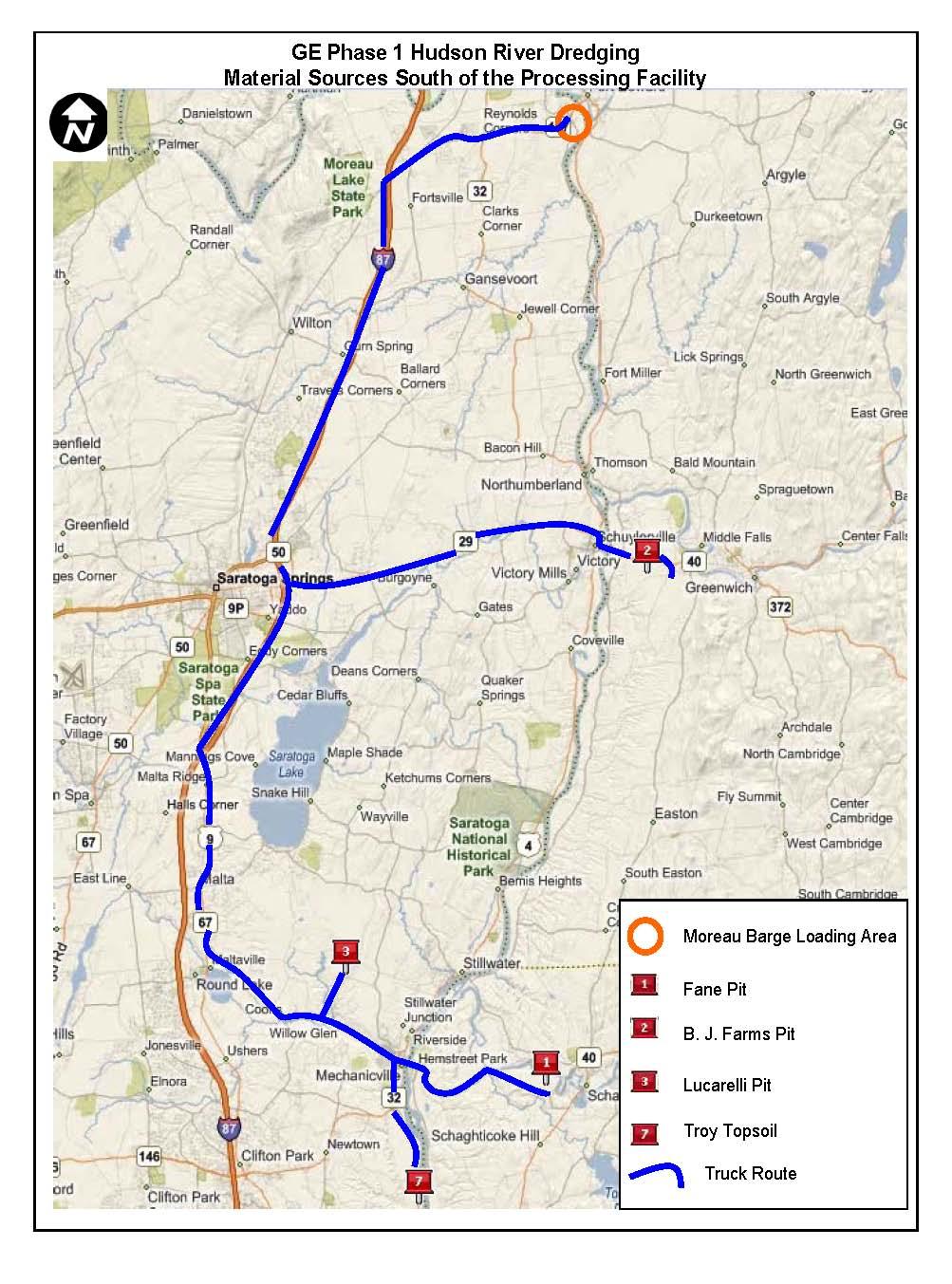
75